


 Loading...
Blackmagic Design Mini Converter SDI to HDMI 6G, Mini Converter HDMI to SDI, Mini Converter HDMI to SDI 4K, Mini Converter HDMI to SDI 6G, Mini Converter SDI to Analog Installation and Operation Manual
...
Installation and Operation Manual
Blackmagic
Converters
September 2020
English, , Français, Deutsch, Español, ,, Русский, Italiano, Português and Türkçe.

Languages
To go directly to your preferred language, simply click on the hyperlinks listed in the contents below.
English |
3 |
|
100 |
Français |
198 |
Deutsch |
296 |
Español |
394 |
|
492 |
|
590 |
Русский |
688 |
Italiano |
786 |
Português |
884 |
Türkçe |
982 |

Welcome
Thank you for purchasing Blackmagic Converters for your production needs.
Blackmagic Mini Converters and Micro Converters give you a solution for virtually any conversion you could need. Mini Converters convert analog to digital, digital to analog, SDI to audio, audio to SDI, up, down and cross conversion, SDI distribution, and can even provide a sync generator for locking all your video equipment to the same reference signal. Blackmagic Micro Converters are small and designed for popular conversions such as SDI to HDMI and HDMI to SDI so you can plug any
HDMI output into SDI video recorders and switchers, or plug SDI video equipment into HDMI monitors.
This instruction manual contains all the information you need to start using your Blackmagic Converters.
Please check the support page on our web site at www.blackmagicdesign.com for the latest version of this manual and for updates if your Blackmagic Converter has internal software. Keeping your internal software up to date will always ensure you get all the latest features. When downloading software, please register with your information so we can keep you updated when new software is released. We are constantly working on new features and improvements, so we would love to hear from you!
Grant Petty
CEO Blackmagic Design
Contents
Blackmagic Converters
Getting Started |
5 |
Plugging in Power |
5 |
Plugging in Video |
5 |
Plugging in Audio |
7 |
Installing Administration Software |
8 |
Installing Blackmagic Converters Setup |
8 |
Updating the Internal Software |
9 |
Updating Mini Converter SDI |
|
Distribution 4K |
10 |
Changing Settings |
11 |
Changing Settings using Switches |
11 |
Changing Settings using |
|
Blackmagic Converters Setup |
12 |
About Tab |
13 |
Setup Tab |
13 |
Blackmagic Converter Models |
14 |
Teranex Mini Converters |
14 |
Blackmagic Micro Converters |
15 |
Micro Converter SDI to HDMI 3G |
15 |
Micro Converter HDMI to SDI 3G |
17 |
Micro Converter BiDirectional |
|
SDI/HDMI 3G |
19 |
Camera Control and Tally between |
|
SDI and HDMI |
21 |
Micro Converter SDI to HDMI |
22 |
Micro Converter HDMI to SDI |
24 |
Micro Converter BiDirectional SDI/HDMI |
26 |
Blackmagic Mini Converters |
28 |
Mini Converter SDI to HDMI |
28 |
Mini Converter SDI to HDMI 4K |
31 |
Mini Converter SDI to HDMI 6G |
35 |
Mini Converter HDMI to SDI |
40 |
Mini Converter HDMI to SDI 4K |
43 |
Mini Converter HDMI to SDI 6G |
46 |
Mini Converter SDI to Analog |
49 |
Mini Converter SDI to Analog 4K |
54 |
Mini Converter Analog to SDI |
58 |
Mini Converter SDI to Audio |
62 |
Mini Converter SDI to Audio 4K |
65 |
Mini Converter Audio to SDI |
68 |
Mini Converter Audio to SDI 4K |
72 |
Mini Converter Optical Fiber |
76 |
Mini Converter Optical Fiber 4K |
77 |
Mini Converter Optical Fiber 12G |
78 |
Mini Converter Quad SDI to HDMI 4K |
79 |
Mini Converter SDI Distribution |
80 |
Mini Converter SDI Distribution 4K |
81 |
Mini Converter SDI Multiplex 4K |
82 |
Mini Converter Sync Generator |
85 |
Mini Converter UpDownCross |
87 |
Mini Converter UpDownCross HD |
91 |
Converter Setup Utility |
95 |
Help |
96 |
Regulatory Notices |
97 |
Safety Information |
98 |
Warranty |
99 |
4

Getting Started
Getting started with your Blackmagic Converter is as simple as plugging in power, plugging your source video into your converter’s video input, and plugging the video output into your destination equipment.
Plugging in Power
Plug in the included 12 volt power supply using the socket adapter for your country.
If your converter has a built in cable tie point, you can easily secure the power connection to your converter.
|
SDI |
LOCK |
SDI |
|
|
OUT |
|
|
|
|
ALT |
SDI |
|
|
IN |
|
|
|
SDI |
IN |
+12VPOWER
Locking the power cable to the converter’s cable tie point prevents accidental disconnection.
Micro Converter
Blackmagic Micro Converters are powered using USB-C or Micro USB connectors. This means you can easily connect power using the battery charger for some modern cell phones, or even power your converter via the USB port of your laptop computer. Any equipment capable of providing 5V via a standard USB to Micro USB cable or USB-C cable can power your Blackmagic Micro Converter.
Plugging in Video
To connect your video inputs and outputs, simply plug your source video into your converter’s video input and plug the video output into your destination equipment.
|
|
|
|
|
|
|
|
|
|
|
|
|
|
|
|
|
|
|
|
|
|
|
|
|
|
|
|
|
|
|
|
|
|
|
|
|
|
|
|
|
|
|
|
|
|
|
|
|
|
|
|
|
|
|
|
|
|
|
|
|
|
|
|
|
|
|
|
|
|
|
|
|
|
|
|
|
|
|
|
|
|
|
|
|
|
|
|
|
|
|
|
|
|
|
|
|
|
|
|
|
|
|
|
|
|
|
|
|
|
|
|
|
|
|
|
|
|
|
|
BNC |
|
HDMI |
Optical Fiber |
||||||||||||||||
Depending on your Blackmagic Converter model,
the video connectors may be BNC, HDMI, or optical fiber LC.
Getting Started |
5 |
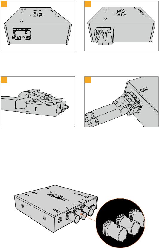
Optical Fiber Connectors
Some Blackmagic Converter models include an SFP socket to accept a compatible SFP optical fiber module that supports up to 3G, 6G or 12G-SDI video. The module is an optical transmitter and receiver with sockets for optical fiber cables.
1 |
2 |
Examine the Optical Out/In socket to make sure it is free of dust.
Remove the protective cover from the SFP optical fiber module, and insert it in the SFP socket.
A locking pin clicks into position to secure the module in the socket.
3 |
4 |
The optical fiber cables have latching tabs on top to make sure they don’t fall out.
Plug in the optical fiber cables. Confirm the Out and In plugs are in the correct sockets, and that the locking tabs on the plugs hold the lever of the SFP optical fiber module upright.
Fail Safe Alternate SDI inputs
Some Blackmagic Converter models include alternative SDI inputs for redundancy.
These inputs are labeled ‘Alt SDI In’ and will immediately take over should the primary SDI input signal fail. In this rare scenario, the SDI LOCK LED will flash, indicating that the converter has switched to the ALT SDI input.
R- ANALOG
L - AESA/EBNALOU G or
HDMI
SDI |
|
|
|
|
|
|
|
|
|
SDI |
LOCK |
|
|
|
SDI |
|
|
|
|
|
OUT |
|
|
|
|
|
|
|
|
|
ALT |
SDI |
|
|
|
|
|
IN |
|
|
|
|
|
|
|
|
|
SDI |
IN |
|
|
|
|
+12VPOWER |
|
|
|
|
|
|
|
|
|
|
|
DI |
|
SDI |
LOCK |
|
OUT |
||
|
ALT |
SDI |
|
|
IN |
|
|
|
SDI |
IN |
|
Converters with an ‘Alt SDI’ input will automatically switch to this secondary input should the primary SDI input signal fail.
Getting Started |
6 |
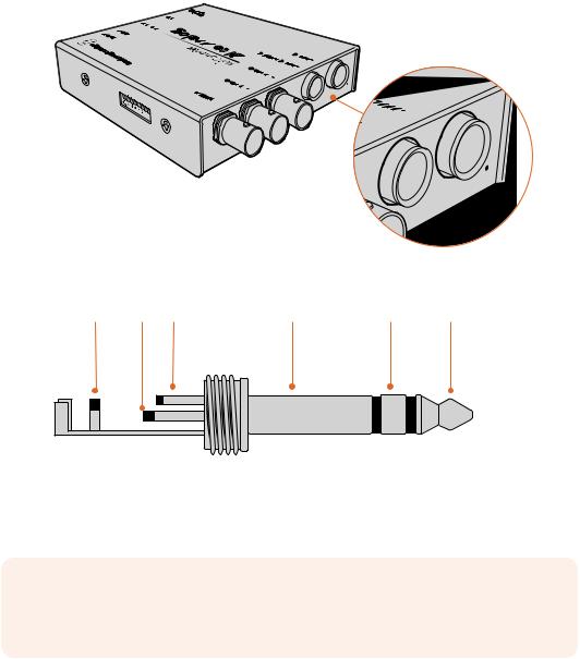
Plugging in Audio
Jack Audio Connectors
Some Blackmagic Converters have built in 1/4" jacks, so you can easily plug in balanced external analog or digital AES/EBU audio. The 1/4" jacks are balanced TRS connectors. TRS stands for Tip, Ring, Sleeve which refers to the three contacts of the jack connector.
|
|
|
V+12 |
|
|
NI |
RPOWE |
|
|
SDI |
|
|
|
NI |
|
|
|
DIS |
|
|
TOU |
TAL |
|
KLOC |
SDI |
|
|
|
|
||
SDI |
|
|
|
|
|
|
DIS |
UAES/EB |
GANALO |
R |
|
|
or |
|
- |
|
C |
GANALO |
|
|
|
|
L |
|
|
|
OVIDE |
- |
|
|
|
|
|
|
||
|
-S |
|
|
|
|
or |
|
|
|
|
Y |
|
|
|
Y |
-R |
|
|
|
OVIDE |
|
|
|
|
-S |
|
|
|
|
or |
|
|
|
|
Y |
|
|
|
|
-B |
|
|
|
|
LNTSC/PA |
|
|
|
|
or |
|
|
|
|
Y |
|
|
|
|
GANALO |
|
- |
|
NA |
R |
|
|
- |
|
L |
|
If your Blackmagic Converter has jack audio connectors, you can plug in balanced analog or AES/EBU audio.
Below is an illustration showing the wiring pins inside the male 1/4" jack connector if you want to make your own audio cables.
Sleeve (Ground) Tip (+) Ring (–) |
Sleeve (Ground) |
Ring (–) |
Tip (+) |
The audio jack illustration on the previous page shows the jack connector’s positive, negative and ground wiring pins. If you need to reverse the polarity of your analog audio cable to suit your audio equipment, you can simply swap the positive and negative wiring on the tip and ring pins.
NOTE If you are connecting stereo analog audio, it’s worth mentioning that if you reverse the polarity for one channel jack connector, make sure you do the same for the second or your stereo analog audio will be out of phase.
Getting Started |
7 |
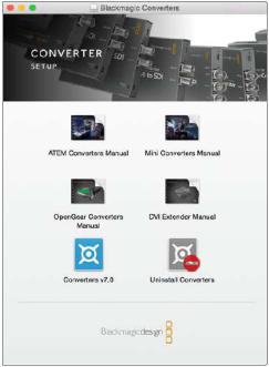
Installing Administration Software
Installing Blackmagic Converters Setup
Blackmagic Converters Setup is used to change settings on your converter and to update your converter’s internal software. The settings available will depend on the converter you are using. However, some Blackmagic Converters don’t require any adjustable settings and don’t have internal software, therefore these particular converters will not have a USB connector. If your converter is one of these, you can go straight to your converter model in this manual to learn more about it.
Blackmagic Converters Setup can be installed on Mac OS and Windows computers.
Installation on Mac
1Download the Blackmagic Converters Setup software from www.blackmagicdesign.com
2Unzip the downloaded file and open the resulting disk image to reveal its contents.
3Double click the installer and follow the prompts to complete the installation.
4When the installation has finished, click ‘close’. Blackmagic Converters Setup is now installed.
Installation on Windows
1Download Blackmagic Converters Setup from www.blackmagicdesign.com
2Unzip the downloaded file. You should see a Blackmagic Converters Setup folder containing this PDF manual and the Blackmagic Converters Setup installer.
3Double click the installer and follow the prompts to complete the installation.
4Click ‘finish’ to complete the installation.
Blackmagic Converters Setup is now ready to use.
Installing Administration Software |
8 |
Updating the Internal Software
If your Blackmagic Converter has a USB connector, then you may have additional settings you can change, plus you can update your converter with the latest internal software. The latest software can be downloaded from the Blackmagic Design support center at www.blackmagicdesign.com/support.
When updating Blackmagic Micro Converters, power is already supplied via the USB port, so you don’t have to worry about connecting power.
On Blackmagic Mini Converters, you will need to ensure your converter is powered before connecting to your computer via USB.
1Power your converter.
2Attach a USB cable from the computer to the converter and launch the Blackmagic Converter Setup.
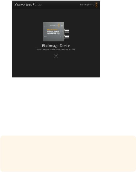
Your Blackmagic Converter will be displayed on the setup utility’s home page. If you have more than one converter connected via USB, click on the arrow icons on the left or right side of the home page to select your desired converter.
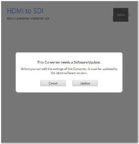
If Blackmagic Converters Setup detects an earlier version of your converter’s internal software, it will prompt you to update.
If no converter is connected, the home page will display “no converters found”. If you have a converter connected to your computer via USB, but you don’t have power plugged in, the home page may display ‘no power connected’. Simply plug power into your converter to access
the settings.
If Blackmagic Converters Setup contains newer internal software than that currently installed in your Blackmagic Converter, it will prompt you to update. Simply follow the on screen instructions to complete the update.
Installing Administration Software |
9 |
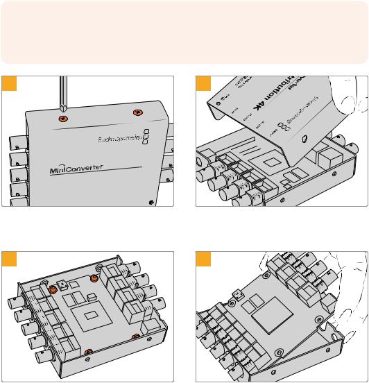
Updating Mini Converter SDI Distribution 4K
Blackmagic Mini Converter SDI Distribution 4K has an internal USB connector. This mini converter has no user adjustable settings, so you will never need to connect setup software. Very occasionally, though, internal software updates will be released to improve compatibility. For example, Blackmagic Converters Software version 7.0.9 improves this mini converter’s compatibility with level A 3G SDI signals.
If a particular update applies to the equipment you are using with Mini Converter
SDI Distribution 4K, follow these steps to access your mini converter’s USB connector:
NOTE Make sure you disconnect power before accessing your Mini Converter SDI Distribution 4K. We recommend this job is undertaken by a qualified engineer using an anti static strap.
1 |
2 |
SDI OUT |
|
|
|
SDI OUT |
|
|
|
|
SDI |
Distribution |
4K |
SDI OUT |
|
||
|
|
|
SDI OUT
SDI OUT
SDI OUT
SDI IN
SDI OUT
, HD and Ultra |
HD |
|
POWER +12V
Using a philips head screwdriver, remove the four (M3) screws on the sides of Mini Converter SDI Distribution 4K.
Slide off the external cover.
3 |
4 |
Using a T10 torx screwdriver, remove the four screws connecting the circuit board to Mini Converter SDI Distribution 4K’s frame.
Gently pull the circuit board from the frame to access the USB connector.
Installing Administration Software |
10 |
5 |
6 |
SDI OUT
SDI OUT
SDI OUT
SDI OUT
SDI OUT
SDI Distribution |
4K |
|
SDI OUT
SDI IN
SDI OUT
g SD, HD and |
Ultra |
HD |
|
|
POWER +12V
Plug in your Mini Converter SDI Distribution 4K’s power supply and connect it to a computer using a USB cable. Update the internal software as you would any other mini converter.
Repeat steps 1 - 4 in reverse to reassemble Mini Converter SDI Distribution 4K.
NOTE When handling your Mini Converter SDI Distribution 4K’s circuit board, be careful to always hold it by the edges to prevent accidentally short circuiting internal components.
Changing Settings
If your Blackmagic Converter has adjustable settings, there are two ways you can change them. You can use the built in switches on the side of your converter, or you can change settings using the Blackmagic Converters Setup utility software. The utility is also used to change any settings that can’t be set using the switches, for example analog video and audio levels.
Changing Settings using Switches
Many Blackmagic Converter models have built in switches.
To change a switch setting simply push the switch up or down using the tip of a pen. This turns the switches on or off. With 8 switches, this gives you many combinations so you can choose exactly the conversion settings you want.
You’ll find a switch settings diagram printed on the base of your converter. Ensure your switch settings correspond to the legend by observing the switch numbers from 1 to 8, left to right.
Change settings by adjusting the switches with a pen.
Changing Settings |
11 |
For a full description of the switches and their settings, refer to your converter model in this manual. Even though switch settings are printed on the base of your converter, new features in later updates can add new settings so it’s worth checking the latest version of this manual for the most up to date information. You can download the latest version from the
Blackmagic Design support center at www.blackmagicdesign.com/support.
Changing Settings using Blackmagic Converters Setup
Once Blackmagic Converters Setup is installed on your computer, connect the setup utility to your Blackmagic Converter via USB.
The Blackmagic Converters setup utility lets you update your converter’s internal software and adjust settings using a Mac OS or Windows computer.
The first thing you’ll see when launching the software is the ‘home’ page. If you have more than one converter connected to your computer, select your desired converter by clicking the arrows on the left and right side of the Blackmagic Converters Setup home page.
To change settings, click on the ‘settings’ icon below the image of your Blackmagic Converter. Adjustments will be immediately saved to your converter. This means if power is lost, your settings will be reestablished as soon as power is restored.
Even though most settings are configured using the built in switches, some settings can only be set using the setup software, for example adjusting analog video or audio levels.
TIP Teranex Mini Converters are 12G-SDI converters that support even more video formats including up to 4K DCI 60p. If you are looking for information on how to use a Teranex Mini Converter, including how to change settings using the
Blackmagic Teranex Setup utility, refer to the Teranex Mini Converters manual.
You can download the most up to date manual from the Blackmagic Design support center at www.blackmagicdesign.com/support
Changing Settings |
12 |

About Tab
The ‘about’ tab in Blackmagic Converters Setup is common across many converter models. You can use the settings in this tab to name your Blackmagic Converter. Simply click in the ‘name’ text box and type your desired converter name. Click ‘save’ to confirm the change.
The 'about' tab in Blackmagic Converters Setup displays information about the current software version.
The ‘Software Information’ menu in the ‘about’ tab identifies which software version your Blackmagic Converter is running. If your converter’s internal software is older than the current version that comes with Blackmagic Converters Setup, an update button will be present here that allows you to bring your converter’s software up to date.
Setup Tab
Some Blackmagic Converters use a ‘setup’ tab to name your converter and check software information. The setup tab will also contain other settings specific to your converter. For more information about the setup settings for your converter, refer to the unit’s dedicated section in this manual.
Changing Settings |
13 |
Blackmagic Converter Models
Blackmagic Converters provide conversion solutions for all types of conditions. For example, Mini Converters are tough and lightweight so you can mount them on video equipment or video trays. Blackmagic Micro Converters are tiny SDI to HDMI and HDMI to SDI converters that can be powered via USB so are perfect for attaching to monitors and laptop computers.
The following pages contain information about your Blackmagic Converter, plus switch settings and setup software settings.
Teranex Mini Converters
Blackmagic Teranex Mini Converters are 12G-SDI converters that support video formats up to 4K DCI 60p. These converters can be controlled using an optional Teranex Mini Smart Panel with built in LCD, buttons and a rotary knob, and can be powered via Ethernet. If you are looking for information about these converters, including controlling them via the Blackmagic Teranex Setup utility, refer to the Teranex Mini Converters manual which you can download from the Blackmagic Design support center at www.blackmagicdesign.com/support
Teranex Mini Converters |
14 |
Blackmagic Micro Converters
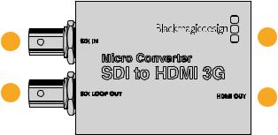
Micro Converter SDI to HDMI 3G
With Micro Converter SDI to HDMI 3G you can connect a huge range of HDMI displays and video projectors to SDI based equipment. Your Micro Converter SDI to HDMI 3G automatically detects between SD/HD/3G-SDI and converts to HDMI with embedded audio. This model can also display a 3D LUT on both the HDMI and SDI loop output.
This tiny broadcast quality converter is protected by a strong aluminum chassis and powers over USB-C, meaning you can power your Blackmagic Micro Converter via your laptop or television’s USB connector using a USB-C cable. USB-C cables are used to connect some cell phones to chargers and laptops, so if you have one of these, you can use the same cable. If the USB connector on your cable is a different type, the correct cable can be purchased from most electronic equipment stores.
1 |
SDI IN |
3 |
|
|
Micro Converter |
|
|
SDI to HDMI 3G |
|
2 |
SDI LOOP OUT |
HDMI OUT 4 |
|
|
|
Connectors
1SDI IN
Primary SDI input BNC connector. The small 'lock' LED next to the BNC connector will illuminate when an SDI input is detected and the HDMI output is connected. When flashing, the LED indicates an SDI input is present, but no HDMI output has been detected. If the LED lock light is off no SDI input or HDMI output is present.
2SDI LOOP
Loop through output of your SDI input BNC connector.
3USB-C / POWER
Connect 5V power using a standard USB to USB-C cable. Also connects to Blackmagic Converters Setup software via your Mac OS or Windows Computer. A small white LED light next to the USB-C port will illuminate when connected to a power source.
4HDMI OUT
HDMI type A video output.
Blackmagic Converters Setup Settings
The Blackmagic Converters Setup utility can be used to change settings and update your Micro Converter’s software. You can access these settings by moving between the ‘setup’ and
‘LUTs’ tabs.
The ‘setup’ tab features the unit name and software version along with HDMI output levels and audio mapping options for 5.1 surround.
Blackmagic Micro Converters |
15 |
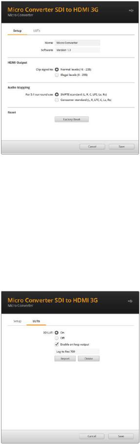
HDMI Output
To stay within HDMI legal broadcast levels, select ‘normal levels’. To allow video levels to conform to the SDI input, select ‘illegal levels’. We recommend using normal levels.
Audio Mapping
For 5.1 surround, select your desired audio mapping from either SMPTE or consumer standard.
Reset
You can also reset your converter to factory settings by clicking the ‘factory reset’ option.
LUTs
To add a 3D LUT on the HDMI output, select ‘on’ and click on the ‘import’ button. Now navigate to the location of the LUT you want to import and select it. Click ‘save’.
To add the LUT on the SDI loop out, select the ‘enable on loop output’ checkbox. Disable the LUT by selecting the ‘off’ option. To remove the loaded LUT, simply click the ‘delete’ button.
Blackmagic Micro Converters |
16 |
Micro Converter SDI to HDMI 3G Block Diagram
|
|
|
|
|
Automatic |
|
|
|
|
|
Input automatically |
|
SD/HD/3G-SDI Cable |
|
|
|
|
|
|
detects between |
|
Driver and Re-clocker |
|
|
Loop SDI |
|
|
|
SD/HD/3G-SDI |
|
|
|
|
||
|
|
|
|
|
|
Out |
||
|
|
|
|
|
|
|
|
|
|
|
Equalizer and |
|
Customizable |
HDMI Video and |
|
|
|
|
|
|
|
|
|
|||
|
|
10-bit De-serializer |
Video Processor |
Audio Formatter |
|
|
HDMI Out |
|
|
|
|
|
|||||
SDI In |
|
|
|
|
||||
Central Processor
and Firmware
USB-C
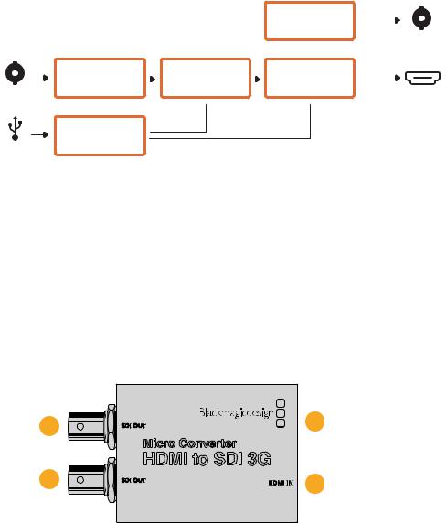
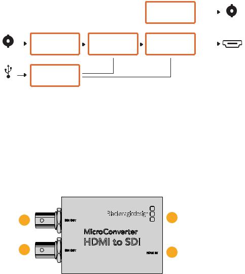
Micro Converter HDMI to SDI 3G
You can use Micro Converter HDMI to SDI 3G to convert the HDMI ouput from video equipment such as HDV cameras and game consoles to SDI. This means you can send video signals from HDMI over SDI using the longest SDI cables. You can even add SDI outputs to computers with HDMI compatibility.
This tiny broadcast quality converter is protected by a strong aluminum chassis and powers over USB-C, meaning you can power your Blackmagic Micro Converter via your laptop or television’s USB connector using a common USB-C cable. USB-C cables are used to connect some cell phones to chargers and laptops, so if you have one of these, you can use the same cable. If the USB connector on your cable is a different type, the correct cable can be purchased from most electronic equipment stores.
1 |
SDI OUT |
3 |
|
|
Micro Converter |
|
|
HDMI to SDI 3G |
|
2 |
SDI OUT |
HDMI IN 4 |
|
|
|
Connectors
1SDI OUT
SDI video output BNC connector.
2SDI OUT
Second SDI output.
3USB-C / POWER
Connect 5V power using a standard USB to USB-C cable. Also connects to Blackmagic Converters Setup software via your Mac OS or Windows Computer. A small white LED light next to the USB-C port will illuminate when connected to a
power source.
4HDMI IN
HDMI Type A video input. The small 'lock' LED next to the HDMI IN connector will illuminate when a valid HDMI input is detected.
Blackmagic Micro Converters |
17 |
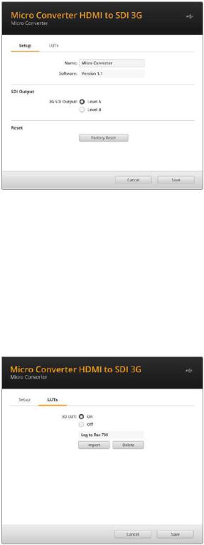
Blackmagic Converters Setup Settings
The Blackmagic Converters Setup utility can be used to change settings and update your Micro Converter’s software. You can access these settings by moving between the ‘setup,’ and ‘about’ tabs.
The ‘setup’ tab contains the software information and name for your converter.
SDI Output
The 3G SDI Output lets you select between Level A or Level B 3G-SDI. This setting lets you change the 3G-SDI output standard to maintain compatibility with equipment that can only receive level A or level B 3G-SDI video. Level B is the default setting.
Reset
You can also reset your converter to factory settings by clicking the ‘factory reset’ option.
LUTs
To add a 3D LUT on the SDI output, select ‘on’ and click on the ‘import’ button. Now navigate to the location of the LUT you want to import and select it. Click ‘save’.
To remove the loaded LUT, simply click the ‘delete’ button.
Blackmagic Micro Converters |
18 |

Micro Converter HDMI to SDI 3G Block Diagram
Input automatically detects between SD/HD/3G-SDI
|
|
HDMI Video |
Customizable |
Automatic |
|
SDI Out |
|
|
|
||||
|
|
SD/HD/3G-SDI Cable |
|
|
||
|
|
and audio decoder |
Video Processor |
|
|
|
|
|
|
|
|||
|
|
Driver and Re-clocker |
|
SDI Out |
||
HDMI In |
|
|
||||
|
|
|
||||
|
|
|
|
|||
Central Processor
and Firmware
USB-C
Micro Converter BiDirectional SDI/HDMI 3G
Micro Converter BiDirectional SDI/HDMI 3G lets you convert HDMI to SDI and back again while maintaining tally and camera control in both signal formats. This means you can now connect a Blackmagic Pocket Cinema Camera 4K or 6K to any SDI ATEM switcher, or an URSA Broadcast camera to an ATEM Mini, all while maintaining camera control and tally. You can also use this micro converter as an SDI extender so you can connect HDMI Blackmagic Design cameras to ATEM Mini switchers over far greater cable lengths.
If you have only one input connected, the SDI and HDMI outputs both become loop outputs so you can feed the input signal to other HDMI and SDI equipment, for example a SmartView monitor.
Your Micro Converter BiDirectional SDI/HDMI 3G automatically detects the SD/HD/3G-SDI input format and sets the output format to match.
This tiny broadcast quality converter is powered over USB, meaning you can power the unit from your laptop or television’s USB connector using a common USB-C cable. USB-C cables are used to connect some cell phones to chargers and laptops, so if you have one of these, you can use the same cable. If the USB connector on your cable is a different type, the correct cable can be purchased from most electronic equipment stores.
3
1 HDMI
 OUT
OUT
|
|
MicroConverter SDI OUT |
4 |
|
|
BiDirectional SDI/HDMI 3G |
|
2 |
HDMI IN |
SDI IN |
5 |
|
|
Connectors
1HDMI OUT
HDMI type A video output.
2HDMI IN
HDMI Type A video input. The small 'lock' LED next to the HDMI IN connector will illuminate when a valid HDMI input is detected.
Blackmagic Micro Converters |
19 |
3USB-C / POWER
Connect 5V power using a standard USB to USB-C cable. Also connects to Blackmagic Converters Setup software via your Mac OS or Windows Computer. A small white LED light next to the USB-C port will light up when connected to a power source.
4SDI OUT
SDI video output BNC connector.
5SDI IN
SDI video input BNC connector. The small 'lock' LED next to the SDI IN will illuminate when a valid SDI input is detected.
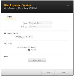
Blackmagic Converters Setup Settings
The Blackmagic Converters Setup utility can be used to change settings and update your Micro Converter’s software.
The ‘setup’ tab contains the unit name and software version along with SDI Camera Control and SDI Output options.
The Setup options for Micro Converter BiDirectional SDI/HDMI 3G.
SDI Camera Control
To ensure CCU and tally data from the ATEM switcher is sent to the correct camera the 'ATEM Camera ID' number should be set to match the ATEM's input number.
SDI Output
The ‘3G Output’ setting lets you select between Level A or Level B 3G-SDI. This changes the 3G-SDI output standard to maintain compatibility with equipment that can receive only level A or level B 3G-SDI video. The default setting is Level B.
Reset
You can also reset your converter to factory settings by clicking the ‘factory reset’ option.
Blackmagic Micro Converters |
20 |
Camera Control and Tally between SDI and HDMI
Using Blackmagic Pocket Cinema Camera with ATEM Constellation 8K
In this scenario, the micro converter is used to connect the camera’s HDMI output to the ATEM’s SDI input. The bidirectional converter allows the camera control and tally data to be fed back through the converter and into the camera via the Consumer Electronics Control CEC data in the HDMI signal.
The Micro Converter’s HDMI output can be used for remote monitoring.
ATEM Constellation 8K
PROD |
ENG |
|
|
|
|
|
|
|
|
|
|
|
|
TALK |
TALK |
1 |
2 |
3 |
4 |
5 |
6 |
7 |
8 |
9 |
10 |
|
|
|
|
|
|
||||||||||
CALL |
PGM |
|
|
|
|
|
|
|
|
|
|
|
|
MIX |
11 |
12 |
13 |
14 |
15 |
16 |
17 |
18 |
19 |
20 |
|
|
|
|
|
|
|
||||||||||
|
|
21 |
22 |
23 |
24 |
25 |
26 |
27 |
28 |
29 |
30 |
|
|
|
|
31 |
32 |
33 |
34 |
35 |
36 |
37 |
38 |
39 |
40 |
CUT |
AUTO |
SDI |
SDI |
CCU and |
Program |
||
|
Return |
Tally Data |
|
Feed |
|
|
HDMI OUT |
|
CEC Data |
|
MicroConverter SDI OUT |
|
BiDirectional SDI/HDMI 3G |
|
|
HDMI IN |
SDI IN |
HDMI |
|
|
|
|
|
Blackmagic Pocket |
Micro Converter |
|
Cinema Camera 6K |
BiDirectional SDI to HDMI 3G |
|
Blackmagic URSA with ATEM Mini
Here the converter is used to connect the camera’s SDI output to an ATEM Mini’s HDMI input. The SDI signal from the camera is converted to HDMI and sent to the ATEM Mini. CEC data is returned to the Micro Converter and converted to CCU and tally data, then sent back to the camera over SDI.
ATEM Mini
CCU and Tally Data
HDMI CEC Data |
SDI |
SDI |
Blackmagic URSA Mini
HDMI OUT
MicroConverter SDI OUT
BiDirectional
 SDI/H
SDI/H
 DMI 3G
HDMI IN
SDI IN
Micro Converter
BiDirectional SDI to HDMI 3G
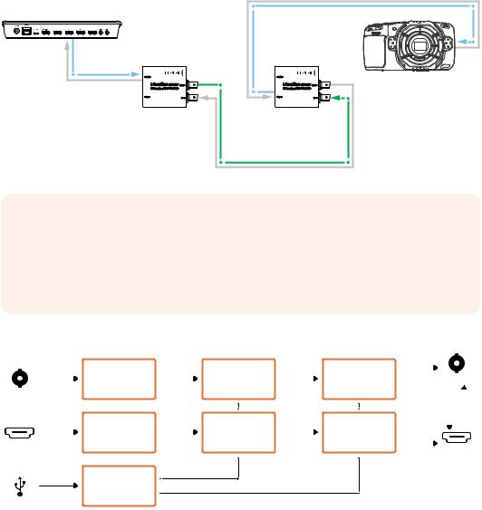
Using 2 Micro Converters as an SDI Extender
As SDI allows connections over longer distances than HDMI you can connect 2 BiDirectional Micro Converters together using an SDI cable and extend the range of HDMI equipment while maintaining camera control and tally data.
For example, an ATEM Mini can be connected to a Blackmagic Pocket Cinema Camera 6K. As shown in the example below, CEC data from the ATEM Mini is sent to the first Micro Converter over HDMI and then sent between the converters as CCU and tally data over SDI. The second converter then sends CEC data back to the camera over HDMI.
Blackmagic Micro Converters |
21 |
ATEM Mini
HDMI |
CEC Data |
|
MicroConverter |
|
BiDirectional SDI/HDMI 3G |
Micro Converter
BiDirectional
SDI to HDMI 3G
HDMI |
CEC Data |
|
|
|
Blackmagic Pocket |
|
MicroConverter |
Cinema Camera 6K |
|
BiDirectional SDI/HDMI 3G |
|
|
Micro Converter |
|
|
BiDirectional |
|
|
SDI to HDMI 3G |
|
CCU and Tally Data |
|
|
|
SDI |
|
NOTE The micro converter’s HDMI output will automatically detect if video is present on the SDI input. If no video is detected the HDMI output will become a loop out of the HDMI input and can be used for remote monitoring.
Additionally, any video and audio connected to the converter’s HDMI input will be transmitted on the SDI output.
Micro Converter BiDirectional SDI/HDMI 3G Block Diagram
|
|
Equalizer and |
|
Customizable |
|
Cable Driver |
|
SDI Out |
||
|
|
10-bit De-serializer |
|
Video Processor |
|
Re-Clocker |
|
|||
|
|
|
|
|||||||
|
|
|
|
|
|
|
|
|||
SDI In |
|
|
|
|
|
|
|
|
||
|
|
HDMI Video and |
|
Customizable |
|
HDMI Video and |
|
|
|
|
|
|
|
|
|
|
|
|
|||
|
|
|
|
|
|
|
|
|||
|
|
Audio Decoder |
|
Video Processor |
|
Audio Formatter |
|
|
|
|
|
|
|
|
|
|
|
|
|||
HDMI In |
|
|
|
|
|
HDMI Out |
||||
|
|
|
|
|
||||||
|
|
|
|
|
|
|
|
|||
Central
Processor and
Firmware
USB-C
Micro Converter SDI to HDMI
With Micro Converter SDI to HDMI you can connect a huge range of HDMI displays and video projectors to SDI based equipment. Your Micro Converter SDI to HDMI automatically detects between SD/HD/3G-SDI and converts to HDMI with embedded audio. This tiny broadcast quality converter is protected by a strong aluminum chassis and powers over USB, meaning you can power your Blackmagic Micro Converter via your laptop or television’s USB connector using a common micro USB cable. Micro USB cables are used to connect some cell phones to chargers and laptops, so if you have one of these, you can use the same cable. If the USB connector on your cable is a different type, the correct cable can be purchased from most electronic equipment stores.
Blackmagic Micro Converters |
22 |

1 |
SDI IN |
3 |
|
|
MicroConverter |
|
|
2 |
SDI to HDMI |
|
|
SDI LOOP OUT |
HDMI OUT |
4 |
|
|
|
Connectors
1SDI IN
Primary SDI input BNC connector.
2SDI LOOP
Loop through output of your SDI input BNC connector.
3Micro USB / POWER
Provides power from the included adapter or any equipment capable of providing 5V via a standard USB to Micro USB cable, such as a laptop or television. Also connects to Blackmagic Converters Setup software via your Mac OS or Windows Computer.
4HDMI OUT
HDMI type A video output.
Blackmagic Converters Setup Settings
The Blackmagic Converters Setup utility can be used to change settings and update your Micro Converter’s software. You can access these settings by moving between the ‘video’ and ‘about’ tabs.
The ‘about’ tab is detailed in the ‘changing settings’ section in this manual.
The ‘video’ tab for Micro Converter SDI to HDMI contains the following settings.
The ‘clip video output to legal levels’ setting is checked by default. This setting ensures your HDMI output is a true representation of the SDI input.
Blackmagic Micro Converters |
23 |
Processing menu
The ‘clip video output to legal levels’ checkbox controls clipping of your SDI input to ensure that it stays within HDMI legal levels and should be kept on by default.
Micro Converter SDI to HDMI Block Diagram
|
|
|
|
|
Automatic |
|
|
|
|
|
Input automatically |
|
SD/HD/3G-SDI Cable |
|
|
|
|
|
|
detects between |
|
Driver and Re-clocker |
|
|
Loop SDI |
|
|
|
SD/HD/3G-SDI |
|
|
|
|
||
|
|
|
|
|
|
Out |
||
|
|
|
|
|
|
|
|
|
|
|
Equalizer and |
|
Customizable |
HDMI Video and |
|
|
|
|
|
|
|
|
|
|||
|
|
10-bit De-serializer |
Video Processor |
Audio Formatter |
|
|
HDMI Out |
|
|
|
|
|
|||||
SDI In |
|
|
|
|
||||
Central Processor
and Firmware
Micro USB
Micro Converter HDMI to SDI
You can use Micro Converter HDMI to SDI to convert the HDMI ouput from video equipment such as HDV cameras and game consoles to SDI. This means you can send video signals from HDMI over SDI using the longest SDI cables. You can even add SDI outputs to computers with HDMI compatibility. This tiny broadcast quality converter is protected by a strong aluminum chassis and powers over USB, meaning you can power your Blackmagic Micro Converter via your laptop or television’s USB connector using a common micro USB cable. Micro USB cables are used to connect some cell phones to chargers and laptops, so if you have one of these, you can use the same cable. If the USB connector on your cable is a different type, the correct cable can be purchased from most electronic equipment stores.
1 |
SDI OUT |
|
|
|
|
MicroConverter |
|
2 |
SDI OUT |
HDMI to SDI |
|
HDMI IN |
|||
|
|
3
4
Connectors
1SDI OUT
SDI video output BNC connector.
2SDI OUT
Second SDI output.
3Micro USB / POWER
Provides power from the included adapter or any equipment capable of providing 5V via a standard USB to Micro USB cable, such as a laptop or television. Also connects to Blackmagic Converters Setup software via your Mac OS or Windows Computer to update the Micro Converter’s internal software.
4HDMI IN
HDMI type A video input.
Blackmagic Micro Converters |
24 |
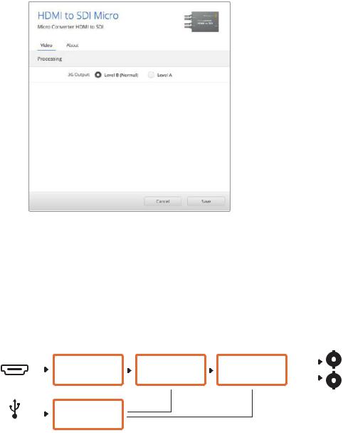
Blackmagic Converters Setup Settings
The Blackmagic Converters Setup utility can be used to change settings and update your Micro Converter’s software. You can access these settings by moving between the ‘video’, and ‘about’ tabs.
The ‘about’ tab is detailed in the ‘changing settings’ section in this manual.
The ‘video’ tab for Micro Converter HDMI to SDI contains the following settings.
Use the ‘video’ tab in Blackmagic Converters Setup to toggle SDI levels.
Processing menu
The ‘3G Output’ menu lets you select between Level A or Level B 3G-SDI. This setting lets you change the 3G-SDI output standard to maintain compatibility with equipment that can only receive level A or level B 3G-SDI video. Level B is the default setting.
Micro Converter HDMI to SDI Block Diagram
Input automatically detects between SD/HD/3G-SDI
|
|
HDMI Video |
Customizable |
Automatic |
|
SDI Out |
|
|
|
||||
|
|
SD/HD/3G-SDI Cable |
|
|
||
|
|
and audio decoder |
Video Processor |
|
|
|
|
|
Driver and Re-clocker |
|
SDI Out |
||
HDMI In |
|
|
||||
|
|
|
||||
|
|
|
|
|||
|
|
Central Processor |
|
|
|
|
|
|
and Firmware |
|
|
|
|
Micro USB |
|
|
|
|
||
Blackmagic Micro Converters |
25 |
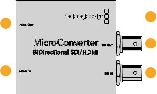
Micro Converter BiDirectional SDI/HDMI
Micro Converter BiDirectional SDI/HDMI converts SD and HD video from HDMI to SDI, and SDI to HDMI with embedded audio simultaneously. For example, you can convert the HDMI output from an HDV camera to SDI for longer cable lengths, while also converting an SDI return feed to HDMI so you can connect to an HDMI TV.
If you have only one input connected, the SDI and HDMI outputs both become loop outputs so you can feed the input signal to other HDMI and SDI equipment.
Your Micro Converter BiDirectional SDI/HDMI automatically detects SD/HD/3G-SDI input format and sets the output format to match.
This tiny broadcast quality converter is protected by a strong aluminum chassis. It is powered over USB, meaning you can power your Blackmagic Micro Converter BiDirectional SDI/HDMI from your laptop or television’s USB connector using a common micro USB cable. Micro USB cables are used to connect some cell phones to chargers and laptops, so if you have one of these, you can use the same cable. If the USB connector on your cable is a different type, the correct cable can be purchased from most electronic equipment stores.
3
1 HDMI
 OUT
OUT
|
|
MicroConverter SDI OUT |
4 |
|
|
BiDirectional SDI/HDMI |
|
2 |
HDMI IN |
SDI IN |
5 |
|
|
Connectors
1HDMI OUT
HDMI type A video output.
2HDMI IN
HDMI type A video input.
3Micro USB / POWER
Provides 5V power from any equipment capable of providing 5V via a standard USB to Micro USB cable, such as a laptop or television. Also connects to Blackmagic Converters Setup software via your Mac OS or Windows Computer.
4SDI OUT
SDI video output BNC connector.
5SDI IN
SDI video input BNC connector.
Blackmagic Micro Converters |
26 |
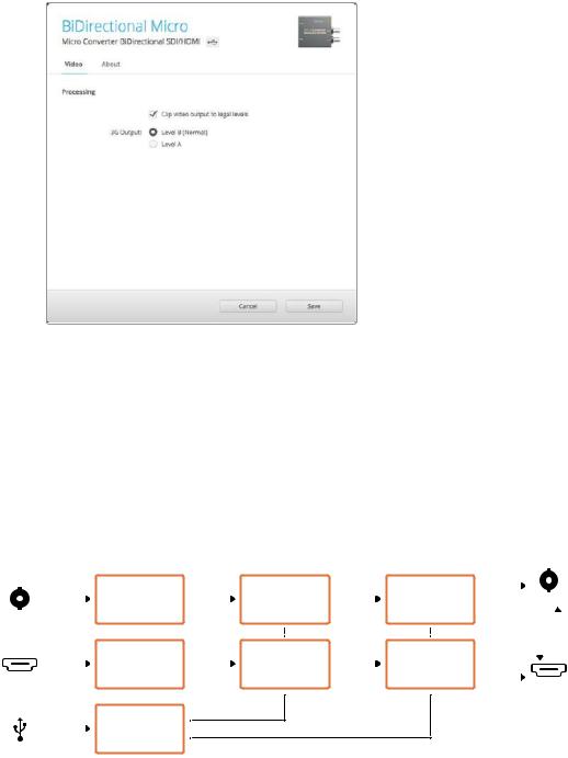
Blackmagic Converters Setup Settings
The Blackmagic Converters Setup utility can be used to change settings and update your Micro Converter’s software. You can access these settings by moving between the ‘video’, and ‘about’ tabs.
The ‘About’ tab is described in the ‘Changing Settings’ section in this manual.
The ‘Video’ tab for Micro Converter BiDirectional SDI/HDMI contains the following settings.
The ‘Clip video output to legal levels’ setting is checked by default. This setting makes sure your HDMI output is a true representation of the SDI input.
Processing menu
The ‘Clip video output to legal levels’ checkbox controls clipping of your SDI input to ensure that it stays within HDMI legal levels and should be kept on by default.
The ‘3G Output’ setting lets you select between Level A or Level B 3G-SDI. This changes the 3G-SDI output standard to maintain compatibility with equipment that can receive only level A or level B 3G-SDI video. The default setting is Level B.
Micro Converter BiDirectional SDI/HDMI Block Diagram
|
|
Equalizer and |
|
Customizable |
|
Cable Driver |
|
SDI Out |
||
|
|
10-bit De-serializer |
|
Video Processor |
|
Re-Clocker |
|
|||
|
|
|
|
|||||||
|
|
|
|
|
|
|
|
|||
SDI In |
|
|
|
|
|
|
|
|
||
|
|
HDMI Video and |
|
Customizable |
|
HDMI Video and |
|
|
|
|
|
|
|
|
|
|
|
|
|||
|
|
|
|
|
|
|
|
|||
|
|
Audio Decoder |
|
Video Processor |
|
Audio Formatter |
|
|
|
|
|
|
|
|
|
|
|
|
|||
HDMI In |
|
|
|
|
|
HDMI Out |
||||
|
|
|
|
|
||||||
|
|
|
|
|
|
|
|
|||
|
|
Central |
|
|
|
|
|
|
|
|
|
|
Processor and |
|
|
|
|
|
|
|
|
|
|
Firmware |
|
|
|
|
|
|
|
|
Micro USB |
|
|
|
|
|
|
|
|
||
Blackmagic Micro Converters |
27 |

Blackmagic Mini Converters
Mini Converter SDI to HDMI
Mini Converter SDI to HDMI can connect a huge range of HDMI displays and video projectors to SDI based equipment. Your Mini Converter SDI to HDMI automatically detects
between SD/HD/3G-SDI and converts to HDMI with embedded audio, plus balanced AES/EBU or analog audio out.
1
SDI to HDMI
2
3
SDI LOCK
SDI OUT
ALT SDI IN
SDI IN
POWER +12V
4
5
6
7
8
Connectors
1HDMI
HDMI type A video output.
2L - ANALOG or AES/EBU
Balanced left channel analog audio, or AES/EBU digital audio output on a 1/4" jack connector.
3R - ANALOG
Balanced right channel analog audio output 1/4" jack connector.
4Mini-B USB Port
Connects to the Converters Setup software via your Mac OS or Windows computer. The Mini Converter’s internal software is also updated using the USB port.
5SDI OUT
SDI video output on a BNC connector.
6ALT SDI IN
Redundant SDI input is provided as an optional back up.
7SDI IN
Primary SDI input.
8POWER +12V
12 volt power supply input.
Blackmagic Mini Converters |
28 |
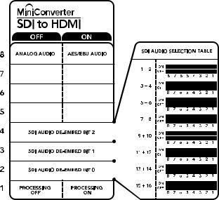
Switches
Switch 8 - Analog Audio, AES/EBU Audio
Set switch 8 to OFF to select balanced analog audio, or to ON for digital AES/EBU audio output.
Switch 4 - SDI Audio De-Embed Bit 2
Switches 4, 3 and 2 are grouped together to provide 8 ON/OFF combinations. Having eight different combinations allows eight independent pairs of audio channels to be de-embedded from your SDI input and output to HDMI, analog or AES/EBU audio.
Switch 3 - SDI Audio De-Embed Bit 1
See switch 4 description.
Switch 2 - SDI Audio De-Embed Bit 0
See switch 4 description.
Switch 1 - Processing Off - Processing On
This switch is not used.
The switch legend on the base of your converter gives you all the information you need to change conversion settings.
Mini Switch Settings Example
Experiment with the switches by setting your Blackmagic Mini Converter to de-embed SDI audio channels 1 and 2 and output to analog by setting switches 8, 4, 3 and 2 to the OFF position.
Blackmagic Mini Converters |
29 |
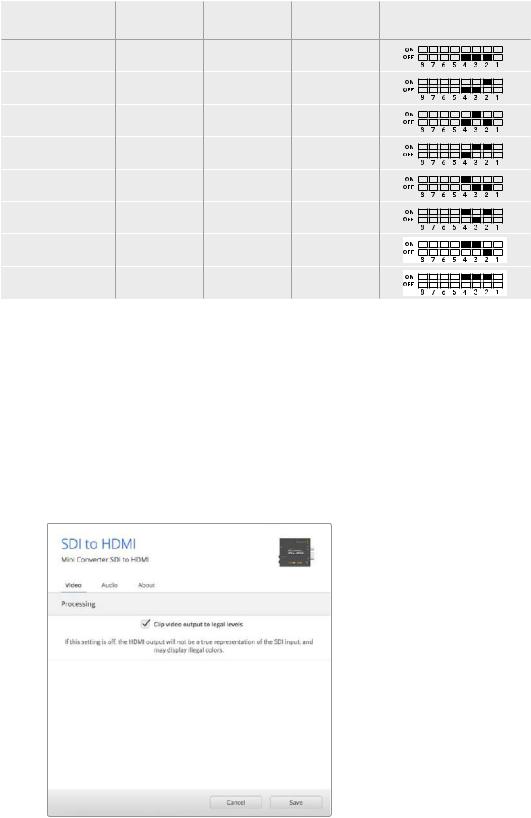
SDI Audio Selection Table
Audio Channels |
Switch 4 |
Switch 3 |
Switch 2 |
Switch Diagram |
1 and 2 |
OFF |
OFF |
OFF |
|
3 and 4 |
OFF |
OFF |
ON |
|
5 and 6 |
OFF |
ON |
OFF |
|
7 and 8 |
OFF |
ON |
ON |
|
9 and 10 |
ON |
OFF |
OFF |
|
11 and 12 |
ON |
OFF |
ON |
|
13 and 14 |
ON |
ON |
OFF |
|
15 and 16 |
ON |
ON |
ON |
|
Blackmagic Converters Setup Settings
The Converters Setup utility can be used to change settings and update your Mini Converter’s software. You can access these settings by moving between the ‘video’, ‘audio’, and ‘about’ tabs.
The ‘about’ tab is detailed in the ‘changing settings’ section in this manual.
The ‘video’ tab for Mini Converter SDI to HDMI contains the following settings.
Processing menu
The ‘clip video output to legal levels’ checkbox controls clipping of your SDI input to ensure that it stays within HDMI legal levels and should be kept on by default.
The ‘clip video to legal levels’ setting is checked by default.
This ensures that your HDMI video output stays within legal levels.
The ‘audio’ tab for Mini Converter SDI to HDMI contains the following settings.
Blackmagic Mini Converters |
30 |
Loading...