


Atem Mini
Table of contents
 Loading...
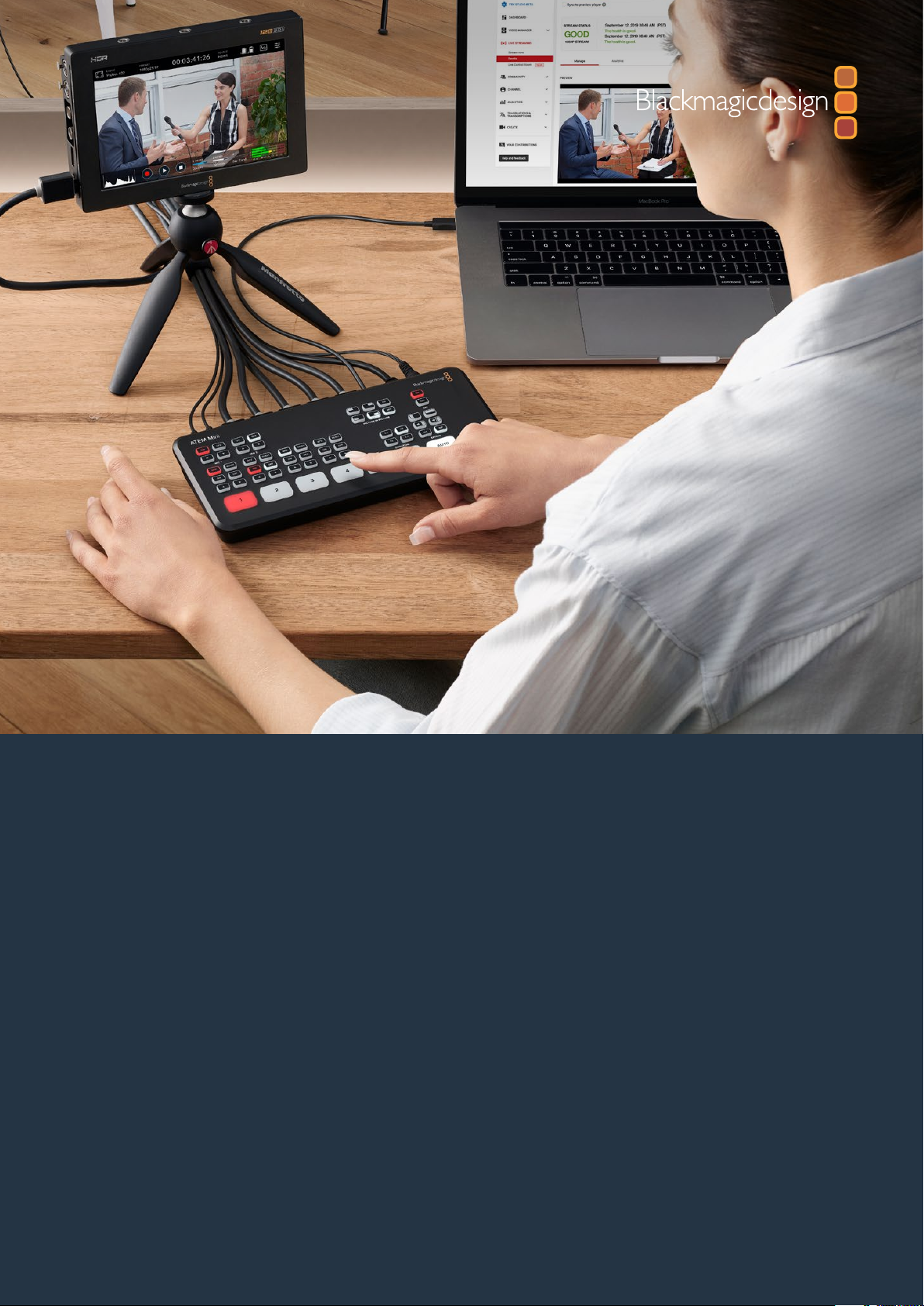
Installation and Operation Manual
ATEM Mini
November 2019

English
Welcome
Thank you for purchasing ATEM Mini for your live production streaming!
If you’re new to live production switchers, then you’re about to become involved in the most
exciting part of the broadcast industry and that’s live production! There is nothing like live
production and it’s so easy to become addicted to the adrenaline rush of editing in real time
while the live event unfolds before your eyes.
ATEM Mini is a small live production switcher that automatically converts 720p and 1080p HD
video and connects it directly to your computer via USB. The computer sees your ATEM Mini
as a webcam so it can be streamed online using your favorite online streaming application like
YouTube or OBS Studio.
ATEM Mini uses the same internal video processing used in the largest ATEM switchers, so even
though the unit is small and portable, you get the same amazing level of control and professional
features so it is very powerful. You can use the high quality buttons on the built in control panel,
or launch ATEM Software Control and perform more complex switching. For example, you can
manage all your graphics, set up keyers, record and run macros, and even mix and enhance your
audio using a full audio mixer with faders and advanced EQ and dynamics controls.
ATEM Mini lets you start small, then expand your ATEM workflow as your projects grow.
There really is no limit to what you can do! We hope you get years of use from ATEM Mini and
have lots of fun with your live production!
This instruction manual should contain all the information you’ll need for installing your
ATEM Mini and getting started.
Please check the support page on our web site at www.blackmagicdesign.com for the latest
version of the ATEM software. When downloading software, please register with your information
so we can keep you updated when new software is released. We are constantly working on new
features and improvements, so we would love to hear from you!
Grant Petty
CEO Blackmagic Design

Contents
ATEM Mini
Getting Started 5
Plugging in Power 5
Plugging in Video Sources 6
Plugging in a Monitor and Testing Inputs 6
Connect a Microphone 7
Connect your Computer 8
Setting the Webcam Source 8
Using Open Broadcaster 8
Switching your Production 8
Using Cuts and Transitions 9
Switching Sources using a Cut 9
Switching Sources using an
Auto Transition 9
Transition Styles and DVEs 10
Controlling Audio 10
Using Picture in Picture 12
Using the Upstream Keyer 12
Fade to Black 13
Using a Still Graphic 13
ATEM Software Control 14
Switching Modes 14
Using ATEM Software Control 16
Media Manager 16
Audio Mixer 17
Using the Software Control Panel 17
Processing Palettes 21
Using the Audio Mixer 23
Shaping your Audio Mix using
Advanced Fairlight Controls 25
Using the 6 Band Parametric Equalizer 26
Fairlight Controls Workflow Guide 31
Using the Media Page 32
Navigating the Browse Window 33
ATEM Media Pool 33
Image File Types 34
Creating a TGA File with an
Alpha Channel 34
Setting up Open Broadcaster 37
Using Adobe Photoshop with ATEM 39
Using Multiple Control Panels 40
Using Macros 41
What is a Macro? 41
The Macros Window in
ATEM Software Control 41
Changing Switcher Settings 47
Setting Audio Input and
Output Behaviour 48
Labels Settings 49
HyperDeck Settings 50
Setting the HDMI Output Source 50
Saving and Restoring Switcher Settings 51
Preference Settings 53
ATEM Mini Setup Settings 55
Updating your ATEM Mini 56
Configure Page 56
Expanding your ATEM Workflow 57
Using an External ATEM
Hardware Panel 57
Connecting to a Network 57
Understanding Network Settings 58
3

Connecting Locally via Ethernet 58
Connecting to a Network 59
Changing ATEM Mini’s
Network Settings 59
Setting the Switcher IP Location 60
Changing the Hardware Panel
Network Settings 61
ATEM Software Control via the Network 62
Using External ATEM
Hardware Panels 63
Using the ATEM 1 M/E Advanced Panel 64
Performing Transitions using
ATEM 1 M/E Advanced Panel 70
HyperDeck Control 80
Introducing HyperDeck Control 80
Controlling HyperDecks with
ATEM Software Control 83
Controlling HyperDecks with
External Hardware Panels 84
HyperDeck Setup with
ATEM 1 M/E Advanced Panel 85
Controlling HyperDecks with
ATEM 1 M/E Advanced Panel 87
Keying using ATEM Mini 88
Understanding Keying 88
Luma Key 88
Linear Key 89
Pre multiplied Key 89
Performing an Upstream
Luma/Linear Key 90
Chroma Key 92
Performing a Chroma Key 93
Pattern Key 95
DVE Key 98
Performing Upstream Keyer
Transitions 100
Using Audio 102
Connecting other Audio Sources 102
Using Embedded HDMI Audio Sources 103
Using a Third Party Audio
Mixer Control Surface 103
Help 106
Regulatory Notices 107
Safety Information 108
Warranty 109
4Contents
Getting Started
At first glance ATEM Mini might seem intimidating with all the connectors and buttons, however
the unit is actually very easy to set up and use. Each feature serves a specific function and it
won’t take long to get familiar with ATEM Mini and know exactly what each feature does.
This section of the manual will show you how to get started with your ATEM Mini, including how
to connect power, connect an HDMI video source, connect a microphone and plug into your
computer so you can start broadcasting online.
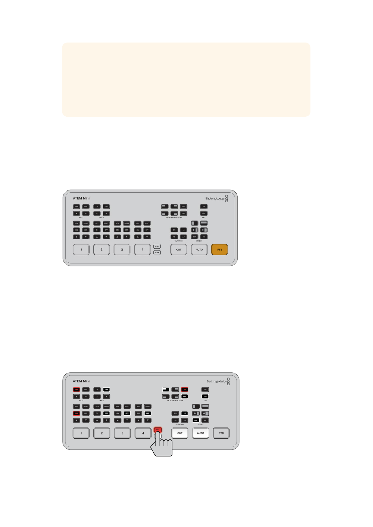
ATEM Mini’s control panel lets you switch video sources, adjust audio
levels, perform transitions and apply graphics and ef fects
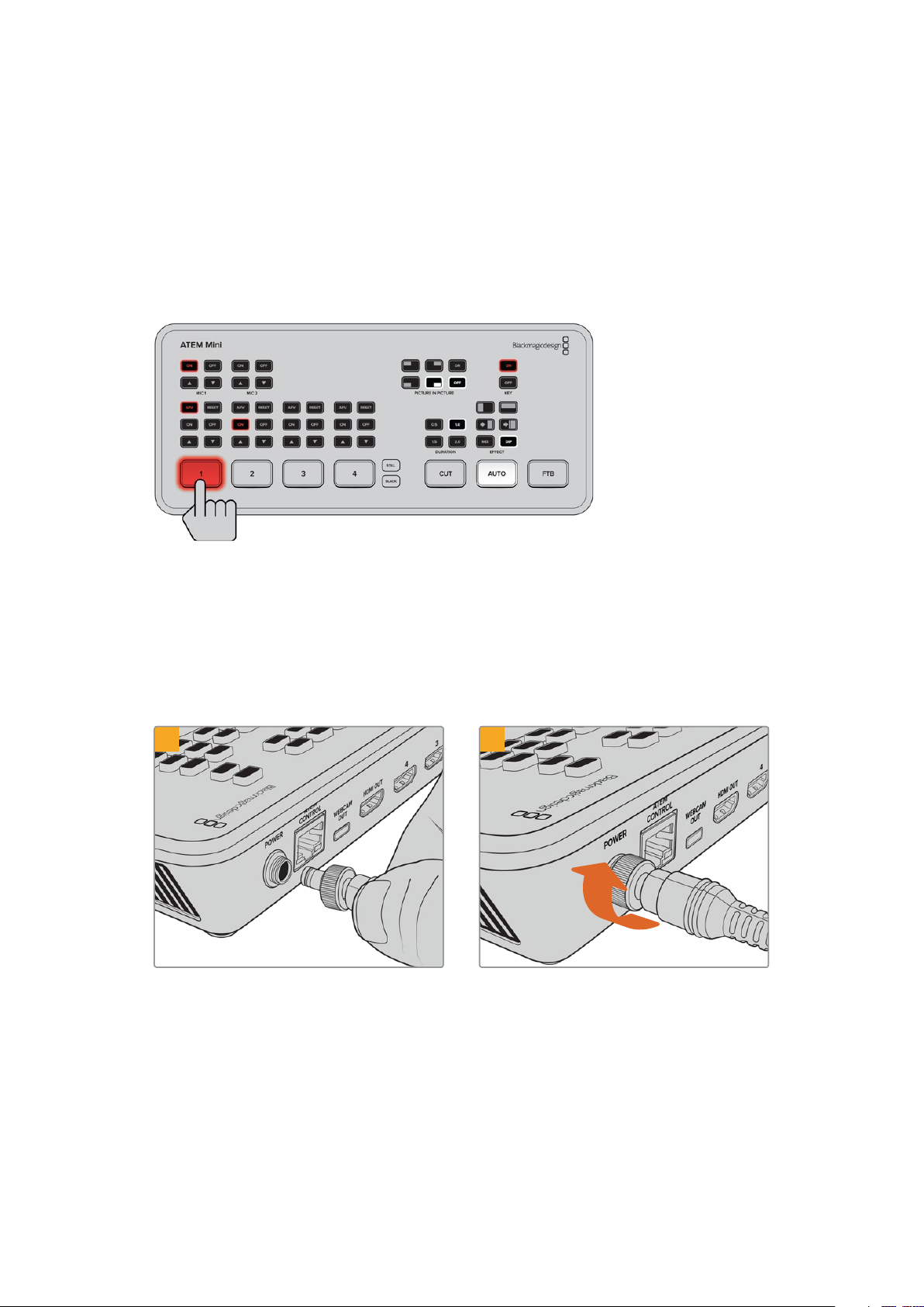
Plugging in Power
The first step to getting started is to plug in the mains power supply using the supplied power
adapter. Secure the connection to ATEM Mini by tightening the connector to the unit. This locks
the power cable to ATEM Mini preventing it from being accidentally removed.
1 2
Connec t power to ATEM Mini’s power
input using the supplied cable
Secure the connec tor to ATEM Mini by
tightening the connector screw
5Getting Started
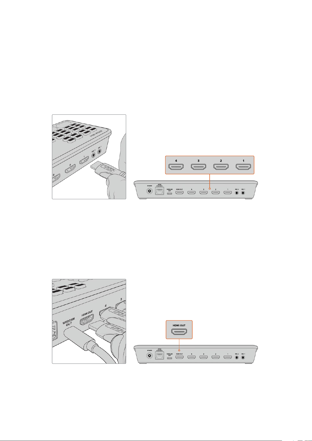
Plugging in Video Sources
Plug your HDMI cameras and other HDMI sources into ATEM Mini’s HDMI inputs. This gives you
four different images to switch to when creating your program. Simply plug one end of the
HDMI cable to your camera and the other end to any of ATEM Mini’s HDMI inputs. The first input
you plug in will set the video format, so if the first video source you plug in is 1080p50, all other
inputs will automatically be converted to 1080p50.
If you want to set the video format yourself after plugging in all video sources, you can do that in
the switcher settings in ATEM Software Control. You can find more information about changing
the video format settings in the ‘using ATEM Software Control’ section.
Plug HDMI sources into ATEM Mini’s four HDMI inputs
Plugging in a Monitor and Testing Inputs
With your video sources connected, you can now plug an HDMI television into ATEM Mini’s
HDMI output and check all the inputs are working. This is also a good opportunity to check
sources and see if your shots are smoothly switching between each other.
To check your sources, simply press the numbered input buttons on ATEM Mini’s control panel
and watch the HDMI television. If your sources are working correctly, you should see them
switch between each other when you press the input buttons.
Plug an HDMI television or monitor into ATEM Mini’s HDMI output so you can
monitor your program output and check all your sources are working properly
6Getting Started
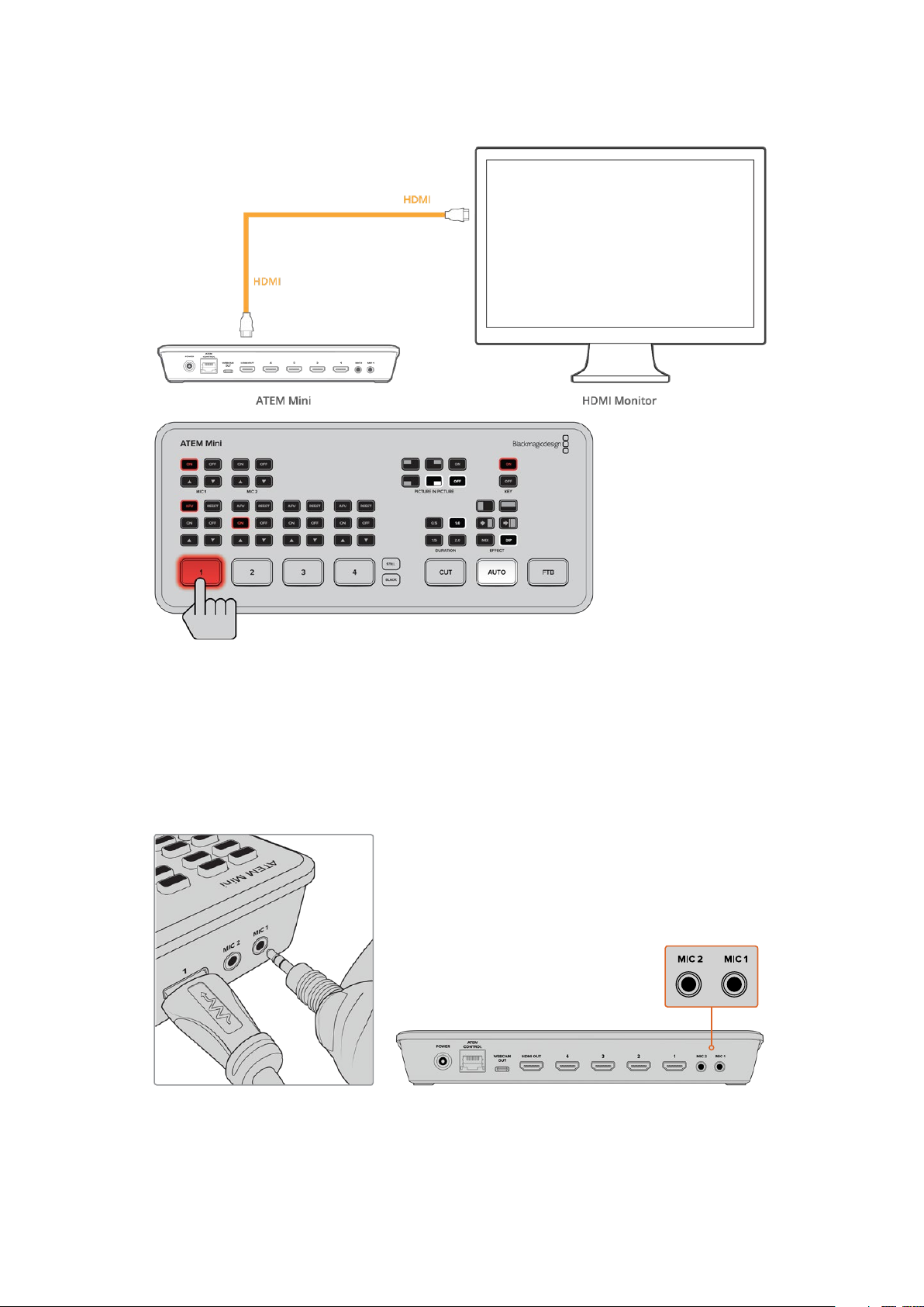
Connect a Microphone
When broadcasting a PowerPoint presentation or a kickstarter video, you might want to use a
microphone so your voice can be heard loud and clear. Plug a microphone, for example a small
wireless collar microphone, into one of the 3.5mm audio inputs.
If you are broadcasting an interview, plug the second microphone into the second 3.5mm
audio input. You can even plug a music player into one of the audio inputs and mix it into
your production.
Connect microphones to ATEM Mini’s mic inputs
7Getting Started
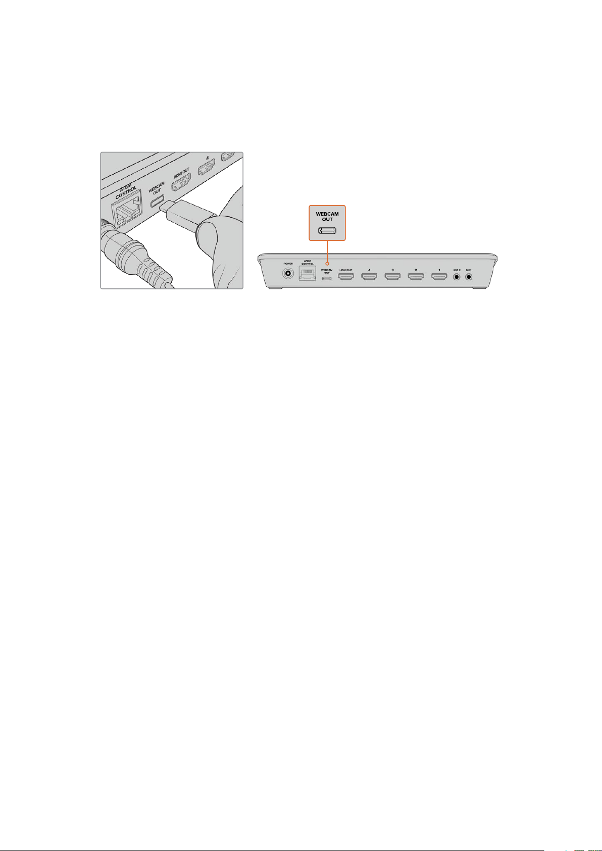
Connect your Computer
Plug ATEM Mini’s webcam output into your computer’s USB input. Now your computer will
recognize ATEM Mini as a webcam so you can select it as the webcam source in your streaming
program, such as Skype or OBS Studio.
Plug your computer into ATEM Mini’s webcam out USB-C connec tor
Setting the Webcam Source
In most cases, your streaming software will automatically set ATEM Mini as the webcam, so
when you launch your streaming software you will see the picture from your ATEM Mini
straight away. If your software doesn’t select ATEM Mini, simply set the software to use
ATEM Mini as the webcam and microphone.
Below is an example of how to set the webcam settings on Skype.
1 In Skype’s menu bar, open the ‘audio and video settings’.
2 Click on the ‘Camera’ drop down menu and select Blackmagic Design from the list.
You will see the video from ATEM Mini appear in the preview window.
3 Now go to the ‘microphone’ drop down menu and select Blackmagic Design as your
audio source.
With your Skype settings set correctly, perhaps try out a Skype call with a friend as a quick test
to check your broadcast setup is working.
That’s all you need to do and ATEM Mini is now ready to broadcast your video to the world live!
Using Open Broadcaster
Open Broadcaster is another streaming platform that takes your program video and streams it
live via your favourite video sharing application, like YouTube or Vimeo.
For information on how to set up Open Broadcaster with your ATEM Mini, refer to the ‘Setting up
Open Broadcaster’ section in this manual.
Switching your Production
Now that you have your cameras and microphone connected and your streaming software sees
ATEM Mini as a webcam, ATEM Mini is ready to start switching your production. This happens
when you switch from one video source in your broadcast to another. A source can be any
HDMI video signal connected to the HDMI inputs. It can also be a still graphic, a keyer, or any
internal source like a color generator, color bars, or black.
8Switching your Production
With ATEM Mini, you can switch cleanly using professional cuts or transitions. For example,
a cut will instantly change from one source to another and a transition will change sources over
a defined duration often using an effect. For more information, refer to the ‘using cuts and
transitions’ section later in this manual.
Using Cuts and Transitions
When switching video sources, you can use a straight cut which will immediately change one
source to another, or a transition which gradually changes one source to another over a defined
duration. Transitions appear as an effect, for example a cross dissolve or mix, a dip to colour, or
even a stylized wipe and you have many styles to choose from.
Switching Sources using a Cut
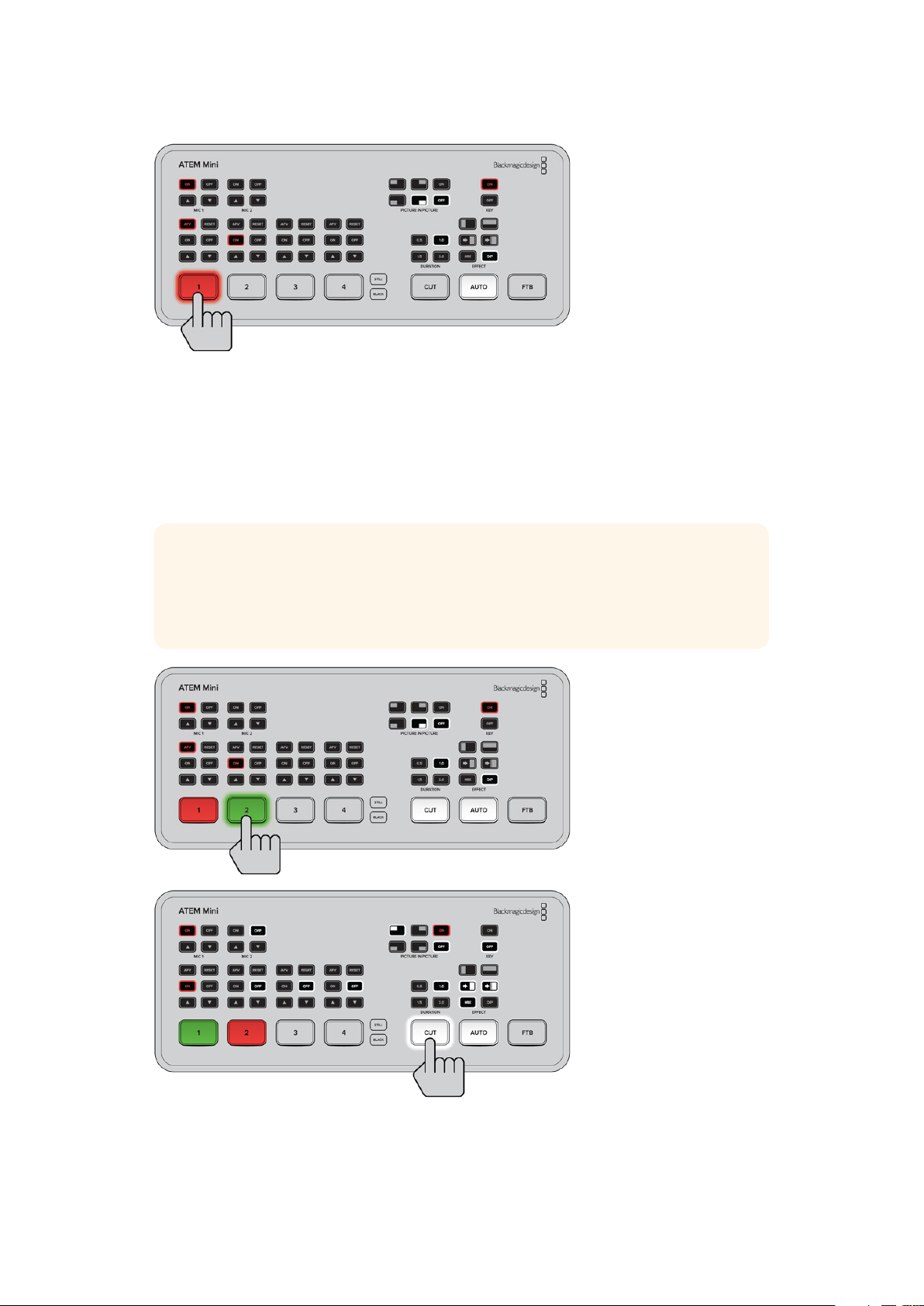
In the demonstration below ATEM Mini will cut from input 1 to input 2.
To perform a cut:
1 Input 1 is illuminated red to indicate input 1 is currently live on air.
2 Select a ‘cut’ by pressing the ‘cut’ button. Pressing ‘cut’ tells ATEM Mini
you want to use a straight cut instead of an auto transition.
3 Now press the input 2 button.
Input 1 will now immediately switch to input 2 and you will see input 2 illuminated red,
which means input 2 is now live on air. This is known as a cut as you are ‘cutting’ directly
from one source to another.
Switching Sources using an Auto Transition
Transitions let you smoothly switch from one source to another over a defined duration.
For example, a mix transition gradually fades the current source into the next until the original
source is no longer visible. For example, a wipe transition will move a line across the original
source revealing another effectively wiping across the image. You can add a colored border,
or make it soft so the edge is smooth and pleasing. You can even use digital video effects or
DVEs, such as a squeeze or push, to move the images as they transition from one to the other.
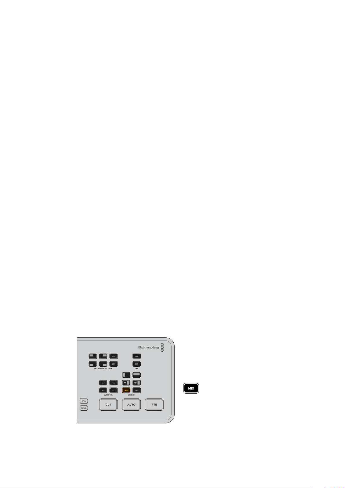
In the demonstration below ATEM Mini will switch from input 1 to input 2 using a mix transition:
To perform a mix auto transition:
1 Press the ‘mix’ button to select a mix transition.
9Switching your Production
2 Now press a duration you want for the mix.
3 Press the ‘auto’ button to tell ATEM Mini you want to use an automated transition.
4 Press the input 2 button to perform the mix transition.
You will now see inputs 1 and 2 buttons illuminated red while the transition happens and your
broadcast changes to input 2. When the transition is complete, input 2 will be illuminated red
to indicate it is now live on air.
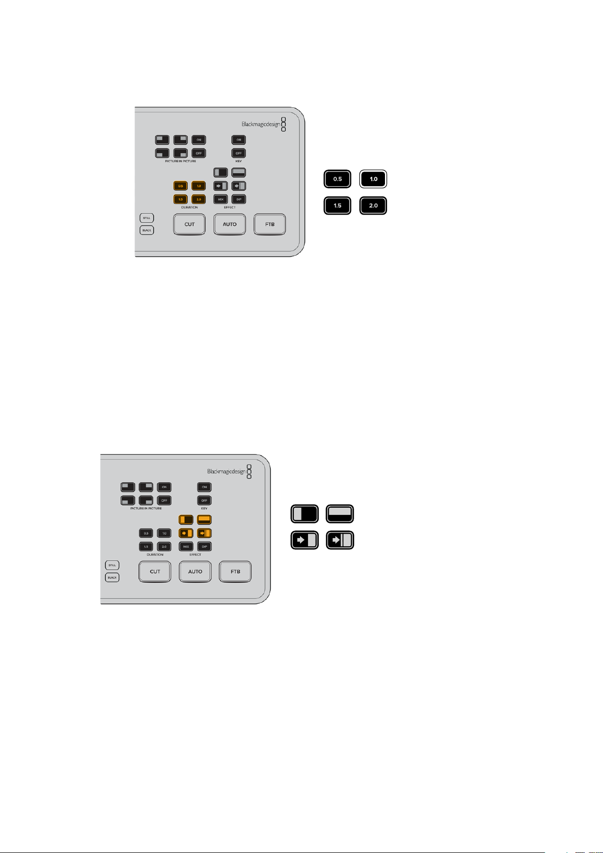
Transition Styles and DVEs
The buttons above the ‘auto’ button contain different transition styles, including a mix cross
dissolve and a dip to color.
You can also select horizontal and vertical wipe transitions by pressing their respective
transition style buttons. These also include DVE push and squeeze transitions.
Press the transition type button for the transition you
want to use, for example a horizontal or vertical wipe,
push or squeeze DVE transition, and mix or dip transition
Controlling Audio
When setting up your production or during your broadast, you will likely want to control audio
levels if the sound is too quiet or too loud.
When an audio level is too loud it will clip. Clipping means the audio has increased beyond the
maximum accepted level and when this happens it can distort and sound unpleasant.
10Switching your Production
Pressing the up and down arrow buttons for each input will increase or decrease the audio
level for the respective source. For example, if the presenter’s voice is too loud and risks
clipping, you can decrease the audio level by pressing the down button incrementally until
the level is safe.
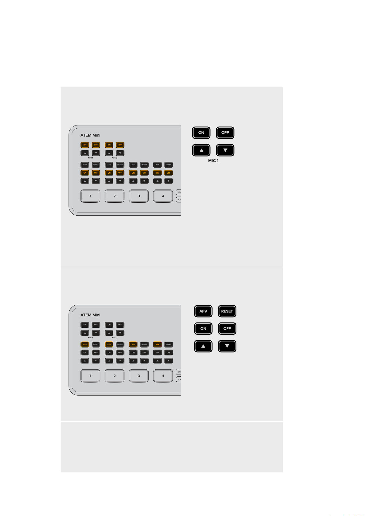
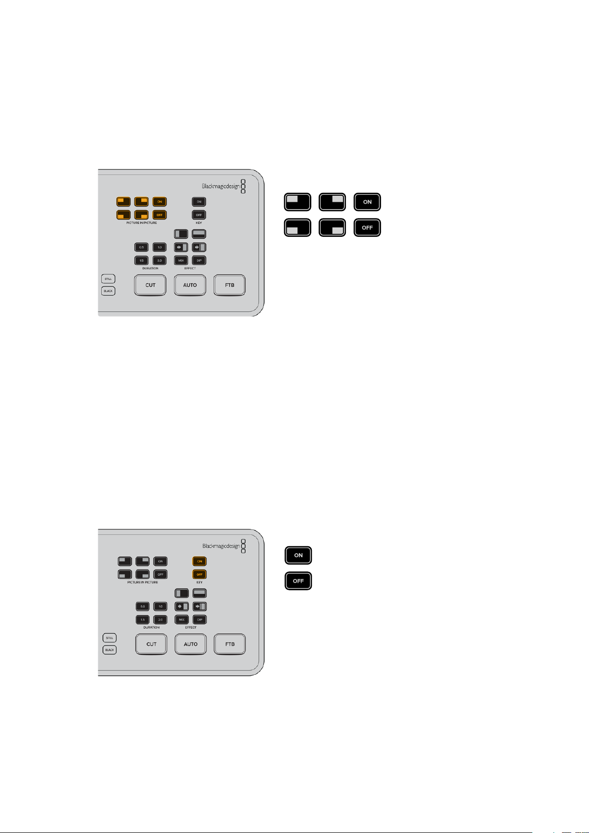
ON OFF
Pressing the on or off buttons will let you permanently enable the audio
from the respective input source, or turn its audio off completely.
ON – When the input’s audio is set to ‘on’, the input audio will be heard permanently,
even if the source is not currently on air.
OFF – When the input’s audio is set to ‘off’, the source audio will never be heard even if
the source video is on air.
AFV
AFV stands for ‘audio follows video’ and will let the audio for a respective input be heard
whenever the source is switched on air.
To enable or disable AFV for each input, simply press its AFV button.
Reset
Pressing the ‘reset’ button will restore the input audio level to its default position. This is
helpful if you want to cancel any adjustments or reference the original level before you
made changes.
11Switching your Production
Using Picture in Picture
Picture in picture superimposes a second source over your broadcast video source in a small
box you can position and customize. Input 1 is the default picture in picture source, so if you’re
broadcasting gameplay and want to superimpose your reactions, plug your camera into input 1
and it will appear in picture in picture.
To enable picture in picture:
1 Make sure your video to be inside the box is plugged into HDMI input 1.
2 Plug your main video into HDMI input 2, 3, or 4.
3 In the picture in picture buttons on control panel, press ‘on’.
You will now see the picture in picture box appear on the screen. To select a different position,
press any of the position buttons.
Using the Upstream Keyer
ATEM Mini’s upstream keyer is used to superimpose graphics or blend one video layer over
another using transparency. This means you can tell ATEM Mini to make an input source’s
background color invisible using the chroma keyer, or only use a specific section of a graphic
using a luma or linear key. Linear keys are great for visual effects, titles and lower third graphics.
Press the ‘key’ on or of f but tons to switch the
upstream keyer on and off air
12Switching your Production
TIP ATEM Mini’s advanced chroma keyer is perfect for keying graphics from a
PowerPoint presentation. For example, you could have a series of graphics designed
to be keyed over a background and these can played out directly from a PowerPoint
sequence. All you need to do is make any invisible areas green, or any solid color that
isn’t used in your graphic, then set the chroma keyer to make that color transparent.
The images from your computer will be high quality over HDMI so will key very cleanly
and look fantastic.
Fade to Black
The fade to black button is an easy way to start and end live broadcasts. Fade to black
performs a mix to black which happens across all video layers at the same time. This means all
video inputs, stills and any upstream or downstream keyers that are visible in your broadcast.
When performing a fade to black, the master program audio will also fade out to silence.
Simply press the FTB button to perform the fade to black. The button will flash while enabled.
To fade up from black, simply press the FTB button again. This is a clean way of starting and
finishing a broadcast.
Using a Still Graphic
The ‘still’ button is another input source you can switch to in your production. Simply press the
‘still’ button to switch a still loaded in the media player to air.
To take the graphic off air, simply switch to a different input source.
The ‘still’ button will switch a graphic loaded in ATEM Software Control’s media pool.
ATEM Software Control is an extremely powerful software control panel that opens a
world of options and lets you do a lot more with ATEM Mini.
13Switching your Production
ATEM Software Control
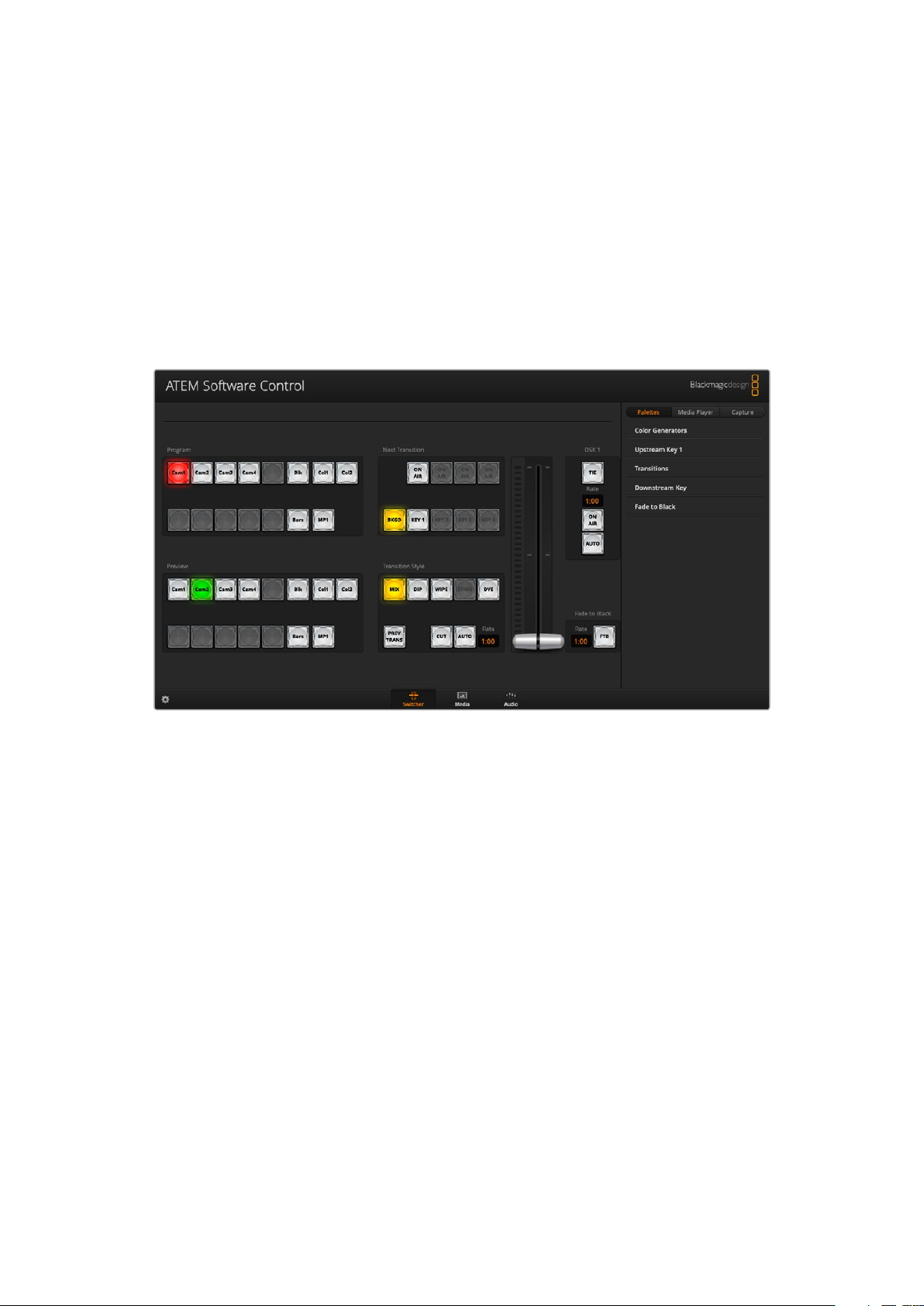
ATEM Software Control is a powerful software control panel that gives you a lot more control
over your ATEM Mini. Once you start using ATEM Software Control you will quckly see just how
much your ATEM Mini can actually do.
For example, you can manually perform transitions using the fader bar, select internal sources
on the program and preview buttons, mix audio using a mixer with channel faders, set up
keyers, load graphics in the media pool and much, much more.
ATEM Software Control is included with your ATEM Mini and allows you to control your switcher
in a similar way to a full hardware control panel. A range of palettes on the right side shows you
all processing features of your ATEM Mini and allows settings to be easily made.
You can also use ATEM Software Control to configure your switcher settings. For more
information on how to use ATEM Software Control, refer to ‘using ATEM Software Control’
in the following sections of the manual.
Switching Modes
‘Cut bus’ is the default switching mode which lets you change sources as soon as you press an
input button. Setting ATEM Mini to ‘program preview’ mode lets you preview the source before
switching it to air.
Cut Bus
In cut bus mode, as soon as you press an input button, it will immediately switch to air.
This is a fast and easy way of switching.
14Switching your Production
In cut bus mode, pressing an input but ton will instantly switch it to air
Program Preview
In program preview mode, switching a source is a two step process. This is because pressing
an input button puts the source in a preview state so you can decide whether you want to
switch it, or perhaps select a different input source. This powerful switching mode is used by
professional broadcast switchers across the world.
TIP If you connect an HDMI monitor, for example Blackmagic Video Assist, to
ATEM Mini’s HDMI output you can output the preview signal and monitor the
selected input before switching it to air. For more information, refer to the ‘setting
the HDMI output’ section later in this manual.
In program preview switching mode, press an input button and then
press the ‘auto’ or ‘cut’ button to switch the source to air
15Switching your Production
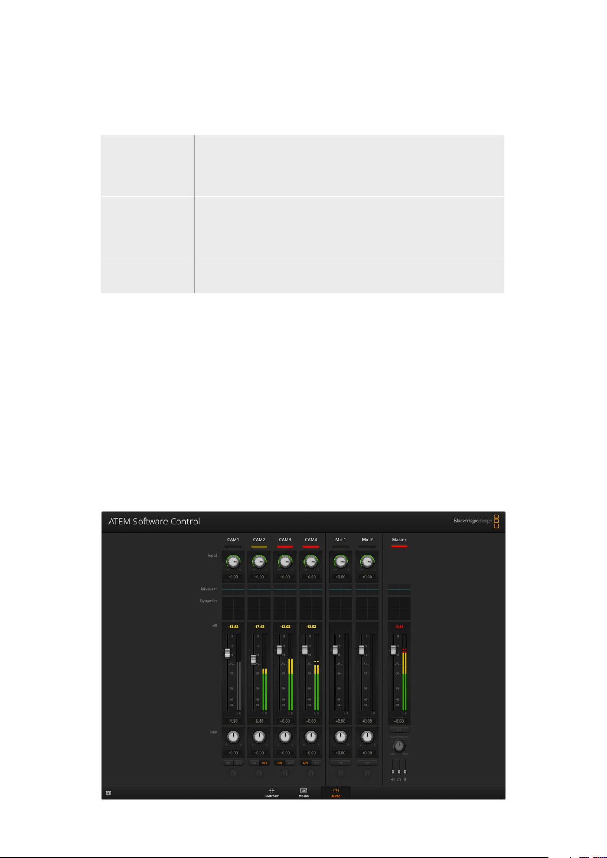
Using ATEM Software Control
ATEM Software Control has three main control windows: Switcher, Media and Audio. You can
open these windows by clicking the three main buttons at the bottom of the interface or by
pressing the Shift and left/right arrow hot keys. A general settings window can be opened by
selecting the gear icon at the lower left of the interface.
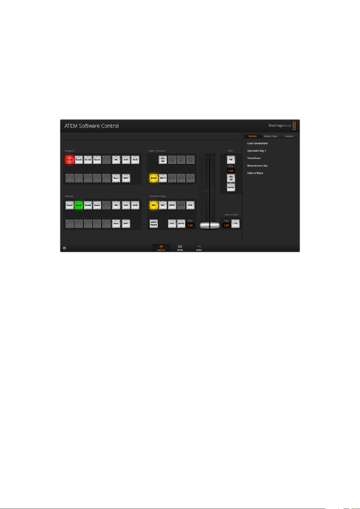
Switcher Panel
When first launched, the switcher screen is selected, which is the main control interface for
the switcher. ATEM Mini must be connected to your computer via USB for the software control
panel to run.
Mouse or Trackpad Operation
The virtual buttons, sliders and fader bar on the software control panel are operated using your
computer mouse or a trackpad if you’re using a laptop.
To activate a button, click once with the left mouse button. To activate a slider, click and hold
down the left mouse button while dragging. Similarly, to control the fader bar, click and hold
down the left mouse button on the fader bar handle and drag up or down.
Media Manager
The media manager allows you to upload graphics to the media pool in ATEM Mini. Your
ATEM Mini has memory for graphics that’s called the media pool and holds up to 20 still
graphics with alpha channel that can be assigned to a media player for use in your production.
So, for example, you could have the maximum 20 still graphics loaded that will be used on your
live production and then assign various stills to the media player as you work. As you take a
graphic off air, you can change the media player graphic to the next graphic you want, and then
you can put that media player back on air with the new graphic.
When a still is loaded into the media pool, the alpha channel is loaded automatically if one is
included in the image. When a still is loaded into a media player, the output of the media player
will include both key and fill outputs. If you select the media player as a key source, for example
Media Player 1, both the fill and the key are automatically selected so you don’t have to select
16Using ATEM Software Control
them separately. However the key can still be routed separately so you can use a different
key source if you wish. To learn more about keying, refer to the ‘keying using ATEM Mini’
section of this manual.
Audio Mixer
The audio tab in ATEM Software Control contains a powerful audio mixer interface which
becomes active when controlling your ATEM switcher.
ATEM Mini includes a built in audio mixer that lets you use the embedded HDMI audio from your
cameras, media servers and other inputs without the need for an external audio mixer. This is
perfect when using your ATEM Mini on location or in small spaces within modern OB vehicles as
you don’t have to find room for an external audio mixer. The audio is mixed in the audio tab of
ATEM Software Control and output via the USB webcam output. You can also route the program
output via HDMI if you want to record your broadcast.
Your ATEM Mini also features built in mic inputs for mixing external audio.
If you prefer to use an external audio mixer, it’s easy to disable the audio for all inputs and you
only need to leave the external audio active in the audio mixer interface. More information on
how to use the audio mixer is included in the next sections.
Using the Software Control Panel
The switcher window is the main control interface for the switcher. During live production,
theswitcher window can be used to select sources and take them to air.
You can select the transition style, manage upstream/downstream keyers and turn on/off the
fade to black. The palettes on the right hand side of the interface are where you adjust
transition settings including transition rates, adjust color generators, control the media player,
andadjust the upstream and downstream keyer as well as control fade to black rate.
17Using ATEM Software Control
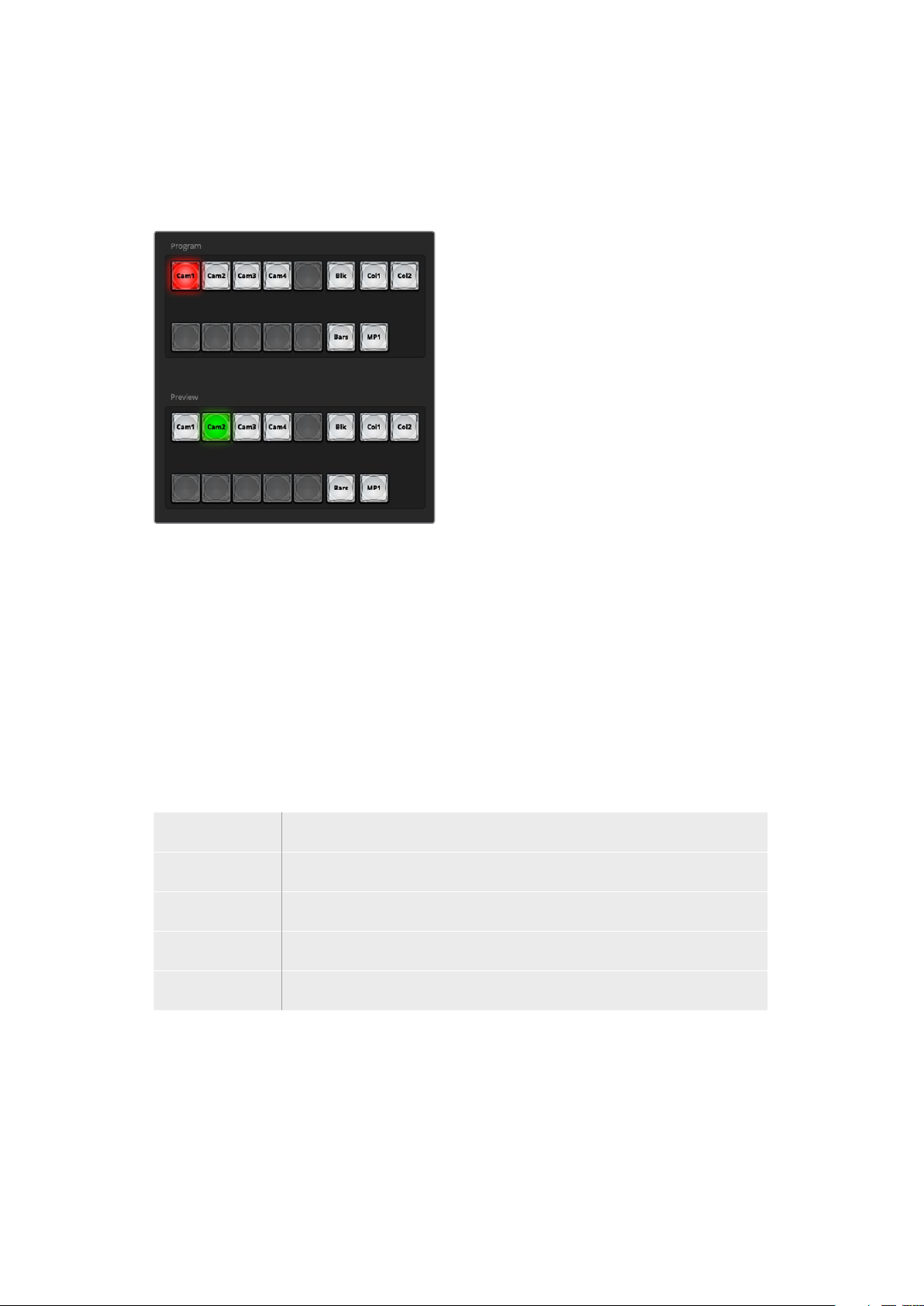
Mix Eects
The Mix Effects block of the switcher tab contains all the source select buttons for the program
and preview buses, allowing external inputs or internal sources to be selected for next
transition previewing or switching to air.
ATEM mix effects
Program Bus Source Select Buttons
The program bus source select buttons are used to hot switch background sources to the
program output. The source currently on air is indicated by a button that is illuminated red.
Preview Bus Source Select Buttons
In program preview switching mode, the preview bus source select buttons are used to select a
background source on the preview output, this source is sent to the program bus when the next
transition occurs. The currently selected preview source is indicated by a button that is
illuminated green.
The source select buttons for the program bus match the preview bus.
INPUTS Input buttons match the number of external switcher inputs.
BLACK Black color source internally generated by the switcher.
BARS Color bars source internally generated by the switcher.
COLOR 1 and 2 Color sources internally generated by the switcher.
MEDIA 1 Internal media player that display stills stored in the switcher.
18Using ATEM Software Control
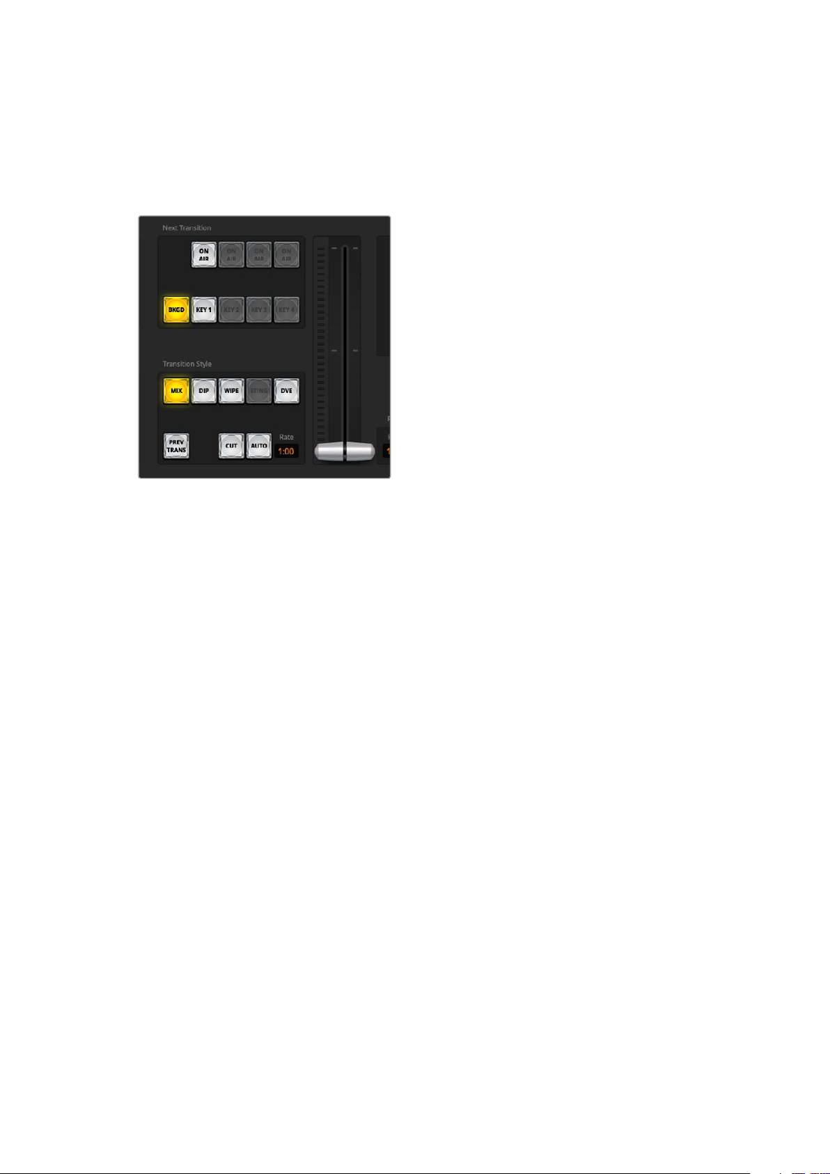
Transition Control and Upstream Keyer
CUT
The CUT button performs an immediate transition of the program and preview outputs,
overriding the selected transition style.
Transition control
AUTO/RATE
The AUTO button will perform the selected transition at the rate specified in the ‘rate’ display.
The transition rate for each transition style is set in the transition palette for that style and is
displayed in the ‘rate’ window of the transition control block when the corresponding transition
style button is selected.
The AUTO button illuminates red for the duration of the transition and the ‘rate’ display updates
to indicate the number of frames remaining as the transition progresses. When you perform a
transition using the fader bar on an external ATEM hardware panel, the fader bar indicator on
the software panel updates to provide visual feedback on the progress of the transition.
Fader Bar
The fader bar is used as an alternative to the AUTO button and allows the operator to manually
control the transition with a mouse. The AUTO button illuminates red for the duration of the
transition and the ‘rate’ display updates to indicate the number of frames remaining as the
transition progresses.
Transition Style
The transition style buttons allow the operator to select one of four types of transitions; mix,
dip, wipe and DVE. The selected transition style is indicated by a yellow illuminated button.
Selection of these buttons will be reflected by the corresponding tab in the ‘transitions’
processing palette. For example, when you have the transitions processing palette open and
click on a transition style button, the transitions palette will match your selection so you can
quickly adjust the settings.
PREV TRANS
The PREV TRANS button enables the preview transition mode, allowing the operator to verify
a mix, dip, wipe or DVE transition by performing it on the preview output using the fader bar.
When the PREV TRANS is selected you will see the preview output match the program output,
and then it’s simple to practice your selected transition with the fader bar to confirm you are
going to get what you want. This is a very helpful feature to avoid mistakes on air!
19Using ATEM Software Control
Next Transition
The BKGD and KEY 1 buttons are used to select the elements which will transition on air or off
air with the next transition. More upstream keyers are available on 4K model ATEM switchers
and that is why other upstream keyers appear greyed out. The key can be faded on and off
when the main transition occurs, or you can select just the key to transition individually, so the
main transition control can be used to fade the key on and off.
When selecting the elements of the next transition, the switcher operator should look at the
preview video output because it provides an accurate representation of what the program
output will look like after the transition is completed. When only the BKGD button is selected,
a transition from the current source on the program bus to the source selected on the preview
bus will occur without the keyer. You can also select only keyer to transition, leaving the current
background live throughout the transition.
ON AIR
The ON AIR indicator button indicates when the key is currently on air and can also be used to
immediately cut the key on or off air.
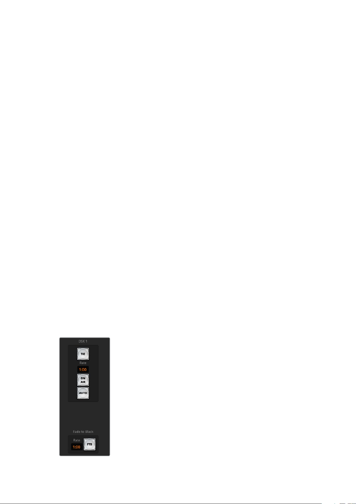
Downstream Keyer
TIE
The TIE button will enable the downstream keyer, or DSK, on the preview output, along with the
next transition effects and tie it to the main transition control so that the DSK can be taken to air
with the next transition.
The DSK will transition at the rate specified in the ‘rate’ display of the transition control block.
If the DSK is tied, the signal routing to the clean feed 1 is unaffected.
ON AIR
The ON AIR button is used to cut the DSK on or off air and indicates whether the DSK is
currently on or off air. The button is illuminated if the DSK is currently on air.
AUTO
The AUTO button will mix the DSK on or off air at the rate specified in the DSK ‘rate’ window.
This is similar to the main AUTO rate on the transition control block, however it’s limited only to
the downstream keyer. This can be used to fade up and down bugs and logos, such as live or
replay bugs during production, without interfering with the main program production transitions.
Fade to Black
Downstream key and fade to black
20Using ATEM Software Control
The FTB button will fade the whole program video output to black at the rate specified in the
fade to black RATE window. Once the program output has been faded to black, the FTB button
will flash red until it is pressed again. Doing so will fade up from black at the same rate, or you
can enter a new rate in the fade to black palette in the ‘switcher’ window. Fade to black is
mostly used at the start and end of your production, or when cutting to commercial breaks. It
ensures all layers in ATEM Mini are faded down together. A fade to black cannot be previewed.
You can also set the audio mixer to fade the audio with your fade to black by selecting the
‘audio follow video’ checkbox in the fade to black palette, or by enabling the AFV button on the
master audio output fader.
Processing Palettes
The software control panel features tabs for the processing palette, media player, and capture
options. The capture option supports legacy model ATEM switchers with USB capture features.
TIP The palettes also show the order of the processing in the switcher. You can
expand and minimize palettes to save space and scroll them up and down to get the
adjustments you need to set.
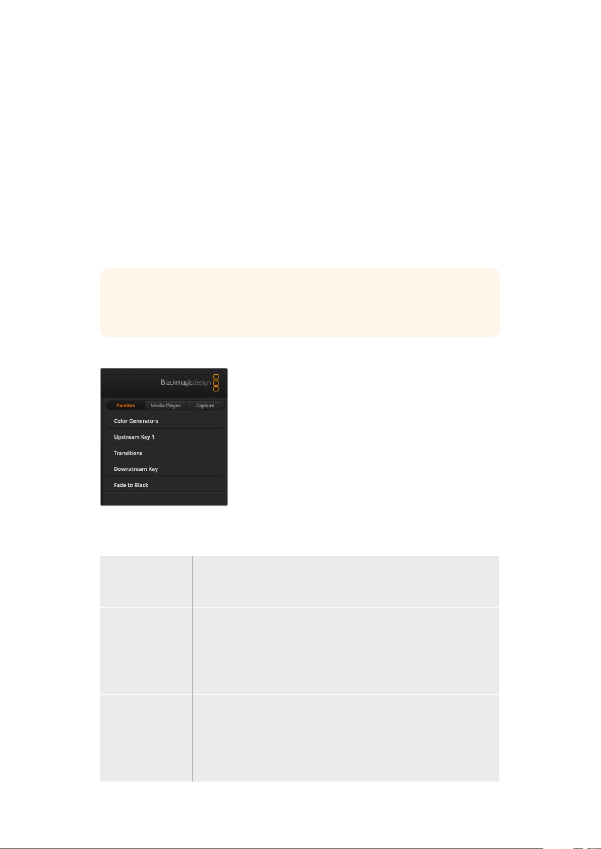
The following processing palettes are available.
Palettes Tab
The ‘palettes’ tab contains the following processing controls.
Color Generators Your ATEM switcher has two color matte generators which can be configured
from the color generators palette using a color picker or by setting hue,
saturation, and luminance levels.
Upstream Key The switcher’s upstream keyer can be configured from the upstream key
palette. Within the keyer palette, the keyer can be configured as a luma key,
chroma key, pattern key or DVE. The type of key available will also depend
on if the DVE is available. The upstream key palette will display all the
parameters that are available to configure the keyer. More information on
how to use upstream keyer is included later in this manual.
Transitions The transitions palette is where you can configure the parameters of each
transition style. Forexample, for the dip transition the palette has a drop
down menu where you can select the dip source and for the wipe transition
the palette displays all the available wipe patterns. There are lots of
variations of transitions, and a large number of transitions can be created by
combining settings and features in the transitions palette.
21Using ATEM Software Control
NOTE It’s worth noting that simply selecting a specific style of transition in this palette
will only adjust the settings for these transitions, and you still need to select the style
of transition you want to perform in the transition control section on the software or
ATEM Mini’s control panel. The software and ATEM Mini’s control panel work together
and mirror all settings, so you can use any combination you like!
Downstream Key ATEM Mini has a downstream keyer which can be configured from the
downstream key palette. The palette has drop down boxes for selecting the
fill and key signals to the keyer, plus sliders to set the pre multiplied key clip
and gain values, and mask settings.
Fade to Black The fade to black palette is where you can set the fade to black transition
rate. An ‘Audio Follow Video’ checkbox is also provided as a shortcut for the
audio mixer’s master fader AFV button. Selecting this feature lets you fade
your audio with your fade to black.
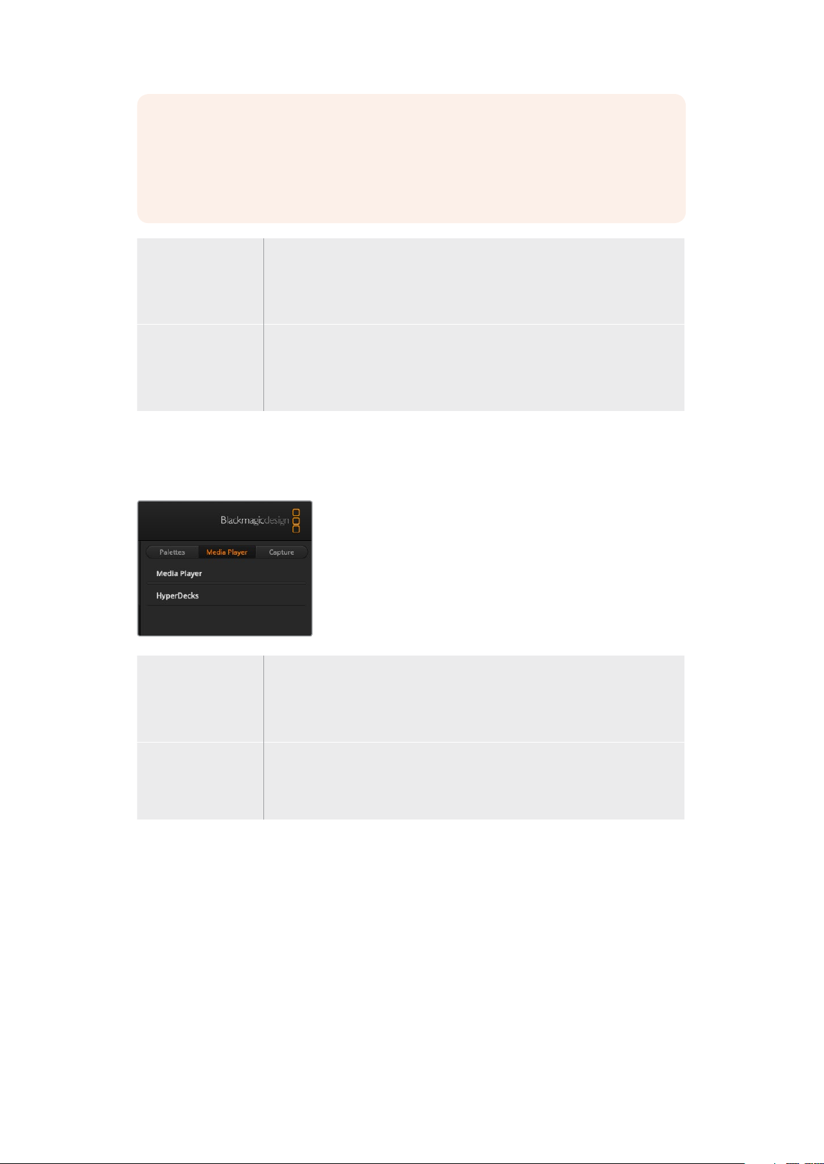
Media Player Tab
The ‘media player’ tab contains controls for your ATEM Mini’s media player and connected
HyperDecks.
Media Player Your ATEM Mini has a media player that plays back the stills that are stored in
the media pool memory built into the switcher. The drop down list is used to
select the still that will be played or made available on the media player input
to the switcher.
Hyperdecks You can connect up to 4 Blackmagic HyperDeck Studio model disk recorders
and control them using ATEM Software Control’s HyperDecks palette.
For more information refer to the ‘HyperDeck Control’ section of this manual.
Capture Tab
The capture tab supports the original ATEM production switchers that feature
USB output recording.
The capture tab lets you capture stills and set the timecode window.
Capture Still
If you need to capture a still image from your broadcast simply click on the ‘capture still’ button.
This acts like a still store which lets you add capture files to the media pool. You can then
immediately load a still into the media player and use it in your broadcast, or save the media
pool to your computer.
22Using ATEM Software Control
To save the media pool:
1 Go to the menu bar at the top of your screen and click on ‘file/save as’.
2 Choose the location you want to save to.
3 Click ‘save’.
Now that your media pool is saved on your computer, you can access the captured stills and
use them in your graphics software.
Timecode
The timecode window provides a timecode counter that runs from the moment you power your
ATEM Mini. The counter can also be set manually.
To set the counter:
1 Click on the ‘set timecode’ edit box underneath the counter. An orange border will
appear when the box is enabled.
2 Type in a manual timecode.
3 Click the ‘set’ button.
The counter will now run timecode from your manually set values.
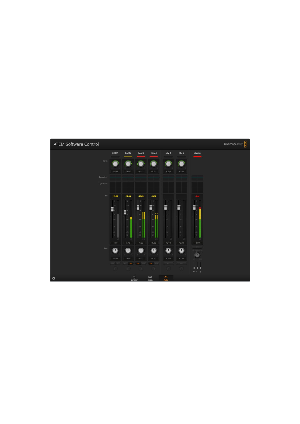
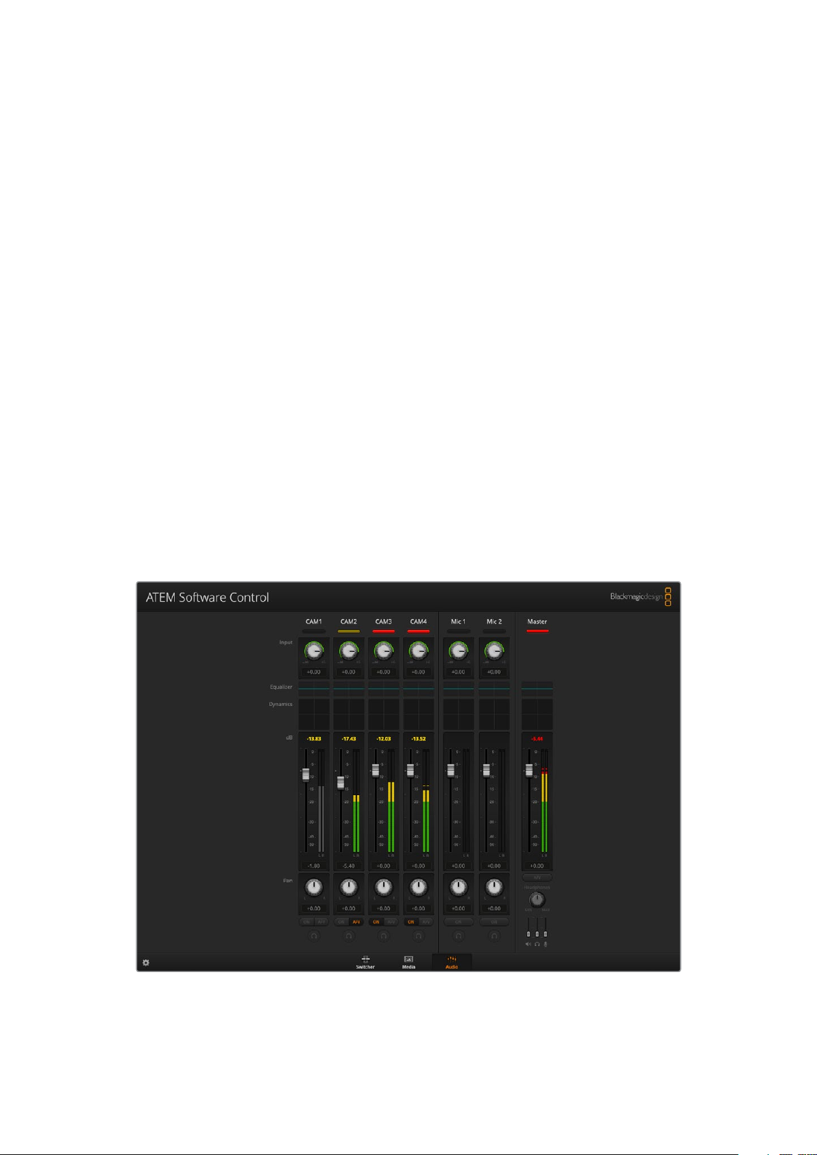
Using the Audio Mixer
The audio tab is used to mix audio sources connected to ATEM Mini via HDMI and mic audio.
Cameras and external mic audio sources are listed along the top of the audio mixer along with
the master audio output for the USB webcam program output to your computer.
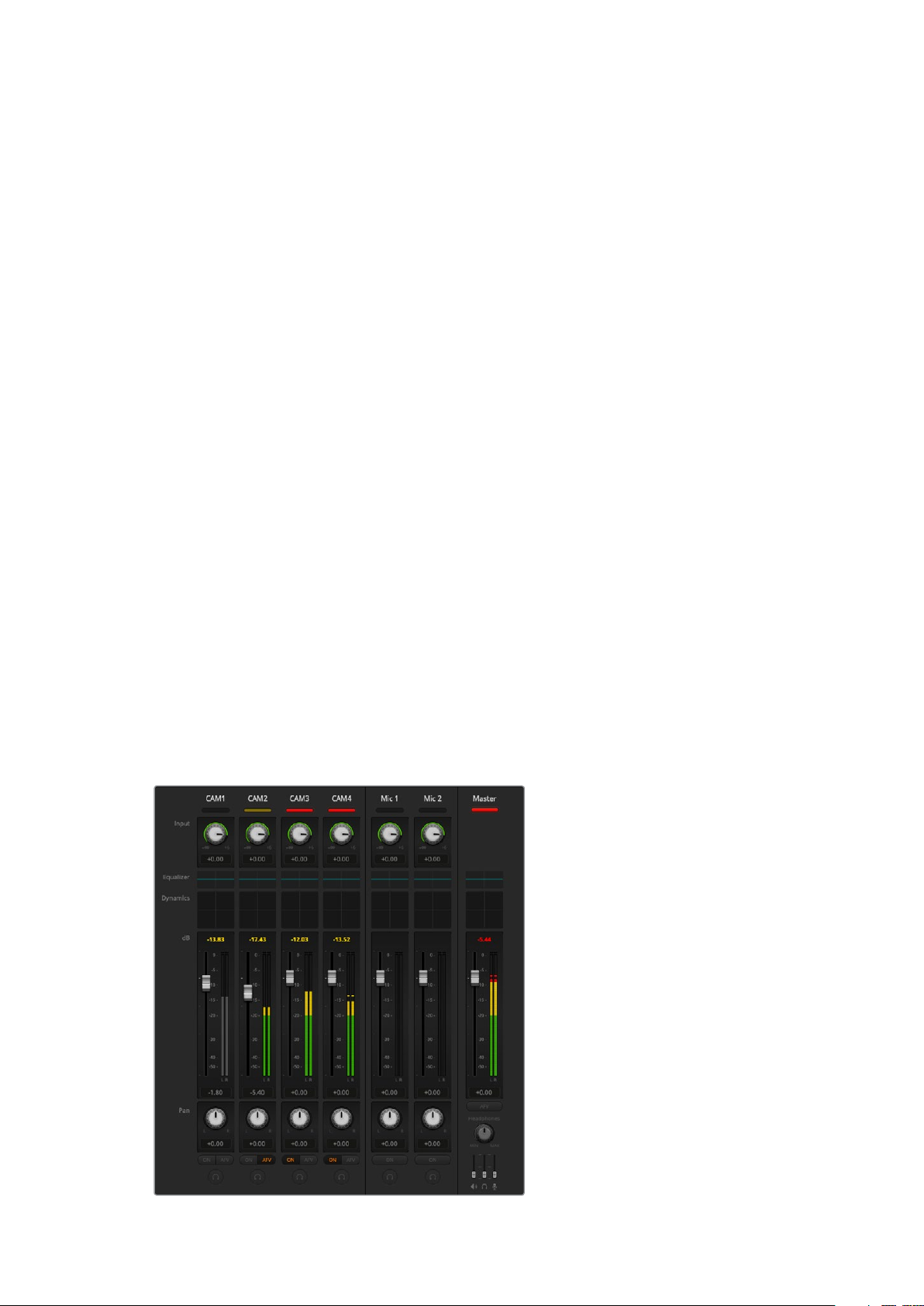
The audio mixer displays tally lights for any audio sources that are currently on air or when AFV is
selected, as well as audio level, audio balance and buttons for selecting which audio should be used
23Using ATEM Software Control
Below each audio source is an audio level meter, a fader for setting the maximum audio level,
and a knob for setting the left/right audio channel balance. The master fader on the right side of
the audio mixer is used to set the gain on the audio level on the USB webcam program output
and has its own audio level meter. Next to the master fader are mic faders which let you control
the audio level for microphones connected to the mic inputs.
The buttons below each audio level meter determine whether audio is always available for
mixing or only when the source is on air.
The solo monitoring feature for each input is greyed out as it supports ATEM Production Studio
and Broadcast Studio model switchers.
Tal l y
Any source whose audio is on air is lit with a red tally light in the software. In the example on
this page, camera 3 and camera 4 are lit because their audio is set to be always on. The tally
light will be illuminated dull yellow when AFV is selected and the channel’s associated camera
is off air. This also applies to the master fader tally light when the master fader AFV button is
selected. When FTB is activated, the master fader tally light will blink red.
Audio Level
Drag the audio level fader to set the gain on the audio level for each camera and audio source.
The numbers under each audio level meter show the maximum audio level set by the fader.
The numbers above the audio meter show the peak audio level reached by the audio source.
A green number represents low to medium audio levels.
If the audio meter is regularly showing red, and the red number above it is not changing, then
you should reduce the audio level to avoid audio distortion. After adjusting the audio level, you
may wish to reset the red number by clicking on it once. Observe the new number to make sure
it changes for a while and does not immediately shoot up and become stuck on a red number.
If it does, you may need to reduce the audio level even further.
Audio Balance
The audio mixer supports stereo audio from each audio source. If you wish to change the left
and right audio channel balance for a camera or other audio source, adjust the knob to the
desired balance point.
The audio meter for Cam1 is shown in
gray to indicate that its audio will not be
used as neither of its ON or AFV buttons
are enabled. Cam2 has AFV selected
but its audio is not currently being used
as the camera is not on air as is indicated
by its dull yellow tally light. Cam3 and
Cam4 have their direct mix set to ON
so their mixed audio is always used and
their tally lights remain lit, even if another
camera is currently on air. The audio
level meters for Mic 1 and Mic 2 show
that no audio is present on these inputs.
24Using ATEM Software Control
Audio Source Selection
Below each audio level meter, you will find the ON and AFV buttons that select which audio
sources are sent to the program output of the switcher.
ON Selecting the direct mix to ON allows an audio input to be permanently
mixed into the program output, even when the associated video source is not
on air. The red tally light will always be lit because the audio is always on air.
Selecting this option automatically disables AFV.
Audio Follow Video Audio follow video allows audio to crossfade when inputs change. The audio
will only be sent to the program output when the input is on air, lighting the
red tally light above. When off air, the tally light is lit dull yellow. Selecting this
option automatically disables the direct mix ON setting.
SOLO The solo feature appears as a headphones icon below each input and is
available for ATEM Production Studio and Broadcast Studio model switchers.
Master Audio Level Output
The master fader on the right side of the audio mixer is used to set the gain on the audio level
for the USB webcam program output and has its own audio level meter. Select the AFV button
on the master audio output fader to enable the AFV fade to black feature. This lets you fade
your master audio when you click on the fade to black button.
Audio Mixer Monitor
The monitor headphones sliders appear below the master fader and control the monitoring
audio output behavior on ATEM Television Studio model switchers.
Shaping your Audio Mix using Advanced Fairlight Controls
ATEM Mini has advanced Fairlight audio controls that let you enhance and refine the quality of
sound on each input and master output, including input level controls, a 6 band parametric
equalizer and powerful dynamics settings.
25Using ATEM Software Control
This section of the manual shows the different Fairlight audio controls you can use to shape and
optimize the audio mix in your live production.
Input Level
Generally, when setting up your audio mix, the first step is to normalize all your inputs. This
means adjusting the input level knob on each input so you can optimize all the levels to their
highest strength without clipping.
This control is at the top of each track under the tally light. Change the level by clicking on the
knob and dragging left to decrease the level, or right to increase. By setting the input control,
itbrings all the inputs up to a common signal strength so they are all at their strongest without
clipping.
After you have normalized all your input levels, you can now begin optimizing and shaping the
qualities in each audio input using the6 band parametric equalizer and dynamics controls.
Using the 6 Band Parametric Equalizer
Each input and the master output has a 6 band parametric equalizer which can be used to
control specific frequencies. This could include reducing low frequency hum or noise on a
microphone input, or boosting the low frequencies on a thin sounding track, or even to add
uniqueness to each input so they are more distinct in the final mix. You have many
creative options.
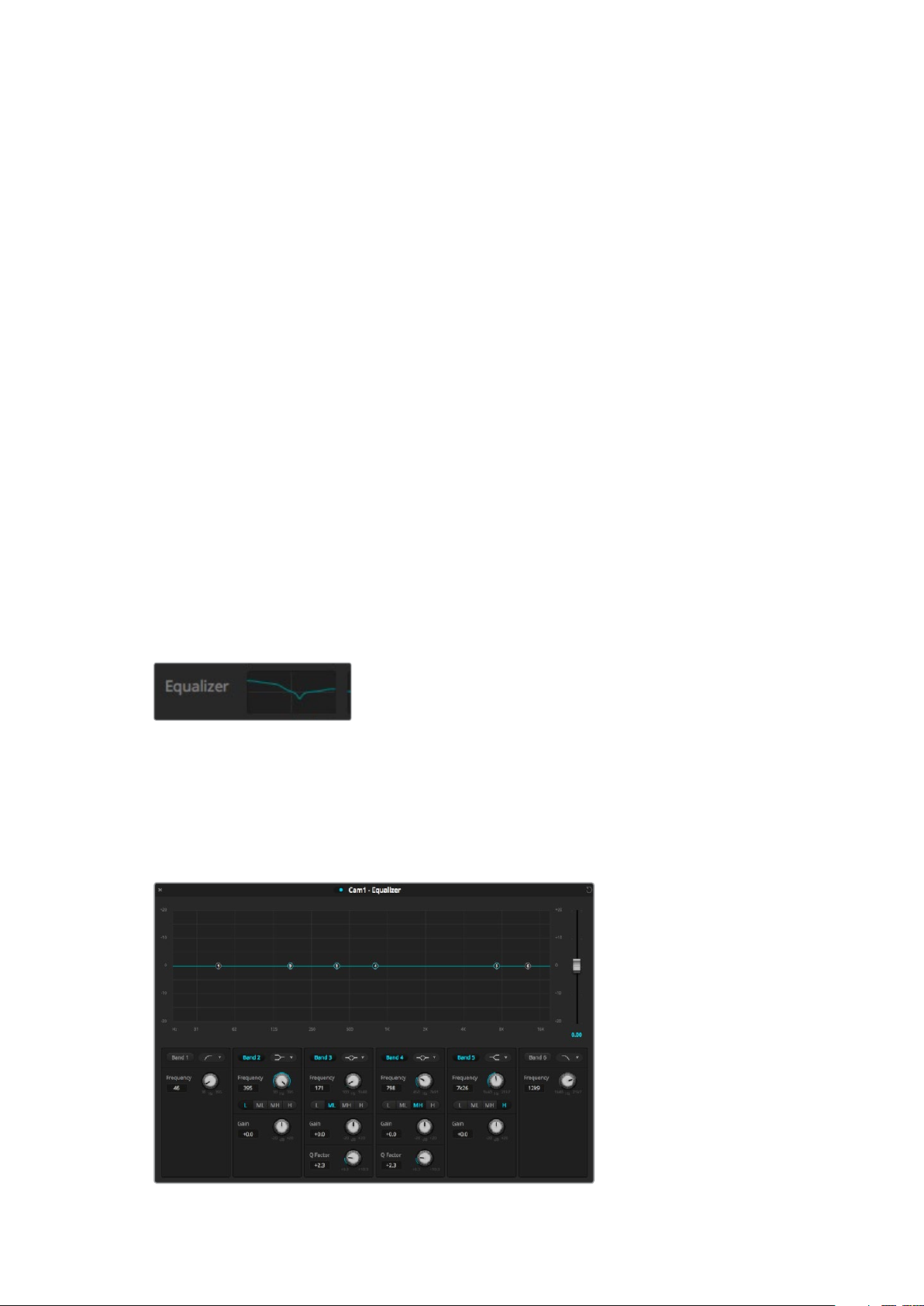
Parametric Equalizer
To open the parametric equalizer for an input or the master output, click on the corresponding
equalizer indicator.
Click on an input’s equalizer indicator to
open a 6 band parametric equalizer
The first item you will notice is the graph along the top of the window with numbered indicators
from 1 to 6. These numbered indicators are adjustable handles that correspond to bands 1 to 6.
Each band of the 6 band parametric equalizer has a column of settings. These settings will
differ based on which band you are controlling, and what filter type you are using.
Each audio input has its own 6 band parametric equalizer
26Using ATEM Software Control
TIP You can learn more about band filters later in this section.
If you want to make changes to a setting, you will first need to make sure the band is enabled.
Click on a band label to enable it. When enabled, the button label is illuminated blue. Now you
can change the settings for that band, or click and drag the handles to make fast adjustments.
Handles
Each band handle is positioned along the line curve displayed in the graph. You can click and
drag each handle to choose the frequency you wish to adjust for that band, and the gain you
want to set. When moving a handle with your mouse, both the frequency and gain settings are
affected simultaneously, which gives you a fast way to make quick adjustments to each band
across the entire range of frequencies.
NOTE To make changes using a handle, ensure the band is enabled. Simply click on
the band you want to adjust. The band label will illuminate blue when enabled.
As you drag a handle left or right, you will notice the frequency and decibels update in the band
settings. This will also be reflected by the frequency range preset buttons for low, medium low,
medium high, and high.
Frequency Knobs
Alternatively, you can use the frequency knobs for each band to select a specific frequency
to adjust.
Range Presets
The frequency range for each band is defined by the range preset buttons. For example, low is
labeled ‘L’ and covers the frequency range from 30 to 395 Hz.
As a quick example of how the range presets define the frequency range, select a notch filter
from the band f ilter dropdown list, and then click on each range preset. You will see the filter
effect move to a position along the graph curve that corresponds to the range preset you
choose. This lets you quickly define aspecific range of frequencies you want the filter to affect.
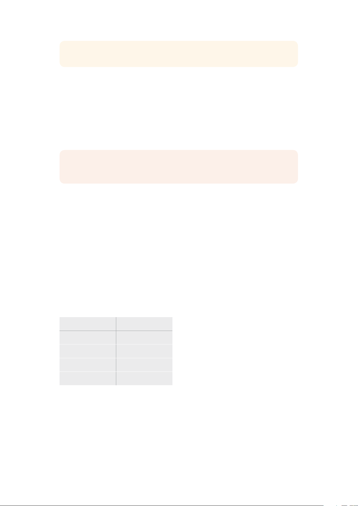
Below is a table showing the range of frequencies for each range preset setting.
Range Preset Frequency Range
Low 30 Hz to 395 Hz
Mid Low 100 Hz to 1.48 kHz
Mid High 450 Hz to 7.91 kHz
High 1.4 kHz to 21.7 kHz
Gain Knobs
Click and drag the gain knob left or right to decrease or increase the volume level for the
selected frequency.
27Using ATEM Software Control
Q Factor
The Q factor control is available when the bell filter is applied to bands 2, 3, 4 and 5. This sets
the range of frequencies the filter will affect. For example, setting the minimum will allow the
filter to affect a wide range of surrounding frequencies and the maximum setting will narrow
theeffect down to a tiny point. This is important if you have sound qualities in surrounding
frequencies that you want to either include or exclude from the change you are making.
As you adjust the Q factor, watch the shape of the effect on the line curve change from a broad,
rounded edge to a sharp point. This is a visual representation showing how the regions of
frequencies surrounding the target frequency are affected.
TIP Compare the audio with changes against the original unaltered audio by clicking
on the bypass button at the very top of the equalizer window. This lets you turn the
equalizer on or off.
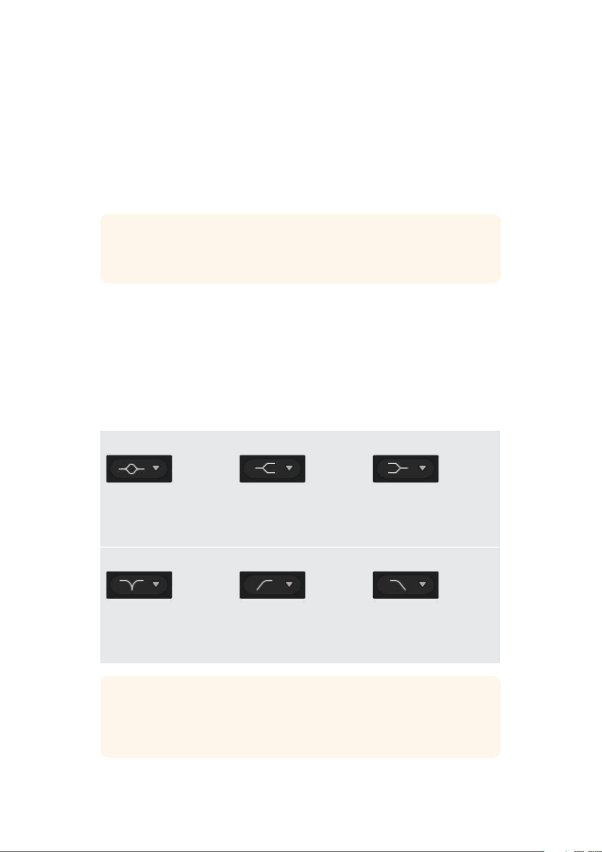
Band Filters
There are six different types of band filters you can choose from. These filters include bell,
high shelf, low shelf, notch, high pass, and low pass. These filters let you control specific
zones within the frequency range. For example, a low shelf filter lets you increase or decrease
the level of volume for lower frequencies on the graph, and a high shelf filter controls the
higher frequencies.
Try setting a low shelf filter to band 3 and make changes to the gain setting. You will see the
changes are weighted towards the low end frequencies on the graph.
A description for each filter type is provided below.
Bell High Shelf Low Shelf
This filter is used to increase
or decrease a range of
frequencies surrounding
adefined frequency.
Lets you increase or decrease
the level of volume for higher
frequencies along the graph.
Lets you increase or decrease
the level of volume for lower
frequencies along the graph.
Notch High Pass Low Pass
This filter lets you remove,
orcut, a defined frequency.
Smoothly removes extreme
low end frequencies, allowing
the high end frequencies to
pass unaffected.
Smoothly removes extreme
high end frequencies, allowing
the low end frequencies to
pass unaffected.
TIP It’s not uncommon to have filters on each band overlapping on the graph curve
with adjustments working together. For example, you may have a low shelf filter
applied to band 4, and a notch filter on band 5 reducing a frequency within the
same range.
28Using ATEM Software Control
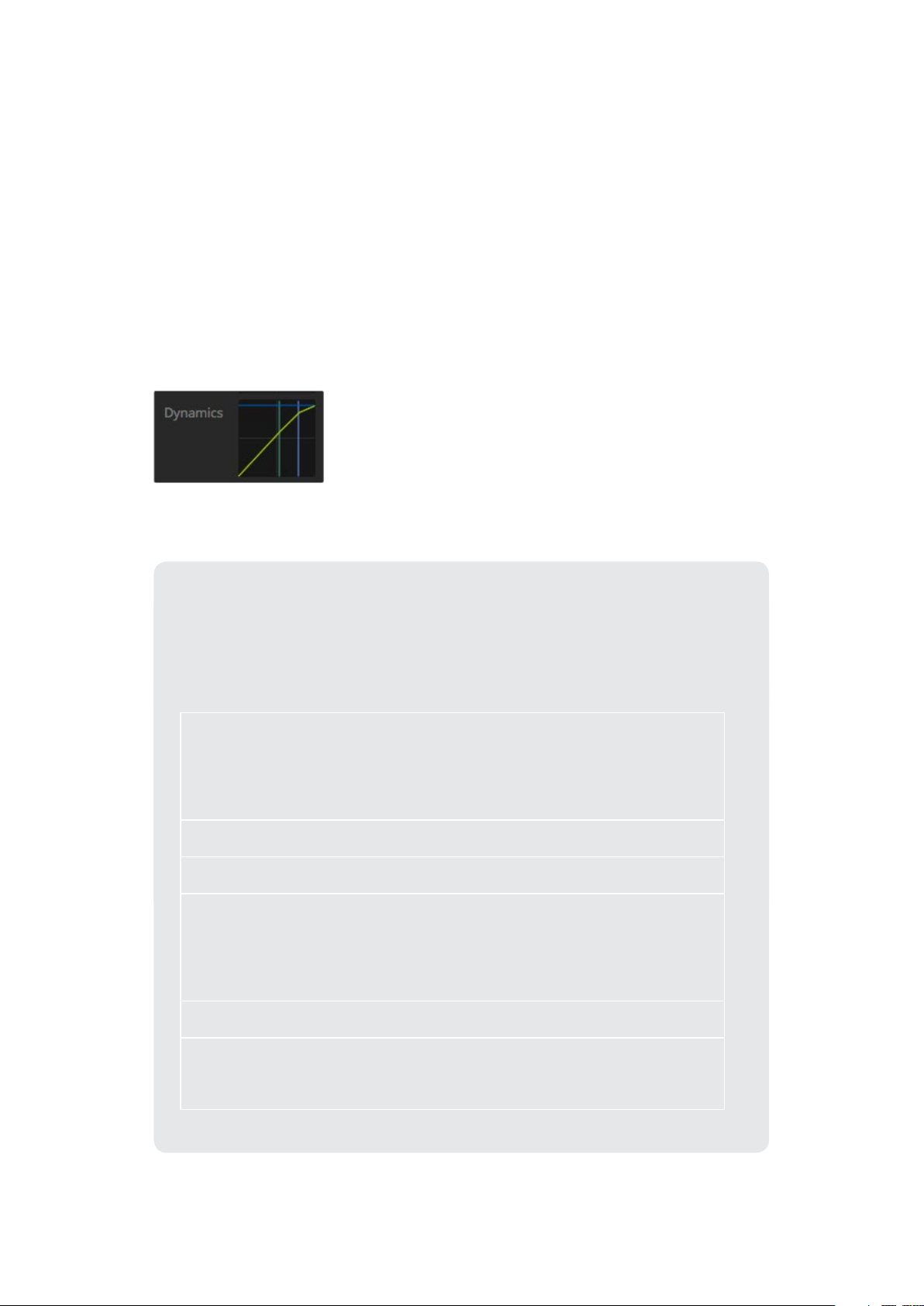
Dynamics Controls
In addition to the 6 band parametric equalizer, you can also enhance and finesse the input
andmaster output audio using dynamics controls. Where the equalizer lets you control the
frequencies within a signal, dynamics controls let you set how various levels behave. Levels
within the signal can be adjusted including expanding the dynamic range between low levels
and high levels, gating an input so you can choose what is stronger or softer within a signal,
oryou can even use the compressor and limiter so that audio can be generally lifted and made
stronger without clipping.
Combined with equalizer controls, these features are extremely powerful, giving you the ability
to precisely shape and define the audio and generally optimize the sound of the master output.
This section describes the expander, gate, compressor and limiter controls.
The dynamics controls can be opened for
each input and the master output by clicking
on its corresponding dynamics indicator
Common Dynamics Settings
The expander/gate, compressor and limiter share common settings that let you shape
how each function affects the audio. For example the level at which the function
initiates, how long the function is applied, the strength of the function, etc. The settings
available differ depending on the dynamics control you are using.
Threshold
Sets the sound level at which the function activates. For example, setting
the threshold for the compressor to -20dB tells your switcher to activate
compression when the signal rises above -20dB. Alternatively, setting the
expander to -40dB means the switcher will only initiate the expander once
the signal level drops below -40dB.
Range
This setting defines the range of decibels affected by the function.
Ratio
Defines the maximum strength of the function once initiated.
Attack
Sets the smoothness of the function when it initiates. For example, a long
attack will allow the function to fade into the signal, blending in better
without drawing too much attention, whereas a short attack may be better
for complex sound activity with many quick variations where a longer
attack may cause artifacts.
Hold
Sustains the dynamics function over an adjustable period of time.
Release
Similar to attack but occurs at the end of the function activit y. For example,
lets the dynamics function ease out gradually, or fall away rapidly, once the
level moves out of the threshold.
29Using ATEM Software Control
Expander/Gate
The first set of dynamics parameters can be switched between expansion and gating.
Expansion emphasizes differences in volume by lowering the level of soft parts of the signal
relative to the level of louder parts. You can use an expander to emphasize the differences
between quiet and loud parts of a track, or to increase the dynamic range of a signal and
minimize unwanted noise.
Gating is like an exaggerated expander, reducing the level or even silencing parts of a signal
that fall below a certain level in order to reduce or eliminate noise in quiet parts of a recording.
For example, a range of 15 to 20 dB can reduce breathing in a vocal track but leaves just
enough to sound natural.
Gating is extremely effective, but it’s also very powerful so requires careful attention. If the gate
threshold is set too high it can cause artifacts, such as cutting off the start of a syllable or the
quiet end of a word. You can compensate by reducing the threshold slightly, or by increasing
the attack or release time.
Compressor
Compression lets you reduce peaks in an audio signal, reducing the dynamic range of a signal,
so you can boost the overall level without clipping. This is helpful when you want to make sure
the loud elements in a signal don’t diminish the strength of quieter sounds, or to smoothen
changes in audio levels within the signal.
TIP It’s a good idea to apply the compressor after you have set the EQ controls.
Make Up
The make up setting lets you increase the overall signal in combination with compression
settings. With loud parts of the audio reduced using compression, you can now use the make
up control to boost the overall sound without clipping.
Limiter
The limiter prevents peaks of the signal from exceeding a set maximum level. A limiter is helpful
to prevent hard clipping. For example, if you set the limiter to -8 dB, the input signal will never
exceed that level. Adjusting the attack, hold and release settings will set how gentle the limiter
affects the signal.
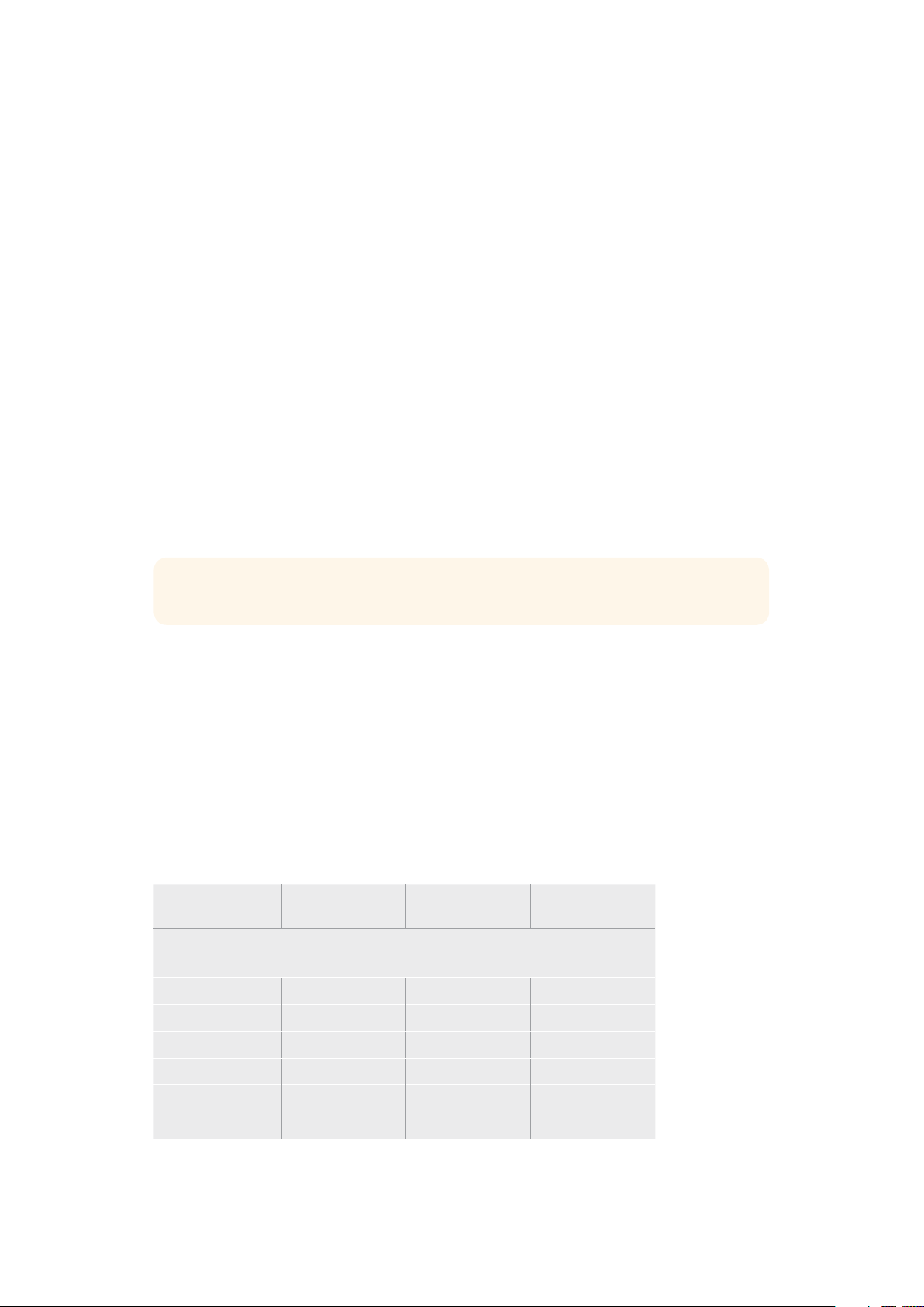
Dynamics Controls Characteristics
Control Minimum Default Maximum
Expander/Gate
Expander Controls*
Threshold -50dB -45dB** 0dB
Range 0dB 18dB 60dB
Ratio 1.0:1 1 .1:1 10:1
Attack 0.5ms 1.4ms 30ms
Hold 0.0ms 0.0ms 4s
Release 50ms 93ms 4s
30Using ATEM Software Control
Loading...