

Biostar PT890 775 SE Owner's Manual

PT 890 775 SE Setup Manual
FCC Inf or m at ion and Copyri ght
This equipment has been tested and found to comply with the limits of a Class
B digital device, purs uant to Part 15 of the FCC Rules. T hese limits are designed
to provide reasonable p rotec tion agai nst harmful i nterference in a residential
installation. This equipment generates , uses and can radiate radio frequency
energy and, if not installed and used in accordance with the instructions , may
cause harmful interference to radio communications. There is no guarantee
that interfe rence will not occur in a particular ins talla tion.
The vendor ma kes no represe ntations o r warran ties with res pec t to th e
contents here and s pecially disclaims any implied warranties of merchantability
o r fi tnes s f o r a ny p u rp os e . F u rt he r t he ve nd o r rese rves the ri g ht to rev ise this
publication and to make changes to the contents here without obligation to
notify any party beforehand.
D uplication of this publication, in pa rt or in whole , is not allowed wi thout first
obtaining the vendor’s approval in writing.
The content of this user’s manual is subject to be changed without notice and
we will not be responsible for any mistakes found in this use r’s manual. All the
brand and product names are trademarks of their respective companies.

Table of Contents
Chapter 1: Introduction .............................................3
1.1 Before You Start...................................................................3
1.2 Package Checklist................................................................3
1.3 Motherboard Features..........................................................4
1.4 Re a r P a nel Co n nec to rs (fo r Ver 6 .x) ....................................... 6
1.5 Rea r Pa nel Co n nec to rs (fo r Ver 5 .x)....................................... 6
1.6 Mo t he r boa r d Layo u t (for Ve r 6.x )..........................................7
1.7 Mo t he r bo ar d Layou t (for Ver 5.x )..........................................8
Chapter 2: Hardware Installation..............................9
2.1 Installing Ce ntral Proce ssing Unit (CPU) ................................ 9
2.2 FAN Heade rs.......................................................................11
2.3 Installing System Me mory.....................................................12
2.4 Con necto rs a nd Slo ts............................................................13
Chapter 3: Headers & Jumpers Setup .....................15
3.1 Ho w to Se tu p J um per s..........................................................15
3.2 Det ail Settin gs.....................................................................15
Chapter 4: RAID Functions.......................................21
4.1 Operation Syste m................................................................21
4.2 Raid Array s.........................................................................21
4.3 How RA I D Wo r k s.................................................................21
Chapter 5: Useful Help .............................................23
5.1 Dri ver Instal latio n Note.......................................................23
5.2 Award BIOS Beep Code ........................................................24
5.3 Extra Informati on ................................................................24
5.4 Troubl eshooting...................................................................26
Chapter 6: WarpSpeeder™ .......................................27
6.1 Introduction........................................................................27
6.2 System Requirement............................................................27
6.3 Installation.........................................................................28
6.4 WarpSpeede r™....................................................................29
Appendencies: SPEC In Other Language ................36
German................................................................................................36
France..................................................................................................38
Italian..................................................................................................40
Spanish................................................................................................42
Portuguese ...........................................................................................44
Polish...................................................................................................46
Russian................................................................................................48
Arabic..................................................................................................50
Japanese..............................................................................................52

PT890 775 SE
CHAPTER 1: INTRODUCTION
1.1 BEFORE YOU START
Tha nk you for choosing ou r produ ct. Be fore you start installing the
mothe rboa rd, plea se make su re you follow the ins tructio ns belo w:
Prepare a dry and stable working environment with
s uffi cie nt lighting .
Always disconnect the computer from power outlet
be fo re ope ra tion .
Befo re you take the m o the rboa rd ou t f rom a n ti -s ta tic
bag, ground yourself properly by touching any safely
grounde d ap pliance, o r use g ro unded wrist strap to
remove the static charge.
Avo id tou ch ing the compone nts o n m o the rboa rd o r the
rea r side of the board unless necessa ry. Hold the bo ard
on the edge , do not try to be nd o r flex the board .
Do not lea ve any un fastene d small pa rts inside the
case after installation. Loose parts will cause short
circuits which may damage the equipment.
Keep the computer from dangerous area, such as heat
source, humid air and wate r.
1.2 PACKAGE CHECKLIST
FDD Cable X 1
HDD Cable X 1
Use r’s Manua l X 1
Fully Setup Driver CD X 1
Rear I/O Panel for ATX Case X 1
Se ria l ATA Ca b le X 1 ( op tiona l)
Se ria l ATA Po we r S witch Cab le X 1 (op tiona l )
USB 2.0 Cable X1 (optional)
S/PDIF Cable X 1 (optional)
3

Motherboard Manual
1.3 MOTHERBOARD FEATURES
Ver 5.x Ver 6.x
LGA 77 5
Intel Core2Duo/ Pentium 4 / Pentium D /
CPU
FS B 400 / 53 3 / 800 / 1066 MHz 400 / 53 3 / 800 / 1066 MHz
Chipset
Super I/O
Main
Memory
IDE
SATA
Celeron D pr ocessor up to 3.8 GHz
Suppor ts Hy per -Threadin g / Exec ute
Disable Bit/ Enh anced Intel S peedStep® /
Intel Exte nded Memory 64 technology
VIA PT890
VIA VT8237A
ITE I T 87 12F
Provides the most commonly used legacy
Super I/O functionality.
Low Pi n C ount Interf ace
Environment Control initiatives,
H/W Monitor
Fan S pee d Co ntroller
ITE' s "Smart Guardia n" fu nct ion
DIMM Slots x 2
Support s D DR2 400 / 533
Eac h DIM M sup port s 256/ 51 2MB /1GB / 2GB
DDR2
Max Memory Capicity 4GB
Single Channel Mode DDR2 memory
module
Registered DIMM and ECC DIMM is not
supported
Integrated IDE Controller
Ultra DMA 33~133 B us Master Mode
supports PI O Mo de 0~ 4,
Integrated Serial ATA Controller
Data transfer rates up to 1.5 Gb/s.
SATA Version 1.0 specification complia nt.
LGA 77 5
Intel Core2Duo/ Pentium 4 / Pentium D /
Celeron D pr ocessor up to 3.8 GHz
Suppor ts Hy per -Threadin g / Exec ute
Disable Bit/ Enh anced Intel S peedStep® /
Intel Exte nded Memory 64 technology
VIA PT890
VIA VT8237A
ITE I T 87 12F
Provides the most commonly used legacy
Super I/O functionality.
Low Pi n C ount Interf ace
Environment Control initiatives,
H/W Monitor
Fan S pee d Co ntroller
ITE' s "Smart Guardia n" fu nct ion
DIMM Slots x 2
Support s D DR2 400 / 533
Eac h DIM M sup port s 256/ 51 2MB /1GB / 2GB
DDR2
Max Memory Capicity 4GB
Single Channel Mode DDR2 memory
module
Registered DIMM and ECC DIMM is not
supported
Integrated IDE Controller
Ultra DMA 33~133 B us Master Mode
supports PI O Mo de 0~ 4,
Integrated Serial ATA Controller
Data transfer rates up to 1.5 Gb/s.
SATA Version 1.0 specification complia nt.
4

PT890 775 SE
Ver 5.x Ver 6.x
Realtek RTL 8201CL
LAN PHY
Sound
Codec
On Board
Connector
Back Panel
I/O
Board S ize 190 mm (W ) x 294 m m (L) 190 mm (W) x 294 mm (L )
Special
Features
OS
Suppor t
10 / 100 Mb/s auto negotiation
Half / Full duplex capability
AL C888
7.1 channels a udio out
High Defi nit ion Audio
PCI Expr ess x 16 slot x1 PCI Expr ess x 16 slot x1
PCI Expr ess x 1 slot x1 PCI Express x 1 slot x1 Slots
PCI s lot x4 PCI s lot x4
Floppy connector x1 Floppy connector x1
IDE C o nnec tor x2 IDE Co nnect or x2
Printer Port C onnector x1 Printer Port C onnector x1
SATA Connector x2 SATA Connector x2
Front Pa nel Co nnect or x1 Front Pa nel Co nnect or x1
Front Audi o Co nnector x1 Front Audi o Connector x1
CD-in Co nnec tor x1 CD-in Co nnect or x1
S/PDIF out connector x1 S/PDIF out connector x1
CPU Fan hea der x1 C PU Fan hea der x1
System Fan hea der x1 S ys tem Fan hea der x1
Clear CMOS header x1 Clear CMOS header x1
USB connector x2 USB connector x2
Power Connector (24pi n) x1 Power Connector (24pin) x1
Power Connector (4pin) x1 Power Connector (4pin) x1
PS/2 Keyb oard x1
PS/2 Mo use x1
Serial Port x1
LAN port x1
USB Port x4
Audio Jack x6
RAID 0 / 1 support RAID 0 / 1 support
Windows 2000 / XP / VISTA
Biostar Reserves the right t o add or rem o ve
support for any OS with or without notice.
Realtek RTL 8201CL
10 / 100 Mb/s auto negotiation
Half / Full duplex capability
AL C861VD
5.1 channels a udio out
High Defi nit ion Audio
PS/2 Keyb oard x1
PS/2 Mo use x1
Serial Port x1
LAN port x1
USB Port x4
Audio Jack x3
Windows 2000 / XP / VISTA
Biostar Reserves the right t o add or rem ove
support for any OS with or without notice.
5
Motherboard Manual
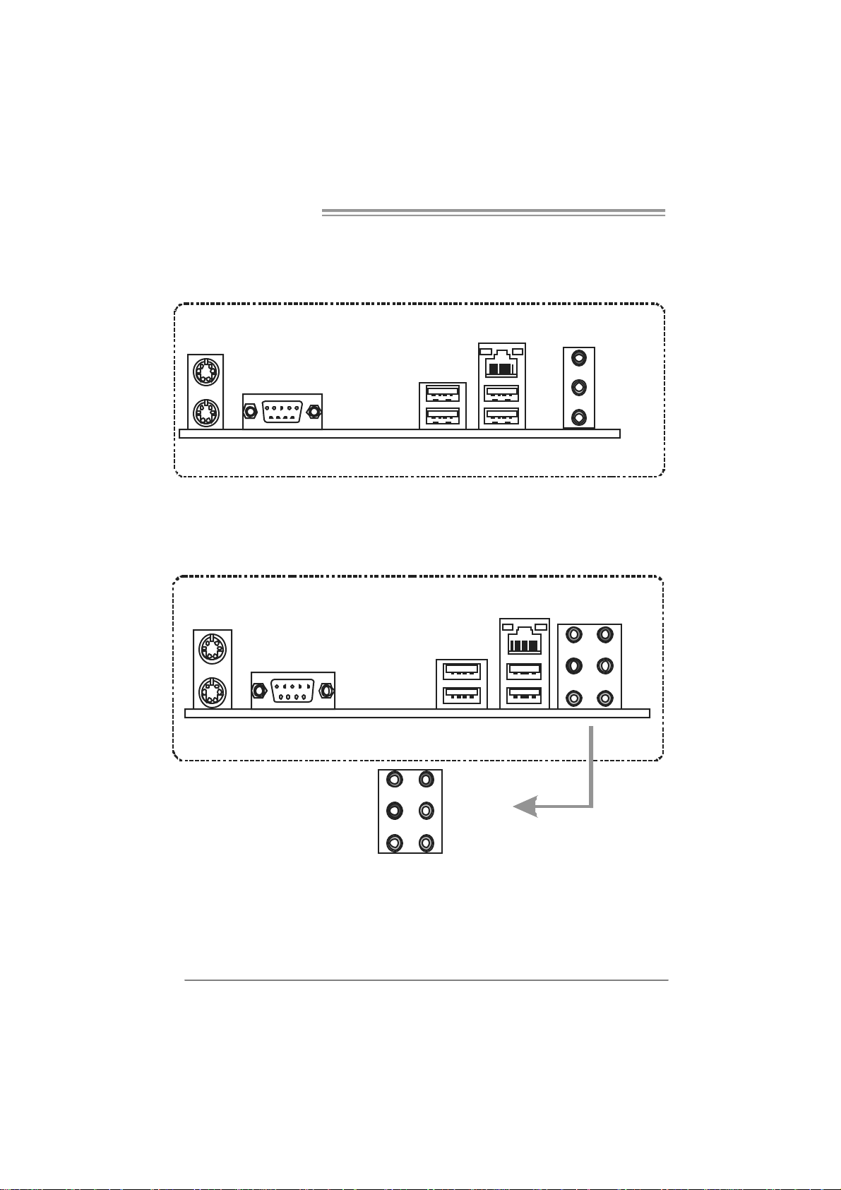
1.4 R
PS /2
Mouse
PS/2
Keyboard
EAR PANEL CONNECTORS (FOR VER 6.X)
LA N
COM1
USBX2USBX2
1.5 REAR PANEL CONNECTORS (FOR VER 5.X)
PS/2
Mou se
LAN
L ine In/
Su rroun d
Lin e Out
Mic In 1 /
Bass/ Ce nter
PS / 2
Keyboard
6
COM1
Center
Rear
Side
Li ne In
Li ne Out
Mic In
USBX2USBX2

PT890 775 SE
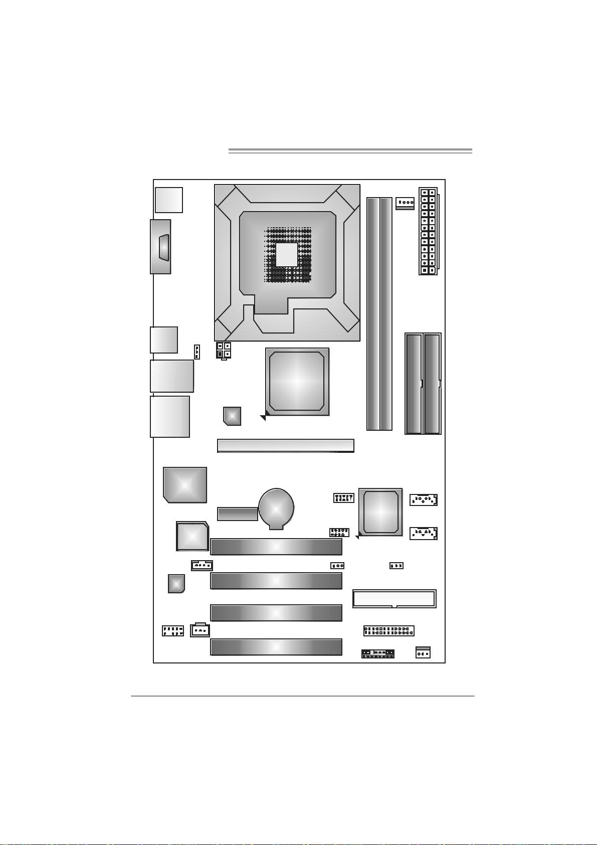
1.6 MOTHERBOARD LAYOUT (FOR VER 6.X)
JKBMS1
C
O
J
M
C
1
O
M
1
JU SB 1
JUSBLAN1
JAUDIO1
Super
I/O
Codec
JAUDIOF1
Note: represents the 1■
JUSBV1
BI OS
JATXP WR2
LA N
PCI-EX1 _1
JCDIN1
J SPD IF_ OUT1
LGA775
CPU 1
VIA
PT890
PC I- EX 16
BAT1
PCI1
PCI2
PCI3
PCI 4
st
pin.
JUSB2
JUS B3
J USBV2
DIMM1
VIA
VT8237A
JCMOS1
JPR NT1
JPANEL 1
DIMM2
FDD1
JCFAN1
J ATXPW R1
IDE 1
JSATA2
JS ATA1
JS F AN1
IDE 2
7
Motherboard Manual
1.7 MOTHERBOARD LAYOUT (FOR VER 5.X)
JKB MS1
C
O
J
M
C
1
O
M
1
JU SB 1
JUSBLAN1
JAUDIO2
Super
I/O
Codec
JAUDIOF1
Note: represents the 1■
JUSBV1
BIO S
JATX P W R2
LA N
PCI-EX1_1
JCDIN1
J SPDIF _O UT1
LGA775
CPU 1
VIA
PT890
PC I- EX 16
BAT1
PCI1
PCI2
PCI3
PCI 4
st
pin.
JUSB2
JUS B3
J USBV2
DIMM1
VIA
VT8237A
JCMOS1
JPR NT1
JPANEL 1
DIMM2
FDD1
JCFAN1
J ATXPW R1
IDE 1
JSATA2
JS ATA1
JS F AN1
IDE 2
8
PT890 775 SE
CHAPTER 2: HARDWARE INS TALLATION
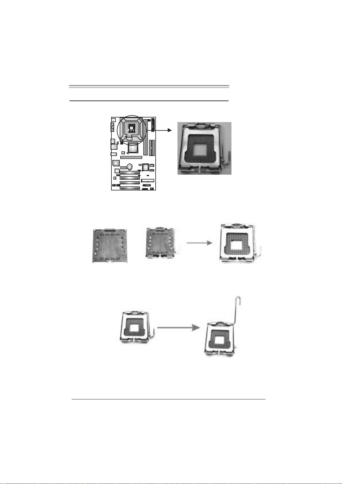
2.1 INSTALLING CENTRAL PROCESSING UNI T (CPU)
Special Notice:
Remo v e Pin Cap before installation, and ma ke goo d preservation
for future use. When the CPU is removed, cov er the Pin Cap on the
empty so cket to ensure pin legs won’ t be damag ed.
Pin Cap
Step 1: Pull the socket locking lever out from the socket and then raise
the lever up to a 90-degree angle.
9
Motherboard Manual
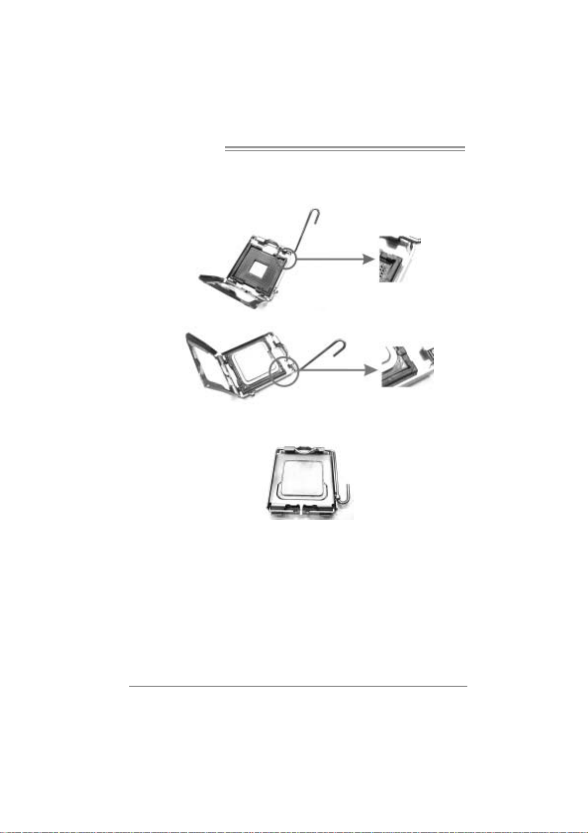
Step 2: Look for the triangular cut edge on socket, and the golden dot on
CPU should point forwards this triangular cut edge. The CPU will
fit only in the correct orientation.
Step 2-1:
Step 2-2:
Step 3: Hold the CPU down firmly, and then lower the lever to locked
position to complete the installation.
Step 4: Put the CPU Fan and heatsink assembly on the CPU and buckle it
on the retention frame. Connect the CPU FAN power cable into
the JCFAN1. T his completes the installation.
10
PT890 775 SE
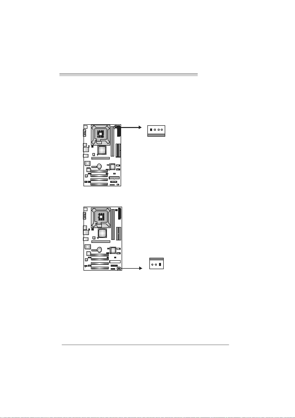
2.2 FAN HEADERS
These fan headers support cooling-fans built in the computer. The fan
cable and connector may be different according to the fan manufacturer.
Connect the fan cable to the connector while matching the black wire to
pin#1.
JCFAN1: CPU Fa n Header
Pin
14
JCFAN1
JSF AN1 : Syst em F an H ead er
JSFAN1
Assignment
1 Ground
2 +12V
3 FAN RPM rate
sense
4 Smart Fan
Control
Pin
Assignment
1 Ground
2 +12V
3 FAN RPM rate
sense
13
Note:
The J CFAN 1 a nd JSF AN 1 s uppor t 4-pin and 3-pi n h ead connec tor s. When c on necti ng
with wir es ont o c onnec t or s, ple ase note tha t t he re d wire i s t he posi ti ve an d shoul d be
conn ecte d t o pi n# 2, and th e bl ac k wir e is Gro und a nd s ho uld b e c on nect ed to Gr oun d.
11
Motherboard Manual
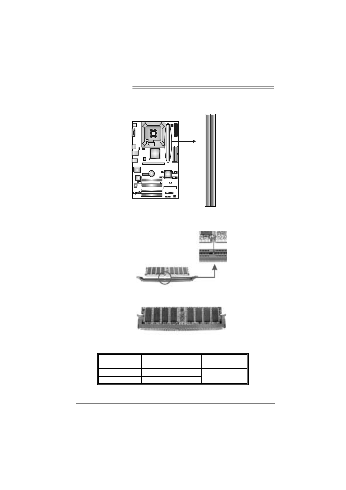
2.3 INSTALLING SYSTEM MEMORY
A. Me mo ry Modu le s
DIMM2
DIMM1
1. Unlock a DIMM slot by pressing the retaining clips outward. Align a
DIMM on the slot such that the notch on the DIMM matches the
break on the Slot.
2. Insert the DIMM vertically and firmly into the slot until the retaining
chip snap back in place and the DIMM is properly seated.
B. Memory Capacity
DI MM Socket
Location
DIMM1 256MB/512MB/1GB/2GB
DIMM2 256MB/512MB/1GB/2GB
DDR Module
To t al M e m o r y
Size
Max is 4GB.
12
PT890 775 SE
2.4 CONNECTORS AND SLOTS
FDD1: Floppy Disk Connecto r
The motherboard prov ides a standard floppy disk connector that supports 360K,
720K, 1.2M, 1.44M and 2.88M floppy disk ty pes. This connector supports the
prov ided f loppy drive ribbon cables.
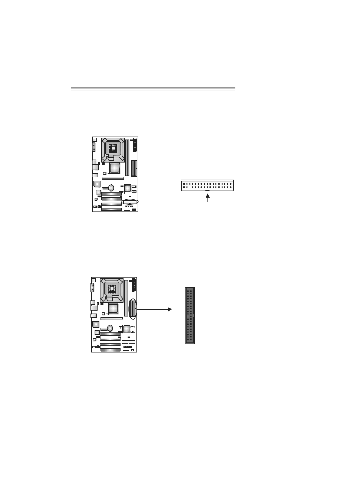
IDE1 / IDE2: H ard Disk Connectors
The motherboard has a 32-bit Enhanced PCI IDE Controller that prov ides PIO
Mode 0~4, Bus Master, and Ultra DMA 33/66/100/133 f unctionality . It has two
HDD connectors IDE1 (primary) and IDE2 (secondary).
The IDE connectors can connect a master and a slave drive, so you can
connect up to four hard disk drives. The f irst hard drive should always be
connected to IDE1.
2
1
3940
21
34
33
IDE2IDE1
13
Motherboard Manual
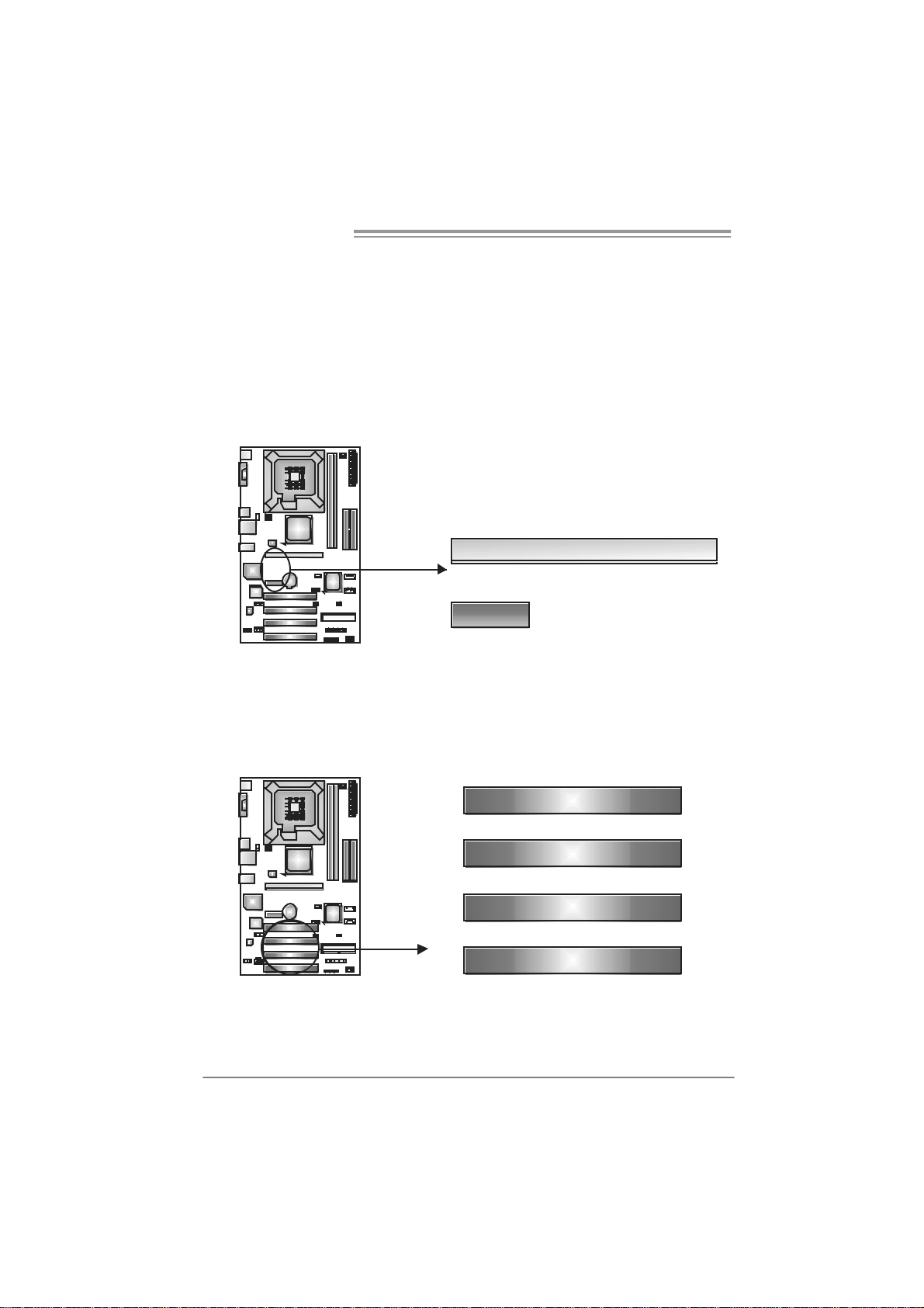
PCI-EX16: P CI-Exp re s s x1 6 Slot
- PCI-Express 1.0a compliant.
- Maximum theoretical realized bandwidth of 4GB/s simultaneously per
direction, f or an aggregate of 8GB/s totally.
PCI-EX1_1: PCI-Express x1 s lots
- PCI-Express 1.0a compliant.
- Data transf er bandwidth up t o 250MB/s per direction; 500MB/s in total.
- PCI-Express supports a raw bit-rate of 2.5Gb/s on the data pins.
- 2X bandwidth ov er the t raditional PCI arc hitecture.
PCI-EX16
PCI-EX1_1
PCI1~ PCI4: Peripheral Com ponent Interconne ct Sl ots
This motherboard is equipped with 4 standard PCI slots. PCI stands f or
Peripheral Component Interconnect, and it is a bus standard for expansion
cards. This PCI slot is designated as 32 bits.
14
PCI1
PCI2
PCI3
PCI4
PT890 775 SE
CHAPTER 3: HEADERS & JUMPERS SETUP
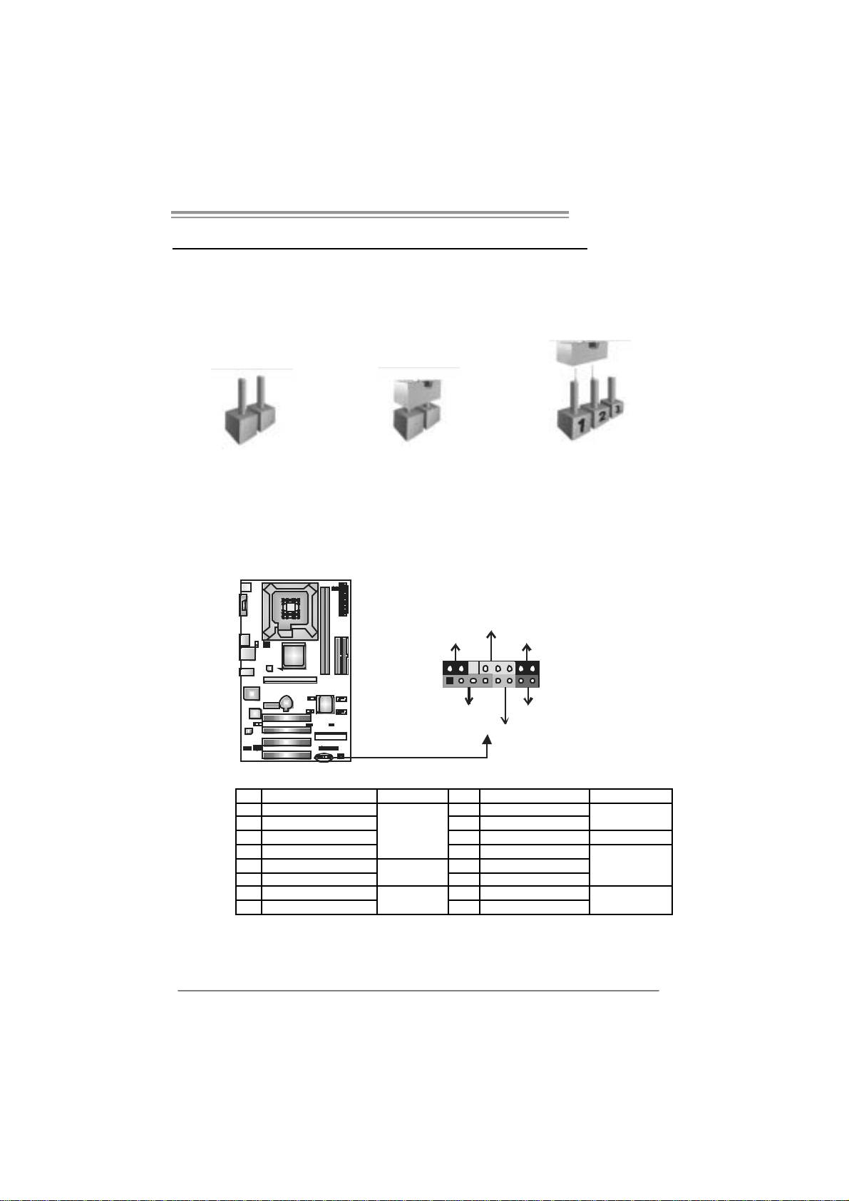
3.1 HOW TO SETUP JUMPERS
The illustration shows how to set up jumpers. When the jumper cap is
placed on pins, the jumper is “close”, if not, that means the jumper is
“open”.
Pin opened Pin closed Pin1-2 closed
3.2 DETAIL SETT INGS
JPANEL1: Front Panel Header
This 16-pin connector includes Power-on, Reset, HDD LED, Power LED, Sleep
button and speaker connection. It allows user to connect the PC case’s f ront
panel switch functions.
PWR_LED
SLP
9
1
SPK
++
HLED
+
On/Off
-
-
RST
16
8
Pin Assignment Functio n Pin Assignment Functio n
1 +5V 9 Sleep control
2 N/A 10 Ground
3 N/A 11 N/A N/A
4 Speaker
5 HDD LED (+) 13 Power LE D (+)
6 HDD LED (-)
7 Ground 15 Power button
8 Reset control
Speaker
Connector
Hard drive
LED
Reset button
12 P ower L ED (+)
14 P ower L ED (-)
16 Ground
Sleep button
Power LED
Power-on button
15
Motherboard Manual
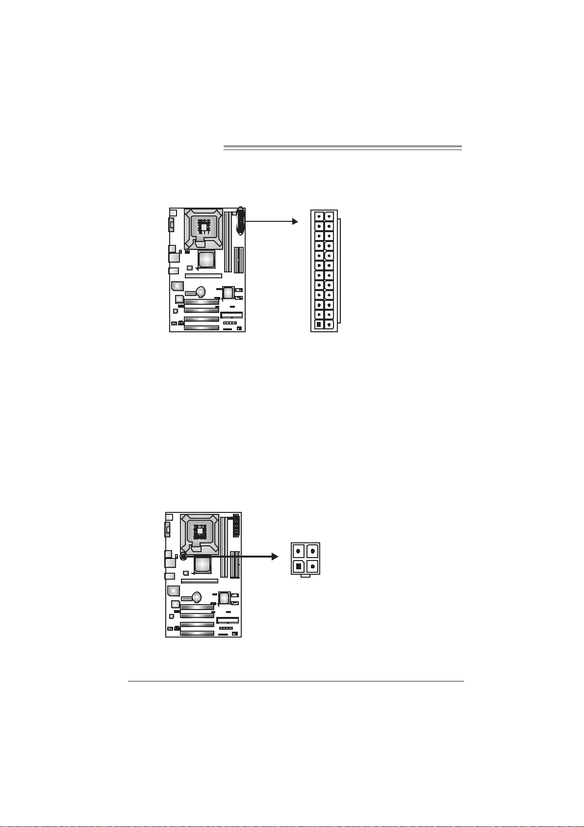
ATX Power Source Connector: JAT XPWR1
JATXPWR1 allows user to connect 24-pin power connector on the ATX power
supply.
12
1
Pin Assignment Pin Assignment
24
13
13 +3.3V 1 + 3.3V
14 -12V 2 +3.3V
15 Gr oun d 3 Gr oun d
16 PS_ON 4 +5V
17 Gr oun d 5 Gr oun d
18 Gr oun d 6 +5V
19 Gr oun d 7 Gr oun d
20 NC 8 PW_ OK
21 +5V 9 Standby Vol t ag e+ 5V
22 +5V 10 +12V
23 +5V 11 +12V
24 Gr oun d 12 +3.3V
JAT XPWR2: ATX Powe r So u rce C onn e ctor
By connecting this connector, it will provide +12V to CPU power c ircuit.
34
12
Pin
Assignment
1 +12V
2 +12V
3 Ground
4 Ground
16
PT890 775 SE
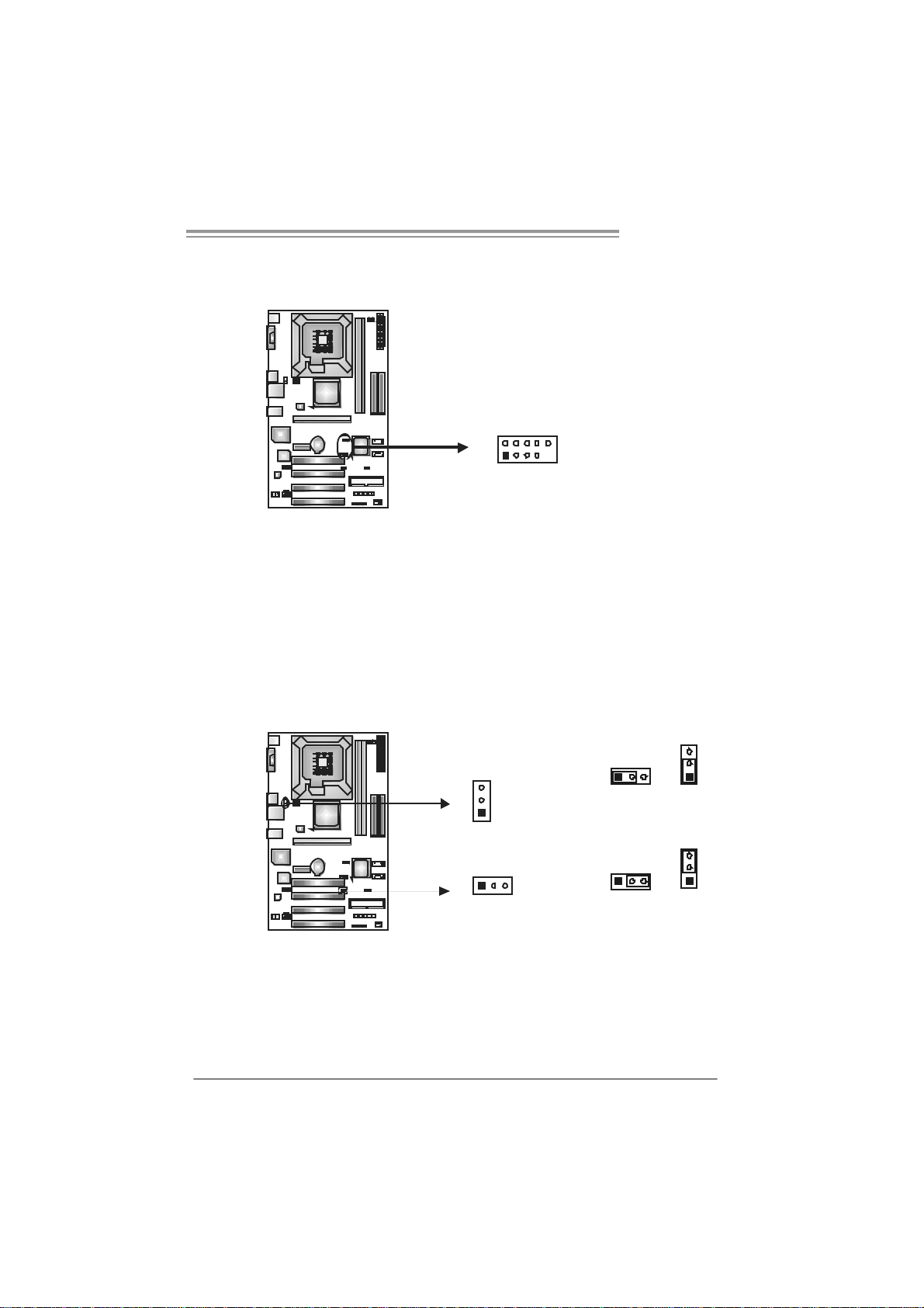
JUSB2/JUSB3: Headers for USB 2.0 Ports at Front Panel
This header allows user to connect additional USB cable on the PC f ront panel,
and also can be connected with internal USB devices, like USB card reader.
Assignment
Pin
1 +5V (fused)
2 +5V (fused)
3 USB4 USB5 USB+
6 USB+
10
9
JUSB2
JUSB3
2
1
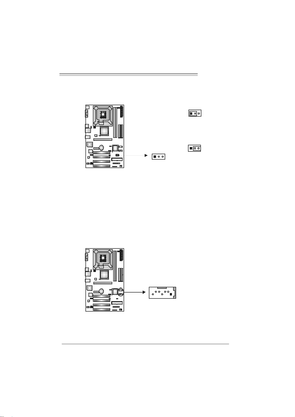
JUSBV1/JUSBV2: Power Sou rc e Headers for USB Ports
Pin 1-2 Close:
JUSBV1: +5V for USB ports at JUSBLAN1/JUSB1.
JUSBV2: +5V for USB ports at front panel (JUSB2/JUSB3).
Pin 2-3 Close:
JUSBV1: USB ports at JUSBLAN1/JUSB1 are powered by +5V standby
JUSBV2: USB ports at front panel (JUSB2/JUSB3) are powered by +5V
v oltage.
standby v oltage.
7 Ground
8 Ground
9 Key
10 NC
3
31
1
3
1
Pin 1-2 close
JUSBV1
13
JUSBV2
1
Pin 2-3 close
3
3
1
Note:
In ord er to s upport this f unction “P ower -On s ystem vi a USB devic e,” “JUSBV1/ JUSBV2”
jumper cap sh ould be plac ed on Pin 2-3 i n di viduall y.
17
Motherboard Manual
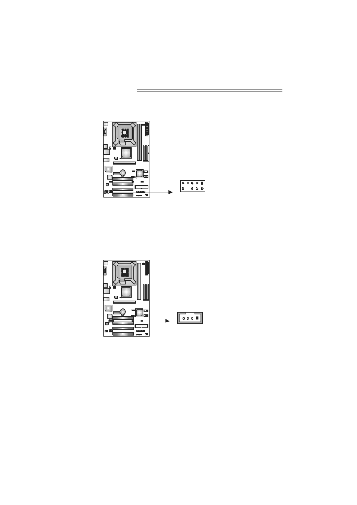
JAUDIOF1: Front Panel Audio Header
This header allows user to connect the front audio output cable with the PC f ront
panel. It will disable the output on back panel audio connectors.
JCDIN1: CD-R OM A ud io-in Connector
This connector allows user to connect the audio source f rom the variaty devices,
like CD-ROM, DVD-ROM, PCI sound card, PCI TV turner card etc.
Pin Assignment
1 Mi c Left in
2 Ground
3 Mi c Right in
4 GPIO
5 Right line in
6 Jack Sense
7 Front Sense
9
1
210
8 Key
9 Left line in
10 Jack Sense
Assignment
Pin
1 Left Channel Input
2 Ground
3 Ground
4 Right Channel Input
18
14
PT890 775 SE
JCMOS1 : C lea r CMO S Hea der
By placing the jumper on pin2-3, it allows user to restore the BIOS saf e setting
and the CMOS data, please carefully f ollow the procedures to avoid damaging
the motherboard.
13
Pin 1-2 Close:
Normal Operation (default).
13
Pin 2-3 Close:
Clear CMOS data.
※ Clear CMOS Procedures:
1. Remove AC power line.
2. Set the jumper to “Pin 2-3 close”.
3. Wait f or f ive seconds.
4. Set the jumper to “Pin 1-2 close”.
5. Power on the AC.
6. Reset y our des ired password or c lear t he C MOS data.
13
JSATA1 /JS ATA2: Se rial ATA Connect ors
The motherboard has a PCI to SATA Controller with 2 channels SATA interf ace,
it satisfies the SATA 1.0 spec and with transfer rate of 1.5Gb/s.
Pin
Assignment
1 Ground
2 TX +
3 TX -
147
JSATA2
J SATA 1
4 Ground
5 RX6 RX+
7 Ground
19
Motherboard Manual
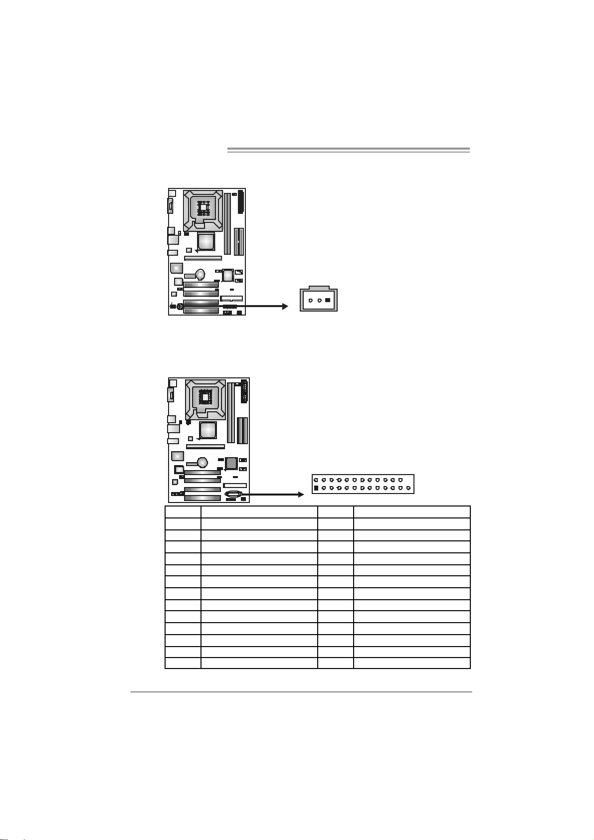
JSPD I F_O UT1: Digital Audio-out Conn ecto r
This connector allows user to connect the PCI bracket SPDIF output header.
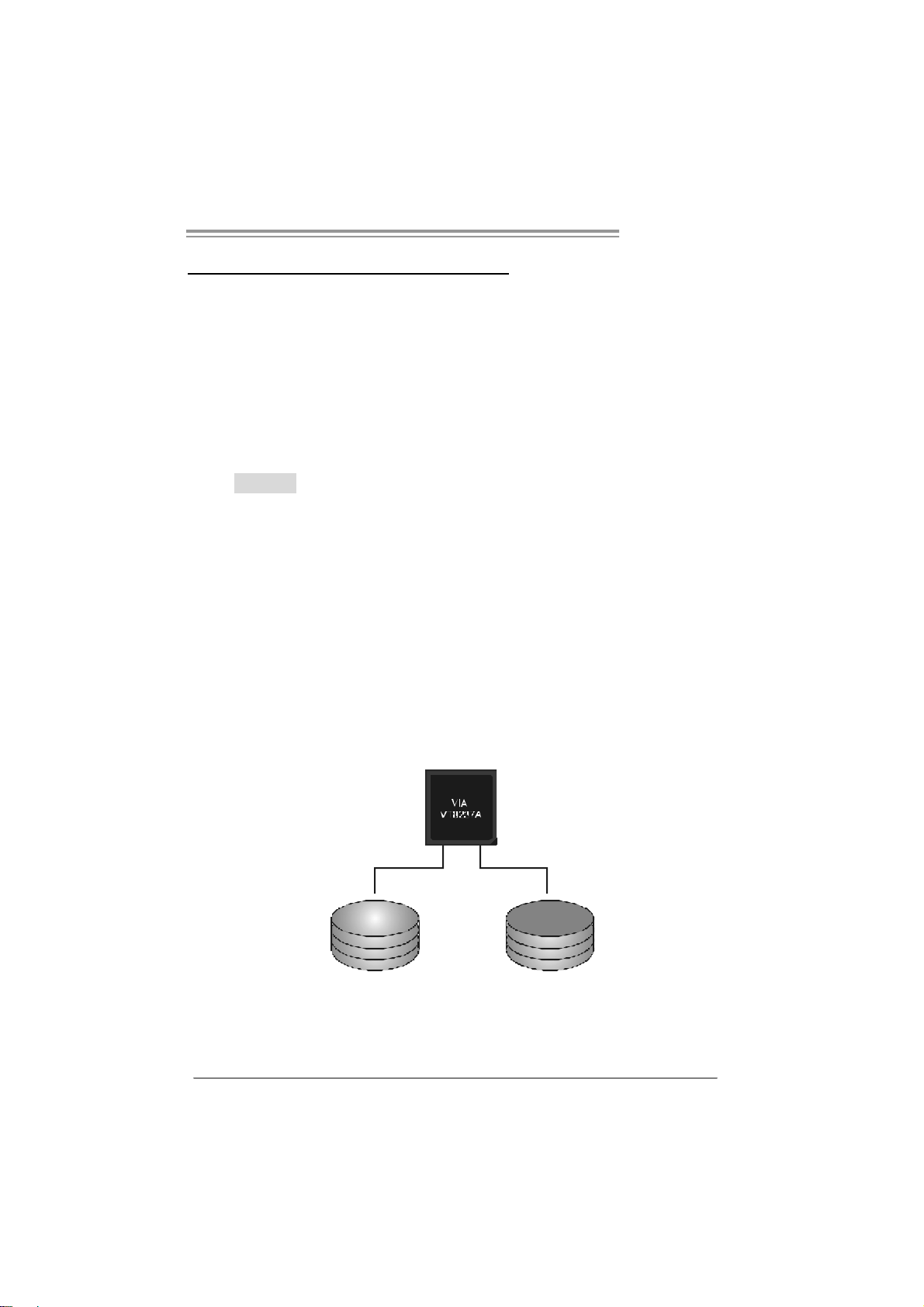
JPRNT1: Printer Port Connector
This header allows you to connect printer on the PC.
Pin
Assignment
1 +5V
2 SPDIF_OUT
3 Ground
13
20
2
1
25
Pin Assignment Pin Assignment
1 -Strobe 14 Gr oun d
2 -ALF 15 Data 6
3 Data 0 16 Gr oun d
4 -Error 17 Data 7
5 Data 1 18 Gr oun d
6 -Init 19 - AC K
7 Data 2 20 Gr oun d
8 -Scl tin 21 Bus y
9 Data 3 22 Gr oun d
10 Gr oun d 23 PE
11 Data 4 24 Groun d
12 Gr oun d 25 SCLT
13 Data 5 26 Ke y
PT890 775 SE
CHAPTER 4: RAID FUNCTIONS
4.1 OPERATION SYSTEM
z Supports Windows XP Home/Prof es sional Edition, and Windows 2000 Prof es sional.
4.2 RAID ARRAYS
RAID supports the following types of RAID arrays:
RAID 0: RAID 0 defines a disk striping scheme that improves disk read and write times for
many applications.
RAID 1: RAID 1 defines techniques for mirroring data.
4.3 HOW RAID WORKS
RAID 0:
The controller “ stripes” data across multiple drives in a RAID 0 array system. It b reaks
up a large file into smaller blocks and performs disk reads and writes across multiple
drives in parallel. The size of each b lock is determined by the stripe size parameter,
which you set during the creation of the RAID set based on the system environment. This
technique reduces overall disk access time and offers high bandwidth.
Fea tures and Be nefits
Drives: Minimum 1, and maximum is up to 6 or 8. Depending on the
platform.
Uses: Intended for non-critical data requiring high data throughput , or any
env ironment that does not require fault tolerance.
Benefits: prov ides inc reased data throughput, es pecially f or large f iles. N o
capacity loss penalty f or parity.
Drawbacks: Does not deliver any fault tolerance. If any drive in the array
f ails, all data is lost.
Fa ult Tolerance : No.
Blo c k 1
Block 3
Block 5
Block 2
Bl ock 4
Bl ock 6
21
Motherboard Manual
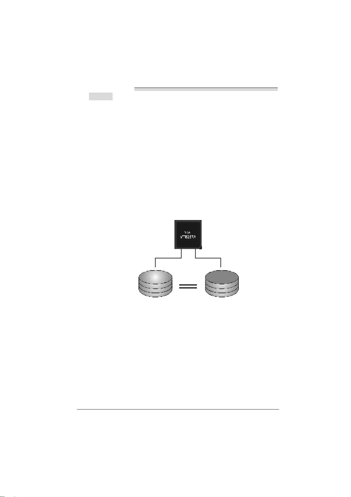
RAID 1:
Every read and write is actually carried out in parallel acro ss 2 disk drives in a RAID 1
array system. The mirrored (backup) copy of the data can reside on the same disk or on
a second redundant drive in the array. RAID 1 provides a hot-standby copy of data if
the active volume or drive is corrupted or becomes unavailable because of a hardware
failure.
RAID techniques can be applied for high-availability solutions, or as a form of
automatic backup that eliminates tedious manual backups to more expensive and less
reliable media.
Fea tures and Be nefits
Drives: Minimum 2, and maximum is 2.
Uses: RAID 1 is ideal for small databases or any other application that
requires f ault tolerance and minimal capacity.
Benefits: Prov ides 100% data redundancy. Should one drive fail, the
controller switches to the other drive.
Drawbacks: Requires 2 drives for the storage space of one driv e.
Perf ormance is impaired during drive rebuilds.
Fault Tolerance : Yes.
22
Blo c k 1
Block 2
Block 3
Block 1
Block 2
Block 3
CHAPTER 5: USEFUL HELP
5.1 DRIVER INSTALL ATION NOTE
After you installed your operating system, please insert the Fully Setup
Driver CD into your optical drive and install the driver for better system
performance.
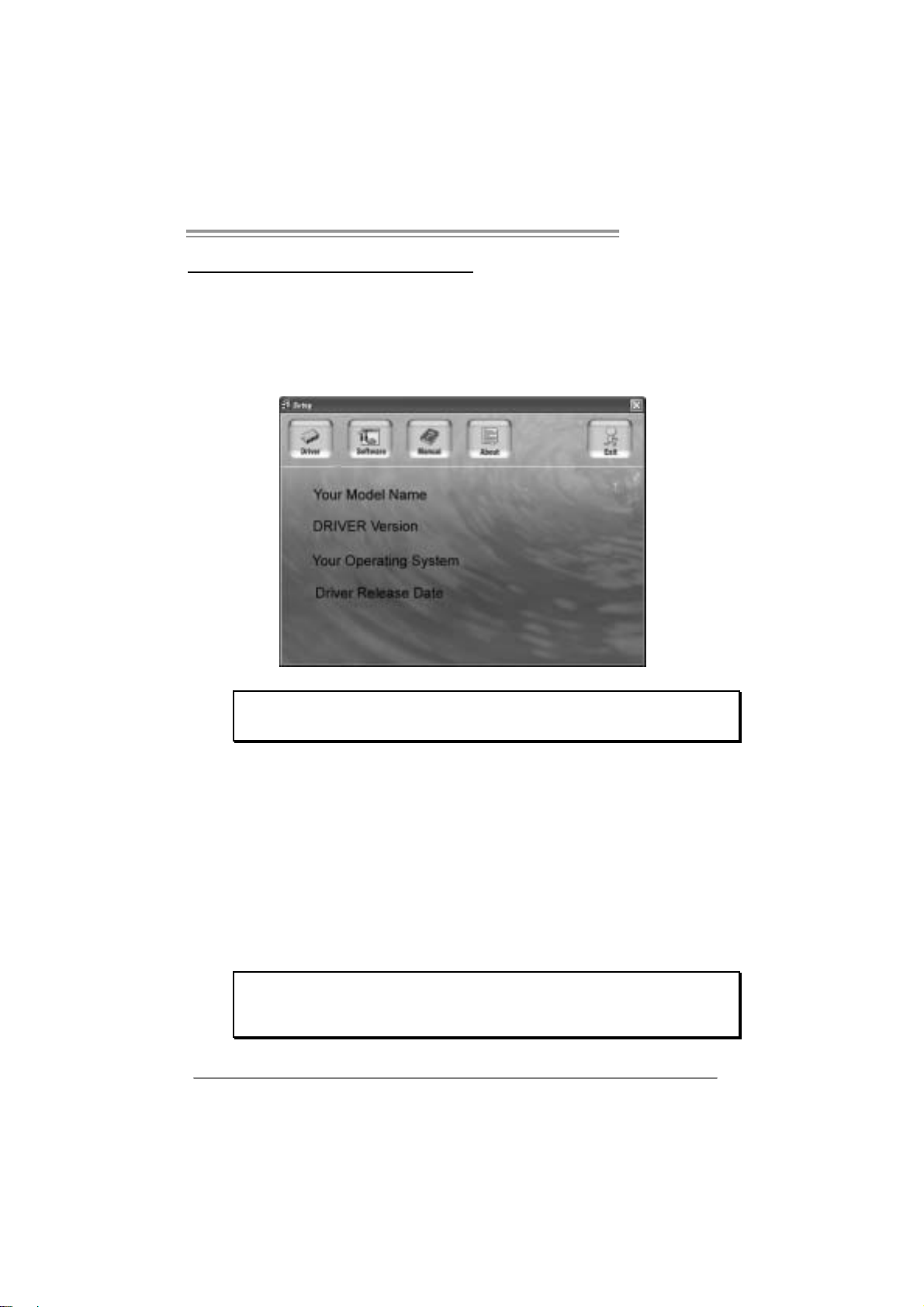
You will see the following window after you insert the CD
PT890 775 SE
The setup guide will auto detect your motherboard and operating system.
Note:
If this win do w didn’ t show up aft er you ins ert th e D river C D , please use file br o ws er to
locate and e xecu te the fi le SETU P.E XE un der your optic al dr i ve.
A. Driver Insta llatio n
To install the driver, please click on the Driver icon. The setup guide will
list the compatible driver for your motherboard and operating system.
Click on each device driver to launch the installation program.
B. Software Installatio n
To install the software, please click on the Software icon. The setup guide
will list the software available for your system, click on each software title
to launch the installation program.
C. Manual
Aside from the paperback manual, we also provide manual in the Driver
CD. Click on the Manual icon to browse for available manual.
Note:
You will need Acrobat R eader to ope n the manual file. Please download the latest version
of Acrob at Re ader software fr om
http://www.adobe.com/products/acrobat/readstep2.html
23
Motherboard Manual
5.2 AWARD BIOS BEEP CODE
Beep Sound Meanin g
One long beep followed by two short
beeps
High-low siren sound CPU ov erheated
One Short beep when system boot-up No error found during POST
Long beeps every other second No DRAM detected or ins tall
Video card not found or video card
memory bad
System will shut down automatically
5.3 EXT RA INFORMATION
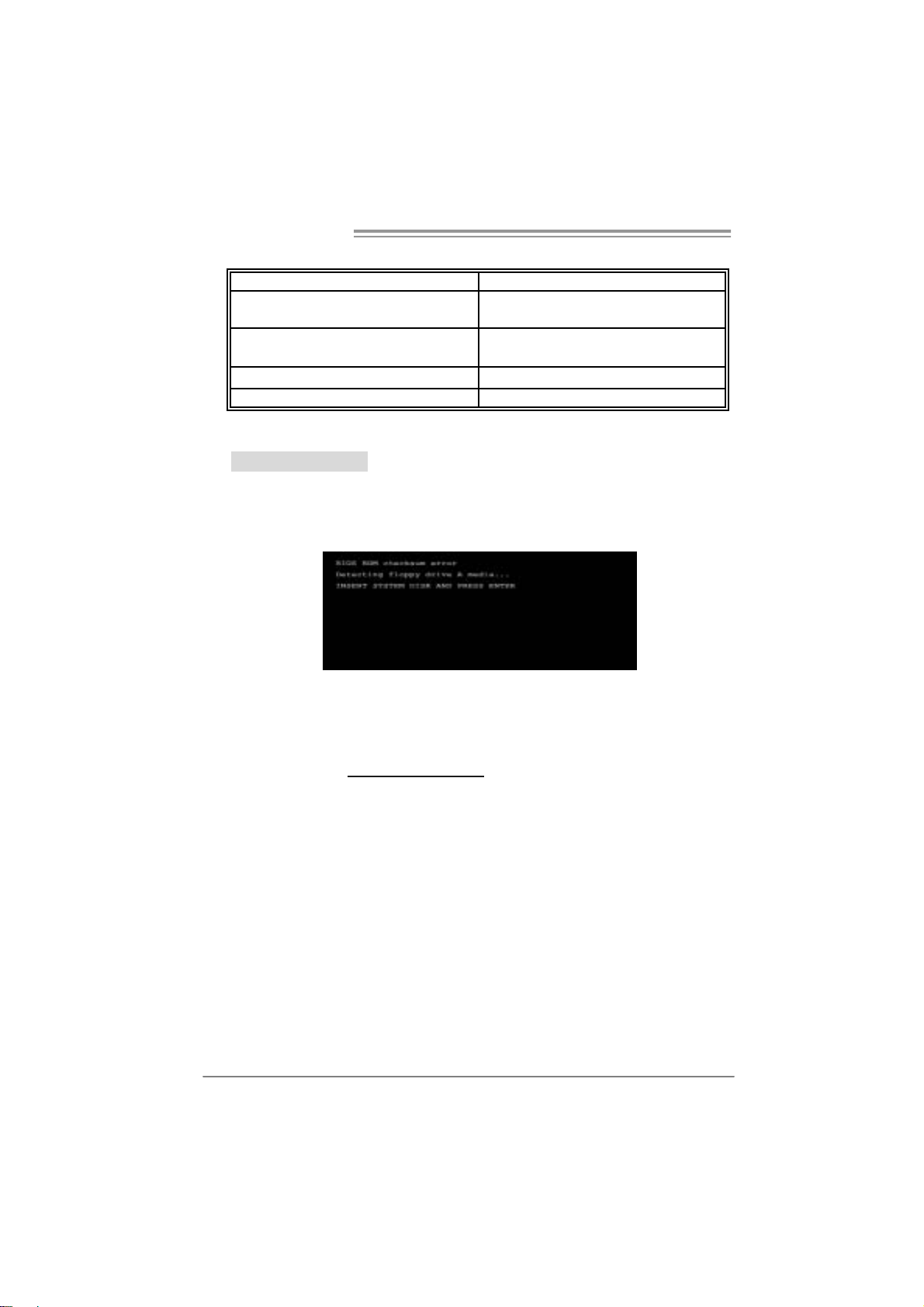
A. BIOS Update
After you fail to update BIOS or BIOS is invaded by virus, the
Boot-Block function will help to restore BIOS. If the following message
is shown after boot-up the system, it means the BIOS contents are
corrupted.
In this Case, please follow the procedure below to restore the BIOS:
1. Make a bootable floppy disk.
2. Download the Flash Utility “AWDFLASH.exe” from the Biostar
website: www.biostar.com.tw
3. Confirm motherboard model and download the respectively BIOS
from Biostar website.
4. Copy “AWDFLASH.exe” and respectively BIOS into floppy disk.
5. Insert the bootable disk into floppy drive and press Enter.
6. System will boot-up to DOS prompt.
7. Type
“Awd flash xxxx.bf/ sn/py/ r” in DOS prompt.
xxxx means BIOS name.)
(
8. System will update BIOS automatically and restart.
9. The BIOS has been recovered and will work properly.
24

PT890 775 SE
B. CPU Overheated
If the system shutdown automatically after power on system for
seconds, that means the CPU protection function has been activated.
When the CPU is over heated, the motherboard will shutdown
automatically to avoid a damage of the CPU, and the system may not
power on again.
In this case, please double check:
1. The CPU cooler surface is placed evenly with the CPU surface.
2. CPU fan is rotated normally.
3. CPU fan speed is fulfilling with the CPU speed.
After confirmed, please follow steps below to relief the CPU protection
function.
1. Remove the power cord from power supply for seconds.
2 . Wa i t f o r se co nd s.
3. Plug in the power cord and boot up the system.
Or you can:
1. Clear the CMOS data.
(See “Close CMOS Header: JCMOS1” section)
2 . Wa i t f o r se co nd s.
3. Powe r on th e system agai n.
25

Motherboard Manual
e
5.4 TROUBLESHOOTING
Probable Solution
1. No power to the system at all
Power light don’t illuminate, f an
inside power supply does not turn
on.
2. Indicator light on key board does
not turn on.
System inoperativ e. Keyboard lights
are on, power indicator lights are lit,
and hard driv e is spinning.
System does not boot from hard disk
driv e, can be booted from optical driv e.
System only boots f rom optical driv e.
Hard disk can be read and applications
can be used but booting from hard disk
is impossible.
Screen message says “Invalid
Configuration” or “CMOS Failure.”
Cannot boot system after installing
second hard drive.
1. Make sure power cable is
securely plugged in.
2. Replace cable.
3. Cont act tec hnic al support.
Using even pressure on both ends of
the DIMM, press down firmly until the
module snaps into place.
1. Check cable running from disk to
disk controller board. Make sure
both ends are securely plugged
in; c h ec k t h e d r iv e ty p e i n t h e
standard CMOS setup.
2. Backing up the hard drive is
extremely important. All hard
disks are capable of breaking
down at any time.
1. Back up data and applications
files.
2. Ref ormat t he hard drive.
Re-install applications and data
using backup disks.
Review system’s equipment. Make sur
correct inf ormation is in setup.
1. Set master/slave jumpers
correctly.
2. Run SETUP program and select
correct driv e types. Call the drive
manufacturers for compatibility
with other drives.
26

PT890 775 SE
CHAPTER 6: WARPSPEEDER™
6.1 INTRODUCTION
[WarpSpeeder™], a new powerful control utility, features three
user-friendly functions including Overclock Manager, Overvoltage
Manager, and Hardware Monitor.
With the Overclock Manager, users can easily adjust the frequency they
prefer or they can get the best CPU performance with just one click. The
Overvoltage Manager, on the other hand, helps to power up CPU core
voltage and Memory voltage. The cool Hardware Monitor smartly indicates
the temperatures, voltage and CPU fan speed as well as the chipset
information. Also, in the About panel, you can get detail descriptions about
BIOS model and chipsets. In addition, the frequency status of CPU,
memory, AGP and PCI along with the CPU speed are synchronically
shown on our main panel.
Moreover, to protect users' computer systems if the setting is not
appropriate when testing and results in system fail or hang,
[WarpSpeeder™] technology assures the system stability by automatically
rebooting the computer and then restart to a speed that is either the
original system speed or a suitable one.
6.2 SYSTEM REQUIREMENT
OS Support: Windows 98 SE, Windows Me, Windows 2000, Windows XP
DirectX: DirectX 8.1 or above. (The Windows XP operating system
includes DirectX 8.1. If you use Windows XP, you do not need to install
DirectX 8.1.)
27
Motherboard Manual
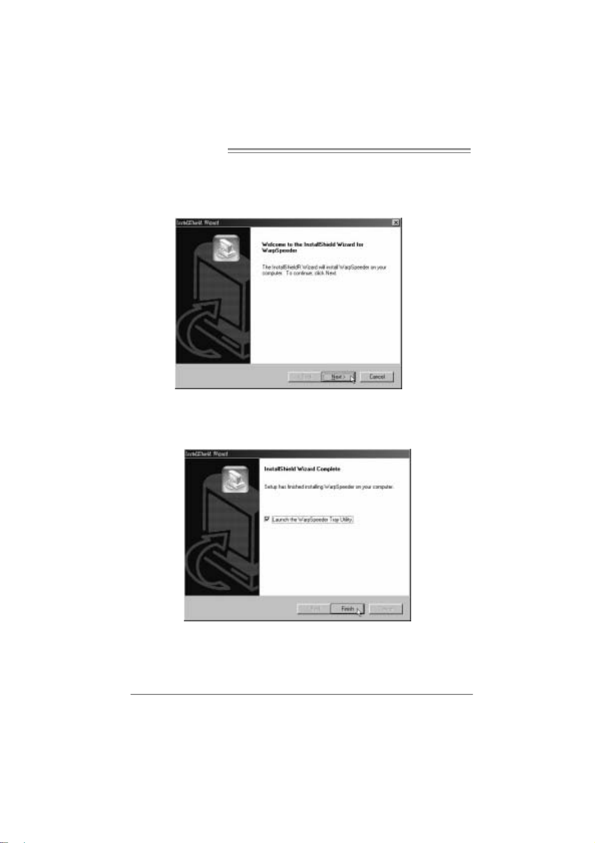
6.3 INSTALLATION
1. Execute the setup execution file, and then the following dialog will pop
up. Please click “Next” button and follow the default procedure to
install.
2. When you see the following dialog in setup procedure, it means setup
is completed. If the “Launch the WarpSpeeder Tray Utility” checkbox
is checked, the Tray Icon utility and [WarpSpeeder™] utility will be
automatically and immediately launched after you click “Finish”
button.
28
Usage:
The following figures are just only for reference, the screen printed in
this user manual will change according to your motherboard on hand.
6.4 WARPSPEEDER™
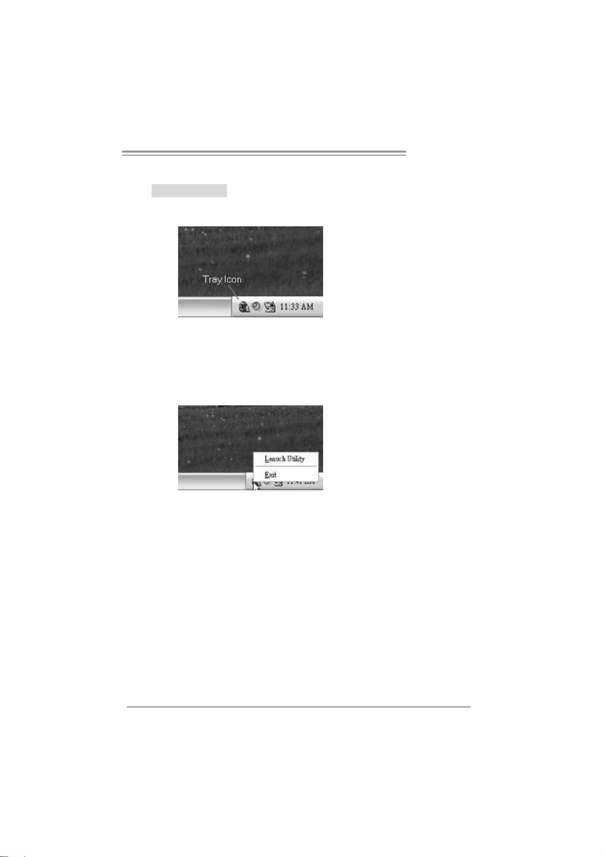
1. Tray Icon:
Whenever the Tray Icon utility is launched, it will display a little tray
icon on the right side of Windows Taskbar.
This utility is responsible for conveniently invoking [WarpSpeeder™]
Utility. You can use the mouse by clicking the left button in order to
invoke [WarpSpeeder™] directly from the little tray icon or you can
right-click the little tray icon to pop up a popup menu as following
figure. The “Launch Utility” item in the popup menu has the same
function as mouse left-click on tray icon and “Exit” item will close
Tray Icon utility if selected.
PT890 775 SE
29
 Loading...