

Page 1

P965 775 Set up Manual
FCC Inf or m at ion and Copyright
This equipment has been tested and found to comply with the limits of a Class
B digital device, pursuant to Part 15 of the FCC Rules. These limits are designed
to prov ide reasonable pro tec tion against harmful interference in a residential
installation. This equipment generates, uses and can radiate radio frequency
energy and, if not installed and used in accordance with the instructions, may
cause harmful interference to radio communications . There is no guarantee
that interference will not occur in a particu la r ins ta lla ti o n .
The vendor makes no re p res e n ta tions or wa r ra nties with r es pec t to th e
contents here and specially disclaims any implied warranties of merchantability
o r fi tn ess fo r a ny p u rp ose . F u rt he r t he ve nd o r res e rves the ri g ht to r ev ise t his
publication and to make changes to the contents here without obligation to
notify any party beforehand.
D uplication of t his publication, in pa rt or in whole, is not allo wed wi thout first
obtaining the vendor’s approval in writing.
The content of this user’s manual is subject to be changed without notice and
we will not be res ponsible for any mistakes found in this user’s manual. All the
brand and product names are trademarks of their respective companies.
Page 2

Table of Content s
Chapter 1: Introduction .............................................1
1.1 Before You Start................................................................... 1
1.2 Package Checklist................................................................ 1
1.3 Motherboard Features..........................................................2
1.4 Rea r Pa nel Co n necto rs (for Ve r 5 .x).......................................4
1.5 Rea r Pa nel Connectors (for Ver 6.x) ....................................... 4
1.6 Mo t he r boa r d La yo u t (for Ve r 5.x).......................................... 5
1.7 Mot he r boa r d La yo u t (for Ve r 6.x)..........................................6
Chapter 2: Hardware Installation..............................7
2.1 Installing Central Processing Unit (CPU)................................ 7
2.2 FAN Headers........................................................................ 9
2.3 Installing System Memory.....................................................10
2.4 Con necto rs a nd Slo ts............................................................12
Chapter 3: Headers & Jumpers Setup .....................14
3.1 Ho w to Se tu p Ju m per s..........................................................14
3.2 Det ail Settin gs.....................................................................14
Chapter 4: Useful Help .............................................20
4.1 Dri ver Instal lation Note .......................................................20
4.2 Award B IOS Beep Code ........................................................21
4.3 Extra Informati on ................................................................21
4.4 Troubleshooting ...................................................................23
Chapter 5: WarpSpeeder™ .......................................24
5.1 Introduction........................................................................24
5.2 System Requirement............................................................24
5.3 Installation.........................................................................25
5.4 WarpSpeeder™ ....................................................................26
Appendencies: SPEC In Other Language ................32
German................................................................................................32
France..................................................................................................34
Italian..................................................................................................36
Spanish................................................................................................38
Portuguese...........................................................................................40
Polish...................................................................................................42
RUSSIAN...............................................................................................44
ARABIC................................................................................................46
JAPANESE............................................................................................48
Page 3

P965 775
CHAPTER 1: INTRODUCTION
1.1 BEFORE YOU START
Tha nk you for choo sing our product. Before you s tart ins talling the
mothe rboa rd , please make su re you fo llo w the ins tru ctio ns be lo w:
Prepare a dry and stable working environment with
s uffi cie nt lighting.
Always disconnect the computer from power outlet
be fo re ope ration.
Befo re you ta k e the m o the rboa rd o u t f rom a n ti-s ta ti c
bag, ground yourself properly by touching any safely
grounde d appliance, or use grounded wris t strap to
remove the static charge.
Avo id tou ch ing the co m pone nts o n m o the rboa rd or the
rea r side of the board unless necessa ry. Hold the boa rd
on the edge, do not try to bend o r flex the boa rd.
Do not leave any unfastened sma ll pa rts inside the
case after installation. Loose parts will cause short
circuits which ma y damage the equipment.
Keep the computer from dangerous area, such as heat
sou rce, humid a ir and wate r.
1.2 PACKAGE CHECKLIST
FDD Cable X 1
HDD Cable X 1
Rear I/O Panel for ATX Case X 1
Use r’s Ma nual X 1
Fully Setup Driver CD X 1
Se ria l ATA Cab le X 1 ( op ti o na l)
Se ria l ATA Po we r Ca b le X 1 (o ptio nal)
USB 2.0 Cable X1 (optional)
S/P DI F ou t Ca ble X 1 (op tiona l)
1
Page 4
Motherboard Manual
1.3 MOTHERBOARD FEATURES
Ver 5 . x Ver 6 . x
LGA 775
Intel Core2Duo / Core2Quad / Pentium D /
Pentium 4 / Celeron D processor up to 3. 8 GHz
CPU
FSB 533 / 800 / 1066 M Hz 533 / 800 / 1066 M Hz
Chipset
Super I/O
Main
Memory
IDE
SA TA 2
LAN
S up po rts H ype r -T hre a d ing / Ex ec u te D is abl e Bi t /
Enhanced Int el S peedSt ep® / Intel
Architect ure-64 / Ext ended Memory 64
Tec hnology / V irt ualization Technology
Int el P965
Intel ICH8
ITE 8712F
Provides the most com monly used legacy Super
I/O functionalit y.
Low Pin Count Interfac e
Environment Control initiatives,
H/W Monit or
Fan Speed Controller
ITE's "S mart Guardian" function
DIMM Slots x 4
Eac h DIMM supports 256MB / 512MB / 1GB /
2GB DDR2
Max Memory Capicity 8GB
Dual Channel Mode DDR2 memory module
Supports DDR2 533 / 667 / 800
Registered DIMM and ECC DIMM is not
support ed
VIA VT6410
Ultra DMA 33 / 66 / 100 / 133 B us Mas t er Mode
supports PIO M ode 0~ 4,
Integrated Serial ATA Controller
Data transfer rates up to 3.0 Gb/s.
SATA V ersion 2.0 specificat ion compliant.
Realtek RTL 8110SC
10 / 100 Mb/s and 1Gb/s auto negotiation
Half / Full duplex capability
2
LGA 775
Intel Core2Duo / Core2Quad / Pentium D /
Pentium 4 / Celeron D processor up to 3. 8 GHz
S up po rts H ype r -T hre a d ing / Ex ec u te D is abl e Bi t /
Enhanced Int el S peedSt ep® / Intel
Architect ure-64 / Ext ended Memory 64
Tec hnology / V irt ualization Technology
Int el P965
Intel ICH8
ITE 8712F
Provides the most com monly used legacy Super
I/O functionalit y.
Low Pin Count Interfac e
Environment Control initiatives,
H/W Monit or
Fan Speed Controller
ITE's "S mart Guardian" function
DIMM Slots x 4
Eac h DIMM supports 256MB / 512MB / 1GB /
2GB DDR2
Max Memory Capicity 8GB
Dual Channel Mode DDR2 memory module
Supports DDR2 533 / 667 / 800
Registered DIMM and ECC DIMM is not
support ed
VIA VT6410
Ultra DMA 33 / 66 / 100 / 133 B us Mas t er Mode
supports PIO M ode 0~ 4,
Integrated Serial ATA Controller
Data transfer rates up to 3.0 Gb/s.
SATA V ersion 2.0 specificat ion compliant.
Realtek RTL 8110SC
10 / 100 Mb/s and 1Gb/s auto negotiation
Half / Full duplex capability
Page 5
P965 775
Ver 5 . x Ver 6 . x
Sound
Codec
Slots
On Board
Connector
Back Panel
I/O
Board Size
OS S upport
ALC888
7.1 channels audio out
Int el High Defi nition Audio
PCI s lot x3 PCI s lot x3
PCI Express x 16 slot x1 PCI Express x 16 slot x1
PCI Express x 4 slot x1 PCI Express x 4 slot x1
PCI Express x 1 slot x1 PCI Express x 1 slot x1
Fl oppy c onnecto r x1 Fl oppy c onnect or x1
Printer Port Connector x1 Print er Port Connector x1
IDE C onnector x1 I DE Connector x1
SA TA C onnect or x4 SA TA C onnect or x4
Front Panel Connect or x1 F ront Panel Connector x1
Front Audio Connector x1 Front Audio Connector x1
CD- in C onnec tor( opt ional) x1 C D-i n Connector (opt ional) x1
S/PDIF out connector x1 S/PDIF out connector x1
S/PDIF in connector(optional) x1 S/PDIF in connector(optional) x1
CP U Fa n header x1 C PU F an header x1
Sys tem F an header x2 S ystem Fan hea der x2
Clear CMOS header x1 Clear CMOS header x1
USB connector x2 USB c onnector x2
Power Connector (24pin) x1 Power Connector (24pin) x1
Power Connector (4pin) x1 Power Connector (4pin) x1
PS/2 Keyboard x1
PS/2 Mouse x1
S e ri a l P ort x 1
LAN port x1
USB Port x6
Audio Jack x6
220 (W) x 305 (L) mm
ATX form Factor
Wi ndows 2000 / X P / VISTA
Biostar Reserves the right to add or remove
support for any OS with or without notice.
ALC861VD
5.1 channels audio out
Int el High Defi nition Audio
PS/2 Keyboard x1
PS/2 Mouse x1
S e ri a l P ort x 1
LAN port x1
USB Port x6
Audio Jack x3
220 (W) x 305 (L) mm
ATX form Factor
Wi ndows 2000 / X P / VISTA
Biostar Reserves the right to add or remove
support for any OS with or without notice.
3
Page 6
Motherboard Manual
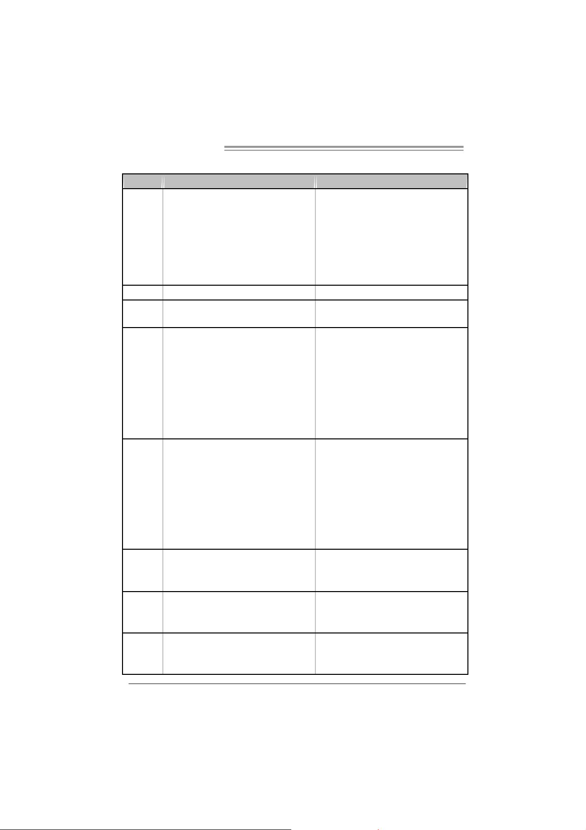
1.4 REAR PANEL CONNECTORS (FOR VER 5.X)
PS/2
Mouse
LAN
Audio Jack
Center
Rear
Side
USBX2
Line In
Line Out
Mi c In
PS/2
Keyboard
COM1 USBX2 USBX2
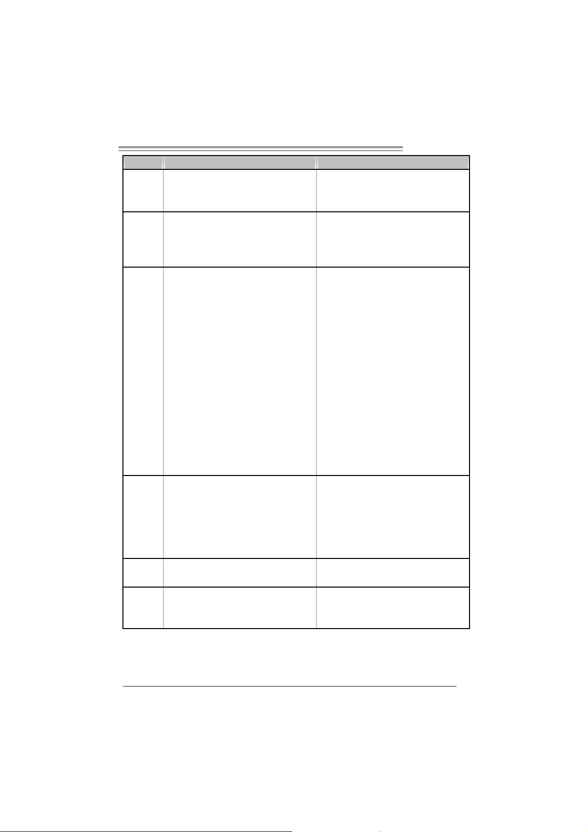
1.5 REAR PANEL CONNECTORS (FOR VER 6.X)
PS/2
Mouse
PS/2
Keyboard
Since the audio chip supports I ntel High Definition Audi o Specification, the function of each
audio jack can be defined by software. The input / output function of each audio jack list ed
above represents t he default setti ng. Howev er, when c onnecting external microphone to the
audio port, pl eas e us e the Line In (blue) and Mic In (Pi nk) audio jac k.
COM1 USBX2 USBX2
USBX2
LAN
Line In /
Surround
Line Out
Mic In 1/
Bass / Center
4
Page 7
P965 775
)
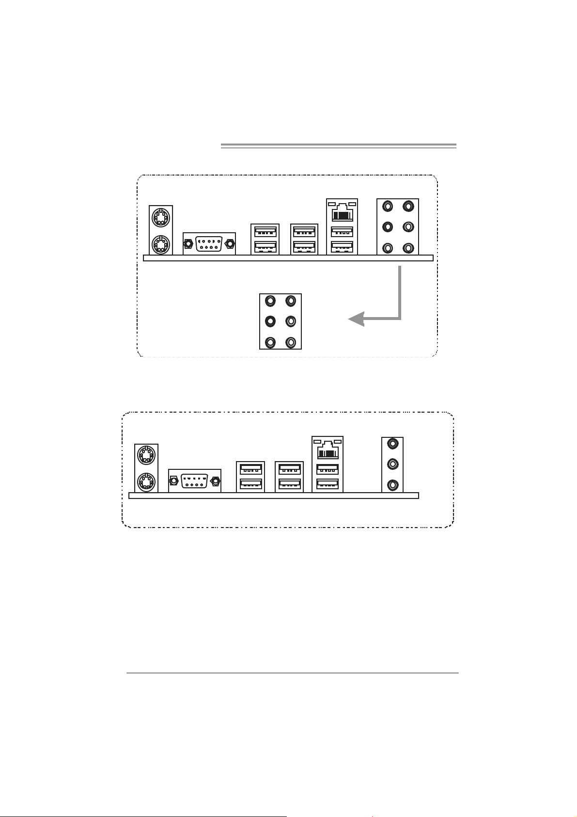
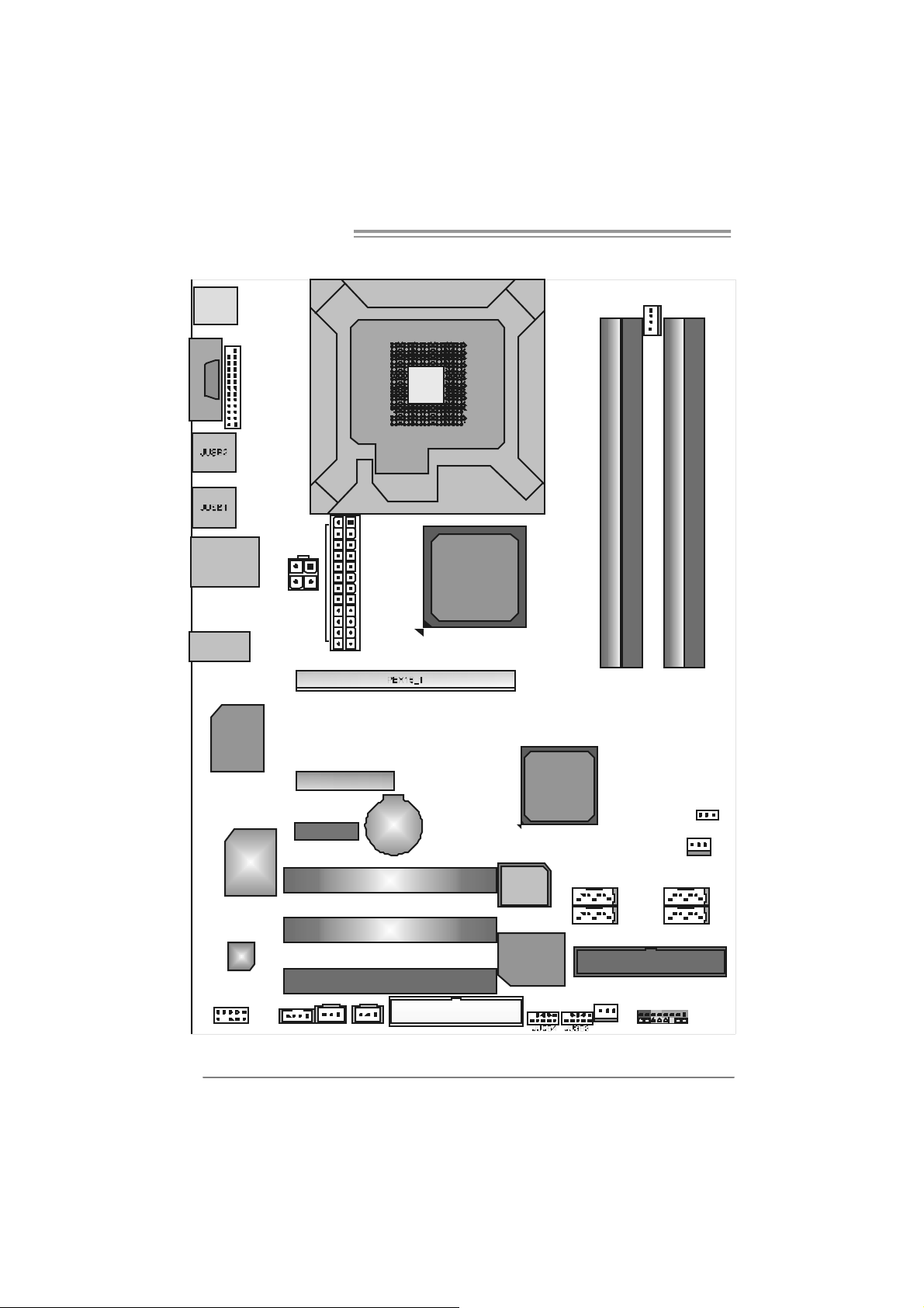
1.6 MOTHERBOARD LAYOUT (FOR VER 5.X)
JKBM S1
J PRNT1
C
O
JCOM 1
M
1
JRJ45USB1
JAUDIO1
Super
I/O
JATX PWR1
JATX PWR2
PEX4_1
PEX1_1
LGA775
CPU1
BAT1
Intel
P965
Intel
ICH8
JCFAN1
DDR2_A 1
DDR2_B 1
DDR2_A 2
DDR2_B 2
JCMOS1
IDE1
JPANEL1
JS FAN1
SATA1
SATA2SATA4
LAN
CODEC
JAUDIOF1
Note: represents the 1■
JSPDIF_OUT 1
JCDIN1(Optional
PCI1
PCI2
PCI3
JSPDIF_IN1( optiona l)
FDD1
st
pin.
BIO S
IDE
SATA3
JNFAN1
5
Page 8
Motherboard Manual
)
1.7 MOTHERBOARD LAYOUT (FOR VER 6.X)
JKBM S1
J PRNT1
COM1
JCOM 1
JRJ45USB1
JAUDIO1
Super
I/O
JATX PWR1
JATX PWR2
PEX4_1
PEX1_1
LGA775
CPU1
BAT1
Intel
P965
Intel
ICH8
JCFAN1
DDR2_A 1
DDR2_B 1
DDR2_A 2
DDR2_B 2
JCMOS1
IDE1
JPANEL1
JS FAN1
SATA1
SATA2SATA4
LAN
CODEC
JAUDIOF1
Note: represents the 1■
JSPDIF_OUT 1
JCDIN1(Optional
PCI1
PCI2
PCI3
JSPDIF_IN1( optiona l)
FDD1
st
pin.
BIO S
IDE
SATA3
JNFAN1
6
Page 9
P965 775
CHAPTER 2: HARDWARE INSTALLATION
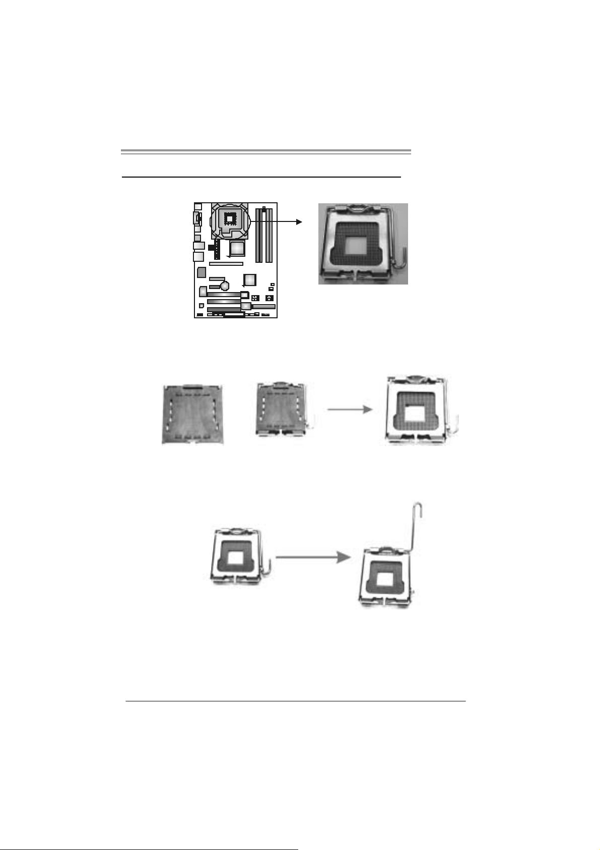
2.1 INSTALLING CENTRAL PROCE SSING UNIT (CPU)
Special Notice:
Remo v e Pin Cap before installatio n, and m ake goo d preservation
for future use. When the CPU is remov ed, cover the Pin Cap o n the
empty so cket to ensure pin legs won’ t be dam ag ed.
Pin Cap
Step 1: Pull the socket locking lever out from the socket and then raise
the lever up to a 90-degree angle.
7
Page 10
Motherboard Manual
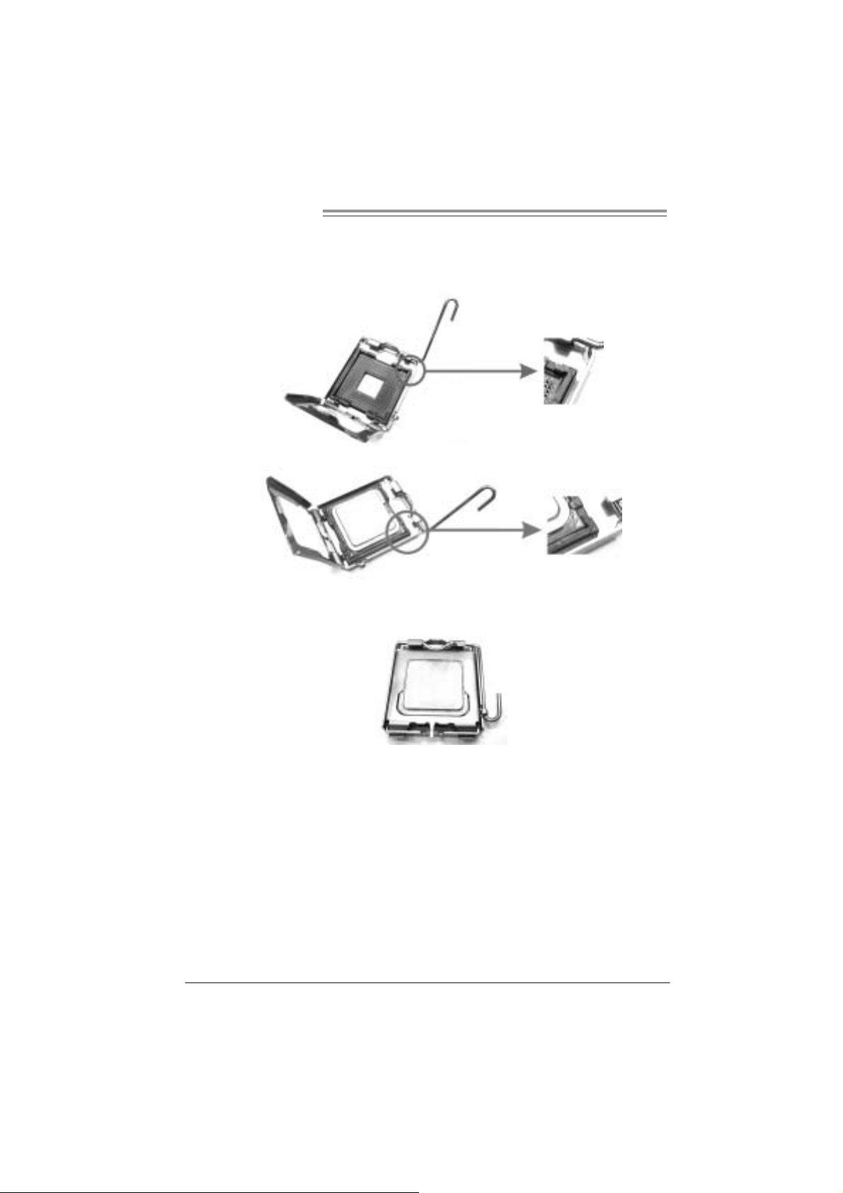
Step 2: Look for the triangular cut edge on socket, and the golden dot on
CPU should point forwards this triangular cut edge. The CPU will
fit onl y in the correct orientation.
Step 2-1:
Step 2-2:
Step 3: Hold the CPU down firml y, and then l ower the lever to l ocked
position to complete th e installati o n.
Step 4: Put the CPU Fan and heatsink assembly on the CPU and buckle i t
on the retenti on frame. Connect the CPU FAN power cable into
the JCFAN1. This complete s the installation.
8
Page 11
P965 775
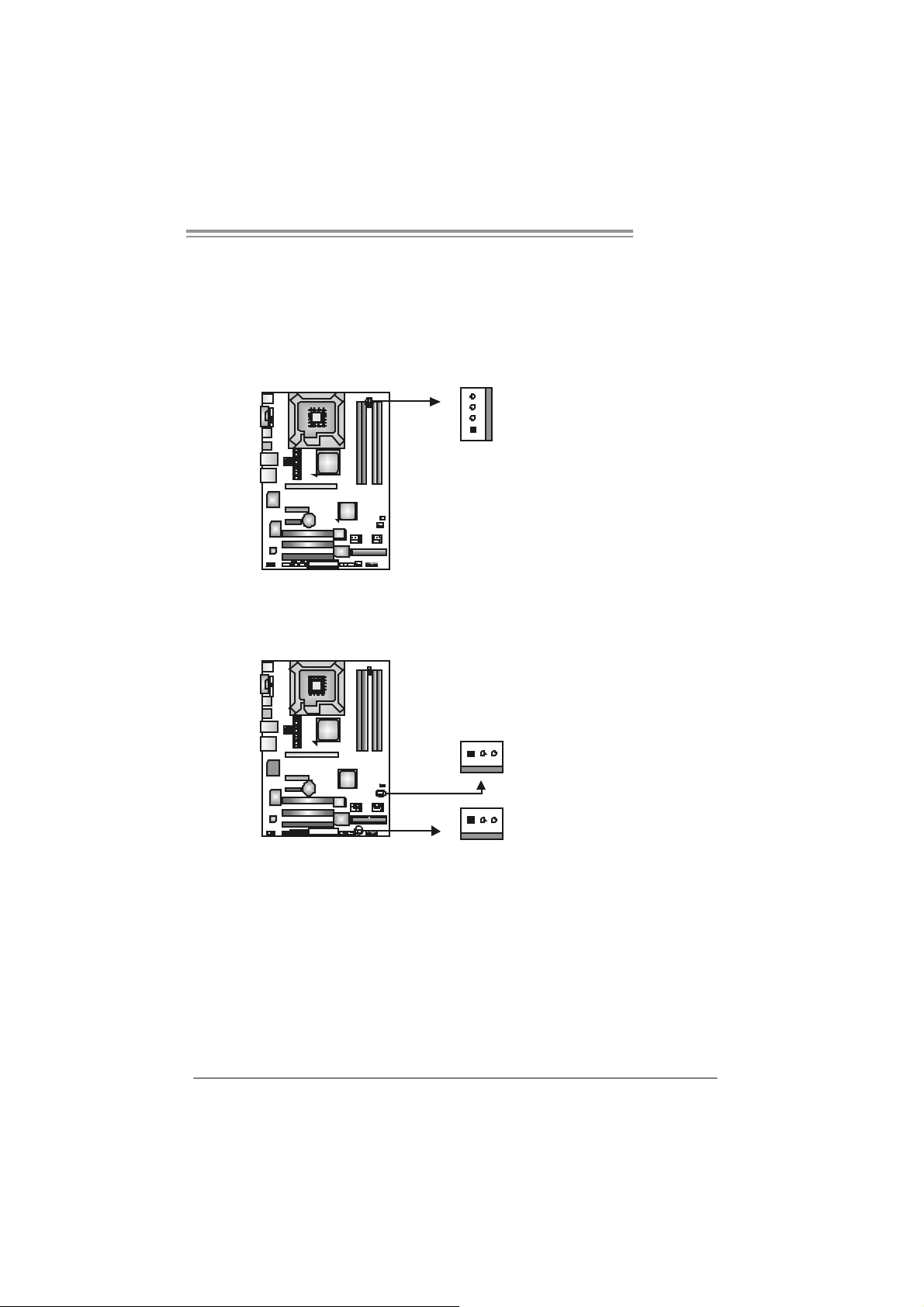
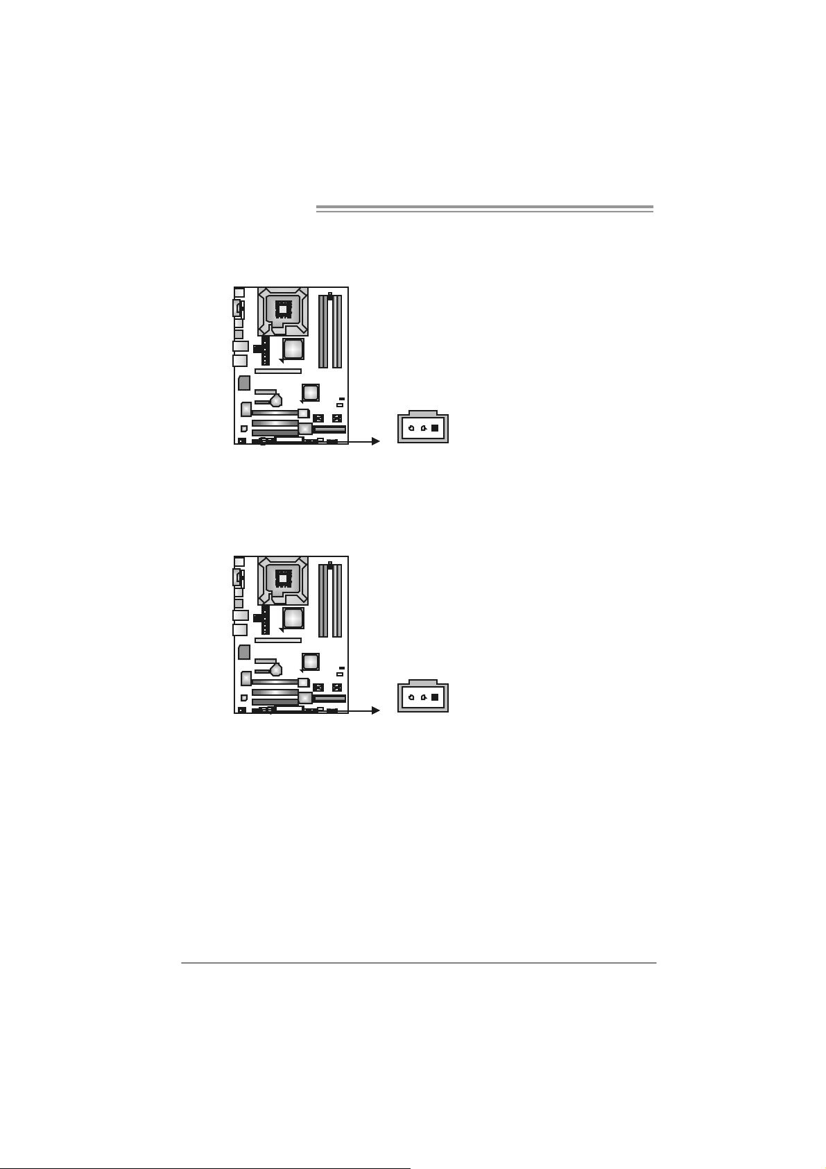
2.2 FAN HEADERS
These fan headers support cooling-fans bui lt in the com puter. The fan
cable and connector may be different according to the fan m anufacturer.
Connect the fan cable to the connector while matching the black wire to
pin#1.
JCFAN1: CPU Fan Header
4
JCFAN1
1
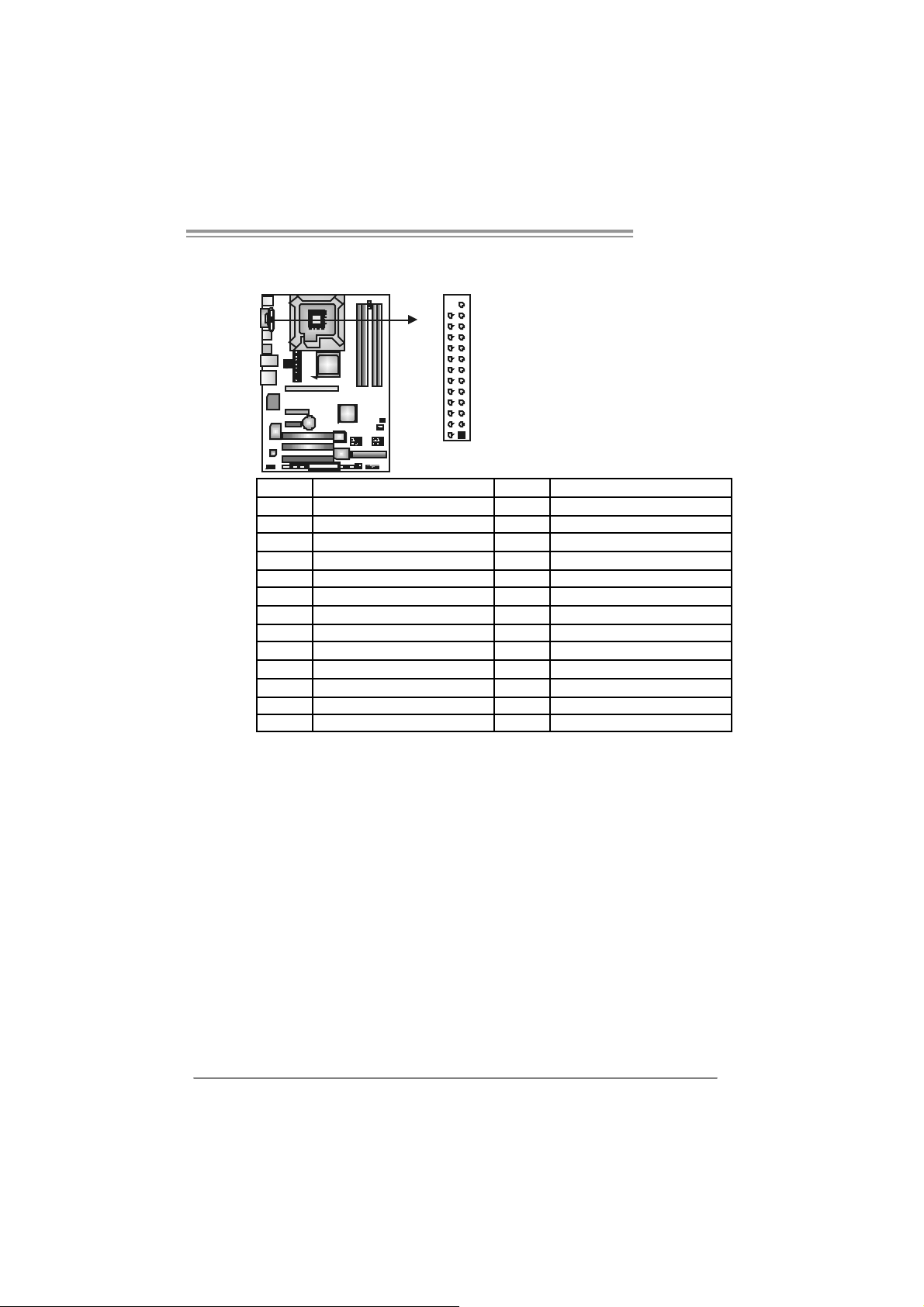
JSFA N1: System F an Head er
JNFAN1: Northbridge Fan Header
13
JSFAN1
13
JNFAN1
Note:
The JNFAN1 and JSFAN1 s upport 3-pin head c onnect or. When c onnecting with wires
onto connectors, please note that the red wire is the positive and should be c onnect ed to
pin#2, and the bl ac k wire is Ground and s hould be c onnected to GND.
Pin
Assignment
1 Ground
2 +12V
3
FAN RPM rate
sense
4 Smart Fan
Control
Pin
Assignment
1 Ground
2 +12V
3 FAN RPM rate
sense
9
Page 12
Motherboard Manual
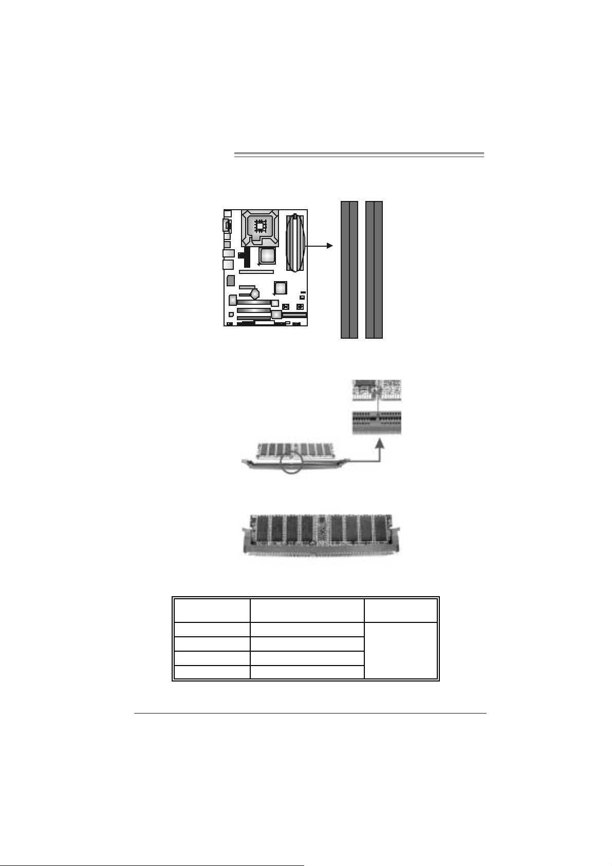
2.3 INSTALLING SYST EM MEMORY
A. Me mo ry Modu le s
DDR2_A1
DDR2_B1
DDR2_A2
DDR2_B2
1. Unlock a DIMM slot by pressing the retaining clips outward. Align a
DIMM on the slot such that the notch on the DIMM m atches the
break on the Slot.
2. Insert the DIMM verti cally and firml y into the sl ot until the retaining
chip snap back in place and the DIMM is properly seated.
B. Memory Capacity
10
DI MM Socket
Location
DDR2_A1 256MB/512MB/1GB/2GB
DDR2_A2 256MB/512MB/1GB/2GB
DDR2_B1 256MB/512MB/1GB/2GB
DDR2_B2 256MB/512MB/1GB/2GB
DDR Module
To t al Me m o r y
Size
Max i s 8 G B.
Page 13
P965 775
B. Du al C ha nnel Memory installation
To t rigger t he Dual C hannel func t ion of t he mot herboard, the memory module
must mee t the following requirement s:
Install memory m odule of the s am e density in pairs , shown in t he f ollowing
table.
Du al Channel Statu s
Enabled O X O X
Enabled X O X O
Enabled O O O O
(O means memory installed, X m eans memory not installed.)
The DRAM bus width of the m emory module must be the same (x8 or
x16)
DDR2_A1
DDR2_A2 DDR2_B1 DDR2_B2
11
Page 14
Motherboard Manual
2.4 CONNECTORS AND SLOTS
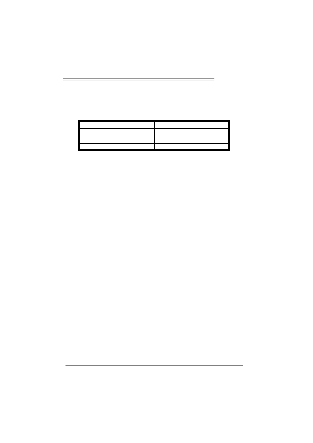
FDD1: Flo ppy Disk Connector
The motherboard prov ides a standard f loppy disk c onnector t hat supports 360K,
720K, 1. 2M, 1.44M and 2. 88M f loppy disk ty pes. This connector support s the
provided f loppy driv e ribbon c ables.
33 1
IDE1: Hard Disk C onnec tor
The motherboard has a 32-bit Enhanced PCI IDE Cont roller that provides PIO
Mode 0~4, Bus Master, and U lt ra DMA 33/66/100/133 f unctionality.
The IDE connector c an c onnect a mas t er and a s lave driv e, so y ou can c onnec t
up to two hard dis k drives .
34
2
39
1
240
12
Page 15
P965 775
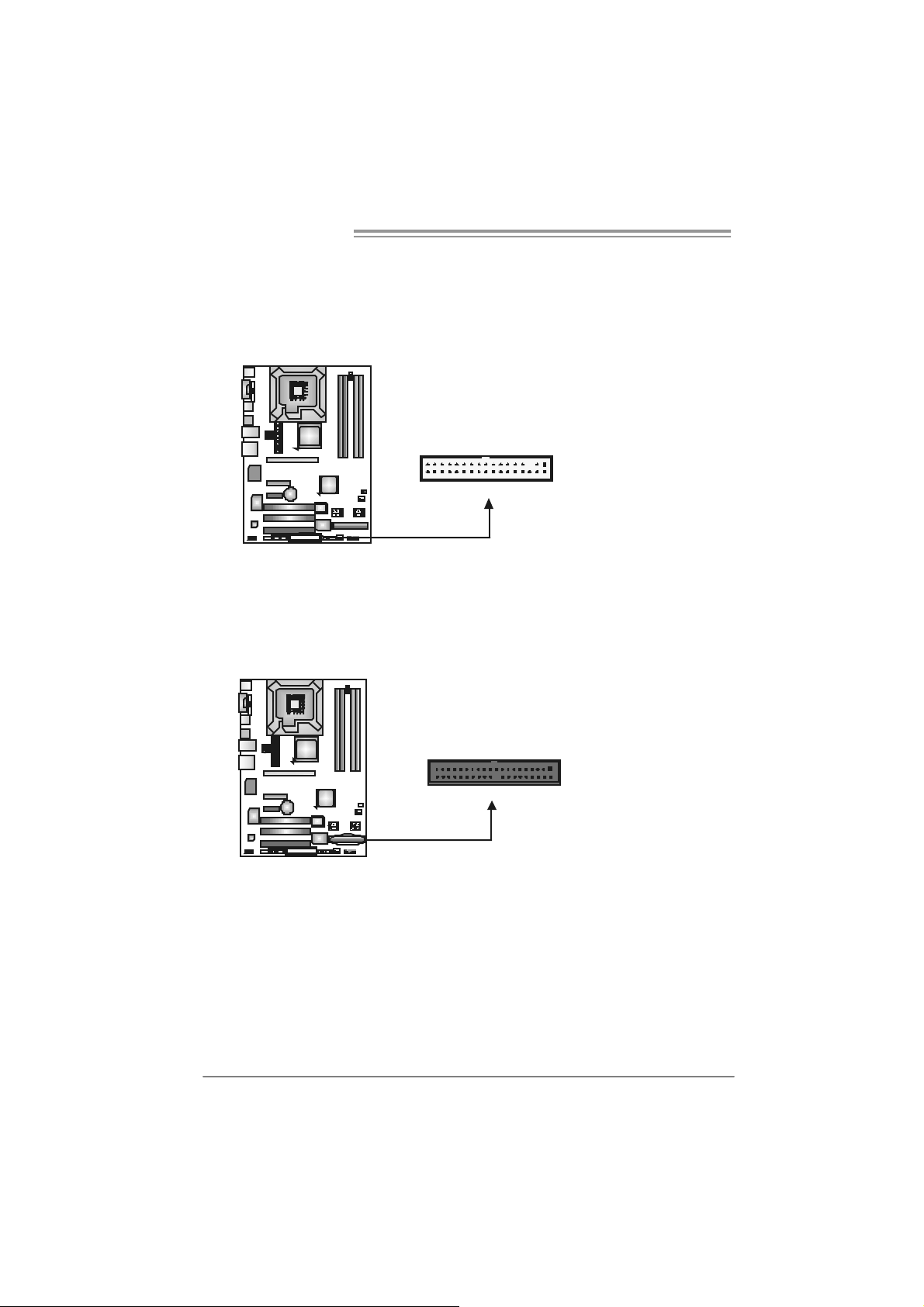
PEX16_1: PC I-Express x16 Slot
- PC I -Ex pres s 1.0a com pliant.
- Maxim um t heoret ical realized bandwidth of 4GB/s sim ult aneously per
direct ion, for an aggregate of 8GB/ s totally.
PE X4_1: P CI-Expres s x4 Slot
- PC I -Ex pres s 1.0a com pliant.
- Maxim um t heoret ical realized bandwidth of 1GB/s sim ult aneously per
direct ion, for an aggregate of 2GB/ s totally.
PEX1_1: PCI-Express Slot
- PC I -Ex pres s 1.0a com pliant.
PEX16_1
PEX4_1
PEX1_1
PCI1~PC I3: Peripheral Component In terconnect Slots
This mot herboard is equipped with 3 st andard PC I slots. PC I stands f or
Peripheral Com ponent I nt erc onnect, and it is a bus st andard for ex pans ion
cards . This PCI s lot is designat ed as 32 bits.
PCI1
PCI2
PCI3
13
Page 16
Motherboard Manual
_
CHAPTER 3: HEADERS & JUMPERS SETUP
3.1 HOW TO SETUP JUMPERS
The illustration shows how to set up j umpers. When the jumper cap is
placed on pins, the jumper is “close”, if not, that means the jumper is
“open”.
Pin opened Pin closed Pin1-2 closed
3.2 DETAIL SETT INGS
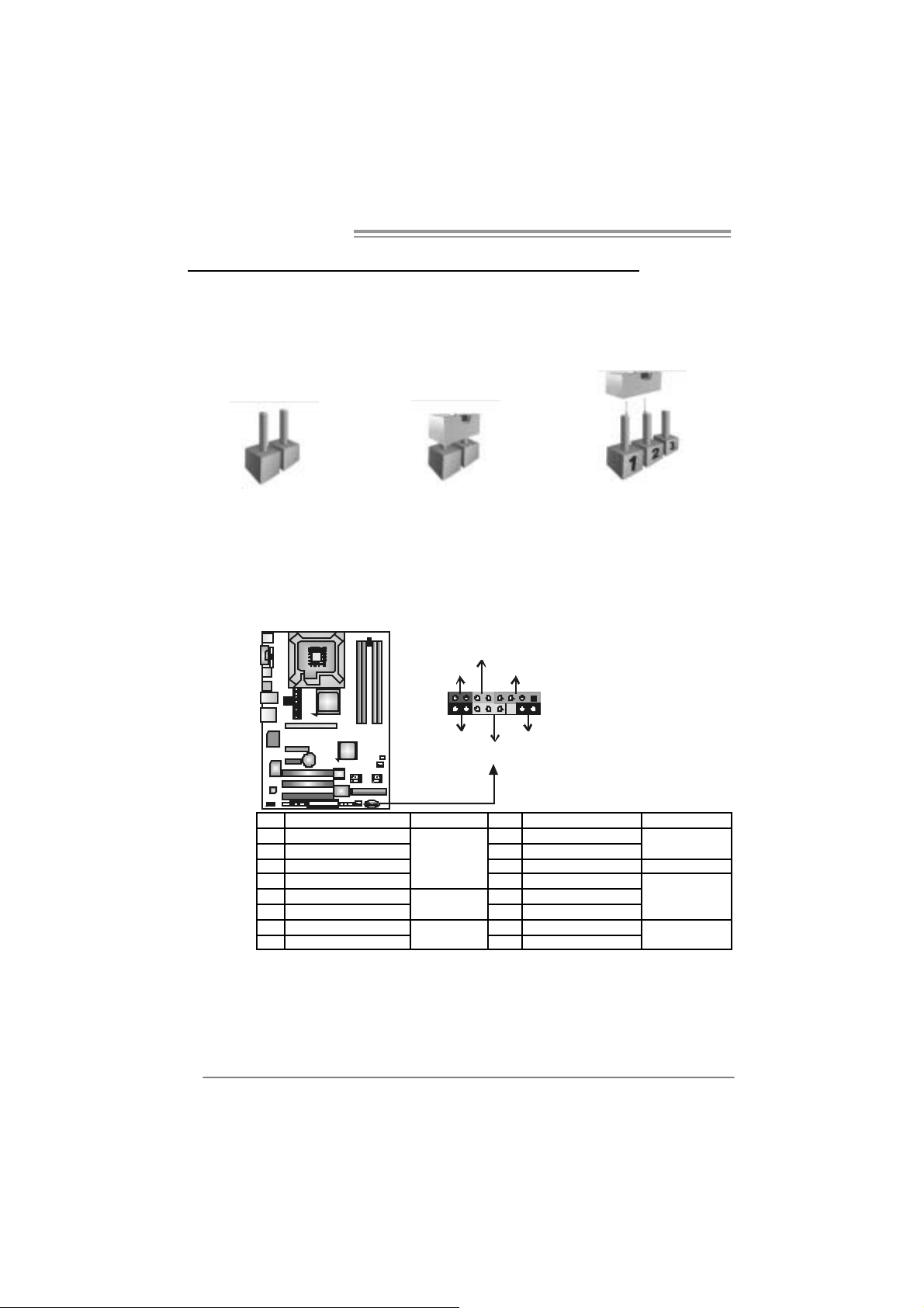
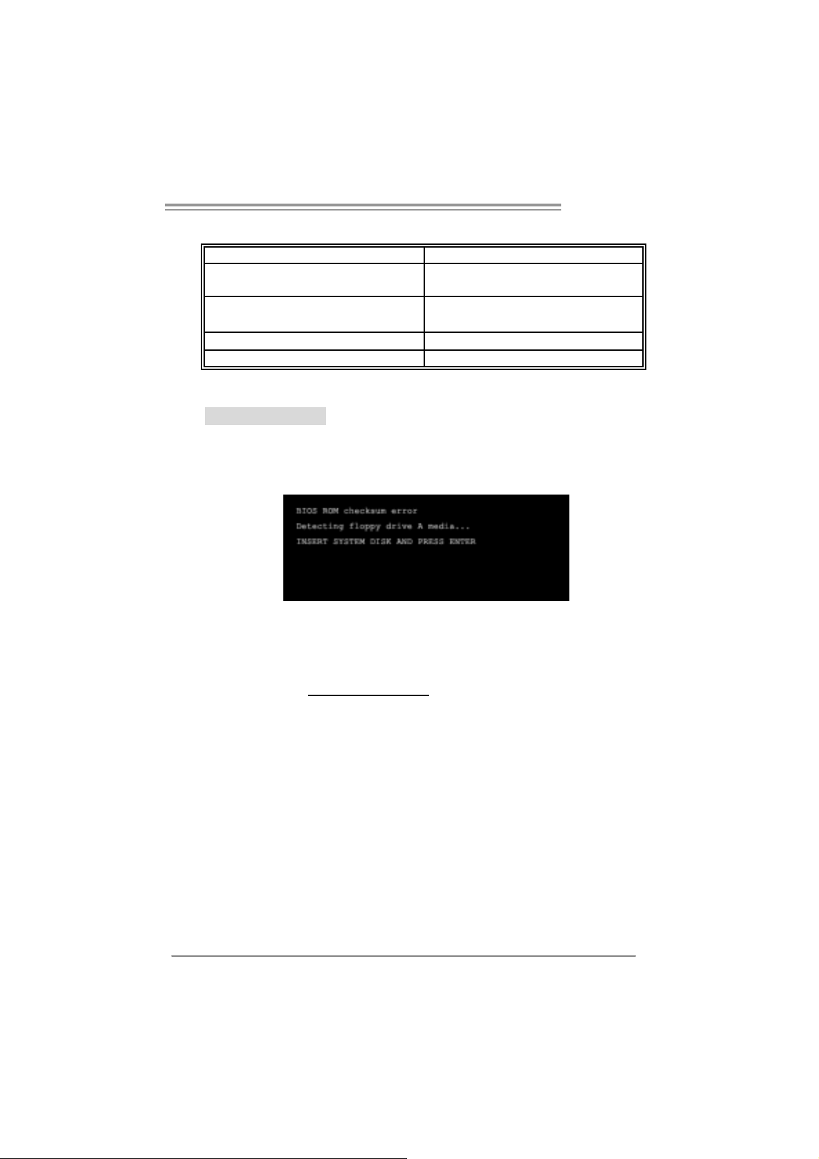
JPANEL1: Front Panel Heade r
This 16-pin connector includes Power-on, R eset, H DD LED, Power LED, Sleep
butt on and speak er c onnection. It allows us er to connect the PC case’s f ront
panel switch f unctions.
HLED
8
16
On/Off
RST
PWR
+--
LED
SPK
++
1
9
SLP
14
Pin Assignment Function Pin Assignment Functio n
1 +5V 9 Sleep control
2 N/A 10 Ground
3 N/A 11 N/A N/A
4 Speaker
5 HDD LED (+) 13 P ower LED (+)
6 HDD LED (-)
7 Ground 15 Power button
8 Reset control
Speaker
Connector
Hard drive
LED
Reset button
12 Power LED (+)
14 Power LED (-)
16 Ground
Sleep button
Powe r LED
Power-on button
Page 17
P965 775
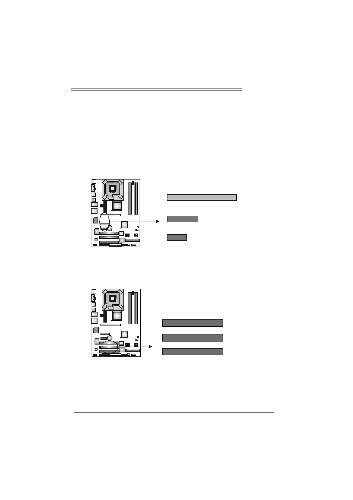
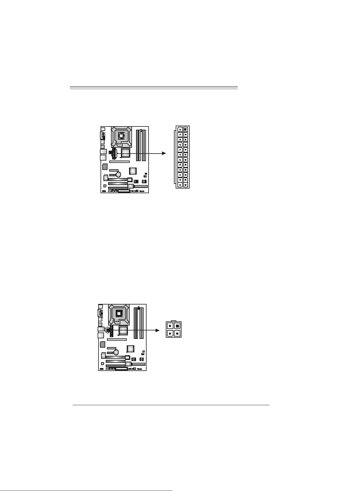
ATX Power Sourc e Co nnec tor: JAT XPWR2
JATXPW R 2 allows us er to c onnect 24-pin power c onnector on the ATX power
supply.
13
24
Pin Assignment Pin Assignment
1
12
13 +3.3V 1 +3.3V
14 -12V 2 +3.3V
15 Ground 3 Ground
16 PS_ON 4 +5V
17 Ground 5 Ground
18 Ground 6 +5V
19 Ground 7 Ground
20 NC 8 PW_OK
21 +5V 9 Standby Voltage+5V
22 +5V 10 +12V
23 +5V 11 +12V
24 Ground 12 +3.3V
JATXPW R1: ATX Power So u rce C onne ctor
By c onnecting this c onnector, it will provide +12V to CPU power circ uit.
12
3
4
Pin
Assignment
1 +12V
2 +12V
3 Ground
4 Ground
15
Page 18
Motherboard Manual
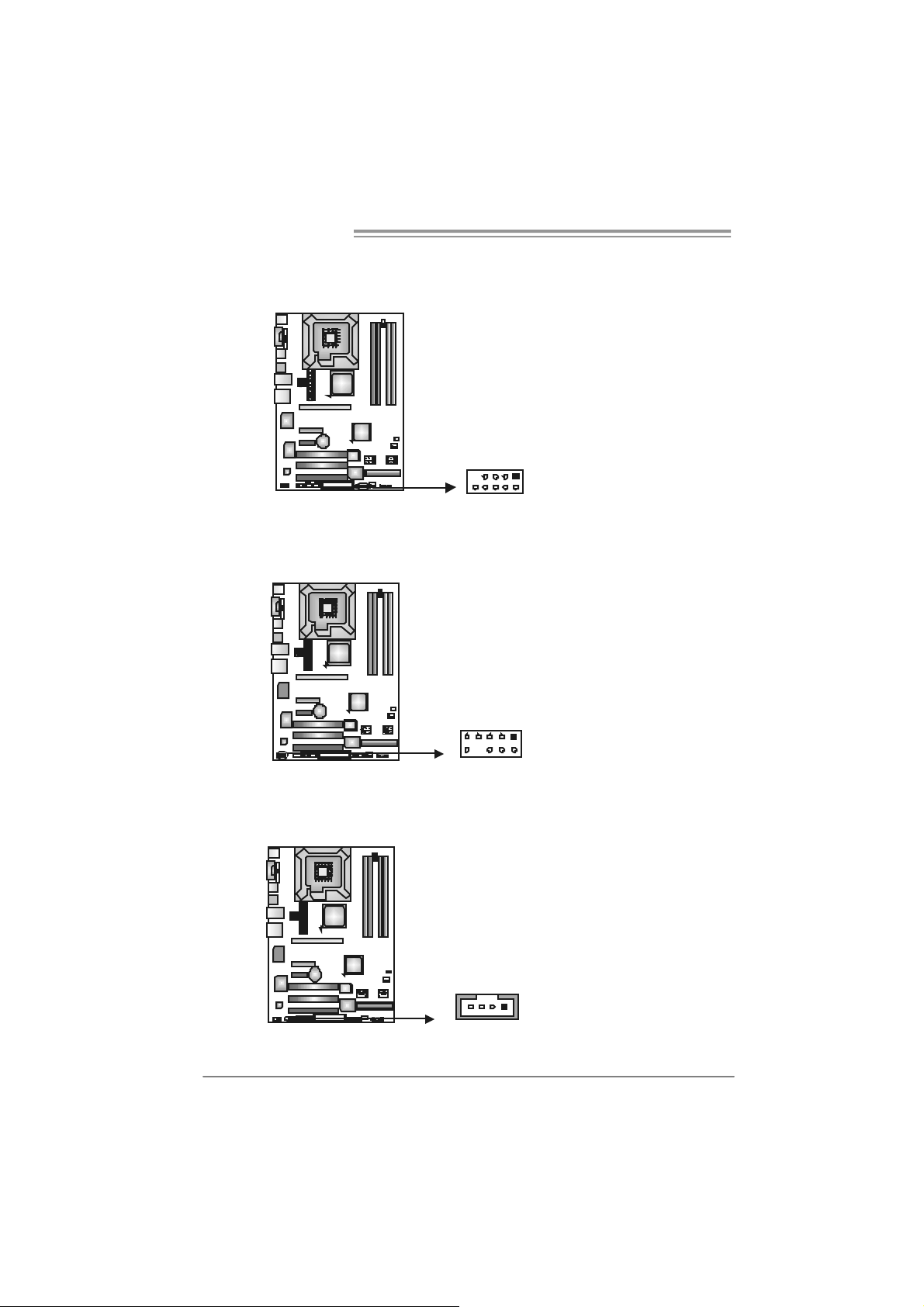
JUSB3/JUSB4: Headers for USB 2.0 Ports at Fron t Panel
This header allows us er t o connect addit ional USB cable on the PC front panel,
and also can be c onnec t ed wit h int ernal USB dev ic es, like USB card reader.
JUSB4 JUSB3
9
10
1
2
JAUDIOF1: Fron t Panel Audio Header
This header allows us er t o connec t the front audio out put c able with the PC front
panel. It will dis able t he output on back panel audio c onnectors.
Pin Assignment
9
10
1
2
10 Left line out/
JCDIN1: CD-R OM A udi o-in Connector (Op t ion al)
This connector allows us er to c onnect the audio s ourc e f rom the v ariaty dev ices,
like CD-R OM, D VD -ROM, PC I sound card, PCI TV t urner card etc..
14
1 Mic in/center
2 Ground
3 Mic power/Bass
4 Audio power
5 Right line out/
6 Right line out/
7 Reserved
8 Key
9 Left line out/
Pin
1 Left Channel Input
2 Ground
3 Ground
4 Right Channel Input
Assignment
Pin
1 +5V (fused)
2 +5V (fused)
3 USB4 USB5 USB+
6 USB+
7 Ground
8 Ground
9 Key
10 NC
Speaker out Right
Speaker out Right
Speaker out Left
Speaker out Left
Assignment
16
Page 19
P965 775
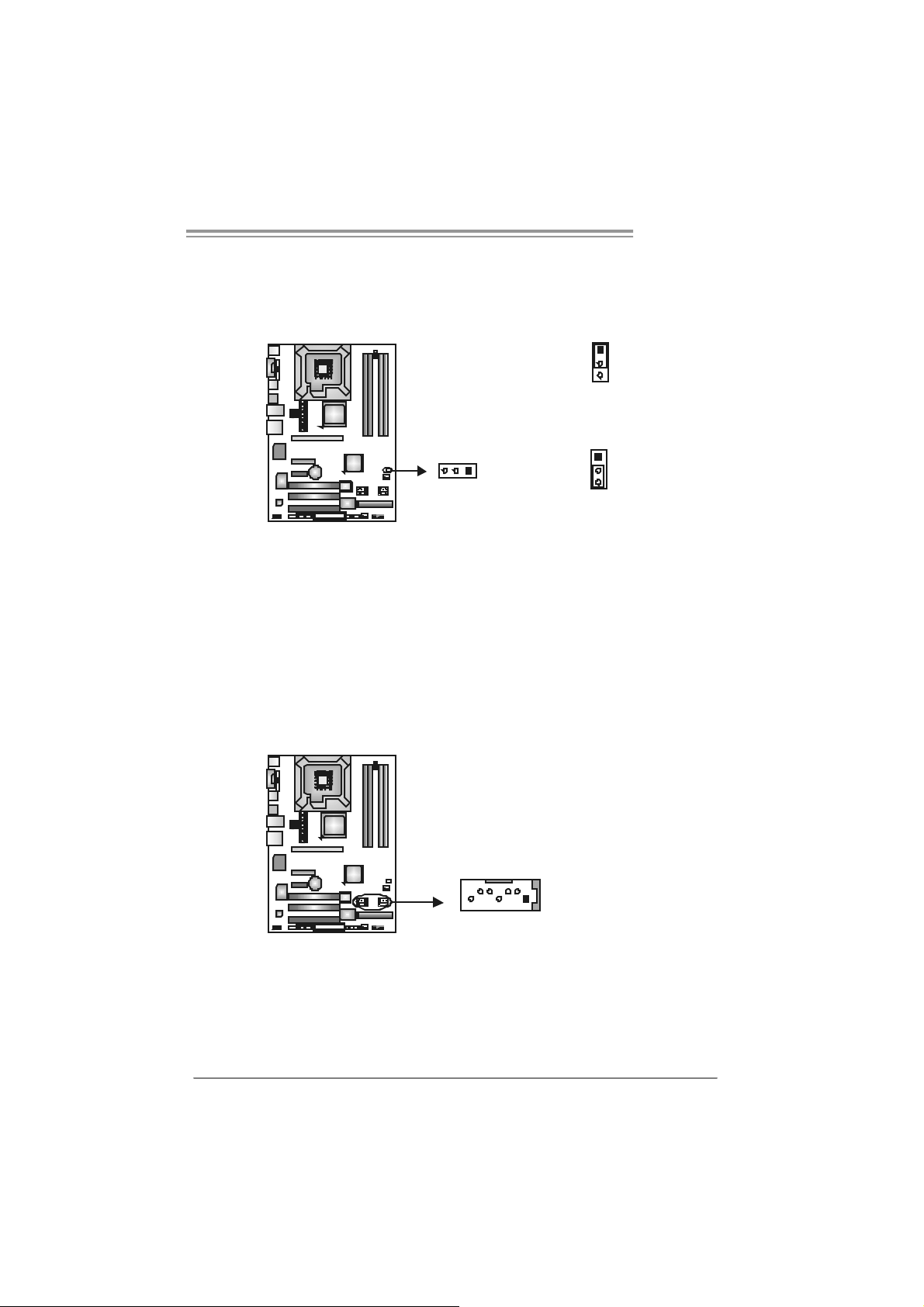
JCMOS 1 : C l ea r CMO S He a der
By plac ing the jum per on pin2-3, it allows us er to restore the BIOS saf e s etting
and the CMOS dat a, please caref ully f ollow t he procedures to avoid damaging
the m otherboard.
1
3
Pin 1-2 Close:
Normal Operation (default).
13
※ Clear CMOS Procedures:
1. R em ov e AC power line.
2. Set the jumper to “Pin 2-3 close”.
3. Wait for five seco n ds.
4. Set the jumper to “Pin 1-2 close”.
5. Power on the AC.
6. R es et your des ired pas s word or c lear t he CMOS dat a.
1
3
Pin 2-3 Close:
Clear CMOS data.
SATA1/S ATA2/SATA3/SATA4: Serial ATA Conne ctors
The motherboard has a PCI t o SATA C ont roller with 4 channels SATA int erf ace,
it satisfies the SATA 2.0 spec and with transfer rate of 3.0Gb/s.
Pin
Assignment
1 Ground
2 TX+
SATA3 SATA1
147
SATA4 SATA2
3 TX4 Ground
5 RX6 RX+
7 Ground
17
Page 20
Motherboard Manual
JSPD I F_O UT1 : Digital Audio-out Connec tor
This connector allows user t o c onnect the PCI bracket SPDIF output header.
13
JSPDIF_IN1: Digital Audio-in Connector (Optional)
This connector allows user t o c onnect the PCI bracket SPDIF input header.
Pin
Assignment
1 +5V
2 SPDIF_OUT
3 Ground
Pin
Assignment
1 +5V
2 SPDIF_IN
3 Ground
18
13
Page 21
P965 775
JPRNT1: Printer Port Con nector
This header allows y ou t o connector print er on t he PC.
25
12
Pin Assignment Pin Assignment
1 -Strobe 14 Ground
2 -ALF 15 Data 6
3 Data 0 16 Ground
4 -Error 17 Data 7
5 Data 1 18 Ground
6 -Init 19 -ACK
7 Data 2 20 Ground
8 -Scltin 21 Busy
9 Data 3 22 Ground
10 Ground 23 PE
11 Data 4 24 Ground
12 Ground 25 SCLT
13 Data 5 26 Key
19
Page 22

Motherboard Manual
CHAPTER 4: USEFUL HELP
4.1 DRIVER INSTALLATION NOTE
After you install ed your operating system, please insert the Fully Setup
Driver CD into your optical dri ve and install the dri ver for better system
perform ance.
You will see the fol lowing window after you i nsert the CD
The set up guide will au to detect yo ur motherboa rd and operati ng syste m.
Note:
If this window didn’t show up aft er you ins ert the Driver CD, please use file browser to
l ocate and execu te the fi l e SET UP.EXE under your opt ic al dr i ve.
A. Driver Installation
To install the dri ver, pl ease cli ck on the Driver i con. The setup guide will
list the compatible driver for your motherboard and operating system.
Click on each devi ce driver to launch the installati on program .
B. Software Installation
To install the software, pl ease cli ck on the Software icon. The setup guide
will list the software available for your system, click on each software titl e
to la unch the insta l lat io n pr ogr a m.
C. Manual
Asi de from the paperback manual, we al so provide manual in the Driver
CD. Cl i ck on the M anual icon to browse for available manual.
Note:
You will need Acrob at Reader to op en the man ua l file. Ple ase downloa d the latest version
of Acrobat Reader software from
http://www.adobe.com/products/a crobat /readstep2.html
20
Page 23
P965 775
4.2 AWARD BIOS BEEP CODE
Beep Sound Meanin g
One long beep f ollowed by t wo s hort
beeps
High-low siren sound CPU overheated
One Short beep when system boot-up No error found during POST
Long beeps every ot her s econd No DRAM detected or ins t all
Video card not f ound or v ideo card
mem ory bad
Sys t em will s hut down autom at ically
4.3 EXTRA INFORMATION
A. BIOS Update
After yo u fail to up d ate BIOS or BIOS is invaded b y virus, the
Boot-Block functi on will hel p to restore BIOS. If the fol lowing message
is shown after boot-up the system, it means the BIOS contents are
corrupted.
In this Case, please follow the procedure below to restore the BIOS:
1. Mak e a bootab le floppy d is k.
2. Download the Flash Uti lity “AWDFLASH.exe” from the Biostar
website: www.bi o star.com .tw
3. Confirm motherboard model and download the respectively BIOS
fr om Bi os t ar websit e.
4. Copy “AWDFLASH.exe” and respecti vel y BIOS into floppy disk.
5. Insert the bootable di sk into floppy drive and press Enter.
6. Sy stem will boot -up to DOS p rompt.
7. Type “Awdflash xxxx.bf/ sn/py/ r” in DOS prompt.
(xxxx means B IOS nam e.)
8. Sy stem will update B IOS au tomati c ally an d re sta rt.
9. The BIOS has been re cov ered an d will work pro pe rly.
21
Page 24

Motherboard Manual
B. CPU Overheated
If the system shutdown automatically after power on system for
seconds, that means the CPU protection function has been activated.
When the CPU i s over heated, the motherboard wi ll shutdown
automatically to avoid a damage of the CPU, and the system may not
power on again.
In this case, please double check:
1. The CPU cooler surface is placed evenly with the CPU surface.
2. CPU fan is rotated normall y.
3. CPU fan speed is ful filling with the CPU speed.
After confirmed, pl ease follow steps below to rel ief the CPU protection
function.
1. Remove the power cord from power suppl y for seconds.
2. Wai t for seconds.
3. Plug in the power cord and boot up the system.
Or you can:
1. Clear the CMOS data.
(See “Close CMOS Header: JCMOS1” section)
2. Wai t for seconds.
3. P ower on the syst em again.
22
Page 25

P965 775
e
4.4 TROUBLESHOOTING
Probable Solution
1. N o power to t he sy stem at all
Power light don’t illuminat e, fan
inside power s upply does not turn
on.
2. I ndic at or light on k ey board does
not t urn on.
Sys t em inoperat iv e. Key board light s
are on, power indic at or lights are lit,
and hard drive is spinning.
Sys t em does not boot f rom hard disk
drive, c an be booted from optical driv e.
Sys t em only boot s from optical driv e.
Hard disk can be read and applic ations
can be used but boot ing from hard dis k
is imposs ible.
Screen m essage say s “Inv alid
Conf igurat ion” or “C MOS Failure.”
Cannot boot sys t em after inst alling
sec ond hard driv e.
1. Make s ure power cable is
sec urely plugged in.
2. Replace cable.
3. Contact technical support.
Us ing even pres s ure on both ends of
the DIMM, press down f irm ly unt il the
module s naps int o plac e.
1. C hec k cable running from disk to
disk controller board. Make s ure
both ends are s ec urely plugged
i n; c hec k the driv e t y pe in the
standard CMOS setup.
2. Bac k ing up t he hard driv e is
ext rem ely im port ant . All hard
disk s are c apable of breaking
down at any t im e.
1. Bac k up dat a and applic at ions
files.
2. R ef orm at t he hard driv e.
Re-ins t all applicat ions and data
using backup disks.
Rev iew sys t em ’s equipment. Mak e sur
correc t inform at ion is in s et up.
1. Set m as t er/slave jum pers
correctly.
2. R un SETUP program and selec t
correc t drive types. Call t he driv e
manufacturers for co mpatibili t y
with other drives.
23
Page 26

Motherboard Manual
CHAPTER 5: WARPSPEEDER™
5.1 INTRODUCTION
[WarpSpeeder™], a new powerful control uti lity, features three
user-friendly functions including Overclock Manager, Overvoltage
Manager, and Hardware Monitor.
Wi th the Overclock Manager, users can easi ly adjust the frequency they
prefer or they can get the best CPU performance with just one click. The
Overvol tage Manager, on the other hand, helps to power up CPU core
vol tage and Me mor y v ol tage. The co o l H ardw are Mo ni tor s martly indicates
the temperatures, voltage and CPU fan speed as wel l as the chi pset
information. Al so, in the About panel, you can get detail descri pti ons about
BIOS model and chipsets. In addition, the frequency status of CPU,
mem ory, AGP and PCI along with the CPU speed are synchroni cally
s how n on our ma i n p an el .
Moreover, to protect users' computer systems i f the setting i s not
appropriate when testing and results i n system fail or hang,
[WarpSpeeder™] technology assures the system stability by automatically
rebooting the computer and then restart to a speed that is either the
ori ginal system speed or a suitable one.
5.2 SYS TEM REQUI REMENT
OS Support: Windows 98 SE, Windows Me, Windows 2000, Windows XP
DirectX: DirectX 8.1 or above. (T he Windows XP operating system
includes DirectX 8.1. If you use Windows XP, you do not need to i nstal l
Dir ec tX 8.1.)
24
Page 27
P965 775
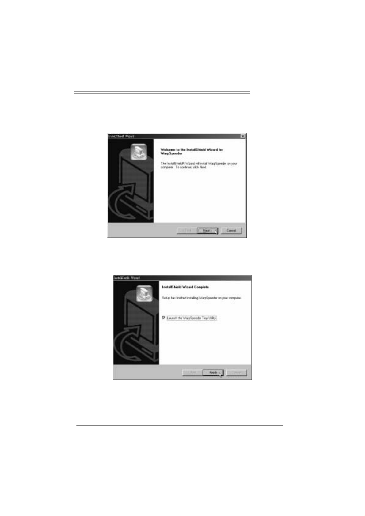
5.3 INSTALLATION
1. Execute the setup execution file, and then the following di alog will pop
up. Please click “Next” button and follow the default procedure to
install.
2. When you see the followi ng dialog in setup procedure, it m eans setup
is completed. If the “Launch the WarpSpeeder T ray Utility” checkbox
is c hecked , the Tra y Icon utili ty and [ WarpSpe eder™ ] utility will be
automatically and immediately launched after you click “Finish”
button.
Usage:
The following figures are just only for reference, the screen printed in
this user manual will chan ge ac c ording to your mothe rbo ard on hand.
25
Page 28

Motherboard Manual
5.4 WARPSPEEDER™
1. Tray Icon:
Whenever the Tray Icon utility is launched, it will displa y a little tray
icon on the right side of Windows Taskbar.
This utility i s responsible for conveniently i nvoking [WarpSpeeder™]
Utility. You can use the mouse by clicking the left button in order to
invoke [WarpSpeeder™] di rectly from the little tray icon or you can
ri ght-click the little tray icon to pop up a popup menu as following
figure. The “Launch Utility” item in the popup menu has the same
fun c tio n as mou se left-click on t ray icon and “Exi t” item will close
T ray Icon utili ty if selected.
26
Page 29

P965 775
2. Main Panel
If y ou click the tray icon, [WarpSpe ede r™] utility will be invoked.
Please refer to the follo wi ng fi gure; the utili ty’s first window you will
see is Main Panel.
Main Panel contains features as follows:
a. Display the CPU Speed, CPU e xter nal clock, M emor y clock, AGP clock,
and PCI cl ock information.
b. Contains About, Voltage, Overclock, and Hardware Monitor Buttons for
invoking respective panels.
c. With a user- fr ie nd ly S t atus An im at io n, it c an represent 3 overc loc k
percentage stages:
Man walking→overclock percentage from 100% ~ 110 %
Panther running→overclock percentage from 110% ~ 120%
Ca r rac ing→overclock percentage from 120% ~ above
27
Page 30

Motherboard Manual
3. Vol tage Pa nel
Click the Volta ge bu tton in Main Pa nel, the butt on will be highlighted
and the Vol ta ge Pa ne l will slide out to up as the f ollowing figure .
In this panel, you can decide to increase CPU core vol tage and
Memory voltage or not. The defa ult se tting is “No”. If you wan t to ge t
the best performance of overclocking, we recommend you click the
option “Yes”.
28
Page 31

P965 775
4. Over clock Panel
Click the O verclock button in Main Panel, the button will be
highlighted and the Overclock Panel will slide out to left as the
fol l owi ng f igur e.
Overclock Panel cont ains the these fea ture s:
a. “–3MHz button”, “-1MHz button”, “+1MHz button”, and “+3MHz button”:
provide user the abili ty to do real-time overclock adjustment.
Warning:
Manually overclock is pot ent ially dangerous, es pec ially when t he
overclocking perc entage is ov er 110 %. We s t rongly recommend y ou
verify ev ery s peed y ou overclock by c lick the Verify butt on. Or, you c an
just click Aut o ov erclock but t on and let [WarpSpeeder™] aut om atically
gets the best res ult for y ou.
b. “Recovery Dialog button”: Pop up the following dialog. Let user sel ect
a restoring way i f system need to do a fail-safe reboot.
29
Page 32

Motherboard Manual
c. “Auto-overclock button”: User can cli ck this button and
[Wa rpS peeder™] will set the best and sta ble performance and
frequency automati cally. [WarpSpeeder™] utility will execute a
serie s of testing until syst em f ail. Then syste m will do fa il-saf e
reboot by using Watchdog function. After reboot, the
[WarpSpeeder™] utility will restore to the hardware defaul t
setting or load the veri fied best and stable frequency according
to th e Recovery Di alog’s setting .
d. “Veri fy button”: User can click this button and [WarpSpeeder™]
will proceed a testing for current frequency. If the testing i s ok,
then the current freq uency will be save d into syste m registry. If
the testing fail, system will do a fail-safe rebooti ng. After reboot,
the [WarpSpeeder™] uti lity will restore to the ha rdware defau lt
setting or load the veri fied best and stable frequency according
to th e Recovery Di alog’s setting .
Note:
Becaus e the t esting program s, invoked in Aut o-overclock and Verify,
include D irectDraw, D irec t 3D and D irectShow tests, the D irectX 8.1 or
newer runtime library is required. And pleas e m ak e sure y our display
card’s color depth is High c olor (16 bit ) or True color( 24/32 bit ) t hat is
required for Direct3D rendering.
5. Hardware Monitor Panel
Click the Hardware Mo nitor button in Main Pa nel, the button will be
highlighted and the Hardware Monitor panel will slide out to left as
the fo l lowing f igur e.
In this panel, you can get the real-time status inform ation of your
syste m. The informa tio n will be ref reshed every 1 second.
30
Page 33

P965 775
6. About Panel
Click the “about” button in Main Panel , the button will be highlighted
and th e A b out Panel wil l s l id e out to up as the fo l lowing fig ur e.
In this panel, you can get model name and detail inform ation in hints
of all the chipset that are related to overclocking. You can also get
the mainboard’s BIOS model and the Versi on num ber of
[WarpSpeeder™] utility.
Note:
Because the overclock, overvoltage, and hardware moni tor features
are controlled by several separate chipset, [WarpSpeeder™] divide
these features to separate panels. If one chipset is not on board, the
cor r elative button i n M ain panel will be disabled, but will not i nte r fer e
other panels’ functi ons. T his property can make [WarpSpeeder™]
utility more robust.
31
Page 34

Motherboard Manual
APPENDENCIES: SPEC IN OTHER LA NGUAGE
GERMAN
Ver 5 . x Ver 6 . x
LGA 775
Int el Core2Duo / Core2Quad / Pentium 4 /
Pentium D / Celeron D Proz essoren mit bis zu
CPU
FSB 533 / 800 / 1066 MHz 533 / 800 / 1066 M Hz
Chipsatz
Super E/A
Arbeitss peich
er
IDE
SA TA II
LAN
3,8 GHz
Unterstützt Hyper-Threading / Execute Disable
Bit / Enhanced Intel SpeedStep® / Intel
Architect ure-64 / Ext ended Memory 64
Tec hnology / V irt ualization Technology
Int el P9 65
Intel ICH8
ITE 8712F
Bi etet die häufig verw endeten alten S uper
E/A-Funktionen.
Low Pin Count-Schnittstel le
Umgebungskontrolle,
Hardware-Überwac hung
Lüfterdrehzahl-Controller
"Smart Guardian"-Funktion von I TE
DDR2 DIMM-S teckplätz e x 4
Jeder DIMM unt erstützt 256/512MB / 1GB /2GB
DDR2.
M ax. 8G B Ar be it ss peic her
Dual-Kanal DDR2 Speic hermodul
Unt erstützt DDR 2 533 / 667 / 800 regist rierte
DIMMs. ECC DIMMs werden nicht unterstützt.
VIA VT6410
Ultra DMA 33 / 66 / 100 / 133 B us
Master-Modus
Unterstützt PIO-Modus 0~4,
I nt e gri ert e r S e ri al ATA - Con tr o ll e r
Datentransferrate bis zu 3Gb/s
Konform mit der SATA-Spezifikation V ersion 2. 0.
Realtek RTL 8110SC
10 / 100 Mb/s und 1Gb/s Auto-Negotiation
LGA 775
Int el Core2Duo / Core2Quad / Pentium 4 /
Pentium D / Celeron D Proz essoren mit bis zu
3,8 GHz
Unterstützt Hyper-Threading / Execute Disable
Bit / Enhanced Intel SpeedStep® / Intel
Architect ure-64 / Ext ended Memory 64
Tec hnology / V irt ualization Technology
Int el P9 65
Intel ICH8
ITE 8712F
Bi etet die häufig verw endeten alten S uper
E/A-Funktionen.
Low Pin Count-Schnittstel le
Umgebungskontrolle,
Hardware-Überwac hung
Lüfterdrehzahl-Controller
"Smart Guardian"-Funktion von I TE
DDR2 DIMM-S teckplätz e x 4
Jeder DIMM unt erstützt 256/512MB / 1GB /2GB
DDR2.
M ax. 8G B Ar be it ss peic her
Dual-Kanal DDR2 Speic hermodul
Unt erstützt DDR 2 533 / 667 / 800 regist rierte
DIMMs. ECC DIMMs werden nicht unterstützt.
VIA VT6410
Ultra DMA 33 / 66 / 100 / 133 B us
Master-Modus
Unterstützt PIO-Modus 0~4,
I nt e gri ert e r S e ri al ATA - Con tr o ll e r
Datentransferrate bis zu 3Gb/s
Konform mit der SATA-Spezifikation Version 2. 0.
Realtek RTL 8110SC
10 / 100 Mb/s und 1Gb/s Auto-Negotiation
32
Page 35

P965 775
Ver 5 . x Ver 6 . x
Halb-/ Vollduplex-Funkt ion Halb-/ Vollduplex-Funkt ion
HD
Audio-Unters
tützung
Steckplätze
Onboard-Ans
chluss
Rückseiten-E
/A
Platinengröße 220 mm (B) X 305 m m (L ) 220 m m (B) X 305 mm (L)
OS-Unterst üt
zung
ALC888
Unterstützt Intel High-Definition Audio
7.1-K anal-Audioaus gabe
PCI-Stec kplatz x3 PCI-Stec kplatz x3
PCI Express x16 Steckplatz x1 PCI Express x16 Steckplatz x1
PCI Express x4 Steckplatz x1 PCI Express x4 Steckplatz x1
PCI Express x 1-Steckplat z x1 PCI Express x 1-Steckplatz x1
Diske ttenlaufw e rkansc hl uss x 1 Di skett enl aufw erkanschl uss x1
Druc keranschluss A nschluss x1 Druckera nsc hluss Anschluss x 1
IDE-Anschluss x1 IDE-Anschluss x1
SATA-Anschluss x4 SATA-Anschluss x4
Fronttafelanschluss x1 Fronttafelanschluss x1
Fr ont -Audioansc hl uss x1 F ront-Audi oansc hl uss x1
CD-IN-Anschluss(optional) x1 CD-IN-Anschluss(optional) x1
S/PDIF- Ausgangsansc hluss x1 S/PDIF- Ausgangsanschluss x1
S/PDIF Eingangs anschluss(optional) x1 S/PDIF Eingangs anschluss(optional) x1
CPU-Lüfter-Sockel x1 CPU-Lüfter-Sockel x1
System-Lüfter-Sockel x2 System-Lüfter-Sockel x2
"CMOS löschen"-Sockel x1 "CMOS l ösc hen"-Sockel x1
US B-Ansc hl uss x2 US B-Ansc hl uss x2
Stromanschluss (24-polig) x1 Stromanschluss (24-polig) x1
Stromanschluss (4-polig) x1 Stromanschluss (4-polig) x1
PS/2-Tastatur x1
PS/2-Maus x1
Serieller Ansc hluss x1
LAN-Ansc hluss x1
US B-Ansc hl uss x6
Audi oa nschl uss x6
Wi ndows 2000 / X P / VISTA
Biostar behält sich das Recht vor, ohne
Ankündigung die Unterstützung für ein
Betriebssystem hinzuzufügen oder zu
entfernen.
ALC861VD
Unterstützt Intel High-Definition Audio
5.1-K anal-Audioaus gabe
PS/2-Tastatur x1
PS/2-Maus x1
Serieller Ansc hluss x1
LAN-Ansc hluss x1
US B-Ansc hl uss x6
Audi oa nschl uss x3
Wi ndows 2000 / X P / VISTA
Biostar behält sich das Recht vor, ohne
Ankündigung die Unterstützung für ein
Betriebssystem hinzuzufügen oder zu
entfernen.
33
Page 36

Motherboard Manual
FRANCE
Ver 5 . x Ver 6 . x
LGA 775
Processeurs Intel Core2Duo / Core2Quad /
Pentium 4 / Pentium D / Celeron D jusqu'à 3,8
GHz
UC
Bus frontal 533 / 800 / 1066 MHz 533 / 800 / 1066 MHz
Chipset
Super E/S
Mémoire
principale
IDE
SA TA II
LA N Realt ek RTL 8110SC Realtek RTL 8110SC
Prend en charge les technologies
Hyper-Threading / d'exécution de bit de
désactivation / Intel SpeedStep® optimisée/
d'archit ecture Intel 64 / de m ém oire étendue 64
/ de virt ualisation
Int el P9 65
Intel ICH8
ITE 8712F
Four nit la fonc tionnalité de Super E/S
patrimoniales la plus utilisée.
Interface à faible compte de broches
Initiatives de contrôle environnem entales,
Monit eur de matériel
Contrôleur de vitesse de vent ilateur
Fonction "Gardien intelligent" de l'ITE
Fentes DDR 2 DIMM x 4
Chaque DIM M prend en c harge des DDR2 de
256/512 M o 1Go /2Go
Capacité mémoire maximale de 8 Go
Modul e de mémoi re DDR2 à m ode à double voie
Prend en char ge la DDR2 533 / 667 / 800
Les DIMM à registres et DIMM avec code
correc teurs d' erreurs ne sont pas prises en
charge
VIA VT6410
Mode pr incipal e de Bus Ultr a DMA 33 / 66 / 100 /
133
Prend en c harge le mode PIO 0~4,
Cont r ôl eur Se rial ATA intégré :
Taux de transfert jusqu'à 3 Go/s.
Conforme à la spécification SATA Version 2.0
LGA 775
Processeurs Intel Core2Duo / Core2Quad /
Pentium 4 / Pentium D / Celeron D jusqu'à 3,8
GHz
Prend en charge les technologies
Hyper-Threading / d'exécution de bit de
désactivation / Intel SpeedStep® optimisée/
d'archit ecture Intel 64 / de m ém oire étendue 64
/ de virt ualisation
Int el P9 65
Intel ICH8
ITE 8712F
Four nit la fonc tionnalité de Super E/S
patrimoniales la plus utilisée.
Interface à faible compte de broches
Initiatives de contrôle environnem entales,
Monit eur de matériel
Contrôleur de vitesse de vent ilateur
Fonction "Gardien intelligent" de l'ITE
Fentes DDR 2 DIMM x 4
Chaque DIM M prend en c harge des DDR2 de
256/512 M o 1Go /2Go
Capacité mémoire maximale de 8 Go
Modul e de mémoi re DDR2 à m ode à double voie
Prend en char ge la DDR2 533 / 667 / 800
Les DIMM à registres et DIMM avec code
correc teurs d' erreurs ne sont pas prises en
charge
VIA VT6410
Mode pr incipal e de Bus Ultr a DMA 33 / 66 / 100 /
133
Prend en c harge le mode PIO 0~4,
Cont r ôl eur Se rial ATA intégré :
Taux de transfert jusqu'à 3 Go/s.
Conforme à la spécification SATA Version 2.0
34
Page 37

P965 775
/
Ver 5 . x Ver 6 . x
Prise en
charge
audio HD
Fentes
Connec teur
embarqué
E/S du
panneau
arrière
Dim ensions
de la carte
Support SE
10 / 100 Mb/s et 1 Gb/s négociation automatique
Half / Full duplex capability
ALC888
Prise en charge de l'audio haute définition Intel
Sortie audio à 7. 1 voies
Fente PCI x3 Fente PCI x3
Slot PCI Express x16 x1 Slot PCI Express x16 x1
Slot PCI Express x 4 x1 Slot PCI Express x 4 x1
Slot PCI Express x 1 x1 Slot PCI Express x 1 x1
Connec teur de disquette x1 Connect eur de disquette x1
Connecteur de Port d'imprimante x1 Connecteur de Port d'imprimante x1
Connec teur IDE x1 Connec teur IDE x1
Connec t eur SATA x4 Conn ecteur SATA x4
Connec teur du panneau avant x1 C onnect eur du panneau avant x1
Connec teur Audio du panneau avant x1 Connect eur Audio du panneau avant x1
Connecteur d'entrée CD(en opt ion) x1 Connecteur d'entrée CD(en option) x1
Connecteur de sortie S/PDIF x1 Connecteur de sortie S/PDIF x1
Connecteur d'entrée S/PDIF(en option) x1 Connecteur d'entrée S/PDIF(en option) x1
Embase de ventilat eur UC x1 Em bas e de ventilat eur UC x1
Embase de ventilat eur syst ème x2 Embas e de ventilateur systèm e x2
Embas e d'effacement CMO S x1 Embase d'effacement CMO S x1
Connec teur US B x2 Connec teur USB x2
Connecteur d'aliment ation x1
(24 broches)
Connecteur d'aliment ation x1
(4 broches)
Clavier PS/2 x1
Souris PS/2 x1
Port série x1
Port LAN x1
Port USB x6
Fiche audio x6
220 mm (l) X 305 mm (H) 220 mm (l) X 305 mm (H)
Wi ndows 2000 / X P / VISTA
Biostar s e réserve le droit d'ajouter ou de
supprimer le support de S E avec ou sans préavis.
100 Mb/s et 1 Gb/s négociation automatique
10
Half / Full duplex capability
ALC861VD
Prise en charge de l'audio haute définition Intel
Sortie audio à 5. 1 voies
Connecteur d'aliment ation x1
(24 broches)
Connecteur d'aliment ation x1
(4 broches)
Clavier PS/2 x1
Souris PS/2 x1
Port série x1
Port LAN x1
Port USB x6
Fiche audio x3
Wi ndows 2000 / X P / VISTA
Biostar s e réserve le droit d'ajouter ou de
supprimer le support de S E avec ou sans préavis.
35
Page 38

Motherboard Manual
/
p
/
/
p
/
ITALIAN
Ver 5. x Ver 6.x
LGA 77 5
Processore Intel Core2Duo / Core2Quad /
Pentium 4
CPU
FS B 533 / 800 / 1 06 6 MHz 533 / 800 / 1 066 MHz
Chipset
Super I/O
Memoria
principale
IDE
SATA II
GHz
Suppor to di Hyper -Threadi ng / Exec ute
Dis able B it / Enha nced I ntel S
Architettura Intel 64
Memory 64 / Tec nologia Virtualization
Int el P9 65
Intel ICH8
ITE 8712F
Fornisc e le funzionalità legacy Super I/O usate
più c om unemente.
Int erfac cia LPC (Low Pin Count)
Funzioni di co ntrollo dell’ambiente:
Monitoraggio h ardware
Controller velocità ventolin a
Funz ione "S mart G uardi an" di I TE
Al loggi DIMM DDR 2 x 4
Ci as c un DIMM support a DDR2 25 6/512M B /
1GB / 2GB
Capacità massima della memori a 8GB
Modulo di m em ori a D DR2 a canale dop pio
Supporto di DDR2 533 / 667 / 800
DIMM registrati e DIMM ECC sono
supportati
VIA VT6410
Modalità Bus Master Ultra DMA 33 / 66 /
100 / 13 3
Suppor to modalità PIO Mode 0-4
Controller Serial ATA integrato
Veloci tà di tr as fer im ent o dei dati fi no a 3
Gb/s .
Compatibile specifiche SATA Versione 2.0.
Pentium D / Celeron D fino a 3.8
ee dStep® /
Tecnologia Extended
LGA 77 5
Processore Intel Core2Duo / Core2Quad /
Pentium 4
GHz
Suppor to di Hyper -Threadi ng / Exec ute
Dis able B it / Enha nced I ntel S
Architettura Intel 64
Memory 64 / Tec nologia Virtualization
Int el P9 65
Intel ICH8
ITE 8712F
Fornisc e le funzionalità legacy Super I/O usate
più c om unemente.
Int erfac cia LPC (Low Pin Count)
Funzioni di co ntrollo dell’ambiente:
Monitoraggio h ardware
Controller velocità ventolin a
Funz ione "S mart G uardi an" di I TE
Al loggi DIMM DDR 2 x 4
Ci as c un DIMM support a DDR2 25 6/512M B /
1GB / 2GB
Capacità massima della memori a 8GB
Modulo di m em ori a D DR2 a canale dop pio
Supporto di DDR2 533 / 667 / 800
DIMM registrati e DIMM ECC sono
supportati
VIA VT6410
Modalità Bus Master Ultra DMA 33 / 66 /
100 / 13 3
Suppor to modalità PIO Mode 0-4
Controller Serial ATA integrato
Veloci tà di tr as fer im ent o dei dati fi no a 3
Gb/s .
Compatibile specifiche SATA Versione 2.0.
Pentium D / Celeron D fino a 3.8
ee dStep® /
Tecnologia Extended
36
Page 39

P965 775
g
Ver 5. x Ver 6.x
Realtek RTL 8110SC
Ne
oziazione automatica 10 / 100 Mb/s e 1Gb/s
Capacità Half / Full Duplex
ALC861VD
Supporto audio High-Definition (HD)
Uscita audio 5.1 canali
Connettore alimentazione x1
(24 pin)
Connettore alimentazione x1
(4 pin)
Ta s t ie r a P S / 2 x 1
Mouse PS/2 x1
Porta seriale x1
Porta LAN x1
Porta USB x6
Connettore audio x3
Windows 2000 / XP / VISTA
Biostar si riserva il diritto di ag giungere o
rimuovere il supporto di qualsiasi sistema
operativo se nza preavvis o.
LAN
Suppor to
audio HD
Alloggi
Connettor i
su scheda
I/O
pannello
posteriore
Dim ens ion
i scheda
Sistemi
operativi
supportati
Realtek RTL 8110SC
Negoziazione automatica 10 / 100 Mb/s e 1Gb/s
Capacità Half / Full Duplex
ALC888
Supporto audio High-Definition (HD)
Uscita audio 7.1 canali
Alloggio PCI x3 Alloggio PCI x3
Al loggi o PCI Ex pres s x1 6 x1 A ll oggio PCI Ex pres s x1 6 x1
Al loggi o PCI Ex pres s x4 x1 All oggio PCI Ex press x4 x1
Al loggi o PCI Ex pres s x1 x1 All oggio PCI Ex press x1 x1
Connettore flo ppy x1 Connet tore flo ppy x1
Connettore Port a s tampa nte x1 Connettore Port a s tampa nt e x1
Connettore IDE x1 Connet tore IDE x1
Connettore SATA x4 Connett ore SATA x4
Connettore pannello fro ntale x1 Connet tore pa nnello fro ntal e x1
Connettore audio frontale x1 Connettore audio frontale x1
Connettore CD-in(optional) x1 Connettore CD-in(optional) x1
Connettore output SPDIF x1 Connettore output SPDIF x1
Connettore input SPDIF(optional) x1 Connettore input SPDIF(optional) x1
Collettore ventolina CPU x1 Collettore ventolin a CPU x1
Collettore ventolina sistema x2 Collettore ventolin a sistema x2
Collettore cancellazione CMOS x1 Collettore cancellazione CMOS x1
Connettore USB x2 Connet tore USB x2
Connettore alimentazione x1
(24 pin)
Connettore alimentazione x1
(4 pin)
Ta s t ie r a P S / 2 x 1
Mouse PS/2 x1
Porta seriale x1
Porta LAN x1
Porta USB x6
Connettore audio x6
22 0 m m (largh ezza) x 305 mm (alt ez z a) 220 mm (largh ez za) x 305 mm (altezz a)
Windows 2000 / XP / VISTA
Biostar si riserva il diritto di ag giungere o
rimuovere il supporto di qualsiasi sistema
operativo se nza preavvis o.
37
Page 40

Motherboard Manual
SPANISH
Ver 5 . x Ver 6 . x
LGA 775
Procesador Intel Core2Duo / Core2Q uad /
Pentium 4 / Pentium D / Celeron D hasta 3,8 GHz
CPU
FSB 533 / 800 / 1066 M Hz 533 / 800 / 1066 M Hz
Conjunto de
chips
Súper E/S
Memoria
principal
IDE
SA TA II
Red Local
Admite Hyper-Threading / Bit de deshabilitaci ón
de ejec ución / Int el SpeedStep® Mejorado /
Intel Architecture-64 / Tecnología Extended
Memory 64 / Tecnología de virtualización
Int el P9 65
Intel ICH8
ITE 8712F
Le ofrece las funcionalidades heredadas de uso
más común Súper E/S.
Interfaz de cuenta Low Pin
Iniciativas de control de entorno,
Monitor hardware
Controlador de vel ocidad de ventilador
Función "Guardia inteligente" de ITE
Ranuras DIMM DDR2 x 4
Cada DI MM admite DDR de 256/512MB / 1GB /
2GB
Capacidad m áxima de memoria de 8GB
Módul o de mem oria DDR2 de canal Doble
Admite DDR2 de 533 / 667 / 800
No admite DIMM registrados o DIMM
compatibles con ECC
VIA VT6410
Modo bus maestro Ultr a DMA 33 / 66 / 100 / 133
Soport e los Modos PIO 0~4,
Controlador ATA Serie Integrado
Tasas de transferencia de hasta 3 Gb/s.
Compatible con la versión SATA 2.0.
Realtek RTL 8110SC
Negociación de 10 / 100 Mb/s y 1 Gb/s
Funciones Half / Full dúplex
LGA 775
Procesador Intel Core2Duo / Core2Q uad /
Pentium 4 / Pentium D / Celeron D hasta 3,8 GHz
Admite Hyper-Threading / Bit de deshabilitaci ón
de ejec ución / Int el SpeedStep® Mejorado /
Intel Architecture-64 / Tecnología Extended
Memory 64 / Tecnología de virtualización
Int el P9 65
Intel ICH8
ITE 8712F
Le ofrece las funcionalidades heredadas de uso
más común Súper E/S.
Interfaz de cuenta Low Pin
Iniciativas de control de entorno,
Monitor hardware
Controlador de vel ocidad de ventilador
Función "Guardia inteligente" de ITE
Ranuras DIMM DDR2 x 4
Cada DI MM admite DDR de 256/512MB / 1GB /
2GB
Capacidad m áxima de memoria de 8GB
Módul o de mem oria DDR2 de canal Doble
Admite DDR2 de 533 / 667 / 800
No admite DIMM registrados o DIMM
compatibles con ECC
VIA VT6410
Modo bus maestro Ultr a DMA 33 / 66 / 100 / 133
Soport e los Modos PIO 0~4,
Controlador ATA Serie Integrado
Tasas de transferencia de hasta 3 Gb/s.
Compatible con la versión SATA 2.0.
Realtek RTL 8110SC
Negociación de 10 / 100 Mb/s y 1 Gb/s
Funciones Half / Full dúplex
38
Page 41

P965 775
Ver 5 . x Ver 6 . x
Soport e de
sonido HD
Ranuras
Conectores
en placa
Panel
trasero de
E/S
Ta m año de
la placa
Soport e de
sistema
operat ivo
ALC888
Soport e de sonido Int el de Alt a Definición
Salida de sonido de 7. 1 canales
Ranura PCI X3 Ranura PCI X3
Ranura PCI Express x16 X1 Ranura PCI Express x16 X1
Ranura PCI Express x4 X1 R anura PCI Expr ess x4 X1
Ranura PCI express x 1 X1 Ranura PCI express x 1 X1
Conector disco flexible X1 Conector disco flexible X1
C o n ec t or Pu er to de im pr esor a X 1 C onec t or Puer t o de im pr es or a X 1
Conector IDE X1 Conector IDE X1
Conector SATA X 4 C onec t or SATA X 4
Conect or de panel front al X1 C onec tor de panel frontal X1
Conector de sonido frontal X1 Conector de sonido frontal X1
Conector de entrada de CD(opc ional)X1 Conector de entrada de CD(opcional)X1
Conector de salida S/PDIF X1 Conector de salida S/PDIF X1
Conector de entrada S/PDIF(opcional) x1 Conector de entrada S/PDIF(opcional) x1
Cabecera de vent ilador de CPU X1 Cabecera de ventilador de CPU X1
Cabecera de vent ilador de s istema X2 C abecera de ventilador de s ist ema X2
Cabecera de borrado de CMOS X1 Cabec era de borrado de CM OS X1
Conector USB X2 Conector USB X2
Conector de alimentación X1
(24 pat illas)
Conector de alimentación X1
(4 patillas)
Te c l ad o P S/ 2 X 1
Ratón PS/2 X1
Puerto serie X1
Puerto de red loc al X1
Puerto USB X6
Conector de sonido X6
220 mm. (A) X 305 Mm. (H) 220 mm. (A) X 305 Mm. (H)
Wi ndows 2000 / X P / VISTA
Biostar s e reserva el derecho de añadir o retirar
el soporte de cualquier SO con o sin aviso previo.
ALC861VD
Soport e de sonido Int el de Alt a Definición
Salida de sonido de 5. 1 canales
Conector de alimentación X1
(24 pat illas)
Conector de alimentación X1
(4 patillas)
Te c l ad o P S/ 2 X 1
Ratón PS/2 X1
Puerto serie X1
Puerto de red loc al X1
Puerto USB X6
Conector de sonido X3
Wi ndows 2000 / X P / VISTA
Biostar s e reserva el derecho de añadir o retirar
el soporte de cualquier SO con o sin aviso previo.
39
Page 42

Motherboard Manual
PORTUGUESE
Ver 5 . x Ver 6 . x
LGA 775
Processador Intel Core2Duo / Core2Quad /
Pentium 4 / Pentium D / Celeron D até 3,8 GHz
CPU
FSB 533 / 800 / 1066 M Hz 533 / 800 / 1066 M Hz
Chipset
Es pec ificaçã
o Super I/O
Memória
principal
IDE
SA TA II
LAN
Suporta as tecnologias Hyper-Threading /
Execute Disable Bit / Enhanc ed Intel
SpeedStep® / Intel Arquit ecture -64 / Extended
Memory 64 / Virtualization
Int el P9 65
Intel ICH8
ITE 8712F
Proporciona as funcionalidades mais utilizadas
em termos da espec ificaç ão Super I/O.
Int erfac e L PC (Low Pin Count).
Iniciativas para controlo do ambiente
Monit orização do hardware
Controlador da vel ocidade da ventoinha
Função "Smart Guardian" da ITE
Ranhuras DIMM DDR2 x 4
Cada módulo DIMM suporta uma memória
DDR2 de 256/512 MB / 1 GB / 2GB
Capacidade m áxima de m emória: 8 GB
Módulo de memória DDR2 de canal duplo
Suporta módulos DDR2 533 / 667 / 800
Os m ódul os DIM M r egi st ados e os DI MM EC C s ão
suportados
VIA VT6410
Modo Bus mas t er Ul tra DMA 33 / 66 / 100 / 133
Suporta o modo PIO 0~4,
Controlador Serial ATA integrado
Veloc idades de transm iss ão de dados até 3 Gb/s.
Compatibilidade com a especificação SATA
v e rs ã o 2. 0.
Realtek RTL 8110SC
Auto negociação de 10 / 100 Mb/s e 1Gb/s
Capacidade semi/full-duplex
LGA 775
Processador Intel Core2Duo / Core2Quad /
Pentium 4 / Pentium D / Celeron D até 3,8 GHz
Suporta as tecnologias Hyper-Threading /
Execute Disable Bit / Enhanc ed Intel
SpeedStep® / Intel Arquit ecture -64 / Extended
Memory 64 / Virtualization
Int el P9 65
Intel ICH8
ITE 8712F
Proporciona as funcionalidades mais utilizadas
em termos da espec ificaç ão Super I/O.
Int erfac e L PC (Low Pin Count).
Iniciativas para controlo do ambiente
Monit orização do hardware
Controlador da vel ocidade da ventoinha
Função "Smart Guardian" da ITE
Ranhuras DIMM DDR2 x 4
Cada módulo DIMM suporta uma memória
DDR2 de 256/512 MB / 1 GB / 2GB
Capacidade m áxima de m emória: 8 GB
Módulo de memória DDR2 de canal duplo
Suporta módulos DDR2 533 / 667 / 800
Os m ódul os DIM M r egi st ados e os DI MM EC C s ão
suportados
VIA VT6410
Modo Bus mas t er Ul tra DMA 33 / 66 / 100 / 133
Suporta o modo PIO 0~4,
Controlador Serial ATA integrado
Veloc idades de transm iss ão de dados até 3 Gb/s.
Compatibilidade com a especificação SATA
v e rs ã o 2. 0.
Realtek RTL 8110SC
Auto negociação de 10 / 100 Mb/s e 1Gb/s
Capacidade semi/full-duplex
40
Page 43

P965 775
Ver 5 . x Ver 6 . x
Suporte
para áudio
de alta
definição
Ranhuras
Conectores
na plac a
Entradas/S
aídas no
painel
traseiro
Tam anho
da placa
Sistemas
operat ivos
suportados
ALC888
Suporta a especificação Intel High-Definition
Audio
Saída de áudio de 7.1 canais
Ranhura PCI x3 Ranhura PCI x3
Ranhura PCI Express x16 x1 Ranhura PCI Express x16 x1
Ranhura PCI Express x4 x1 Ranhura PCI Expr ess x4 x1
Ranhura PCI Express x 1 x1 Ranhura PCI Express x 1 x1
Conect or da unidade de dis quet es x1 Conec tor da unidade de disquetes x1
Conector da para im pressora x1 C onector da para impress ora x1
Conector IDE x1 Conector IDE x1
Conector SATA x4 C onec t or SATA x 4
Conect or do painel frontal x1 C onector do painel frontal x1
Conec tor de áudio frontal x1 Conect or de áudio frontal x1
Conector para entrada de CDs(opcional)x1 Conec tor para entrada de CDs(opcional)x1
Conector de saída S/PDIF x1 Conector de saída S/PDIF x1
Conector de entrada S/PDIF (opcional) x1 Conec tor de entrada S/PDIF (opcional) x1
Conec tor da ventoi nha da CPU x1 C onect or da ventoinha da CPU x1
Conec tor da ventoinha do sistema x2 Conect or da ventoinha do sistema x2
Conector para limpeza do CMOS x1 Conector para limpeza do CMOS x1
Conector USB x2 Conector USB x2
Conector de alimentação x1
(24 pinos)
Conector de alimentação x1
(4 pinos )
Te c l ad o P S/ 2 x 1
Rato PS/2 x1
Port a série x1
Porta LAN x1
Porta USB x6
Tomada de áudio x6
220 mm (L) X 305 mm (A) 220 mm (L) X 305 mm (A)
Wi ndows 2000 / X P / VISTA
A Biostar reserva-se o direito de adicionar ou
remover suporte para qualquer sistema
operat ivo com ou sem aviso prévio.
ALC861VD
Suporta a especificação Intel High-Definition
Audio
Saída de áudio de 5.1 canais
Conector de alimentação x1
(24 pinos)
Conector de alimentação x1
(4 pinos )
Te c l ad o P S/ 2 x 1
Rato PS/2 x1
Port a série x1
Porta LAN x1
Porta USB x6
Tomada de áudio x3
Wi ndows 2000 / X P / VISTA
A Biostar reserva-se o direito de adicionar ou
remover suporte para qualquer sistema
operat ivo com ou sem aviso prévio.
41
Page 44

Motherboard Manual
POLISH
Ver 5 . x Ver 6 . x
LGA 775
Procesor Intel Core2Duo / Core2Quad /
Pentium 4 / Pentium D / Celeron D do 3,8 GHz
Procesor
FSB 533 / 800 / 1066 M Hz 533 / 800 / 1066 M Hz
Chipset
Pamięć
główna
Super I/O
IDE
SA TA II
LAN
Obsługa Hyper-Threading / Execute Disable Bit /
Enhanced Int el S peedSt ep® / Intel
Architect ure-64 / Ext ended Memory 64
Tec hnology / V irt ualization Technology
Int el P9 65
Intel ICH8
Gniaz da DDR 2 DIMM x 4
Każde gniazdo DIMM obsługuje moduły
256/512MB /1GB / 2GB DDR2
Maks. wielkość pa mi ęci 8GB
Moduł pamięci DDR2 z trybem podwójnego
kanału
Obsługa DDR2 533 / 667 / 800
Brak obsługi Registered DIMM oraz ECC DIMM
ITE 8712F
Zapew nia najbardziej powszechne funkcje Super
I/O.
Int erfejs Low Pin Count
Funkcje kontroli warunków pracy,
Monitor H/W
Kontroler prędkości went ylatora
Funkcja ITE "Smart Guardian"
VIA VT6410
Ultra DMA 33 / 66 / 100 / 133 Tryb Bus Master
obsłu ga P IO t r y b 0~ 4,
Zintegrowany kont rol er Serial ATA
Transfer danych do 3 Gb/s.
Zgodność ze specyfikacją SATA w wersji 2.0.
Realtek RTL 8110SC
10 / 100 Mb/s oraz 1Gb/s z automatyczną
negoc jacją szybkości
Działanie w t rybie połow icz nego / p ełnego
dupleksu
LGA 775
Procesor Intel Core2Duo / Core2Quad /
Pentium 4 / Pentium D / Celeron D do 3,8 GHz
Obsługa Hyper-Threading / Execute Disable Bit /
Enhanced Int el S peedSt ep® / Intel
Architect ure-64 / Ext ended Memory 64
Tec hnology / V irt ualization Technology
Int el P9 65
Intel ICH8
Gniaz da DDR 2 DIMM x 4
Każde gniazdo DIMM obsługuje moduły
256/512MB /1GB / 2GB DDR2
Maks. wielkość pa mi ęci 8GB
Moduł pamięci DDR2 z trybem podwójnego
kanału
Obsługa DDR2 533 / 667 / 800
Brak obsługi Registered DIMM oraz ECC DIMM
ITE 8712F
Zapew nia najbardziej powszechne funkcje Super
I/O.
Int erfejs Low Pin Count
Funkcje kontroli warunków pracy,
Monitor H/W
Kontroler prędkości went ylatora
Funkcja ITE "Smart Guardian"
VIA VT6410
Ultra DMA 33 / 66 / 100 / 133 Tryb Bus Master
obsłu ga P IO t r y b 0~ 4,
Zintegrowany kont rol er Serial ATA
Transfer danych do 3 Gb/s.
Zgodność ze specyfikacją SATA w wersji 2.0.
Realtek RTL 8110SC
10 / 100 Mb/s oraz 1Gb/s z automatyczną
negoc jacją szybkości
Działanie w t rybie połow icz nego / p ełnego
dupleksu
42
Page 45

P965 775
Ver 5 . x Ver 6 . x
Obsługa
audio HD
Gniazda
Złącz a
wbudowane
Back Panel
I/O
Wymiary
płyty
Obsluga
systemu
operac yjne
go
ALC888
Obsługa Intel High-Definition Audio
7.1 kanałow e wy jście a udio
Gniazdo PCI x3 Gni az do PCI x3
Gniazdo PCI Express x16 x1 Gniazdo PCI Express x16 x1
Gniazdo PCI Express x 4 x1 Gniazdo PCI Express x 4 x1
Gniazdo PCI Express x 1 x1 Gniazdo PCI Express x 1 x1
Złącz e napędu dyskietek x1 Z łącz e napędu dyskietek x1
Złącze Port drukarki x1 Złącze Port drukarki x1
Złącz e IDE x1 Z łącz e IDE x1
Złącz e SATA x 4 Z łącz e SA TA x4
Złącze panela przedni ego x1 Złącze panela przedniego x1
Przednie złą cz e audio x 1 Prze dnie z łącz e audio x1
Złącz e we jś cia C D (opcja) x1 Z łącz e we jścia CD (opcja) x1
Złącz e wy jścia S /PD IF x1 Z łącz e w y jścia S /P DIF x1
Złącz e we jś ci a S /P DIF ( opc ja) x1 Z łącz e w e jści a S /P DIF ( opcj a) x1
Złącz e głów kowe w e nt ylat o r a
proces ora x1
Złącz e główkowe wentylatora systemowego
x2
Złącz e głów kowe kas ow ani a
CMOS x1
Złącz e USB x2 Z łącz e USB x2
Złącz e z as ilani a (24 pi now e) x1 Złącz e z as ilani a (24 pi now e) x1
Złącz e z as ilani a (4 pi now e) x1 Z łącz e z asilani a (4 pi now e) x1
Klawiatura PS/2 x1
Mysz PS/2 x1
Port szeregowy x1
Port LAN x1
Port USB x6
Gniazdo audio x6
220 mm (S) X 305 mm (W) 220 m m (S ) X 305 mm (W)
Wi ndows 2000 / X P / VISTA
Bi ost ar z as trz ega s obie praw o dodawani a lub
odwoływania obsługi dowolnego systemu
ALC861VD
Obsługa Intel High-Definition Audio
5.1 kanałow e wy jście a udio
Złącz e głów kowe w e nt ylat o r a
proces ora x1
Złącz e główkowe wentylatora systemowego
x2
Złącz e głów kowe kas ow ani a
CMOS x1
Klawiatura PS/2 x1
Mysz PS/2 x1
Port szeregowy x1
Port LAN x1
Port USB x6
Gniazdo audio x3
Wi ndows 2000 / X P / VISTA
Bi ost ar z as trz ega s obie praw o dodawani a lub
odwoływania obsługi dowolnego systemu
43
Page 46

Motherboard Manual
RUSSIAN
Ver 5 . x Ver 6 . x
LGA 775
Процесс ор Intel Core2Duo / Core2Quad /
CPU
(центральн
ый
проц ессор)
FSB 533 / 800 / 1066 МГц 533 / 800 / 1066 МГц
Набор
микрос хем
Основная
память
Super I/O
IDE
SA TA II
Локальная
сеть
Pentium 4 / Pentium D / Celeron D до 3.8 ГГц
Поддержка технологий Hyper-Threading /
Execute Disable Bit / Enhanc ed Intel
SpeedStep® / Intel Arc hitect ure-64 / Ext ended
Memory 64 Technology / технологии
виртуализац ия
Int el P9 65
Intel ICH8
Слоты DDR 2 DIMM x 4
Каждый модуль DIMM поддерж ивает
256/512МБ / 1ГБ / 2ГБ DDR2
Максимальная ёмк ос т ь пам яти 8 ГБ
Модуль памяти с двухканальным режимом
DDR2
Поддержка DDR2 533 / 667 / 800
Не поддерживает зарегис трированны е
модули DIMM and ECC DIMM
ITE 8712F
Обеспечивает наиболее ис п о ль з у е мы е
действующие функц иональные возмож ности
Super I/O.
Интерфейс с низ ким количеством вы в о д о в
Иниц иативы по охране окруж ающей среды,
Аппаратный монитор
Регулятор скорости
Функция ITE "Smart Guardian"
(Интеллектуальная защита)
VIA VT6410
Режим "хозяина" шины Ultra DMA 33 / 66 / 100
/ 133
Поддержка реж има PIO 0~4,
Вс троенное последовательное устройс тво
управления ATA
скорость передачи данных до 3 гигабит/с.
Соответствие с пециф икации SA TA версия 2. 0.
Realtek RTL 8110SC
Автоматическое согласование 10 / 100 Мб/с и
1Гб/с
Частичная / полная дуплексная способность
LGA 775
Процесс ор Intel Core2Duo / Core2Quad /
Pentium 4 / Pentium D / Celeron D до 3.8 ГГц
Поддержка технологий Hyper-Threading /
Execute Disable Bit / Enhanc ed Intel
SpeedStep® / Intel Arc hitect ure-64 / Ext ended
Memory 64 Technology / технологии
виртуализац ия
Int el P9 65
Intel ICH8
Слоты DDR 2 DIMM x 4
Каждый модуль DIMM поддерж ивает
256/512МБ / 1ГБ / 2ГБ DDR2
Максимальная ёмк ос т ь пам яти 8 ГБ
Модуль памяти с двухканальным режимом
DDR2
Поддержка DDR2 533 / 667 / 800
Не поддерживает зарегис трированны е
модули DIMM and ECC DIMM
ITE 8712F
Обеспечивает наиболее ис п о ль з у е мы е
действующие функц иональные возмож ности
Super I/O.
Интерфейс с низ ким количеством вы в о д о в
Иниц иативы по охране окруж ающей среды,
Аппаратный монитор
Регулятор скорости
Функция ITE "Smart Guardian"
(Интеллектуальная защита)
VIA VT6410
Режим "хозяина" шины Ultra DMA 33 / 66 / 100
/ 133
Поддержка реж има PIO 0~4,
Вс троенное последовательное устройс тво
управления ATA
скорость передачи данных до 3 гигабит/с.
Соответствие с пециф икации SA TA версия 2. 0.
Realtek RTL 8110SC
Автоматическое согласование 10 / 100 Мб/с и
1Гб/с
Частичная / полная дуплексная способность
44
Page 47

P965 775
Ver 5 . x Ver 6 . x
Звуковая
поддержка
жесткого
диска
Слоты
Вс троенны
й раз ъём
Задняя
панель
средств
ввода-вы в
ода
Размер
панели
Поддержка
OS
ALC888
Звуковая поддержка Intel High-Definition
7.1канальны й звуковой выход
Слот PCI x3 Слот PCI x3
Слот PCI Express x16 x1 Слот PCI Express x16 x1
Слот PCI Express x 4 x1 Слот PCI Express x 4 x1
Слот PCI Express x 1 x1 Слот PCI Express x 1 x1
Разъём НГМД x1 Разъём НГМД x1
Разъём Порт подключения
принтера x1
Разъём IDE x1 Раз ъём IDE x1
Разъём SATA x 4 Разъём SATA x4
Разъём на лиц евой панели x1 Раз ъём на лиц евой панели x1
Входной звуковой разъём x1 Входной з вуковой разъём x1
Разъём ввода для CD(дополнительно) x1 Раз ъём ввода для CD(дополнительно) x1
Разъём вы в о д а для S/PDIF x1 Разъём вы в о д а для S/PDIF x1
Разъём ввода для S/P DIF (дополнительно) x1 Разъём ввода для S/P DIF(дополнительно) x1
Контактирующее приспособление
вентилятора центрального
проц ессора x1
Контактирующее приспособление
вентилятора системы x2
Открытое кон так тир ую щ е е приспособление
CMOS x1
USB-разъём x2 USB-разъём x2
Разъем питания (24 вы в о д ) x 1 Разъем питания (24 вы в о д ) x 1
Разъем питания (4 вы в о д) x 1 Раз ъем питания (4 вы в о д) x 1
Клавиатура PS/2 x1
Мышь PS /2 x 1
Последовательны й порт x1
Порт LAN x1
USB-порт x6
Гнездо для подклю чения
науш ников x6
220 мм (Ш) X 305 мм (В) 220 мм (Ш) X 305 мм (В)
Wi ndows 2000 / X P / VISTA
Biostar сохраняет за собой право добавлять
или удалять средства обес печения для OS с
или без предваритель ного уведомления.
ALC861VD
Звуковая поддержка Intel High-Definition
5.1канальны й звуковой выход
Разъём Порт подключения
принтера x1
Контактирующее приспособление
вентилятора центрального
проц ессора x1
Контактирующее приспособление
вентилятора системы x2
Открытое кон так тир ую щ е е приспособление
CMOS x1
Клавиатура PS/2 x1
Мышь PS /2 x 1
Последовательны й порт x1
Порт LAN x1
USB-порт x6
Гнездо для подклю чения
науш ников x3
Wi ndows 2000 / X P / VISTA
Biostar сохраняет за собой право добавлять
или удалять средства обес печения для OS с
или без предваритель ного уведомления.
45
Page 48

Motherboard Manual
ARABIC
LGA 775
تﺎ ﺠﻟﺎ ﻌﻡ Intel Core2Duo / Core2Q uad / Pentium 4 /
Pentium D / Celeron D ﺑ ددﺮﺘ ﻳ ﻰﻟإ ﻞﺼ3. 8 ﺰﺕ ﺮه ﺎﺠ ﻴﺝ
تﺎ ﻴﻨﻘﺕ ﻢﻋ ﺪ ﺕ Hyper-Threading / Exec ut e Disable B it /
Enhanced Int el S peedSt ep® / Intel
Architect ure-64 / Ext ended Memory 64
Tec hnology / V irt ualization Technology
ددﺮﺕ 533 / 800 / 1066 ﺰﺕ ﺮ ه ﺎﺠﻴﻡ
Int el P9 65
Intel ICH8
ﻢﻋ ﺪ ﺕ ﺔﺤﺘﻓ ﻞآ DIMM عﻮ ﻥ ﻦﻡ ةﺮآاذ ﻢﻋ ﺪﺕ DDR2 ﺔﻌﺱ 256/512 ﺎﺠﻴ ﻡ
ىﻮﺼﻗ ةﺮآاذ ﺔﻌﺱ8 ﺖﻳ ﺎﺑ ﺎﺠﻴ ﺝ
ةﺮ آ اذ ةﺪﺣوDDR2 ﻘﻟا ﺔﺝودﺰﻡةﺎﻨ
عﻮ ﻥ ﻦﻡ ةﺮآ اﺬﻟا ﻢﻋ ﺪ ﺕ DDR2 تﺎﻌﺱ 533 / 667 / 800ﺖﻳﺎﺑ ﺎﺠﻴﻡ
ةﺮ آ اﺬﻟ ا ﻖﺋﺎﻗر ﻢﻋ ﺪﺕ ﻻDIMM ﻊﻡ ﻖﻓاﻮ ﺘ ﺕ ﻻ ﻲﺘﻟا ﻚﻠﺕ و ECC
ITE 8712F
ﺔﻔﻴ ﻇو ﺮﻓﻮﺕSuper I/O ًﺎﻡ ا ﺪ ﺨ ﺘ ﺱا ﺮﺜ آ ﻷا .
ﺕﻢﻋ ﺪ ﺔﻴﻨﻘﺕ Low Pin Count Inte rface
ﺔ ﺌﻴﺒ ﻟا ﻲﻓ ﻢﻜ ﺤ ﺘ ﻟا ﻞﺋ ﺎﺱو:
ةﺰﻬ ﺝﻷ ا ﺔﻟﺎﺣ ﺔﻓﺮﻌﻤﻟ ﺐﻗاﺮﻡ
ﺔﺣوﺮﻤﻟا ﺔﻋﺮﺱ ﻲﻓ ﺐﻗاﺮﻡ
ﺔﻔﻴﻇو"Smart Guardian" ﻦﻡ ITE
VIA VT6410 ﻢﻜ ﺤﺘﻡIDEﻞﻡﺎﻜﺘﻡ
ﺔ ﻴﻨﻘﺘﺑ ﻞﻗﺎﻥUltra DMA 33 / 66 / 100 / 133
ﻲﺴﻴﺋر ﻊﺿ و
ﻊﺿو ﻢﻋ دPIO Mode 0~ 4
ﻢﻜ ﺤﺘﻡSerial ATAﻞﻡﺎﻜﺘ ﻡ
ﻰﻟإ ﻞﺼﺕ تﺎﻋﺮﺴﺑ تﺎﻥ ﺎﻴﺒﻟا ﻞﻘﻥ3 ﺖﺑﺎﺠﻴﺝ/ﺔﻴﻥﺎﺙ.
ﻄﻡ تﺎﻔﺹاﻮﻤﻟ ﺔﻘﺑﺎ SA TA راﺪﺹﻹا 2.0.
Realtek RTL 8110SC
ﻲﺋﺎﻘﻠﺕ ضوﺎﻔﺕ10/100 ﺖﻳ ﺎﺑ ﺎﺠﻴ ﻡ /و ﺔﻴﻥﺎ ﺙ1ﺖﺑ ﺎﺠﻴﺝ/ﺔﻴﻥ ﺎﺙ
ﻟا جودﺰﻤ ﻟا ﻞﻘﻨﻟا ﺔﻴﻥﺎﻜﻡإﻞﻡﺎﻜ/ﻲﻔﺼ ﻨﻟ ا
تﺎ ﺠﻟﺎ ﻌﻡ Intel Core2Duo / Core2Q uad / Pentium 4 /
Pentium D / Celeron D ﺑ ددﺮﺘ ﻳ ﻰﻟإ ﻞﺼ3. 8 ﺰﺕ ﺮه ﺎﺠ ﻴﺝ
تﺎ ﻴﻨﻘﺕ ﻢﻋ ﺪ ﺕ Hyper-Threading / Exec ut e Disable B it /
Enhanced Int el S peedSt ep® / Intel
Architect ure-64 / Ext ended Memory 64
Tec hnology / V irt ualization Technology
ﺔﺤﺘ ﻓDDR2 DIMM دﺪﻋ4
ﺔﺤﺘﻓ ﻞآ ﻢﻋ ﺪ ﺕ DIMM ﺕ عﻮ ﻥ ﻦﻡ ةﺮآا ذ ﻢﻋ ﺪ DDR2 ﺔﻌﺱ 256/512 ﺎﺠﻴﻡ
و ﺖﻳﺎﺑ2و ﺖﻳﺎﺑ 1 ﺎﺠﻴﺝﺖﻳﺎ ﺑ
ةﺮ آ اذ ةﺪﺣوDDR2 ﻘﻟا ﺔﺝودﺰﻡةﺎﻨ
عﻮ ﻥ ﻦﻡ ةﺮآ اﺬﻟا ﻢﻋ ﺪ ﺕ DDR2 تﺎﻌﺱ 533 / 667 / 800ﺖﻳﺎﺑ ﺎﺠﻴﻡ
ةﺮ آ اﺬﻟ ا ﻖﺋﺎﻗر ﻢﻋ ﺪﺕ ﻻDIMM ﻊﻡ ﻖﻓاﻮ ﺘ ﺕ ﻻ ﻲﺘﻟا ﻚﻠﺕ و ECC
ﺔﻔﻴ ﻇو ﺮﻓﻮﺕSuper I/O ًﺎﻡ ا ﺪ ﺨ ﺘ ﺱا ﺮﺜ آ ﻷا .
ﺕﻢﻋ ﺪ ﺔﻴﻨﻘﺕ Low Pin Count Inte rface
ﺔ ﺌﻴﺒ ﻟا ﻲﻓ ﻢﻜ ﺤ ﺘ ﻟا ﻞﺋ ﺎﺱو:
ةﺰﻬ ﺝﻷ ا ﺔﻟﺎﺣ ﺔﻓﺮﻌﻤﻟ ﺐﻗاﺮﻡ
ﺔﺣوﺮﻤﻟا ﺔﻋﺮﺱ ﻲﻓ ﺐﻗاﺮﻡ
ﺔﻔﻴﻇو"Smart Guardian" ﻦﻡ ITE
VIA VT6410 ﻢﻜ ﺤﺘﻡIDEﻞﻡﺎﻜﺘﻡ
ﺔ ﻴﻨﻘﺘﺑ ﻞﻗﺎﻥUltra DMA 33 / 66 / 100 / 133
ﻊﺿو ﻢﻋ دPIO Mode 0~4
ﻢﻜ ﺤﺘﻡSerial ATAﻞﻡﺎﻜﺘ ﻡ
ﻰﻟإ ﻞﺼﺕ تﺎﻋﺮﺴﺑ تﺎﻥ ﺎﻴﺒﻟا ﻞﻘﻥ3 ﺖﺑﺎﺠﻴﺝ/ﺔﻴﻥﺎﺙ.
تﺎﻔﺹاﻮﻤﻟ ﺔﻘﺑﺎﻄﻡSATA راﺪﺹﻹا 2. 0.
Realtek RTL 8110SC
ﻞﻡﺎﻜﻟا جودﺰ ﻤ ﻟا ﻞﻘﻨﻟا ﺔﻴﻥﺎﻜﻡإ/ﻲﻔﺼ ﻨﻟا
LGA 775
Int el P9 65
Intel ICH8
ﺔﺤﺘ ﻓDDR2 DIMM دﺪﻋ4
و ﺖﻳﺎﺑ2و ﺖﻳﺎﺑ 1 ﺎﺠﻴﺝﺖﻳﺎ ﺑ
ىﻮﺼﻗ ةﺮآاذ ﺔﻌﺱ8 ﺖﻳ ﺎﺑ ﺎﺠﻴ ﺝ
ITE 8712F
ﻲﺴﻴﺋر ﻊﺿ و
ﻲﺋﺎﻘﻠﺕ ضوﺎﻔﺕ10/100 ﺖﻳ ﺎﺑ ﺎﺠﻴ ﻡ /و ﺔﻴﻥﺎ ﺙ1ﺖﺑ ﺎﺠﻴﺝ/ﺔﻴﻥ ﺎﺙ
Ver 5 . x Ver 6 . x
ﺪﺣ و ﺔ ﺠ ﻟﺎ ﻌ ﻤ ﻟا ة
ﺔﻳﺰآ ﺮﻤ ﻟا
ﻲﺒ ﻥﺎﺠ ﻟا ﻲﻡ ﺎﻡ ﻷا ﻞﻗﺎﻨﻟا ددﺮﺕ 533 / 800 / 1066 ﺰﺕ ﺮ ه ﺎﺠﻴﻡ
ﺢﺋ اﺮﺸﻟا ﺔﻋﻮﻤﺠﻡ
ﺔﻴﺴ ﻴﺋﺮﻟا ةﺮآ اﺬ ﻟا
Super I/O
ﺬﻔ ﻨﻡIDE
SATA II
ﺔﻴﻠﺥ اد ﺔﻜﺒﺵ
46
Page 49

P965 775
ALC888
ﻲﻟﺎ ﻋ تﻮﺼﻟا ﻢﻋد
7.1 تﻮﺼﻟا جﺮﺨ ﻟ تاﻮﻨﻗ
ﺔﺤﺘ ﻓPCI دﺪﻋ3 ﺔﺤﺘ ﻓPCI دﺪﻋ3
ﺔﺤﺘ ﻓx16 PCI Express دﺪﻋ1 ﺔﺤﺘ ﻓx16 PCI Express دﺪﻋ1
ﺔﺤﺘ ﻓx4 PCI Express دﺪﻋ1 ﺔﺤﺘﻓx4 PCI Express دﺪﻋ1
ﺔﺤﺘ ﻓPCI Express x 1 دﺪﻋ1 ﺔﺤﺘ ﻓPCI Express x 1 دﺪﻋ1
ﺔﻌﺑﺎﻃ ﺬﻔﻨﻡ دﺪﻋ1 ﺔﻌﺑﺎﻃ ﺬﻔﻨﻡ دﺪﻋ1
ﺬﻔﻨﻡIDE دﺪﻋ1 ﻔﻨ ﻡ ﺬIDE دﺪﻋ1
ﺬﻔﻨﻡSATA دﺪﻋ4 ﺬﻔﻨﻡSATA دﺪﻋ4
ﺔﻴ ﻡﺎ ﻡﻷا ﺔﺣﻮﻠﻟا ﺬﻔﻨﻡ دﺪﻋ1 ﺔﻴﻡﺎ ﻡﻷ ا ﺔﺣﻮﻠﻟا ﺬﻔﻨﻡ دﺪﻋ1
ﻲﻡﺎﻡﻷا تﻮﺼﻟا ﺬﻔﻨﻡ دﺪﻋ1 ﻲﻡﺎﻡﻷا تﻮﺼﻟا ﺬﻔﻨﻡ دﺪﻋ1
ﺬﻔﻨﻡCD-IN( يرﺎﻴﺘﺥا) دﺪﻋ1 ﺬﻔﻨﻡCD-IN( يرﺎﻴﺘﺥا) دﺪﻋ1
جﺮﺥ ﺬﻔﻨﻡS/PD IF دﺪﻋ1 جﺮﺥ ﺬﻔﻨﻡS/PD IF دﺪﻋ1
ﺢﻄﺱ ﻰﻠﻋ ﺬﻓﺎﻨﻤﻟا
ﻞﺥد ﺬﻔﻨﻡ( يرﺎﻴﺘﺥا)S/PDIF دﺪﻋ1 ﻞﺥد ﺬﻔﻨﻡ( يرﺎﻴﺘﺥا)S/PDIF دﺪﻋ1
مﺎﻈﻨﻟا ﺔﺣوﺮ ﻡ ﺔﻠﺹو دﺪﻋ2 مﺎﻈﻨﻟا ﺔﺣوﺮﻡ ﺔﻠﺹو دﺪﻋ2
ﺢﺴﻡ ﺔﻠﺹوCMOS دﺪﻋ1 ﺢﺴﻡ ﺔﻠﺹوCMO S دﺪﻋ1
ﺬﻔﻨﻡUSB دﺪﻋ2 ﻔﻨﻡ ﺬUSB دﺪﻋ2
ﺔﻗﺎﻄﻟا ﻞﻴﺹﻮﺕ ﺬﻔﻨﻡ)24سﻮﺑد( دﺪﻋ1 ﺔﻗﺎﻄﻟا ﻞﻴﺹﻮﺕ ﺬﻔﻨﻡ)24سﻮﺑد( دﺪﻋ1
ﺔﻗﺎﻄﻟا ﻞﻴﺹﻮﺕ ﺬﻔﻨﻡ)4ﺲ ﻴﺑﺎ ﺑد( دﺪﻋ1 ﺔﻗﺎﻄﻟا ﻞﻴﺹﻮﺕ ﺬﻔﻨﻡ)4ﺲ ﻴﺑﺎ ﺑد( دﺪﻋ1
ﺢﻴﺕﺎﻔﻡ ﺔﺣ ﻮﻟPS/2 دﺪﻋ1
سوﺎﻡ PS/2 دﺪﻋ1
ﻲﻠﺴﻠﺴﺕ ﺬﻔﻨﻡ دﺪﻋ1
ﺎﺼﺕا ﺔﻜﺒ ﺵ ﺬﻔﻨﻡﺔﻴﻠﺤﻡ ل دﺪﻋ1
ﺬﻓﺎﻨ ﻡUSB دﺪﻋ6
تﻮﺹ ﺲﺒﻘﻡ دﺪﻋ6
ﻞﻴﻐﺸﺘﻟا ﺔﻤﻈﻥأ ﻢﻋد
رﺎ ﻄﺥ إ نوﺪﺑ.
ﻦﻡ ﻒﻳﺮﻌﺘﻟا ﻲﻟﺎﻋ تﻮ ﺼ ﻟا ﺔﻴﻨﻘﺕ ﻢﻋ ﺪ ﺕ Intel
ﺔﻴﻠ ﺤﻡ لﺎ ﺼ ﺕا ﺔﻜ ﺒ ﺵ ﺬﻔﻨﻡ دﺪﻋ1
Wi ndows 2000 / X P / VISTA
ﻆﻔ ﺘﺤﺕ Biostar وأ رﺎ ﻄﺥ ﺈﺑ ﻞﻴﻐﺸﺕ مﺎﻈﻥ يﻷ ﻢﻋ ﺪﻟ ا ﺔﻟازإ وأ ﺔﻓﺎﺿإ ﻲﻓ ﺎﻬﻘﺤ ﺑ
ALC861VD
ﻦﻡ ﻒﻳﺮﻌﺘﻟا ﻲﻟﺎﻋ تﻮ ﺼ ﻟا ﺔﻴﻨﻘﺕ ﻢﻋ ﺪ ﺕ Intel
5.1 تﻮﺼﻟا جﺮﺨ ﻟ تاﻮﻨﻗ
ﺔﻥﺮ ﻡ صاﺮﻗأ كﺮﺤﻡ ﺬﻔﻨﻡ دﺪﻋ1 ﺔﻥﺮ ﻡ صاﺮﻗأ كﺮﺤﻡ ﺬﻔﻨﻡ دﺪﻋ1
ﺔﻳﺰآﺮ ﻤﻟ ا ﺔﺠﻟﺎﻌﻤﻟا ةﺪﺣو ﺔﺣوﺮ ﻡ ﺔﻠﺹو دﺪﻋ1 ﺔﻳﺰآﺮ ﻤﻟ ا ﺔﺠﻟﺎﻌﻤﻟا ةﺪﺣو ﺔﺣوﺮ ﻡ ﺔﻠﺹو دﺪﻋ1
ﺢﻴﺕﺎﻔﻡ ﺔﺣ ﻮﻟPS/2 دﺪﻋ1
سوﺎﻡ PS/2 دﺪﻋ1
ﻲﻠﺴﻠﺴﺕ ﺬﻔﻨﻡ دﺪﻋ1
ﺬﻓﺎﻨ ﻡUSB دﺪﻋ6
تﻮﺹ ﺲﺒﻘﻡ دﺪﻋ3
Wi ndows 2000 / X P / VISTA
ﻆﻔ ﺘﺤﺕ Biostar وأ رﺎ ﻄﺥ ﺈﺑ ﻞﻴﻐﺸﺕ مﺎﻈﻥ يﻷ ﻢﻋ ﺪﻟ ا ﺔﻟازإ وأ ﺔﻓﺎﺿإ ﻲﻓ ﺎﻬﻘﺤ ﺑ
رﺎ ﻄﺥ إ نوﺪﺑ.
Ver 5 . x Ver 6 . x
ﻒﻳﺮﻌﺘﻟا
تﺎ ﺤﺘﻔ ﻟا
ﺔﺣﻮﻠﻟا
ﻞﺥد ﺬﻓ ﺎﻨﻡ/ جﺮ ﺥ
ﺔﻴﻔﻠﺨﻟا ﺔﺣﻮﻠﻟا
ﺔﺣﻮﻠﻟا ﻢﺠ ﺣ 220 ﻢﻡ)ضﺮﻋ (X 305 ﻢﻡ)عﺎ ﻔ ﺕر ا( 220 ﻢﻡ)ضﺮﻋ (X 305 ﻢﻡ)عﺎ ﻔ ﺕر ا(
47
Page 50

Motherboard Manual
JAPANESE
Ver 5 . x Ver 6 . x
LGA 775
Int el Core2Duo / C ore2Quad / Pentium 4 /
Pentium D / Celeron D proc ess or up to 3. 8 GHz
CPU
FSB 533 / 800 / 1066 M Hz 533 / 800 / 1066 M Hz
チップセット
メインメモリ
Super I/O
IDE
SA TA II
LAN
Hyper-Threading / Execute Disable Bit /
Enhanced Int el S peedSt ep® / Intel
Architect ure-64 / Ext ended Memory 64
Tec hnology / V irt ualization Technologyをサポート
します
Int el P9 65
Intel ICH8
DDR2 DIMMスロット x 4
各DIMMは 256/512MB/1GB /2GB DDR 2をサポー
ト
最大メモリ容量8GB
デュアル チャンネルモードDDR2メモリモ ジュール
DDR2 533 / 667 / 800をサポート
登録済みDI M M とECC DIMMは サポートさ れません
ITE 8712F
もっとも一般に使用されるレガシーSuper I/O機能を
採用しています。
低ピンカウントインターフェイス
環境コントロールイニシアチブ、
H/Wモニター
ファン速度コントローラ/ モニター
ITEの「スマー トガーディ アン」機能
VIA VT6410
Ultra DMA 33 / 66 / 100 / 133バスマスタモー ド
PIO Mode 0~ 4のサポート、
統合シリアルATAコントローラ
最高3 Gb/秒のデータ転 送速度
SA TAバージョン 2. 0 仕様に準拠。
Realtek RTL 8110SC
10 / 100 Mb/秒および1Gb/秒のオートネゴ シエーシ
ョン
半/全二重機能
48
LGA 775
Int el Core2Duo / C ore2Quad / Pentium 4 /
Pentium D / Celeron D proc ess or up to 3. 8 GHz
Hyper-Threading / Execute Disable Bit /
Enhanced Int el S peedSt ep® / Intel
Architect ure-64 / Ext ended Memory 64
Tec hnology / V irt ualization Technologyをサポート
します
Int el P9 65
Intel ICH8
DDR2 DIMMスロット x 4
各DIMMは 256/512MB/1GB /2GB DDR 2をサポー
ト
最大メモリ容量8GB
デュアル チャンネルモードDDR2メモリモ ジュール
DDR2 533 / 667 / 800をサポート
登録済みDI M M とECC DIMMは サポートさ れません
ITE 8712F
もっとも一般に使用されるレガシーSuper I/O機能を
採用しています。
低ピンカウントインターフェイス
環境コントロールイニシアチブ、
H/Wモニター
ファン速度コントローラ/ モニター
ITEの「スマー トガーディ アン」機能
VIA VT6410
Ultra DMA 33 / 66 / 100 / 133バスマスタモー ド
PIO Mode 0~ 4のサポート、
統合シリアルATAコントローラ
最高3 Gb/秒のデータ転 送速度
SA TAバージョン 2. 0 仕様に準拠。
Realtek RTL 8110SC
10 / 100 Mb/秒および1Gb/秒のオートネゴ シエーシ
ョン
半/全二重機能
Page 51

P965 775
Ver 5 . x Ver 6 . x
HDオーディ
オのサポート
スロット
オンボードコ
ネクタ
背面パネル
I/O
ボードサイズ 220 mm (幅) X 305 mm (高さ) 220 mm (幅) X 305 mm (高さ)
OSサポート
ALC888
Intelハイデフィニ ションオー ディオのサポート
7.1 チャンネルオーディオアウト
PCIスロット x3 PCIスロット x3
PCI Express x16スロット x1 PCI Express x16スロット x1
PCI Express x 4スロット x1 PCI Express x 4スロット x1
PCI Express x 1スロット x1 PCI Express x 1スロット x1
フロッピーコネクタ x1 フロッピーコネ クタ x1
プリンタポートコネクタ x1 プリンタポート コネクタ x1
IDEコネクタ x1 IDEコネクタ x1
SA TAコネクタ x4 SATAコネクタ x4
フロントパネルコネクタ x1 フロントパネル コネクタ x1
フロントオーディオコネクタ x1 フロントオーディオコネクタ x1
CDインコネクタ(オプション ) x 1 C Dインコネクタ(オプション) x1
S/PDIFアウトコネクタ x1 S/PDIFア ウトコネク タ x1
S/PDIFインコネクタ(オプション) x 1 S / P DIFイ ンコネクタ (オプション ) x 1
CPUファ ンヘッダ x1 CPUファ ンヘッダ x1
システムファンヘッダ x2 システムファンヘッダ x2
CMOSクリアヘッダ x1 CMOSクリアヘッダ x1
USBコネクタ x2 USBコネクタ x2
電源コネクタ(24ピン ) x1 電源コネクタ(24ピン) x1
電源コネクタ(4ピン) x1 電源コネクタ(4ピン) x1
PS/2キー ボード x1
PS/2マウ ス x1
シリアルポート x1
LANポート x1
USBポート x6
オーディオジャック x6
Wi ndows 2000 / X P / VISTA
Biostarは事前 のサポート なしにOSサポートを追加ま
たは削除する権利を留保します。
ALC861VD
Intelハイデフィニ ションオー ディオのサポート
5.1 チャンネルオーディオアウト
PS/2キー ボード x1
PS/2マウ ス x1
シリアルポート x1
LANポート x1
USBポート x6
オーディオジャック x3
Wi ndows 2000 / X P / VISTA
Biostarは事前 のサポート なしにOSサポートを追加ま
たは削除する権利を留保します。
2006/11/08
49
Page 52

P965 775 BIOS Setup
BIOS Setup.................................................................................................1
1 Main Menu...............................................................................................3
2 Standard CMOS Features......................................................................7
3 Advanced BIOS Features .......................................................................9
4 Advanced Chipset Features..................................................................16
5 Integrated Peripherals..........................................................................18
6 Power Management Setup....................................................................23
7 PnP/PCI Configurations.......................................................................29
8 PC Health Status ...................................................................................32
9 Performance Booster Zone...................................................................35
i
Page 53

BIOS Setup
Introduction
The purpose of this manual is to describe the settings in the Award™ BIOS
Setup program on this motherboard. T he Setup program allows users to modify
the basic system configuration and save these settings to CMOS RAM. T he
power o f CMOS RAM is supplied by a battery so that it retains the Setup
information when the power is turned off.
Basic Input-Output System (BIOS) determines what a computer can do without
accessing programs from a disk. This system controls most of the input and
output devices such as keyboard, mouse, serial ports and disk drives. BIOS
acti vates at the first s tage o f t he booting proces s, loadi ng and executing the
operating system. Some additional features, such as virus and password
protection or chipset fine-tuning options are also included in BIOS.
The rest of this manual will to guide you through the options and settings in
BIOS Setup.
Plug and Pla y Su pport
This AWARD BIOS supports the Plug and Play Version 1.0A specifi cation and
ESCD (Extended System Configuration Data) write.
P965 775
EPA Green PC Support
This AWARD BIOS supports Version 1.03 of the EPA Green PC specification.
APM Su pport
This AWARD BIOS supports Version 1.1&1.2 of the Advanced Power
Management (APM) speci fi cation. Power management features are
implemented via the System Management Interrupt (SMI). Sleep and Suspend
power management modes are supported. Power to the hard disk drives and
video monitors can also be managed by this AWARD BIOS.
ACP I Su pport
Award ACPI BIOS support Version 1.0 of Advanced Configu ration and Power
interface specifi cation (ACPI). It provides ASL code for power management
and device configuration capabilities as defined in the ACPI specifi cation,
developed by Microsoft, Intel and Toshiba.
1
Page 54

P965 775
PCI Bus S upport
This AWARD BIOS also supports Version 2.1 of the Intel PCI (Peripheral
Component Interconnect) local bus specification.
DRAM S upport
DDR SDRAM (Double Data Rate Synchronous DRAM) is supported.
Supported CPUs
This AWARD BIOS supports the Intel CPU.
Using Setup
Use the arrow keys to highl ight items i n most of the place, press <Enter> to
select, use the <PgUp> and <PgDn> keys to change entries, press <F1> for help
and press <Esc> to quit. The following table provides more detail about how to
navigate in the Setup program by using the keyboard.
Keystroke Function
Up arr ow M ove to pre vio us it em
Down arro w Move to next ite m
Left arr o w Mov e to the i te m on the l eft (me nu b ar)
Rig ht arr ow Move to the item on th e r ight ( menu bar)
Move E nter M ove to the item you desired
Pg Up ke y Incr eas e t he nu meric val ue or m a ke c ha ng es
Pg Dn ke y Decrease th e num er i c value or make ch anges
+ Ke y Increas e t he nu mer i c val ue or ma ke c hanges
- Ke y Decr ease the numeri c val u e or make chang es
Esc key Main Men u – Quit and n ot s a ve c hanges int o CMOS
F1 key General help on Setup navigation keys
F5 ke y Loa d pr e vious val u es from CM OS
F7 ke y Loa d the opti mi ze d d efa ul ts
F10 ke y Sa ve al l th e CMOS c hang es a nd e xit
Stat us P ag e S etup M enu and Op tion Page Set up Men u – E xit
Current page and r eturn to M ain Me nu
2
Page 55

1 Main Menu
Once you enter Award BIOS™ CMOS Setup Utility, the Main Menu will
appear on the screen. The Main Menu allows you to select from several setup
functions. Use the arrow keys to select among the items and press <Enter> to
accept and ent er t he s ub-menu.
!! WARNING !!
For better system performance, the BIOS firmware is being
continuously updated. The BIOS information described in
this manual (Fig u re 1, 2, 3, 4, 5, 6, 7, 8, 9 ) is for your
reference only. The actual BIOS information and settings on
board may be slightly different from this manual.
Figure 1: Main Menu
P965 775
Standard CMOS Features
This submenu contains industry standard configur able options.
Advanced BIOS Features
This submenu allows you to configure advanced features of the BIOS.
3
Page 56

P965 775
Advanced Chipset Features
This submenu allows you to configure special chipset features.
Integrated Peripherals
This submenu allows you to configure certain IDE hard drive options and
Programmed Input/ Output featur es.
Power Management Setup
This submenu allows you to configure the power management features.
PnP/PCI Configuratio ns
This submenu allows you to configure certain “ Plug and Play” and PCI options.
PC Health Status
This submenu allows you to monitor the hardware o f your system.
Performance Booster Zone
This submenu allows you to change CPU Vcore Voltage and CPU/PCI clock.
(However, we suggest you to use the default setting. Changing the voltage and
clock improperly may damage the CPU or M/B!)
Load O ptimized Defaults
This selection allows you to reload the BIOS when problem occurs during
system booting sequence. T hese configur ations are factory settings optimized
fo r this system. A confirmation message will be displayed before d efaults are
set.
4
Page 57

P965 775
Set Supervisor Password
Setting the supervisor password will prohibit everyone except the supervisor
from making changes using the CMOS Setup Utility. You will be prompted with
to enter a password.
Set User Password
If the Supervisor Password is not set, then the User Password will function in
the same way as the Supervisor Password. If the Supervisor Password is set and
the User Password is set, the “User” will only be able to view con figurations but
will not be able to change them.
Save & Exit Setup
Save all configuration changes to CMOS (memory) and exit setup. Confirmation
message will be displayed before proceeding.
Exit W ithout Sa ving
Abandon all changes made during the current session and exit setup.
Confirmation message will be displayed before proceeding.
5
Page 58

P965 775
Upgrade BIOS
This submenu allows you to upgrade bios.
6
Page 59

P965 775
2 Standard CMOS Features
The items in Standard CMOS Setup Menu are divided into several categori es.
Each category includes no, one or more than one setup items. Use the arrow
keys to highlight the item and then use the<PgUp> or <PgDn> keys to select the
value you want in each it em.
Figure 2: Standard CMOS Setup
Main Menu S election s
This table shows the items and the available options on the Main Menu.
Item Options Description
Date mm : dd : yy
Time hh : mm : ss
IDE Channel 0 Master
IDE Channel 0 Slav e
Drive A
Drive B
Options are in its sub
menu.
Options are in its sub
menu.
360K, 5.25 in
1.2M, 5.25 in
7
Set the system date. Note
that the ‘Day ’ automatically
changes when you set the
date.
Set the system internal
clock.
Press <Enter> to enter the
sub menu of detailed
options
Press <Enter> to enter the
sub menu of detailed
options.
Select the ty pe of f loppy
disk drive installed in your
sy stem.
Page 60

P965 775
Item Options Description
720K, 3.5 in
1.44M, 3.5 in
2.88M, 3.5 in
None
All Errors
No Errors
Halt On
Base Memory N/A
Extended Memory N/A
Tot a l Me m ory N / A
All, but Key board
All, but Diskette
All, but Disk/ Key
Select the s ituation in which
y ou want the BIOS to stop
the POST process and
notify y ou.
Displays the amount of
conventional memory
detected during boot up.
Displays the amount of
extended mem ory detected
during boot up.
Displays the total memory
av ailable in the system.
8
Page 61

P965 775
3 Advanced BIOS Features
Figure 3: Advanced BIOS Setup
Cache Setup
CPU L3 Cache
Depending on the CPU/chipset in use, you may be able to increase memory
access time with this option.
Enabl ed (default) Enable cache.
Disabled D isable cach e.
9
Page 62

P965 775
Boot Seq & Floppy Setup
This item allows you to setup boot sequence & Floppy.
Hard D isk Bo ot Priorit y
The BIOS will attempt to arrange the Hard Disk boot sequence automatically.
You can change the Hard Disk booting sequence here.
The Choices: Pri. Master, Pri. Slave, Sec. Master, Sec. Slave, USB HDD0, US B
HDD1, USB HDD2, and Bootable Add-in Cards.
10
Page 63

P965 775
First/Second/Third Boot Dev ice
The BIOS will attempt to load the operating system in this order.
The Choices: Floppy, LS120, Hard Disk, CDROM, ZIP100, USB-FDD,
USB-ZIP, USB-CDROM, LAN, Di sabled.
Boot Other Dev ice
When enabled, BIOS will try to load the operating system from other device
The Choices: Ena bled (default), Disabled
For sy st ems w it h tw o floppy d rives, th is op ti on allows yo u t o sw a p l og ical
The Choices: Di sabled (d efault), Enabl ed.
When enabled, System will test the floppy drives to determine if they have 40
The Choices: Enabled (defaul t ), Disab led .
This item allows you to select YES/NO to Report NO FDD for Win95.
The Choices: NO (default), Yes.
when it failed to load from the three devices above.
Swap Floppy Drive
drive assignments.
Boot Up Floppy Seek
or 80 tracks during boot up. Disabling this option reduces the time it takes to
boot-up.
Report NO FDD for Win95
CPU Feature
11
Page 64

P965 775
Delay Prior to Thermal
Set this item to enable the CPU Thermal function to engage after the specified
The Choices: 4 Min, 8 Min, 16 Mi n (default), 32 Min.
Thi s op ti on all ow s yo u to s el ect t h e w ay to control th e “ Th ermal
The Choices: Therma l Moni tor 1 (default), Thermal Monitor 2.
This option represents the frequency (bus ratio) of the throttled performance
Min= 0 Max= 255 Key in a DEC number.
The Choices: 0 X (default)
This option represents the voltage of the throttled performance state that will be
The Choices: 0.8375V ( d efa u l t ), 0 .83 75-1 .600 0.
Set Limit CPUID MaxVal to 3, it should be “Disabled” for Windows XP.
The Choices: Di sabled (d efault), Enabl ed.
time.
The r m a l M a na g e me n t
Management.”
TM2 Bus Ratio
state that will be initiated when the on-die sensor detects temperature increase.
TM2 Bus VID
initiated when the on-die sensor detects temperature increase.
Limit CPUID MaxVal
C1E Function
This item allows you to configure the Enhanced Halt State (C1E) function,
The Choices: Auto (defaul t),Disabled.
which may reduce the power consumption of your system when the system is
idle.
Execute Disable Bit
This item allows you to configure the Execute Disabled Bit function, which
The Choices: Enabled (defaul t), Disabled.
protects your system from buffer overflow attacks.
Virtualization Technology
Virtualization Technology can virtually separate your system resource into
several parts, thus enhance the performance when running virtual machines or
multi interface systems.
The Choices: Enabled (defaul t), Disabled.
12
Page 65

P965 775
Virus Warning
This option allows you to choose the VIRUS Warning feature th at is used to
protect the IDE Hard Disk boot sector. If this function is enabled and an attempt
is made to write to the boot sector, BIOS will display a warning message on the
screen and sound an alarm beep.
Disabled (default) Virus protection is disabled.
Enabled Virus protect ion is activated.
Hyper-Threading Technology
This option allows you to enable or disabled Hyper-Threading T echnology.
“ Enabled” for Windows XP and Linux 2.4.x (OS optimized for
Hyper-Threading Technology). “ Disable” for other OS (OS not optimized for
Hyper-Threading Technology).
The Choices: En abled (default), Di sabled.
Quick Power On Self Test
Enabling this option will cause an abridged version of the Power On Self-T est
(POST ) to execute after you power up the computer.
Disabled Normal P OST .
Enabled (defaul t) Enable qui ck POST.
Boot Up NumLock Status
Select s the NumLock Stat e after the system switched on.
T he Choices:
On (default) Numpad is number keys.
Off Numpad is arrow keys.
Gate A20 Option
Select if chipset or keyboard controller should control Gate A20.
Normal A pin in the keyboard controller controls GateA20.
Fast (default) Lets chipset control Gate A20.
Typematic Rate Setting
When a key is held down, the keystroke will repeat at a rate determined by the
keyboard controller. When enabled, the typematic rate and typematic delay can
be con figured.
The Choices: Disabled (defaul t), Enabled.
13
Page 66

P965 775
Typematic Rate (Chars/Sec)
Sets the rate at which a keystroke is repeated when you hold the key down.
The Choices: 6 (default), 8, 10, 12, 15, 20, 24, 30.
Typematic Delay (Msec)
Sets the delay time after the key is held down before it begins to repeat the
keystroke.
The Choices: 250 (default), 500, 750, 1000.
Security Option
This option will enable only individuals with passwords to bring the system
online and/or to use the CMOS Setup Utility.
System: A password is required fo r the system to boot and is also
required to access the Setup Utility.
Setup (default): A password is requi red to access the S etup Utility only.
This will only apply if passwords are set from the Setup main menu.
API C MO D E
Selecting Enabled enables APIC device mode reporting from the BIOS to the
operating system.
The Choices: En abled (default), Di sabled.
MPS Version Contro l For OS
The BIOS supports version 1.1 and 1.4 of the Intel multiprocessor specification.
Select version supported by the operation system running on this computer.
The Choices: 1. 4 (default), 1.1.
OS Select For DRAM > 64MB
A choice other than Non -OS2 is only used fo r OS2 systems with memory
exceeding 64MB.
The Choices: Non -O S 2 (default ), OS 2.
14
Page 67

P965 775
Full Screen LOGO Show
This item allows you to enable/disable Full Screen LOGO Show.
The Choices: En abled (default), Di sabled.
Small Logo(EPA) Show
This item allows you to select whether the “ Small Logo” shows.
The Choices: Disabled (defaul t), Enabled.
Summary Screen Show
This item allows you to enable/disable the summary screen. Summary screen
means system configur ation and PCI device listing.
The Choices: Disabled (defaul t), Enabled.
15
Page 68

P965 775
4 Advanced Chipset Features
T his subm enu allows you to configure the speci fic features o f t he chipset
installed on your system. This chipset manage bus speeds and access to system
memory resources, such as DRAM. It also coordinates communications with the
PCI bus. T he default settings that came with your system have been optimized
and therefor e should not be changed unless you are suspicious that the settings
have been ch anged incorrectly.
Figure 4: Advanced Chipset Setup
System BIOS Cacheable
Select ing the “ Enabled” opt ion all ows caching of t he system BIOS ROM at
F0000h-FFFFFh, which is able to improve the system performance. Howeve r,
any programs that attempts to write to this memory block will cause conflicts
and result in system errors.
The Choices: En abled (default), Di sabled.
Memory Hole At 15M-16M
You can reserv e this area of system memory for ISA adapter ROM. W hen this
area is reserved it cannot be cached. Check the user informat ion of periph erals
that need to use this area of system memory fo r the memory requirements.
The Choices: Disabled (defaul t), Enabled.
16
Page 69

P965 775
PCI Express Root Port Func
PCI Express Port 1/ 2 / 3/ 4/ 5/ 6
This item allows you to select the P CI Express Port.
The Choices: Auto (defaul t), Enabled, Disabled.
PCI-E Compliancy Mode
This item allows you to select the P CI-E Compliancy Mode.
The Choices: v1.0a (defaul t), v1.0.
PEG Force X1
When using on-chip VGA, this item has to be set as X1.
Dis a bled (defaul t) PCI E xpress X16
Enabled PCI Express X1
17
Page 70

P965 775
5 Integrated Peripherals
Figure 5. Integrated Peripherals
OnChip IDE Device
Highli ght the “ P ress Ent er” label next to the “ OnChip IDE Devi ce” l abel and
press enter key will take you a submenu with the following options:
18
Page 71

P965 775
IDE HDD Bloc k M ode
Block mode is also called block transfer, multiple commands, or multiple
The Choices: Enabled (defaul t), Disabled.
This item allows you to enable o r disable the ID E DMA t ransfer access.
The Choices: Enabled (defaul t), Disabled.
The IDE PIO (Programmed Input / Output) fields let you set a PIO mode (0-4)
The Choices: Auto (default), Mode0, Mode1, Mode2, Mode3, Mode4.
This item allows you to enable or disable the primary / secondary IDE
The Choices: Enabled (Defaul t), Disabled.
sectors read / write. If your IDE hard drive supports block mode (most new
drives do), select Enabled for automatic detection of the optimal number of
block mode (most new drives do), select Enabled for automatic detection of the
optimal number of block read / write per sector where the drive can support.
IDE DMA Transfer Access
IDE Primary/Secondary/Master/Slave PIO
for each of the IDE devices that the onboard IDE interface supports . Modes 0
to 4 will increase performance progressively. In Auto mode, the system
automatically determines the best mode for each device.
On-chip Secondary PCI IDE
Channel.
IDE Primary/Secondary/Master/Slave UDM A
Ultra DMA function can be implemented if it is supported by the IDE hard
drives in your system. As well, your operating environment requires a DMA
driver (Windows 95 or OSR2may need a third party IDE bus master driver). If
your hard drive and your system software both support Ultra DMA, select Auto
to enable BIOS support.
The Choices: Auto (d efault ), Disab l ed.
19
Page 72

P965 775
Onboard Device
Highlight the “Press Enter” label next to the “Onboard Device” label and press
the enter key will take you a submenu with the following options:
USB Controller
Select enabled if your system contains a Universal Serial Bus (USB) controller
and you use USB peripherals.
The Choices: Enabled (default), Disabled
USB 2.0 Controller
This entry is to enabled/ disabled EHCI controller.
The Choices: Enabled (defaul t), Disabled.
USB Keyboard Support
This item allows you to enable or disable the USB Keyboard Legacy Support.
Enabled Enable USB Keyboard Support.
Dis a bled (default) Disable USB Keyboard Support.
USB Mouse Support
This item allows you to enable or disable the USB Mouse Legacy Support.
Enabled Enable USB Mouse Support.
Dis a bled (default) Disabl e USB Mo use Support.
20
Page 73

P965 775
Onboard Azalia Audio
This item allows you to enable or disable to support Onboard Azalia Audio
The Choices: Auto (default), Di sabled.
The Choices: Enabled (default), Disabled
This item allows you to enable or disable the Onboard LAN.
The Choices: Enabled (defaul t), Disabled.
This item allows you to enable or disable the Onboard LAN Boot ROM.
The Choices: Di sabled (d efault), Enabl ed.
Super IO Device
Press Enter to configure the Super I/O Device.
function.
Onboard PATA IDE<VT6410>
Onboard LAN
Onboard LAN Boot ROM
Onboard FDC Controller
Select enabled if your system has a floppy disk controller (FDC) installed on
the system board and you wish to use it. If you installed another FDC or the
system uses no floppy drive, select disabled in this field.
The Choices: Enabled (defaul t), Disabled.
21
Page 74

P965 775
Onboard Serial Port 1
Select an address and corresponding interrupt for the first and second serial
The Choices: 3F8/IRQ4 (default), Disabled, 2F8/IRQ3, 3E8/IRQ4, 2E8/IRQ3,
This item allows you to d etermine access o nboard parall el port controller with
The Choices: 378/IRQ7 (default), 278/IRQ5, 3BC/IRQ7, Disabled.
This item allows you to determine how the parallel port should function. The
The Choices:
SPP (default) Using P aral lel port as Standard Printer Port.
EPP Using P arallel P ort as Enhanced P arallel Port.
ECP Using Parallel port as Extended Capabilities P ort.
ECP+EPP Using Parallel port as ECP & EPP mode.
Select a D MA Channel for the port .
The Choices: 3 (default ), 1.
ports.
Auto.
Onboard Parallel Port
which I/O Address.
Parallel Port Mode
default value is SPP.
ECP Mode Use DMA
22
Page 75

P965 775
6 Power Management Setup
The Power Management Setup Menu allows you to configure your system to
utilize energy conservation and power up/power down features.
Figure 6. Power Management Setup
ACPI & Wake Up Events
23
Page 76

P965 775
ACPI Function
This item displays the status of the Advanced Configuration and Power
The Choices: Enabled (defaul t), Disabled.
The item allows you to select the suspend type under the ACP I operating
The Choices: S1 (POS) (default) Power on Suspend
S3 (STR) Sus pend to RA M
S1 & S3 POS+STR
Choosing Enabled will make BIOS run VGA BIOS to initialize the VGA card
The Choices: Auto (default), Yes, No.
This item allows you to enable or disabled the USB keyboard wake up from S3
The Choices: Di sabled (d efault), Enabl ed.
Management (ACPI).
ACPI Suspend Type
system.
Run VGABIOS if S3 Resume
when system wakes up from S3 state. The system resume time is shortened if
you disable the function, but system will need AGP driver to initialize the card.
So, if the AGP driver of the VGA card does not support the initialization
feature, the display may work abnormally or not function after S3.
USB KB/MS Wake-Up From S3
function.
Wake-Up by PCI card
When you select “Enable”, a PME signal from PCI card returns the system to
The Choices: Ena bl ed, Di sabled (default).
Ful l O n stat e.
Power On by Ring
An input signal on the serial Ring In dicator (RI) line (i n ot her words, an
incomin g call on th e modem) awakens the system fro m a so ft off state.
The Choices: Ena bl ed, Di sabled (default).
Resume by Alarm
This function is for setting date and time for your computer to boot up. When
The Choices: Di sabled (d efault), Enabl ed.
enabled, yo u can choose the date and time o f system resume.
Date (of Month) Ala rm
You can choose which month the system will boot up.
24
Page 77

P965 775
Time (hh:mm:ss) Alarm
You can choose the system boot up time, input hour, minute and second to
Note: If you have change the setting, you must let the system boot into
This item allows you to choose the power on method.
The Choi ces: B utton Onl y (default), Password, Hot Key, Mouse Move/Click,
Input password and press Enter to set the Keyboard power on password.
Choose the Hot Key combination to boot up the system.
The Choices: Ctrl-F1 (default), Ctrl-F2, Ctrl-F3, Ctrl-F4, Ctrl-F5 , Ctrl-F6,
This setting specifies how your system should behave after a power fail or
The Choices: Off (defaul t), On, Former-Sts.
specify.
operating system, before this function will work.
POWER ON Function
Mouse Double Click, Any Key, Keyboard 98.
KB Power ON Password
Hot Key Pow e r ON
Ctrl-F7, Ctrl-F8, Ctrl-F9, Ctrl-F10, Ctrl-F11, and Ctrl-F12.
PWRON After P WR-Fail
interrupts occurs. By choosing off will leave the computer in the power off
state. Choosing On will reboot the computer. Former-Sts will restore the
system to the status before power failure or interrupt occurs.
Reload Timer Events
25
Page 78

P965 775
Primary/Secondary IDE 0/1
You can enable or disable Primary or Secondary RAID 0 or RAID 1 function
The Choices: Di sabled (d efault), Enabl ed.
You can enable or disable FDD, COM, and LPT port under this item.
The Choices: Di sabled (d efault), Enabl ed.
You can enable or disable PCI PIRQ [A-D]# under this item.
The Choices: Di sabled (d efault), Enabl ed.
Power Management
This category allows you to select the power saving method and is directly
related to the following modes:
1. HDD Power Down.
2. Suspend Mode.
There are three options of Power Management, three of which have fixed mode
settings
Min. Saving (defaul t)
Minimum power management.
Suspend Mode = 1 hr.
HDD Power Down = 15 min
Max. Saving
Maximum power management only available for sl CPU’s.
Suspend Mode = 1 min.
HDD Power Down = 1 min.
User Define
Allow you to set each opti on individual ly.
When you choose user define, you can adjust each of the item from 1 min. to 1
hr. except fo r HDD P ower Down which ranges from 1 min. to 15 min.
under this item.
FDD, COM, LPT Port
PCI PIRQ [A-D]#
26
Page 79

P965 775
Video Off Method
This option determines the manner when the monitor goes blank.
V/H SYNC+Blank
This selection will cause the system to turn off the vertical and horizontal
synchronization ports and write blanks to the video buffer.
Blank S creen
This option only writes blanks to the video buffer.
DPMS (default)
Initial display power management signaling.
Video Off In Suspend
This item determines the monitor status when the system is in Suspend mode.
The Choices: Yes (default), No.
Suspend Type
Select the S uspend T ype.
The Choices: Stop Grant (default), PwrOn Suspend.
Modem Use IRQ
This determines the IRQ, which can be applied in MODEM use.
The Choices: 3 (default), 4, 5, 7, 9, 10, 11, NA.
Suspend Mode
The item allows you to adjust the system idle time before suspend.
The Choices: Disabled, 1 Min, 2 Min, 4 Min, 6 Min, 8 Min, 10 Min, 20 Min, 30
HDD P ow er Dow n
When enabled, the hard-disk drives will power down after a set time of system
inactivity. All other devices remain active.
The Choices: Di s abl ed, 1 M i n, 2 M i n, 3 M i n, 4 M i n, 5 M i n, 6 M i n , 7 Mi n , 8
Min, 40 Min, 1 H o u r (default ).
Min, 9 Min, 10 Min, 11 Min, 12 Min, 13 Min, 14 Min, 15
Min (defaul t).
27
Page 80

P965 775
Soft-Off by PWR-BTN
This item determines the behavior of system power button. Instant off turn o ff
the power immediately, and Delay 4 Sec. will require you to press and hold the
power button for 4 seconds to cut off the system power.
The Choices: Delay 4 Sec, Instant-Off (default).
28
Page 81

P965 775
7 PnP/PCI Configurations
This section describes configu ring the PCI bus system. PCI, or Personal
Computer Interconn ect, is a system which allows I/O devices to operate at
speeds nea ring the s peed o f the C P U i tsel f uses when com municating with its
own special components. T his section covers some very technical items and it is
strongly recommended that only experienced users should make any changes to
the default settings.
Figure 7: PnP/PCI Configurations
Init Disp lay First
This item allows you to decide to active whether PCI Slot or on-chip VGA first.
The Choices: PCI Slot (default), Onboard, PCIEx.
Reset Configuration Data
The system BIOS supports the PnP feature which requires the system to record
which resources are assigned and protects resources from conflict.
Every peripheral device has a node, which is called ESCD. This node records
which resources are assigned to it. The system needs to record and update ESCD
to the memory locations. These locations are reserved in the system BIOS. If the
Disabled (default) option is chosen, the system‘s ESCD will update only when
the new configuration varies from the last one. If the Enabled option is chosen,
the system is forced to update ESCDs and then is automatically set to the
“ Disabled” mode.
29
Page 82

P965 775
The above settings will be shown on the screen only if “Manual” is chosen for
the resources controlled by function.
Legacy is the term, which signifies that a resource is assigned to the ISA Bus
and provides non-PnP ISA add-on cards. PCI / ISA PnP signify that a resource
is assigned to the PCI Bus or provides for ISA PnP add-on cards and
peripherals.
The Choices: Disabled (defaul t), Enabled.
Resources Controlled By
By Choosing “Auto(ESCD)” (default ), t he system BIOS will detect the system
resources and automatically ass ign the relative IRQ and DMA channel for each
peripheral. By Choosing “Manual”, the user will need to assign IRQ & DMA for
add-on cards. Be sure that there are no IRQ/DMA and I/O port conflicts.
Th e Choices: Auto (ESCD) (default), Manual.
IRQ Resources
This submenu will allow you to assign each s ystem interrupt a type, depending
on the type of device using the interrupt. When you press the “Press Enter” tag,
you will be directed to a submenu that will allow you to configure the system
interrupts. This is only configurable when “ Resources Controlled By” is set to
“Manual”.
IRQ-3 assigned to PCI Device
IRQ-4 assigned to PCI Device
IRQ-5 assigned to PCI Device
IRQ-7 assigned to PCI Device
IRQ-9 assigned to PCI Device
IRQ-10 assigned to PCI Device
IRQ-11 assigned to PCI Device
IRQ-12 assigned to PCI Device
IRQ-14 assigned to PCI Device
IRQ-15 assigned to PCI Device
PCI / VGA Palette Snoop
Some old graphic controllers need to “ snoop” on the VGA palette and then map
it to their display as a way to provide boot inform ation and VGA compatibility.
This item allows such snooping to take place.
The Choices: Disabled (defaul t), Enabled
30
Page 83

P965 775
Assign IRQ For US B
This item allows the users to choose which IRQ to assign for the USB.
The Choices: En abled (default), Di sabled.
Maximum Payload Size
Set t he maximum payl oad size for T ransaction packets (T LP ).
The Choice: 4096 (default.), 128, 256, 512, 1024, 2048.
31
Page 84

P965 775
8 PC Health Status
Figure 8: PC Health Status
CPU FAN Control
Choose “ smart” to reduce the noise caused by CPU FAN.
The Choices: Smart (de fault), Always On.
CPU Fan Off<℃>
If the CPU T emperature is lower than the set value, FAN will turn off.
The Choices: Min=0 Max=127 Key in a DEC number.
CPU Fan Sta r t<℃>
CPU fan starts to work under smart fan function when arrive this set value.
The Choices: Min=0 Max=127 Key in a DEC number.
32
Page 85

P965 775
CPU Fan Full speed <℃>
When CPU temperature is reach the set value, the CPU fan will work under Full
Speed.
The Choices: Min=0 Max=127 Key in a DEC number.
Start PWM Value
When CPU temperature arrives to the set value, the CPU fan will work under
Smart Fan Function mode. The range is from 0~127, with an interval of 1.
The Choices: Min=0 Max=127 Key in a DEC number.
Slope PWM
Incr easi ng the value of slope PWM will rais e the speed of CP U fan.
The Choices: 1 PWM Valu e/ ℃ (default), 2 PWM Value/℃, 4 PWM Value/℃,
8 PWM Value/℃,16 PWM Value/℃.
Shutdow n Temperature
This item allows you to set up the CPU shutdown Temperature. This item is
only effective under Windows 98 ACPI mode.
The Choices: Disabled (defaul t) , 65℃/ 140℉, 70℃/ 149℉, 75℃/ 158℉.
Show H/W Mo nitor in POST
If you computer contains a monitoring system, it will show PC health status
during POST stage. The item offers several different delay times.
The Choices: En abled (default), Di sabled.
CPU Vcore, NB/SB/DDR Vo ltage, +3.3V, +5.0V, 12.0V, 5V (S B),
Voltage Battery
Detect the system’s voltage status automatically.
Current SYS Temp
T his fi eld displ ays the current t emperat ure o f system.
33
Page 86

P965 775
Curre nt CP U Temp
T his fi eld displ ays the current t emperat ure o f CP U.
Curre nt CP U FAN Spe e d
This field displays the current speed o f CPU fan.
Curre nt S YS FAN Speed
This field displays the current speed o f SYST EM fan.
Current JNFAN1 Speed
This field displays the current speed o f JNFAN1 (North bridge) fan.
34
Page 87

P965 775
9 Performance Booster Zone
Figure 9: Performance Booster Zone
CPU Voltage
This item allows you to select CPU Voltage Control.
The Choices: StartUp (default), +0.012V~+0.787V.
FS B Termination Voltage
The Choices: 1. 2V (default) , 1.3V, 1.4V, 1.5V.
(G)MCH Voltage
The Choices: 1.25V (default), 1.35V, 1.45V, 1.55V.
Memory Voltage
The Choices: 1.8V (default), 1.9V, 2.0V, 2.1V.
35
Page 88

P965 775
DRAM Timing Selectable
The Choices: By SPD (Default), Manual.
System Memory Frequency
The Choices: Auto (default), 533MHz, 667MHz, 800MHz.
CAS Latency Time
The Choices: Auto (Default), 3, 4, 5, 6.
DRAM RAS# to C AS# Dela y
The Choices: Auto (Defau l t ), 3, 4, 5, 6, 7.
DRAM RAS# Precharge
The Choices: Auto ( Defaul t ), 3 , 4, 5, 6, 7.
Precharge delay <tRAS>
The Choices: Auto (Default), 9, 10, 11, 12, 13, 14, 15, 16, 17, 18, 19, 20, 21, 22,
23.
TWR
The Choices: Auto (Default), 3, 4, 5, 6, 7 8, 9, 10, 11, 12, 13, 14, 15.
TWTR
The Choices: Auto (Default), 2, 3, 4, 5, 6, 7 8, 9, 10, 11, 12, 13, 14, 15.
TRRD
The Choices: Auto (Default), 2, 3, 4, 5, 6, 7 8, 9, 10, 11, 12, 13, 14, 15.
TRTP
The Choices: Auto (Default), 2, 3, 4, 5, 6, 7 8, 9, 10, 11, 12, 13, 14, 15.
36
Page 89

P965 775
CPU Clock Ratio
The Choices: 8X(default).
Min=8 Max=50 Key in a DEC number.
CPU Clock
The Choices: 100MHz(default).
Min=100 Max=333 Key in a DEC number.
PCIE Clock select
The Choices: Auto (default), Upto CPU, Fixed 100, Manual
PCIE Clock
Display the PCIE Clock frequen cy; Min=100, Max=200, key in a DEC number.
37
 Loading...