

Page 1

P
i
4
P
4
P
B
T
V
B
T
V
B
T
V
4
FCC Infor mation and Copyright
T hi s equi pm ent h as b een te ste d and fo und to c ompl y wi th th e lim its o f a
Class B digital device, pursuant to Part 15 of the FCC Rules. These limits
are designed to provide reasonable protection against harmful interference
in a residential installation. This equipment generates, uses and can
radiate radio frequency energy and, if not installed and used in accordance
with the instructions, may cause harmful interference to radio
communications. There is no guarantee that interference will not occur in a
pa rticu lar ins ta llat ion.
The vendor makes no representations or warranties with respect to the
contents here of and specially disclaims any implied warranties of
merchantability or fitness for any purpose. Since our products are under
continual improvement, we reserve the right to make changes without
notice.
The material in this manual is the intellectual property of the vendor.
Further the vendor reser ves the r i ght to re vise this publ ic ation and to m ake
changes to its contents without obli gation to notify any party beforehand.
Dupli cation of thi s publication, in part or in whole, is not allowed without
first obtaining the vendor’s approval in writing. Even thought we have
taken every care in the preparation of this user’s manual, no guarantee i s
given as to the correctness of its contents.
All the brand and product names are the property of their respective
owners.
Page 2

C
C
C
n
o
n
o
s
t
n
e
t
s
t
n
e
t
s
t
n
e
t
n
o
Layout of P4VTB (on ly for vers ion 1.x).............................3
Layout of P4VTB (on ly for vers ion 7.x).............................4
English ............................................................................5
1. P4VTB Features......................................................................................5
2. Package contents ...................................................................................6
3. How to setup Jumper..............................................................................7
4. CPU Installation......................................................................................7
5. DDR DIMM Modul e s: DIMM1 / DIMM2 . .........................................................8
6. Ju mp ers, Headers, Conn ectors & Slots .....................................................9
Français.........................................................................17
Caractéristiques de P4VTB........................................................................ 17
WarpSpe e der.................................................................19
Introdu ction.............................................................................................19
System Requ irement................................................................................19
Installation ..............................................................................................20
Usage.....................................................................................................21
Trouble Shooting............................................................29
Dépannage.....................................................................31
ii
Page 3
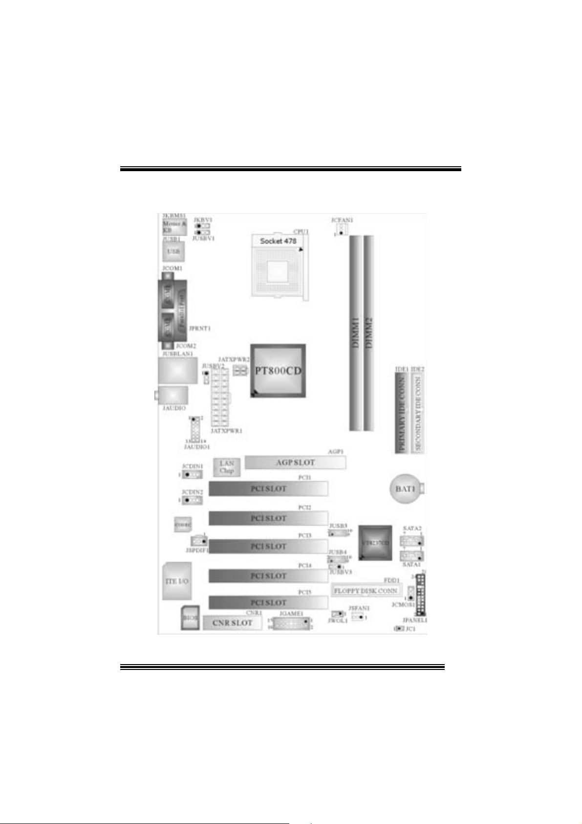
Layo ut of P4V TB (only for version 1. x)
※NOTE: ●represent s the f irst pin.
3
Page 4
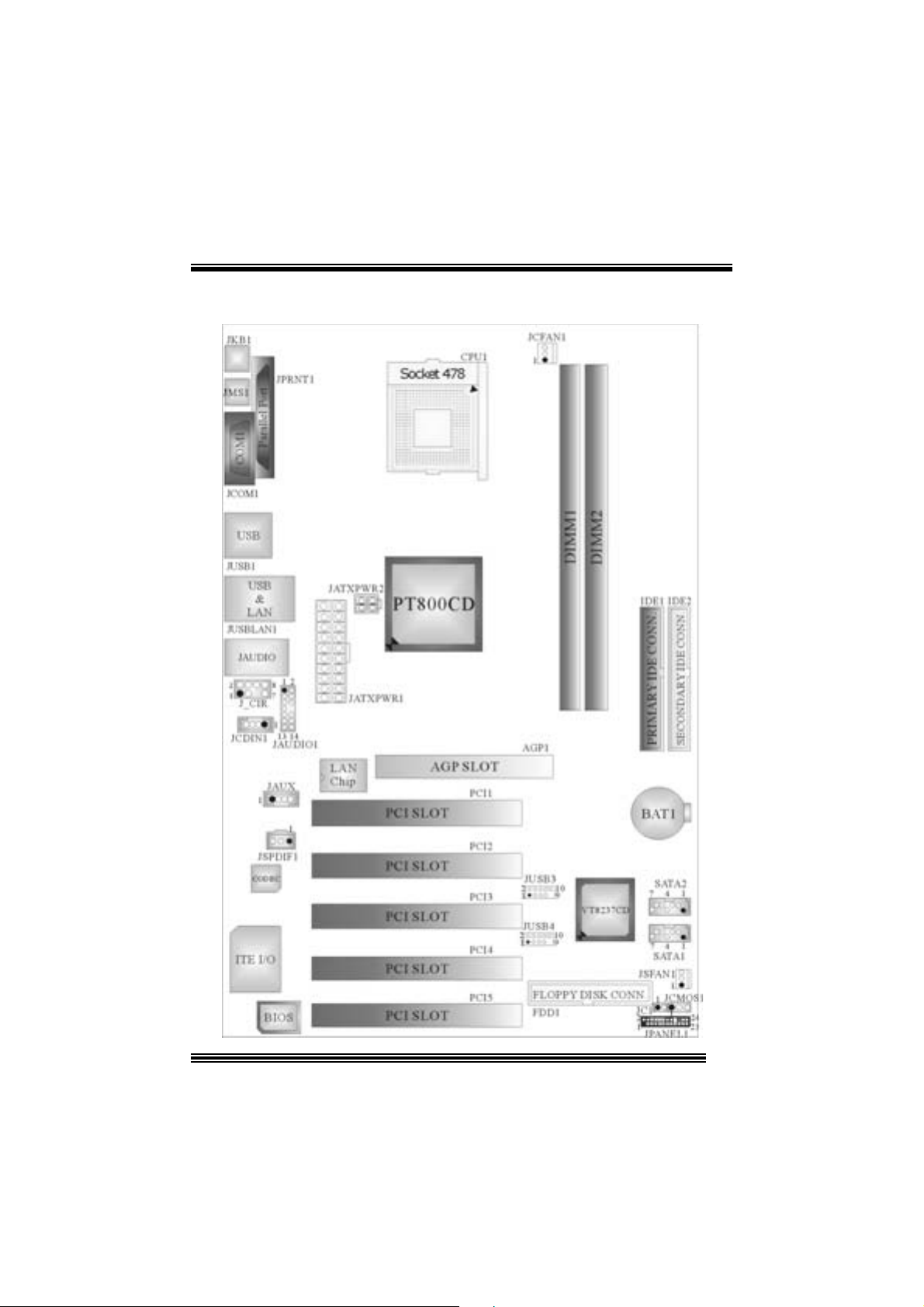
Layo ut of P4V TB (only for version 7. x)
4
Page 5

English
1. P4VTB Feat ure s
A. Har dware
CPU
Provides Socket 478.
Su pports Intel® Pentium® 4 Pr oc es s or.
Su pports Intel® Pentium® 4 Prescott CPU. (only f or vers ions 1.3 and 7.2)
Front Side Bus at 400/533/800 MHz.
Chipset
Nort h Bridge: VIA PT800CD.
Sout h Bridge: VIA VT8237C D.
Main Me m o ry
Support s up t o 2 DDR devices.
Support s 200/ 266/ 333/ 400 MH z D DR devic es.
Maxi mu m memory s iz e o f 2GB.
Super I/O
Chip: ITE IT 8705F.
Low Pin Count I nterfac e.
Prov ides the most commonly used legacy Super I/ O funct ionality.
E nv iro nm ent C ont rol i nit iativ es
- H/W Monitor
- Fan Speed Controller
- I TE's "Smart Guardian" s oft ware utility.
Slots
Fiv e 32-bit PCI bus master slots.
One AGP slot .
One C NR slot. (does not s upport on version 7.x)
On Board IDE
Supports four IDE di s k dri ves.
Supports PIO Mode 4 and Ultra D MA 33/66/ 100/133 Bus Master Mode.
On Bo ard AC’97 Soun d Cod ec (only for ver sion 1.x)
Chip: C MI9739A.
Compliant with AC ’97 s pec ific ation.
AC ’97 2. 2 int erface.
Support s 6 channels.
5
Page 6

On Bo ard AC’97 Soun d Cod ec (only for ver sion 7.x)
Chip: C MI9761A.
Compliant with AC ’97 s pec ific ation.
AC ’97 2. 2 int erface.
Support s 6 channels.
Support s stereo m icrophone.
On Board Peripherals
a. R e ar si de
2 s erial port s. (1 serial port only support on version 7.x)
1 parallel port. (SPP/EPP/ ECP mode)
Audio ports in v ert ical posit ion.
1 LAN port.
PS/2 mouse and PS/2 keyboard.
4 USB2.0 ports.
b. F ront Si d e
1 floppy port supports 2 F DDs wit h 360K, 720K, 1.2M, 1.44M and 2. 88Mby t es.
4 USB2.0 port s.
Dimensions
ATX Form Factor: 20. 5 X 30.5cm . (W X L) (only for v ersion 1.x )
ATX Form Factor: 20. 5 X 29.5cm . (W X L) (only for v ersion 7.x )
B. BIOS & Software
BIOS
Award legal Bios .
APM1.2.
ACPI.
USB Function.
Software
S uppor ts Warpspe ederTM, 9t h Tou c hTM, F LASH ER™and WinF lasher
Off ers the highest perf orm ance for Windows 98 SE, W indows 2000, Windows Me,
Windows XP, SC O UNIX etc.
TM
.
2. Package co ntents
HDD Ca b le X1
FDD Cable X1
User’s Manual X1
USB Cable X1 (optional)
Rear I/ O Panel for ATX C as e X1 (optional)
Fully Setup Driver CD X1
St udioF un! Application C D X1 (opt ional)
6
Page 7
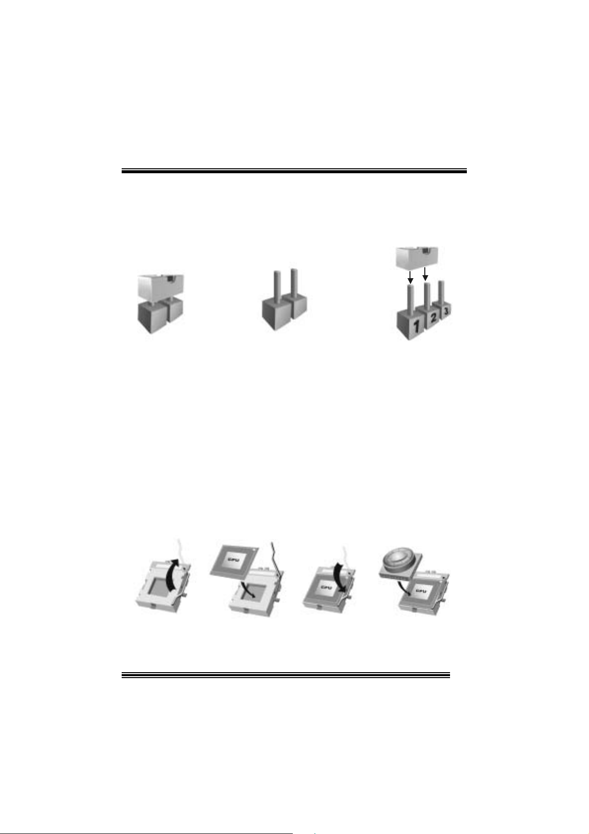
3. How to setup Jumper
The illustrat ion shows how jum pers ar e set up. W hen the Jumper c ap is place d on pins, t he
jumper is “close”. If no jumper cap is placed on the pins, the jumper is ”open”. The
illust rat ion sh ows a 3-pin jumper whos e pin 1and 2 are “close” when jumper c ap is placed
on thes e 2 pins .
Jumper close Jumper open Pin 1-2 close
4. CPU Ins t allation
Step1: Pull the lever sideways away from the soc k et and then raise the lever up to a
90 -degree angl e.
Step2: Look for the white dot/cut edge. The whit e dot/cut edge should point t owards the
lev er pivot. The C PU will fit only in the correct orient ation.
Step3: Hold the CPU down fir ml y, and then close the lever.
Step4: Put t he C PU f an on t he C PU and buck le it. C onnec t the C PU f an power cable to
the JCFAN1. This completes the installation.
Step1 Step2 Step3 Step4
7
Page 8
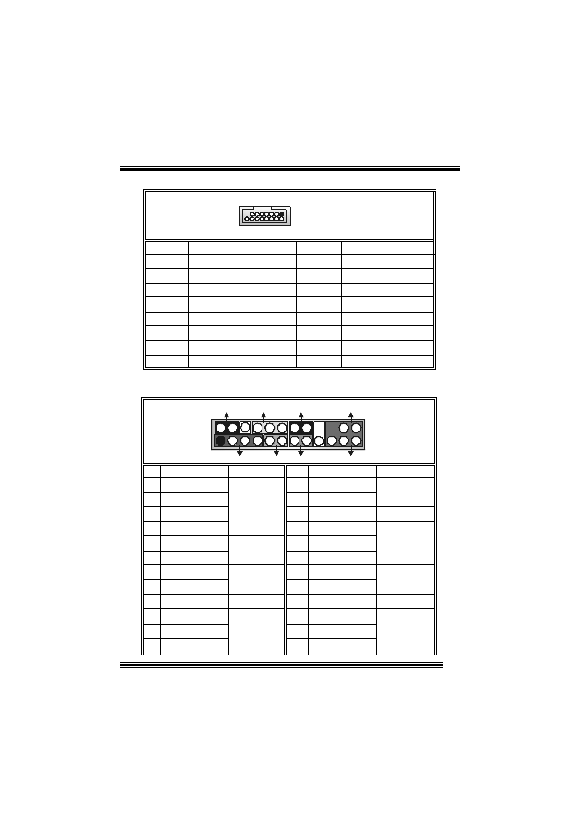
CPU Fan Headers: JCFAN1
3
1
JCFAN1
Pin No . A ssi gnme nt
1
2
3
FAN rpm Ra te Sense
Ground
+12V
S ystem Fan Headers: JSFAN1
Pin No . A ssi gnme nt
13
JSFAN1
1
2
3
FAN rpm Ra te Sense
Ground
+12V
5. DDR DI MM Modu les : DIMM1/ DIMM2
DR AM Access Time: 2.5V Un buff ered DDR 200/ 266/ 333/ 400 MHz Type requ i red.
DRAM Type: 64MB/ 128MB/ 256MB/ 512MB/ 1GB DIMM Module (184 pin)
Total Memory Size wi th Un bu ffere d DIMM s
DIMM S ocket
Location
DIMM1 64MB/128MB/256MB/512MB/1GB
DIMM2 64MB/128MB/256MB/512MB/1GB
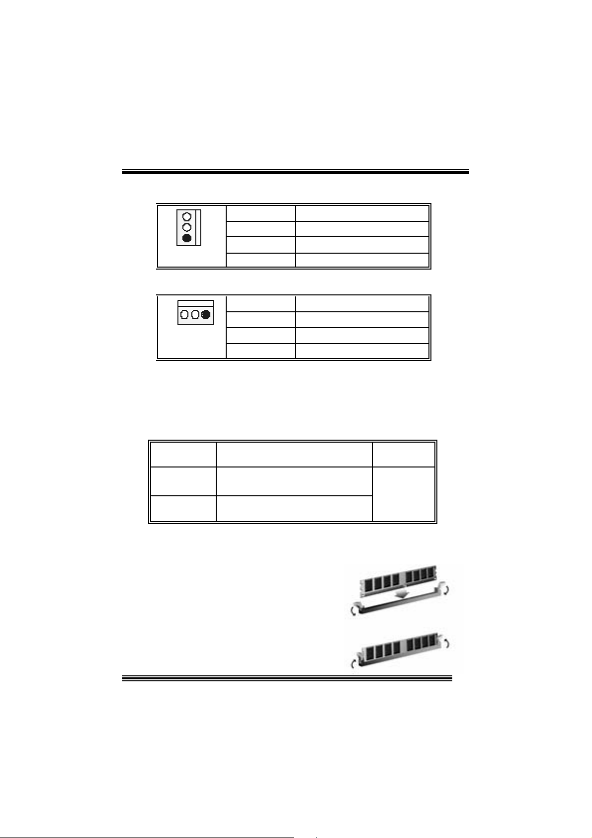
Installing DDR Module
1. Unlock a DIMM slot by pressing the
retaining clips outward. Align a D IMM to the
slot in the way that the notch of the DIMM
matches the break of the slot.
2. Insert the DIMM f irmly and vertically into
the s lot unt il th e retain ing c lip s nap back in
place and the DI MM is properly s eated.
DDR Mod u l e To tal Memory
Size (MB)
*1
*1
***On ly for refer en ce***
Max is
2GB
8
Page 9

6. Jumpers, Headers , Connectors & Slots
(1) Floppy Disk Connector: FDD1
The mot herboard provides a standard f loppy disk connect or that supports 360K,
720K, 1.2M, 1.44M and 2.88M floppy disk types. This connector supports the
prov ided f loppy drive ribbon cables.
(2) Hard Dis k Connectors: IDE1/ IDE2
The motherboard has a 32-bit Enhanced PCI IDE Controller that provides PIO
Mode 0~4, Bus Master, and U ltra D MA 33/ 66/ 100/ 133 f unct ionality. It has two
HDD connec t ors IDE1 (primary) and IDE2 (s econdary ).
The ID E c onnectors can c onnec t a mast er and a slav e drive, so you c an connect
up to four hard disk drives . The first hard drive should alway s be c onnect ed to
IDE1.
(3) Peripheral Component Interconnect Slo ts: PCI 1- 5
This m ot herboard is equipped wit h 5 standard PCI slots. PCI stands f or Peripheral
Component I nterconnec t, and it is a bus standard f or expansion cards. This PCI
slot is designated as 32 bits.
(4) Accelerated Graphics Port Slo t: AGP1
Your monitor will attach directly to that video card. This motherboard supports
video cards f or PCI s lots, but it is als o equipped with an Acc elerated Graphics Port
(AGP). An AGP card will take adv antage of AGP tec hnology f or improv ed v ideo
efficiency and perform ance, es pecially with 3D graphics.
(5) Communicati on Network Riser Slot: CNR1 (does not
support on ver sion 7. x)
The CNR specification is an open I ndust ry St andard Architecture, and it defines a
ha rdw ar e scalable r iser card inter fa ce, which support s modem only.
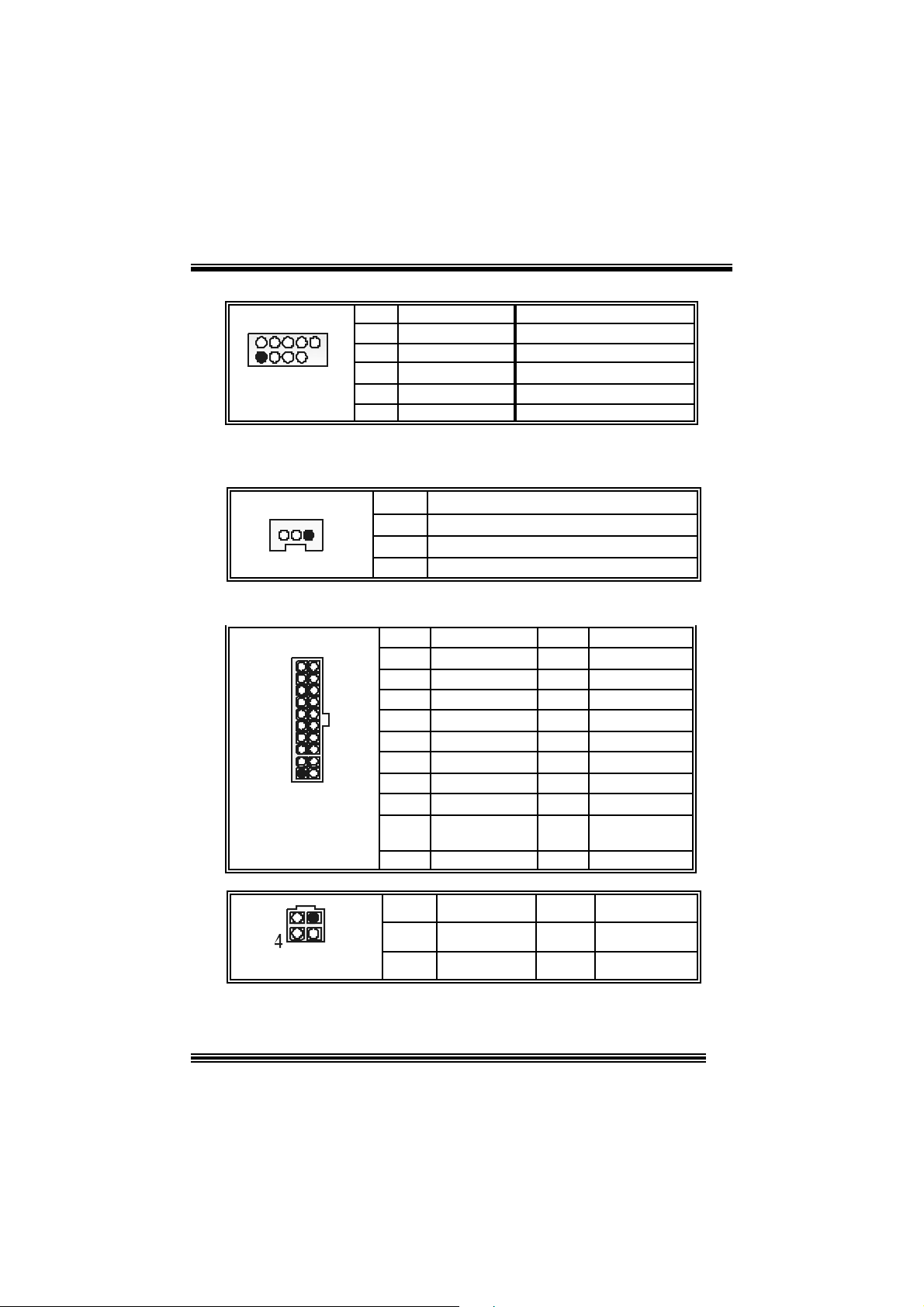
(6) Serial ATA Connector: SATA1/ SATA2
The mot herboard has a PCI to SATA C ontroller with 2 channels SATA interface, it
satisfies the SATA 1.0 spec and can transfer data wit h 1.5GH z s peed.
1234567
SATA1/ SATA2
Pin Assignment Pin Assignment
1
3
5
7
Ground
TXRX-
Ground
2
4
6
TX+
Ground
RX+
9
Page 10
X
(7) Game Header: JGAME1 (does not su pport on versi on 7.x)
15
Pin Assign m ent Pin Assignment
1
3
5
7
9
11
13
15
Joy stick B Butt on 1
Joy stick B C oordinate X
Joy stick B C oordinate Y
Joy stick B Butt on 2
+5V
MIDI Output
MIDI Input
NA
1
216
JGAME1
2
4
6
8
10
12
14
16
Joystick A Button 1
Joy st ick A Coordinate
Joy st ick A Coordinate Y
Joystick A Button 2
+5V
Ground
Ground
+5V
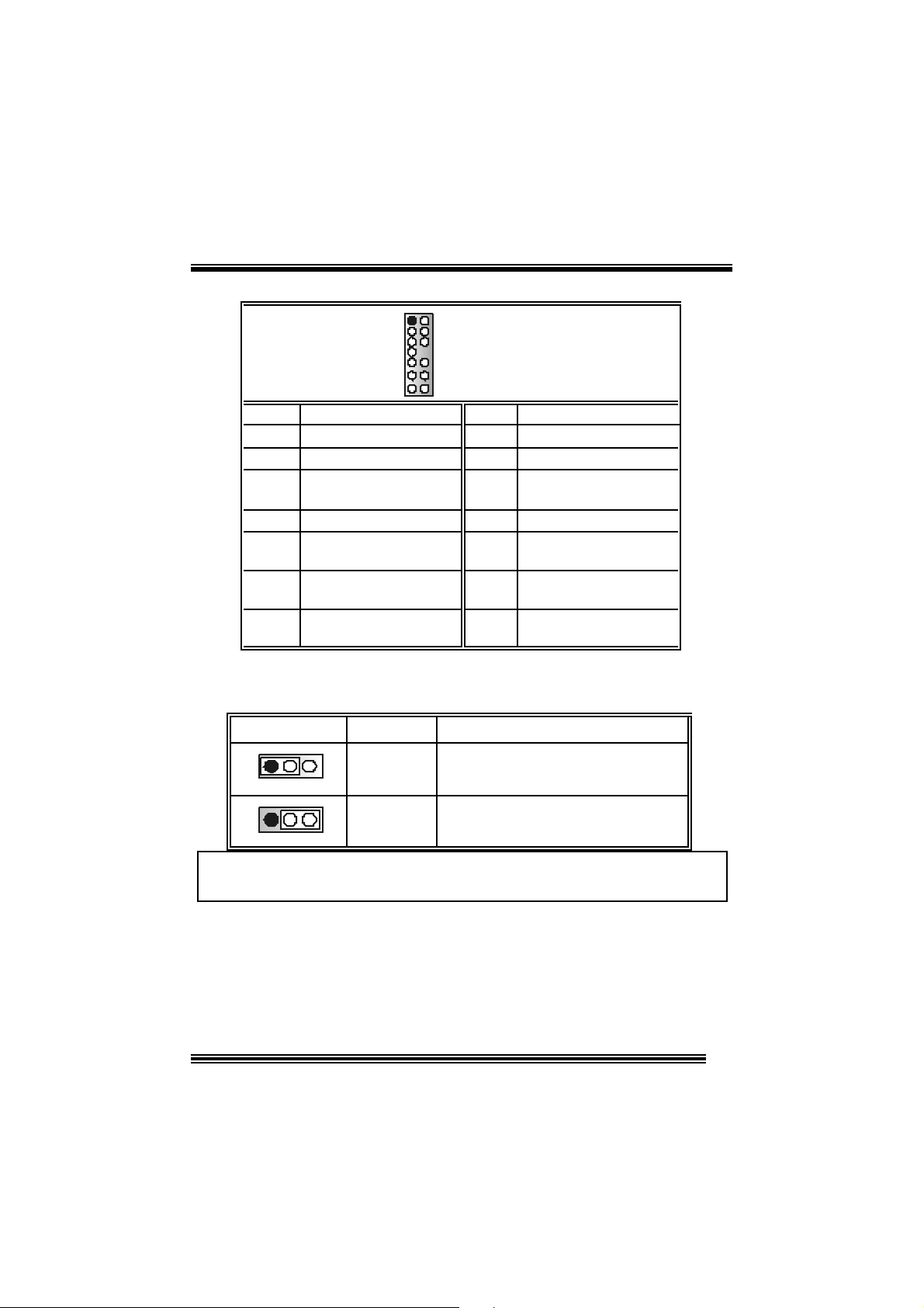
(8) Front Panel Connector: JPANEL1
SLP
JPANEL1
Pin Assignment Function Pin Assignment Function
1 +5V 2 Sleep C ont rol
3 NA 4 Ground
5 NA 6 NA NA
7 Speaker
9 HD D LED (+ ) 10 Power LED (+)
11 H DD LED (-)
13 Ground 14 Power Button
15 Reset Control
17 NA 18 KEY
19 NA 20 KEY
21 +5V 22 Ground
23 IRTX
2
123
PWR_LED
(+) (-)(+)
SPK
Connector
Hard Dr ive
Connector
(+) (-)
HLED
RST
Speaker
8 Power LED (+)
LED
Reset
Button 16 Ground
IrDA
12 Power LED (-)
24 IRR X
IRON/ OFF
IR
24
Sleep
Button
POWER
LED
Power-on
Button
IrDA
Connector
10
Page 11
(9) Front USB Header: JUSB3/ JUSB4
2
1
JUSB3/4
Pin Assignment Pin Assignment
10
1
3 USBN- 4 USBN-
9
5
7
9
+5V
USB+
Ground
KEY
2
6
8
10
+5V
USBP+
Ground
NA
(10) Wake On LAN Header: JWOL1 (does not su pport on
version 7.x)
JWOL1
1
Pin Assignment
1 +5V Standby
2
3 Wak e up
Ground
(11) Power Connecto rs: JATXPWR1/ JAT XPWR2
PIN Assignment PIN Assignment
1 +3.3V 11 +3.3V
2 +3.3V 12 -12V
3 Ground 13 Ground
4 +5V 14 PS_ON
5 Ground 15 Ground
6 +5V 16 Ground
7 Ground 17 Ground
8 PW_OK 18 -5V
9 Standby Voltage
10 +12V 20 +5V
PIN Assignment PIN Assignment
1
2
+5V
+12V
+12V
19 +5V
3
4
10
JATXPWR1
JATXPWR2
20
1
11
12
3
Ground
Ground
11
Page 12
(12) Front Panel Audio Heade r: JAUDIO1
12
13 14
Pin Assignment Pin Assign m ent
1
3 Mic Power/ Bass 4 Audio Power
5
7
9
11
13
Mic I n / C e nter
Right Line Out/ Speaker
Ou t Ri ght
Reserved
Left Line Out/ Speaker
Out Left
Right Line I n/ Rear
Speak er R ight
Left Line In / Rear Speaker
Left
JAUDIO1
2
Right Line Out/ Speaker
6
8
10
12
Left Line In/ Rear Speak er
14
Ground
Ou t Ri ght
Key
Left Line Out/ Speaker
Out Left
Right Line I n/ Rear
Speak er R ight
Left
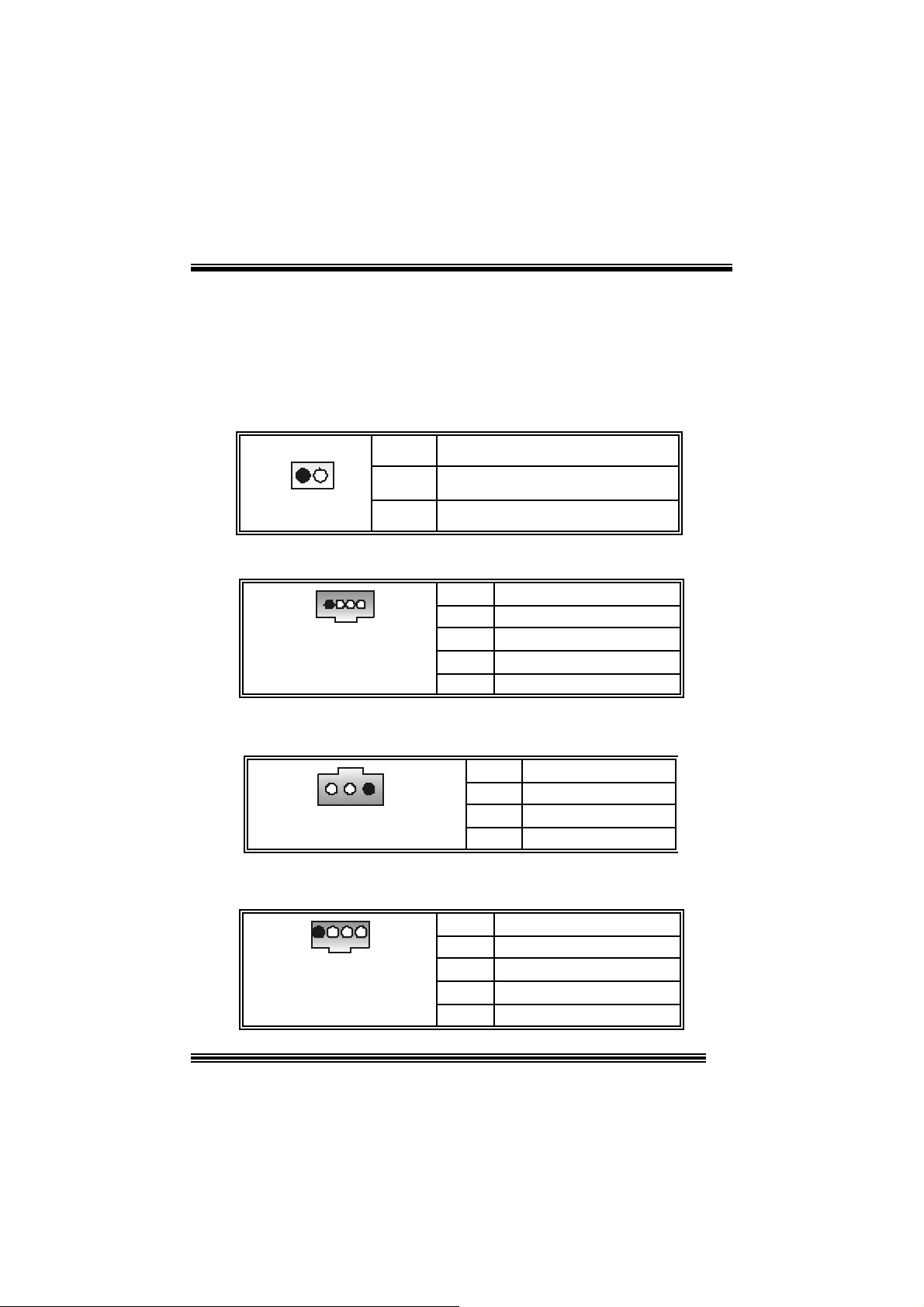
(13) Power Sou rce Selection for Ke ybo ard and Mouse: JKBV1
(does not support on version 7.x)
JKBV1 Assignment
1 3
Pin 1-2 c los e
1 3
Pin 2-3 c los e
+5V
+5V Standby
Voltage
+5V for ke yboar d and mo use
PS/ 2 Mouse and PS/ 2 Key board are
powered with +5V standby v oltage
No t e: In o rde r t o su ppo rt th i s f un cti o n “Pow e r-o n sy ste m vi a ke yb oard and
mouse”, “JKBV1” jumper cap shoul d be placed on pi n 2-3.
Description
12
Page 13
p
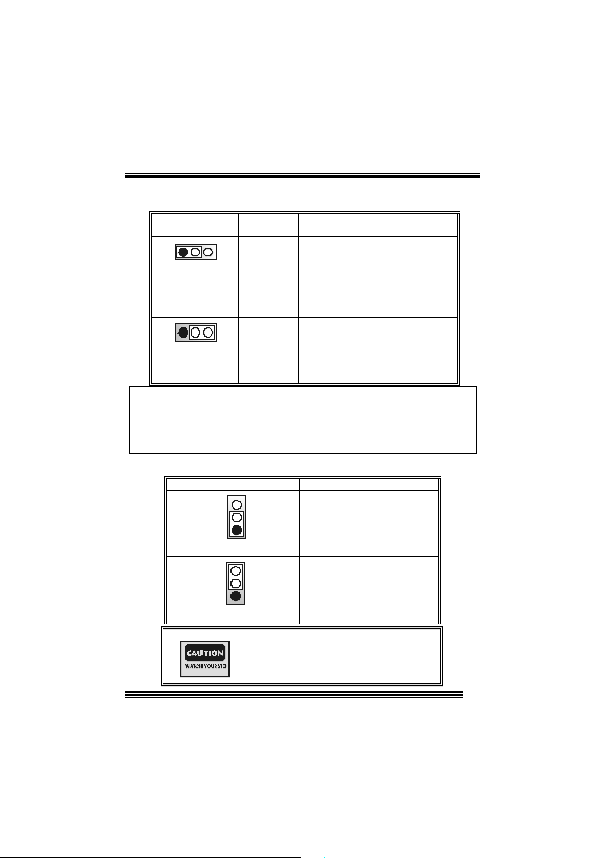
(14) Power Source Selection for USB: JUSBV1/ JUSBV2/
JUSBV3 (does not support on versio n 7.x)
JUSBV1/JUSBV2/
JUSBV3
1 3
Pin 1-2 c lose
1 3
Pin 2-3 c lose
Assignment Description
JU SBV1: 5V for USB locat ed at the
JU S B 1 connector p o rt
JU SBV2: 5V for USB locat ed at the
JU SBLAN1 connec t or port
JU SBV3: 5V for USB locat ed at the
JUSB3/4 connector ports
JU SBV1: JUSB1 port powered with
standby v olt age of 5V
JUSBV2: JUSBLAN1 port powered with
standby v olt age of 5V
JU SBV3: JUSB3/4 port powered with
standby v olt age of 5V
+5V Standby
+5 V
Voltage
Note: 1. In order to support this function “Power-on system vi a USB d evice ”,
“JUSBV1/ JUSBV2/ JUSBV3” jumper cap should be placed on pin 2-3
respectivel y.
2. If you are under S3 mode, we recommend you to select +5V
S tandby Voltage.
(15) Clear CMOS Jumper: JCMOS1
JCMOS1 Assignment
3
1
Pin 1-2 C lose
3
1
Pin 2-3 C lose
Norm al Operation (def ault)
Clear CMOS Data
The follo wing procedu res a re for r esetting the
BIOS
asswor d . It is i mportant to follow these
ins tr u ct ions c lose ly.
13
Page 14
※ Clear CMOS Procedures :
1. R emov e AC power line.
2. Set the jumper to “Pin 2-3 close”.
3. Wait for fi ve se conds .
4. Set the jumper to “Pin 1-2 close”.
5. Power on AC.
6. R eset y our des ired password or c lear the CMOS dat a.
( 16) Case Op en C o nn ecto r : JC1
Assignmen t
Case Open Signal
Ground
1
JC1
Pin
1
2
(17) CD-ROM Audio-In Header: JCDIN1/ (JCDIN2→ only
optional on version 1.x; does not su pport on versi o n 7.x)
1
JCDIN1/ 2
Pin Assignment
1
2
3
4
Left Channel In put
Ground
Ground
Right Channel In put
(18) Di gital Audio Connector: JSPDIF1 (only optional on
ver sion 7.x)
Pin Assignment
1
JSPDIF1
1
2
3 Ground
+5V
SPDIF_OUT
(19) Auxiliary Audio-In Co nnector: JAUX (only opti onal on
ver sion 7.x)
1 4
JAUX
Pin Assignment
1 Left channel AUX_IN
2
3
4
14
CD_Ground
CD_Ground
Righ c hannel AUX_IN
Page 15
p
(20) Consumer Infrare d Header: J_CIR (only opti onal on
version 7.x)
2
1
J_CIR
Pin Assignment Pin Assignment
8
1
7
3
5
7
Ground
CIRRX
Key
SMBDT
2
4
Power-on Butt on
6
8
+5V St andby
SMBCK
CIRTX
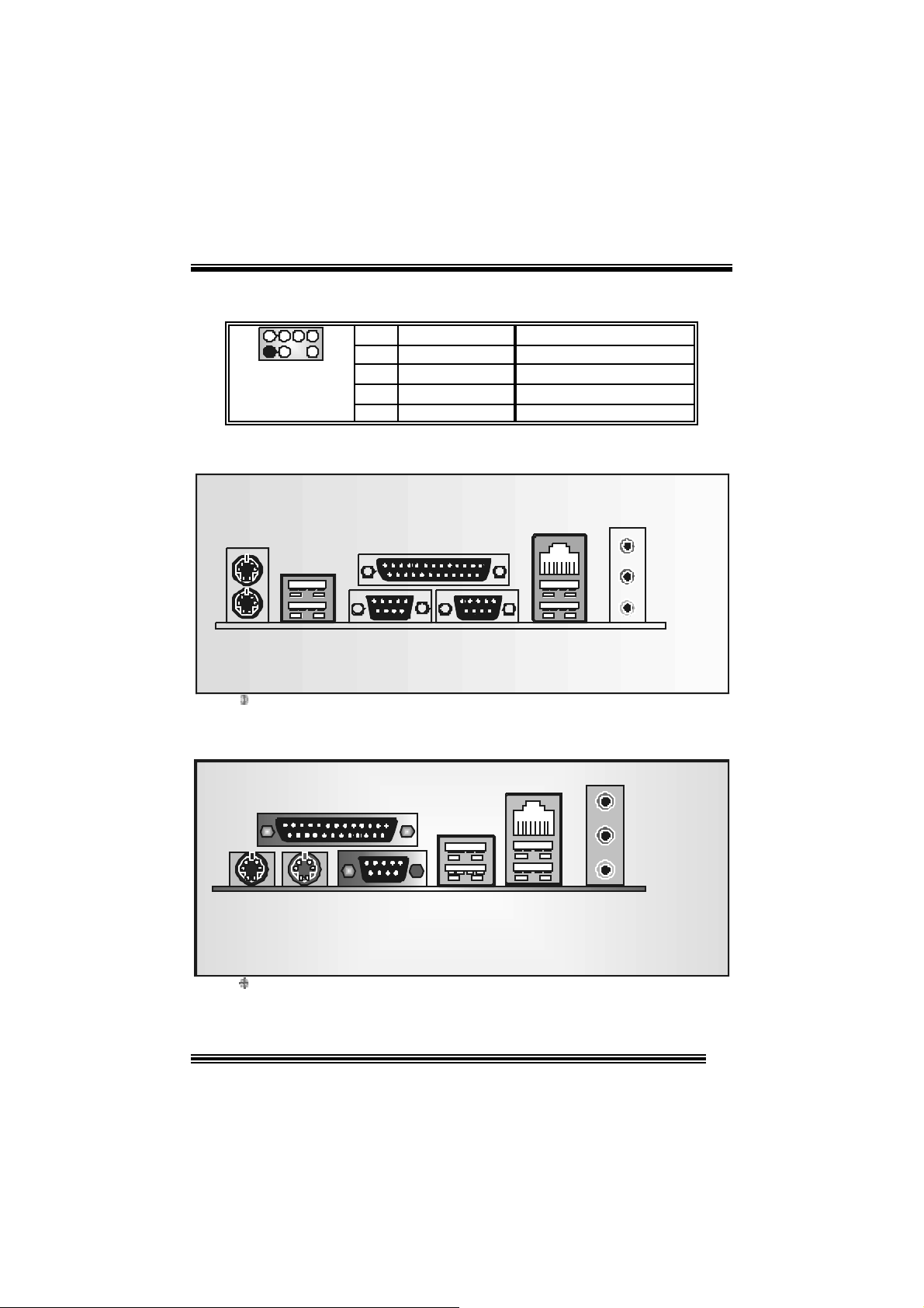
(21) Back Panel Connectors
JKBMS1
PS/2
Mouse
JUSB1
PS/2
Keyboard
only for version 1 . x
USB
Paral le l P ort
PS/2
Mouse
PS/2
Keyboard
JPRNT1
COM1
JCOM1
Parall el
COM2
JCOM2
JUSBLAN2
LAN
USB
COM1 USB
USB
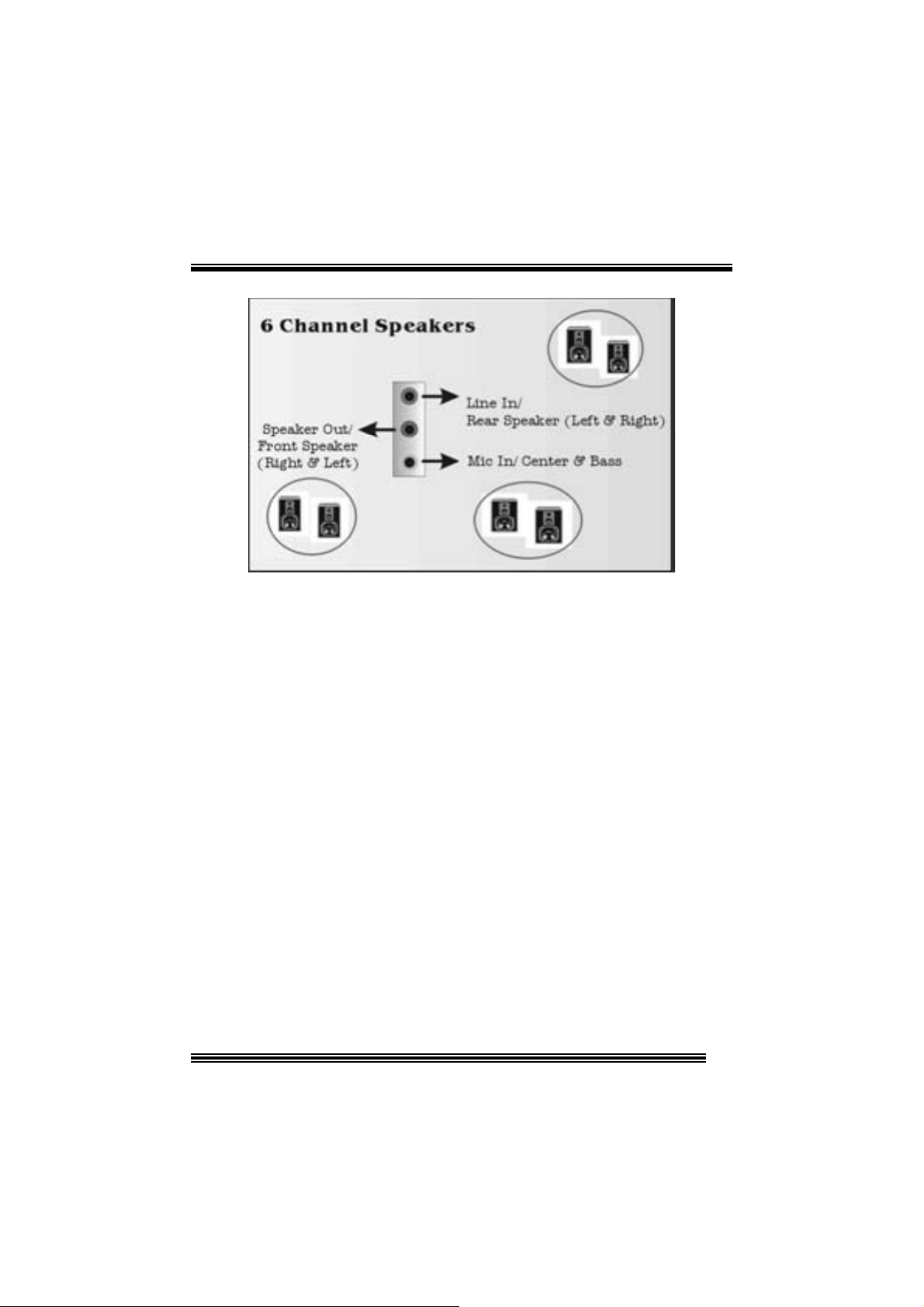
Line In
Speaker Out
MI C In
JAUDIO1
Line In
S
eaker Out
MI C In
only for version 7 . x
15
Page 16
16
Page 17

Français
Car act ér istiq ues de P4VTB
A. Ma tériel
Processeur
Avec socket 478.
Prise en charge du processeur Intel® Pentium® 4.
Prise en charge du processeur Intel® 4 4 78 Pr es c ot t CP U.
Bus f rontal à 400/533/800 MHz.
Jeu de puce s
Nort h Bridge : VIA PT800CD.
Sout h Bridge : VIA VT8237CD.
M é moire prin cipale
Pris e en charge de deux périphériques 2 DDR.
Pris e en charge des périphériques DDR 200/266/ 333/400 MHz (sans ECC).
Taille max imale de la m ém oire :2G o.
Super E/S
Puc e : ITE I T8705.
Fentes
Cinq f entes Bus Mast er PCI à 32 bit s.
Une fen te A GP.
Une fent e CNR. (ne supporte pas en version 7.x)
IDE in tégré
Prise en charge de quatre lecteurs de disque IDE.
Prise en charge de PIO Mode 4 et Ultra DMA 33/66/100/133 Bus Master Mode.
AC’ 97 Sound Codec in tégré (seulement pour version 1.x)
Puc e: C MI9739A.
Conforme aux spécificat ions AC ’97.
Int erf ace AC ’97 2. 2.
Pris e en charge de 6 canaux.
AC’ 97 Sound Codec in tégré (seulement pour version 7.x)
Puc e : CMI 9761A.
Conforme aux spécificat ions AC ’97.
Int erf ace AC ’97 2. 2.
Pris e en charge de 6 canaux.
Pris e en charge de la microphone stereo.
17
Page 18

Périphériq ue s intégrés
a. Côté a rriè re
2 port s série. (1 port série seulement pour v ersion 7.x)
1 port parallèle (m ode SPP/ EPP/EC P)
1 port audio en posit ion v ertic ale.
1 port LAN.
Souris PS/2 et clavier PS/2.
4 ports USB2.0.
b. Côté fron tal
1 port disquette prenant en charge 2 FDD avec 360K, 720K, 1.2M, 1.44M et
2,88Mo.
4 por ts US B2 .0.
Dimensions
Fac t eur de forme ATX : 20, 5 x 30,5c m. (Larg x L)
Fac t eur de forme ATX : 20. 5 x 29.5c m. (Larg x L)
B. BIO S et logiciel
BIOS
Award legal Bios .
APM1.2.
ACPI.
Fonction USB.
Logiciel
Prise en charge de Warps peederTM, 9t h Touc hTM, FLASHER ™ et WinFlasherTM.
Offrant la meilleu re p er forma nce pour Windows 98 SE , Windows 2000, Windows Me ,
Wind ows XP, U N IX seri es etc .
18
Page 19

WarpSpeeder
Introduction
[ W arpSpeeder™ ], a new powerful control utility, features three user-f riendly functions
including Ov erclock Manager, Ov ervolt age Manager, and Hardware Monit or.
With the Over clock Manager, users can easil y adjus t th e freque nc y they prefer or t hey can
get t he best CPU performance wit h jus t one click. The Overv oltage Manager, on the other
hand, helps to power up CPU core voltage and Memory voltage. The cool Hardware
Monitor smartly indicates the tem peratures, voltage and CPU fan s peed as well as the
chips et inf ormat ion. Als o, in the About panel, y ou c an get det ail des c riptions about BI OS
model and chipsets. In addition, the f requency status of C PU, m emory, AGP and PCI
along with t he CPU s peed are synchronically shown on our main panel.
Moreov er, to prot ect users' c om puter syst ems if the s etting is not appropriat e when testing
and results in system f ail or hang, [ WarpSpeeder™ ] technology assures the system
st ability by automat ica lly rebooting the com puter and then restart t o a speed that is either
the original sys t em s peed or a suit able one.
System Requirement
OS Support : Windows 98 SE, W indows Me, Windows 2000, Windows XP
Direc t X: DirectX 8.1 or above. (The Windows XP operating sy s tem inc ludes D irectX 8. 1. If
you us e Windows XP, y ou do not need to inst all DirectX 8.1. )
19
Page 20

Installation
1. Execut e the setup ex ecution f ile, and then the f ollowing dialog will pop up.
Please clic k “Next” butt on and follow t he default proc edure t o install.
2. When you see the following dialog in setup procedure, it means setup is
comple ted . If th e “Launch the War pSpeeder Tray Ut ility” checkbox is checked,
the Tray Icon utility and [WarpSpeeder™] utility will be automatically and
imm ediately launched after you c lic k “Finish” butt on.
20
Page 21

Usage
The foll o wi ng fi gu r es ar e ju st on ly for re f er e nce , t h e s c reen pr inted in th is u s er ma nual w ill
change according to your motherboard on hand.
[W arpSpeeder™] includes 1 t ray ic on and 5 panels:
1. Tray Icon:
Whenev er the Tray Icon ut ility is launched, it will disp lay a little t ray icon on the right side of
Windows Tas k bar.
21
Page 22

This utility is responsible f or convenient ly inv oking [WarpSpeeder™] U tility. You can use
the m ouse by clicking t he lef t button in order t o inv oke [W arpSpeeder™] direct ly from the
litt le t ray icon or you can right-c lick t he litt le t ray icon t o pop up a popup menu as following
figure. The “Launch Utility” item in the popup menu has the sam e function as mouse
left -c lick on tray icon and “Exit” item will c los e Tray I c on utility if select ed.
2. Main Panel
If you click the tra y icon, [ WarpSpeeder™ ] utility will be invoke d. Please refer
do the following figure; the u tility’s fi rst window you will s ee is Main Panel.
Main Panel contains features as follows:
a. Display t he CPU Speed, CPU external c lock, Memory clock, AGP clock, and PC I
cloc k inform at ion.
b. Contains About, Voltage, Overclock, and Hardware Monitor Buttons for invoking
respective panels.
c. With a user-friendly Status Animation, it can represent 3 overclock percentage
stages:
Duck walk ing => overc lock perc entage from 100% ~ 110 %
Duck running => overcloc k perc ent age from 110% ~ 120%
Duck burning => overcloc k perc ent age from 120% ~ abov e
22
Page 23

3. Voltage Panel
Click t he Volt age button in Main Panel, t he but ton will be highlighted and the Volt age
Panel will slide out t o up as the f ollowing f igure.
In this panel, y ou c an decide t o increase CPU c ore v oltage and Memory v oltage or not.
The def ault sett ing is “N o”. If y ou want to get the best perf ormance of ov erclocking, we
recom m end y ou click the option “Y es”.
23
Page 24

4. Overclock Panel
Click t he Overc lock button in Main Panel, the butto n will be high light ed and the Overc lock
Panel will slide out t o left as the following figure.
24
Page 25

Overclock Panel contains these features:
a. “–3MHz button”, “-1MHz but t on”, “+1MHz butt on”, and “+3MHz button”: provide user
the a bility t o do real-t im e ov e rc lock a djustment .
Warning: Manually overclock is potentially dangerous, especially when the
overclocki ng percentage is over 110 %. We strongl y recommend you verify
every speed you overclock by click the Verify button. Or, you can just click
Auto overclock button and l et [ WarpSpeeder™ ] automatically gets the best
result for you.
b. “R ecovery Dialog button”: Pop up the following dialog. Let user select a restoring
way if sy s tem need t o do a f ail-s afe reboot.
25
Page 26

d. “Auto-ov erclock button”: User c an click t his button and [ W arpS peeder™ ] will set
the best and stable perform ance and frequency automatic ally . [ WarpSpeeder™ ]
utility will ex ec ute a se ries of test ing until syst em fail. Then sys t em will do fail-safe
reboot by us ing Watchdog f unct ion. Aft er reboot, the [ WarpSpeeder™ ] utility will
restore to the hardware default setting or load the verified best and stable
frequency a c cording to the Recovery Dialog’s setting.
e. “Verify button”: User can click this button and [ WarpSpeeder™ ] will proceed a
testing for current frequenc y. If the tes ting is ok, t hen the c urrent f requen cy will be
sav ed into sy st em registry . If the testing f ail, syst em will do a fail-safe rebooting.
After reboot, the [ WarpSpeeder™ ] utility will restore to the hardware default
setting or load the verif ied best and stable frequency acc ording to t he Recov ery
Dialog’ s se tting.
Note: Because th e testing programs, in voked in A u to-overclock and Verify,
include DirectD raw, Direc t3D and Dir ect Show tes ts, the DirectX 8. 1 or newer
runtime l ibrary is required. And please make sure your display card’ s color
depth is High color (16 bit) or True color( 24/32 bit ) that is required for
Direct3D rendering.
26
Page 27

5. H ardware Monit or Panel
Click t he Hardware Monitor but t on in Main Panel, t he button will be highlighted and the
Hardware Monitor panel will s lide out to left as the following f igure.
In t his panel, you c an get the real-time stat us inform ation of y our system. The inf ormat ion
will be ref res hed ev ery 1 s econd.
6. About Panel
Click the About button in Main Panel, the butt on will be highlighted and the About Panel
will slide out t o up as t h e following figu re.
In t his panel, you can get model name and detail inf ormat ion in hints of all t he chips et that
are related to overclocking. You can also get the mainboard’s BIOS model and the
Version number of [ WarpSpeeder™ ] utility.
27
Page 28

Note: Because the overclock, overvol tage, and hardware monitor features
are controlled by several separate chipset, [ WarpSpeeder™ ] divide these
features to separate panels. If one chipset is not on board, the correlative
button i n Main panel will be disabled, but will not interfere other panels’
functions. Thi s property can make [ WarpSpeeder™ ] utility more robust.
28
Page 29

Trouble Shooting
g
e
e
r
y
plugg
e
g up
y
pp
a
prog
e
r
e
n
o
o
PROBABLE C AUSE SOLUTION
No pow er to the system at all; power light does n’t
illuminate; fan inside power supply does not turn
on. Indicator li
System inoperative. Keyboard lights are on,
power indic ator lights are lit, and hard dri ve i s
sp in ning.
System does not boot from hard disk drive, but it
can be booted from CD-ROM drive.
System only boots from CD-ROM. Hard disk can
be read and applications can be used but
booting from hard dis k is i mpossible.
ht on keyboard does not turn on.
PROBABLE C AUSE SOLUTION
PROBABLE C AUSE SOLUTION
PROBABLE C AUSE SOLUTION
* Make sure power cable is securely plugged in.
* Repl ac e c abl e.
* Contact tec hnic al s upport.
* Using even pressure on both ends of th
DIM M, press down firmly until the modul
snaps back in places.
* Check cable running from disk to dis k controlle
board. Make sure both ends are securel
ed in; check the drive type in th
standard CMOS setup.
* Backin
important. All hard disks are capable o
breaking down at any time.
* Bac k up data and applications files. Reforma
the hard drive. Re-i nstall a
using backup disks.
the hard drive is extremel
l icat ions and dat
PROBABLE C AUSE SOLUTION
Screen m essage says “Invalid Confi guration” or
“CMOS Failure.”
* Review system’s equipment. Make sure correc
in formation is in setup.
PROBABLE C AUSE SOLUTION
Cannot boot system after installi ng sec ond hard
drive.
* Set master/slave jum p e rs c o rrectly.
* Run SETUP
types. Call drive manufacturers fo
compatibility wi th other dri ves.
ram and select correct driv
PROBABLE C AUSE SOLUTION
Error message reading “SECTOR NOT FOUND”
or other error messages not allowing certai n data
to be retrieved.
* Back up any salvageable data. Then, low-leve
format, partition, and high-level format th
hard drive. Re-install all saved data whe
completed.
PROBABLE C AUSE SOLUTION
Scree is blank. * Check the power connectors to monitor and t
syst em . Make s ure m onitor is co nnec te d t
display card.
29
Page 30

e
n
n
o
PROBABLE C AUSE SOLUTION
Screen goes blank periodically. * Disable screen saver.
PROBABLE C AUSE SOLUTION
Mem ory problem. * Reboot computer. Reinstall mem ory, and mak
sure that al l memory modules are install ed i
correct sockets.
PROBABLE C AUSE SOLUTION
Computer virus. * Use anti-virus programs to detect and clea
viruses.
PROBABLE C AUSE SOLUTION
Keyboard failure. * Reconnect keyborad. Check keys again. If n
improvement, replace keyboard.
PROBABLE C AUSE SOLUTION
No display on screen. * If possible, connect monitor to another system
If no c olor still, replace monitor.
PROBABLE C AUSE SOLUTION
C: drive fail ure. * Check hard drive cable.
PROBABLE C AUSE SOLUTION
Missing operating system on hard drive. * Run setup and sel ect correct drive type.
PROBABLE C AUSE SOLUTION
Certain keys do not function. * Replace keyboard.
PROBABLE C AUSE SOLUTION
Keyboard is locked, no keys function. * Unlock keyboard.
30
Page 31

Dépannage
s
e
u
s
z
n
s
s
p
s
e
s
e
q
a
e
prog
z
e
PROBLÈME SOLUTION
Pas d'alimentation au système. Les voyants
lumineux ne s'allument pas, le ventilateur à
l'intérieur du bloc d'ali mentation ne se met pas
en marche. Le voyant du cl avier ne s'allume pas
PROBLÈME SOLUTION
Le systèm e ne fonc tionne pas. Les voyants du
clavier sont allumés, les voyants de
l'alimentation aussi, le disque dur tourne.
Le système ne se réinitialise pas du disque dur,
réinitialisation possible depuis le lecteur
CD-ROM.
Le système ne se réinitialise que depuis le
CD-ROM. Le disque dur peut être lu et les
applications sont utilisables mais il est
impossible d'effectuer de réinitialisation depuis le
disque dur .
Un mess age s'a ffic he i ndiquant que la
configuration n'est pas valide ou qu'il y a une
panne du CM OS.
Impossible de réinitialiser le système après
l'installation d'un deuxième disque dur.
PROBLÈME SOLUTION
PROBLÈME SOLUTION
PROBLÈME SOLUTION
PROBLÈME SOLUTION
* Assurez-vous que le câble d'alimentati on es
bien branché
* Remplacez le câble
* Contactez le service d'assistance technique.
* En exerçant une pression uniforme sur le
deux extrémités du DIMM, poussez le modul
vers le bas jusqu'à ce qu'il s'enclenche.
* Vérifiez le câble du disque à la carte d
contrôleur de disque. Assurez-vous que le
deux extrémités sont bien branchées ; vérifie
le type de lecteur dans la configuratio
standard de CMOS.
* Il est très important d'effectuer de
sauvegardes du disque dur. Les disques dur
euvent tomber en panne à n'importe que
moment.
* Effectuez une sauvegarde des fichiers de
données et d'application. Reformatez l
disque dur. Ré-installez les applications et le
données sauvegardées sur les disques d
secours.
* Vérifiez l'équipement du système
Assurez-vous
configuration sont c orrectes.
* Réglez les cavaliers maître/esclav
correctement.
* Exécutez le
sélecti onnez les types de lec teur. Contac te
les fabricants pour toute question d
compatibilité avec les autres di sques.
ue les informations de l
ramme SETUP e
31
Page 32

01/16/2004
32
Page 33

P4VTB BIOS Setup
BIOS Setup........................................................................................1
1 Main Menu.....................................................................................................3
2 Standard CMOS Features .............................................................................. 6
3 Advanced BIOS Features...............................................................................9
4 Advanced Chipset Features..........................................................................13
5 Integrated Peripherals ..................................................................................17
6 Power Management Setup ........................................................................... 21
7 PnP/PCI Configurations............................................................................... 25
8 PC Health Status ..........................................................................................28
9 Frequency Control ....................................................................................... 29
i
Page 34

P4VTB BIOS Setup
BIOS Setup
Introduction
T his manua l disc ussed Award™ Setup p rogram bu ilt in to the ROM BIOS. T he Setup
program allows users to modify the basic system configuration. T his special information is
th en st ored in ba tte ry-b acke d RAM so that it r etain s the Set up info rmatio n when the power
is turned off.
T he Award B IO S™ insta lled in you r com puter system’s RO M (R ead Only Me mory ) is a
custom version of an industry standard BIOS. This means that it supports Intel Pentium
processor input/output system. The BIOS provides critical low-level support for standard
devices such as disk drives and serial and parallel ports.
Addin g important has customized the Award BIOS™, but nonstandard, features such as
virus and password protection as well as special support for detailed f ine-tuning of the
chipset controlling the entire system.
The rest of this manual is intended to guide you through the process of configuring your
system using Setup.
Plug a nd Play Support
These AWARD BIOS supports the Plug and Play Version 1.0A specification. ESCD
(Extended System Configuration Data) write is supported.
EPA Green PC Support
This AWARD BIOS supports Version 1.03 of the EPA Green PC specification.
APM Support
These AWARD BIOS supports Version 1.1&1.2 of the Advanced Power Management
(APM) specification. Power management features are implemented via the System
Management Interrupt (SMI). Sleep and Suspend power mana gement modes are supported.
This AWARD BIOS can manage power to the hard disk drives and video monitors .
ACPI Support
Award ACPI BIOS support Version 1.0 of Advanced Configuration and Power interface
specification (ACPI). It provides ASL code for power management and device
configuration capabilities as defined in the ACPI specification, developed by Microsoft,
Intel and Toshiba.
®
4
1
Page 35

P4VTB BIOS Setup
PCI Bus Suppo rt
This AW ARD BIOS also supports Version 2.1 of the Intel PCI (Peripheral Component
Interconnect) local bus specificat ion.
DRAM Support
DDR DRAM (Double Data Rate Synchronous DRAM) are supported.
Suppo rted CP Us
This AWARD BIOS supports the Intel Pentium
Us i ng Se t u p
In general, you use the arrow keys to highlight items, press <Enter> to select, use the
<PgUp> and <PgDn> keys to change entries, press <F1> for help and press <Esc> to quit.
The following tab le provides more detail about how to navigate in the Setup program by
using the keyboard.
Keystroke Function
Up arro w Move to p revious item
Down arrow Move to next item
Left arrow Move to the item on the left (menu bar)
Right arrow Move to the item on the right (menu bar)
Move E nter Move to the i tem you desired
PgUp key Increase the numeric value or make changes
PgDn key Decrease the numeric value or make cha nges
+ Key Increase the numeric value or make changes
- Key Decrease the numeric value or make cha nges
Esc key Main Menu – Quit and not save changes into CMOS
F1 key Genera l he lp o n Set up na vigatio n ke ys
F5 key Load previous values fro m CMOS
F7 key Load the optimized defaults
F10 key Save all the CMOS changes a nd exit
®
4 CPU.
Status Page Setup Menu a nd Option Page Setup Menu – Exit
Current page and return to Mai n Menu
2
Page 36

P4VTB BIOS Setup
1 Main Menu
Once you enter Award BIOS™ CMOS Setup Utility, the Main Menu will appear on the
screen. The Main Menu allows you to select from several setup functions. Use the arrow
keys to select among the items and press <Enter> to accept and enter the sub-menu.
0
WARNING
The information about BIOS defaults on manual (Figu re
1,2,3,4,5,6,7,8,9) is just for reference, please refer to the BIOS
installed on board, for update information.
Figure 1. Main Menu
Standard CM OS Features
This submenu contains industry standard configurable options.
Advance d BIOS Features
This submenu allows you to configure enhanced features of the BIOS.
Advanced Chipset Features
This submenu allows you to configure special chipset features.
3
Page 37

P4VTB BIOS Setup
Integrated Peripherals
This submenu allows you to configure certain IDE hard drive options and Programmed
Input/ Output features.
Power Management Setup
This submenu allows you to configure the power management features.
PnP/PCI Configurations
This submenu allows you to configure certain “Plug and Play” and PCI options.
PC Health Status
This submenu allows you to monitor the hardware of your system.
Fre que ncy Contro l
This submenu allows you to change CPU Vcore Voltage and CPU/PCI clock. ( Howev er,
this function is strongly recommended not to use. Not properly change the voltage
and clock may cause CPU or M/B damage!)
Lo a d Op ti mize d De fa ul ts
This selection allows you to reload the BIOS when the system is having problems
particularly w ith the boot sequence. These configurations are factory settings optimized
for this system. A confirmation message will be displayed before defaults are set.
Set Supervisor Password
Setting the supervisor password will prohibit everyone except the supervisor from making
changes using the CMOS Setup Utility. You will be prompted with to enter a password.
Set User Password
If the Supervisor Password is not set, then the User P assword will function in the same way
as the Supe rvisor P asswor d. If th e Supervis or Pas swor d is set and the User Pa ssword is
set, the “User” will only be able to view configurat ions but will not be able to change them.
4
Page 38

P4VTB BIOS Setup
Save & Exit Setup
Save all configuration changes to CMOS(memory) and exit setup. Confirmation message
will be displayed before proceedin g.
Exit Without Saving
Abandon all changes made during the current session and exit setup. Confirmation message
will be displayed before proceedin g.
Upgrade BIOS
This submenu allows you to upgrade bios.
5
Page 39

P4VTB BIOS Setup
2 Standard CMOS Features
The items in Standard CMOS Setup Menu are divided into 10 categories. Each category
includes no, one or more than one setup items. Use the arrow keys to highlight the item and
then use the<PgUp> or <PgDn> keys to select the value you want in each item.
Figure 2. Standard CMOS Setup
6
Page 40

P4VTB BIOS Setup
Main Menu Selec tions
This table shows the selections that you can make on the Main Menu.
Item Options Description
Date mm : dd : yy Set the system date. Note
Time hh : mm : ss Set the system internal
IDE Primary Master Options are in its sub
menu.
IDE Primary Slave Options are in its sub
menu.
IDE Secondary Master Options are in its su b
menu.
IDE Secondary Slave Options are in its sub
menu.
Drive A
Drive B
Video EGA/VG A
360K, 5.25 in
1.2M, 5.25 in
720K, 3.5 in
1.44M, 3.5 in
2.88M, 3.5 in
None
CGA 40
CGA 80
MONO
that the ‘Day’ automatically
changes when you set the
date.
clock.
Press <Enter> to enter the
sub menu of detailed
options
Press <Enter> to enter the
sub menu of detailed
options.
Press <Enter> to enter the
sub menu of detailed
options.
Press <Enter> to enter the
sub menu of detailed
options.
Selec t the type of floppy
disk drive installed in your
system.
Select the default video
device.
7
Page 41

P4VTB BIOS Setup
Item Options Description
Halt On All Errors
No Errors
All, but Keyboard
All, but Diskette
All, but Disk/ Key
Base Memory N/A Displays the amount of
Extended Memory N/A Displays the amount of
Total Memory N/A Displays the total memory
Select the situation in which
you want th e BIOS to st op
the POST process and
notify you.
conventional memory
detected during boot up.
extended memory detected
during boot up.
available in the system.
8
Page 42

P4VTB BIOS Setup
3 Advanced BIOS Features
Figure 3. Adva nce d BIOS Se tup
Boot Seq & Floppy Setup
First /Seco nd/Third/ Boo t Other De vice
These BIOS attempts to load the operating system from the devices in the sequence
selected in these items.
The Choices: Floppy, LS120, HDD-0, SCSI, CDROM, HDD-1, HDD-2, HDD-3, ZIP100,
USB-FDD, USB-CDROM, USB-HDD, LAN, Enabled, Disabled.
Swap Floppy Drive
For systems with two floppy drives, this option allows you to swap logica l drive
assignments.
The Choices: Ena bled , Dis abl ed (default).
Boot Up Floppy Seek
Enabling th is option w ill test the floppy drives to determine if they have 40 or 80 tracks.
Disabling this option reduces the time it takes to boot-up.
The Choices: Disabled (de fault), en abled.
Cache Setup
CPU L1 & L2 Cache
Dependin g on the CP U/chipset in use, you may be able to increase memory access time
9
Page 43

P4VTB BIOS Setup
with this option.
Enabled (default) Enable cache.
Disabled Disable cache.
CPU L3 Cache
This item allows you to enable or disab le the CP U L3 Cache.
The Choices: Enabled (default), Disabled.
CPU L2 Cache ECC Checking
T his ite m allows you to enab le/dis ab le CP U L2 Ca che ECC Ch eckin g.
The Cho ices: Enabled (default), Disabled.
Shadow Setup
Video BIOS Shadow
Determines whether video BIOS will be copied to RAM for faster execution.
Enabled (default) Optional ROM is enabled.
Disabled Optional ROM is disabled.
CPU Feature
Thermal Management
This option allows you to select the way to control the “Thermal Management.”
The Choices: Thermal Monitor 1 ( Defa ult), Ther mal Mo nitor 2.
TM2 B us Ra tio
This option represents the frequency (bus ratio of the throttled performance state
that will be in itiated when the on-diesensor goes from not hot to hot.)
Min= 0
Max= 255
Key in a DEC number=
The Choices: 0 X (Def ault)
TM2 B us VID
This option represents the voltage of the throttled performance state that will be
initiated when the on-diesensor goes from not hot to hot.
The Choices: 0.8375V (Default), 0.8375-1.6000.
Limit CPUID MaxVal
Set Lim it CP UID MaxVal to 3, it should be “Disabled” for WinXP .
The Choices: Disabled (Default), Enabled.
Virus Warning
This option allows you to choose the VIRUS Warning feature that is used to protect the
IDE Hard Disk boot sector. If this function is enabled and an attempt is made to write to the
boot sector, BIOS will disp lay a warning message on the screen and sound an alarm beep.
10
Page 44

P4VTB BIOS Setup
Disabled (default) Virus protection is disabled.
Enabled Virus protection is activated.
Hyper-Threading Technology
This option allows you to enable or disabled CPU Hyper-Threading.
The Cho ices: Enabled (Default), Disabled.
Quick Power On Self Test
Enabling this option will cause an abridged version of the Power On Self-Test (POST) to
execute after you power up the computer.
Disabled Normal POST.
Enabled (default) Enable quick POST.
Boot Up NumLock Status
Selects the NumLock. State after power on.
On (default) Numpad is number keys.
Off Numpad is arrow keys.
Typematic Rate Se tting
When a key is held down, the keystroke will repeat at a rate determined by the keyboard
controller. When enabled, the typematic rate and typematic delay can be configured.
The Cho ices: Disabled (default), Enabled.
Typematic Rate (Chars/Sec)
Sets the rate at which a keystroke is repeated when you hold the key down.
The Choices: 6 (default), 8, 10, 12, 15, 20, 24, 30.
Typematic Delay (Msec)
Sets the delay time after the key is held down before it begins to repeat the keystroke.
The Choices: 250 (default), 500,750,1000.
Security Option
This option will enable only individuals w ith passwords to bring the system online and/or
to use the CMOS Setup Utility.
System: A password is required for the system to boot and is also required to access the
Setup Utility.
Setup (default): A password is required to access the Setup Utility only.
This will only apply i f passwords are set from the Setup main menu.
APIC Mode
Selecting Enabled enab les APIC device mode reporting from the BIOS to the operating
system.
The Ch o i ces : En a b led (default), Disabled.
11
Page 45

P4VTB BIOS Setup
MPS Version Control Fo r OS
The BIOS supports version 1.1 and 1.4 of the Intel multiprocessor specification.
Select version supported by the operation system running on this computer.
The Ch o i ces : 1 . 4 (default), 1.1.
OS Select For DRAM > 64MB
A choice other than Non-OS2 is only used for OS2 systems with memory exceeding 64MB.
The Ch o i ces : No n-OS2 (default), OS2.
Sum mary Screen Show
This item allows you to enable/disable the summary screen. Summary screen means
system configuration and PCI device listing.
The Cho ices: Enab led, Disabled (default).
12
Page 46

P4VTB BIOS Setup
4 Advanced Chipset Features
This submenu allows you to configure the specific features of the chipset installed on your
system. This chipset manage bus speeds and access to system memory resources, such as
DRAM. It also coordinates communications with the PCI bus. The default settings that came
with your system have been optimized and therefore should not be changed unless you are
suspicious that the settings have been changed incorrectly.
Fig ure 4. Adva nce d Chipse t Setup
DRAM Clock/ Drive Control
To control the Clock. If you high light the literal “Press Enter” next to the “DRAM Clock”
label and then press the enter key, it will take you to a submenu with the following opt ions:
DRAM Clock
This item determines DRAM clock following 100MHz, 133MHz or By SPD.
The Choices: 100MHz, 133MHz, 166MHz, 200MHz, By SPD (default).
DRAM Timing
This item determines DRAM clock/ timing follow SPD or not.
The Choices: Auto By SPD (default), Manual, Turbo, Ultra.
SDRAM CAS Latency
When DRAM is installed, the number of clock cycles of CAS latency depends on
the DRAM timing.
The Choices: 2, 2.5 (default).
13
Page 47

P4VTB BIOS Setup
Ba nk In terl eave
This item allows you to enable or disable the bank interleave feature.
The Choices: Disabled (default).
Precha rge to Active (Trp)
This items allows you to specify the delay from precharge command to activate
command.
The Choices: 4T (default).
AGP & P2P Bridge Co ntrol
If you highlight the literal “Press Enter” next to the “AGP & P 2P Bridge Control” label and
th en pr ess t he ente r key, it w ill tak e you a s ubmenu with t he follow in g options :
Active to Precharge (Tras)
This items allows you to specify the minimum bank active time.
The Choices: 9T (default).
Active to CMD (Trcd)
Use this item to specify the delay from the activation of a bank to the time that a
read or write command is accepted.
The Choices: 5T (default).
DRAM Command Rate
This item controls clock cycle that must occur between the last valid write
operation and the next command.
The Choices: 1T Command, 2T Co mman d (default).
DRAM Burst Len
The Choices: 4 (default), 8.
Write Recovery Time
The Choices: 2T (default), 3T.
tWTR for DDR400 Only
The Choices: 3T (default), 1T.
AG P Apert ure Size
Select the size of the Accelerated Graphics Port (AGP) aperture. The aperture is a
portion of the PCI memory address range dedicated for graphics memory address
space. Host cycles that hit the aperture range are forwarded to the AGP without
any translation.
The Choices: 512M, 256M, 128M, 64M (default), 32M, 16M, 8M, 4M, 1G.
AGP Mode
This item allows you to select the AGP Mode.
The Choices: 4X (default), 8X, 2X, 1X.
14
Page 48

P4VTB BIOS Setup
AGP Driving Control
By choosing “Auto” the system BIOS will the AGP output Buffer Drive strength
P Ctrl by AGP Card. By choosing “Manual”, it allows user to set AGP output
Buffer Drive strength P Ctrl by manual.
The Choices: Auto (default), Manual.
AGP Driving Value
While AGP driv in g control item set to “Manua l”, it al lows use r to s et AGP
dr iv ing.
The Choices: DA (default).
AG P Fast Write
The Choices: Ena bled , Dis abl ed (default).
AGP Master 1 WS Write
When Enabled, writes to the AGP (Accelerated Graphics Port) are executed with
one wait states.
The Choices: Disabled (default), Enabled.
AGP Master 1 WS Read
When Enabled, read to the AGP (Accelerated Graph ics Port) are executed with
one wait states.
The Choices: Disabled, En a bl ed (default).
AGP 3.0 Calibration cycle
T his item allows you to disable or enable the AGP 3..0 Calibration Cycle.
The Cho ices: Enabled (default), Disabled.
CPU & PCI Bus Control
If you highlight the litera l “Press Enter” next to the “CPU & PCI Bus Control” label and
th en pr ess t he ente r key, it w ill tak e you a s ubmenu with t he follow in g options :
PCI Master 0 WS Write
When Enabled, writes to the PCI bus are executed with zero-wait states.
The Cho ices: Enabled (default), Disabled.
PCI Delay Transaction
The chipset has an embedded 32-bit posted write buffer to support delay
transactions cycles. Select Enabled to support compliance with PCI specificat ion
version 2.1.
The Choices: Enabled (default), Disabled.
VLink 8X Support
The Cho ices: Enabled (Default), Disabled.
15
Page 49

P4VTB BIOS Setup
Memory Hole
You can reserve this area of system memory for ISA adapter ROM. When this area is
reserved it cannot be cached. The user information of peripherals that need to use this area
of system memory usually discussed their memory requirements.
The Choices: Disabled (default), 15M-16M.
System BIOS Cacheable
Selecting the “Enabled” option allows caching of the system BIOS ROM at
F0000h-FFFFFh which can improve system performance. However, any programs
writing to this area of memory will cause conflicts and result in system errors.
The Choices: Ena bled , Dis abl ed (default).
Delay Prior to Thermal
Set this item to enable the CPU Thermal function to engage after the specified time.
The Choices: 16Min (d efault) , 4Min, 8M in , 32Min.
16
Page 50

P4VTB BIOS Setup
5 Integrated Peripherals
Figure 5. Integrated Peripherals
VI A O nChip I DE De v ice
If you highlight the literal “Press Enter” next to the “VIA OnChip IDE Device” label and then
press the enter key, it will take you a submenu with the following options:
On-Chip Serial ATA
This item allows you to choose “Disabled” to disabled SATA Controller, “Auto”
auto arrange by bios, “Combined Mode” PATA and SATA are combined with a
maximun of 2 IDE drives in each channels, “Enhanced Mode” enabled SATA and
PATA with a maximun of 6 IDE d rives, “SAT A Only” SAT A is oper at in g in
legacy mode.
The Cho ices: Enabled (default), Disabled.
IDE DMA Transfer Access
The “onboard” IDE drive interface supports IDE DMA read/write function.
The Ch o i ces : En a b led (default), Disabled.
On Chi p IDE Channel 0/1
The motherboard chipset contains a P CI IDE interface with support for
two IDE channels. Select “Enabled” to activate the first and/or second IDE
interface. Select “Disab led” to deactivate an interface if you are goin g to install a
primary and/or secondary add-in IDE interface.
The Ch o i ces : En a b led (default), Disabled.
17
Page 51

P4VTB BIOS Setup
IDE Prefetch Mo de
The “onboard” IDE drive interfaces supports IDE prefetching for faster drive
access. If the interface does not support prefetching. If you install a primary
and/or secondary add-in IDE interface, set this option to “Disabled”.
The Ch o i ces : En a b led (default), Disabled.
Prima ry / Secondary /Master / Slave PIO
The IDE PIO (Programmed Input / Output) fields let you set a PIO
mode (0-4) for each of the IDE devices that the onboard IDE interface
supports. Modes 0 to 4 will increased performance progressive ly. In Auto mode,
the system automatically determines the best mode for each device.
The Cho ices: Auto (default), Mode0, Mode1, Mode2, Mode3, Mode4.
Prima ry / Secondary /Master / Slave UDMA
Ultra DMA/100 functiona lity can be implemented if it is supported by the IDE
hard drives in your system. As well, your operating environment requires a DMA
driver (Windows 95 OSR2 or a third party IDE bus master driver). If your hard
drive and your system software both support Ultra DMA/100, select Auto to
enable BIOS support.
The Cho ices: Auto (default), Disabled.
IDE HDD Block Mode
Bloc k M ode is also ca lled b lock t ransfer, mult ip le comma nds, or m ult ip le se ctor
read/write. If your IDE hard drive supports block mode (most new drives do),
select Enabled for automatic detection of the optima l number of block read/write
per sector where the drive can support.
The Ch o i ces : En a b led (default), Disabled.
VIA OnChip PCI Device
If you highlight the literal “Press Enter” next to the “VIA OnChip PCI Device” label and then
press the enter key, it will take you a submenu with the following options:
VIA-3058 AC97 Audio
This option allows you to control the onboard AC97 audio.
The Cho ices: Auto (default), Disabled.
VIA-3043 OnChip LAN
This option allows you to control the onboard LAN.
The Ch o i ces : En a bled (default), Disabled.
Onboard LAN Boot ROM
Decide whether to invoke the boot ROM of the onboard LAN chip.
The Cho ices: Disabled (default), Enabled.
OnChi p USB Controller
Th is option shou ld be enabled if your syst em has a USB insta lled on the sy stem
18
Page 52

P4VTB BIOS Setup
board. You will need to disable this feature if you add a higher performance
controller.
The Choices: All Enabled (d ef ault) , All Dis ab led
Supe r IO Device
Press Enter to configure the Super I/O Device.
O n bo a rd F D C Co nt ro lle r
Select Enabled if your system has a floppy disk controller (FDC) installed on the
system board and you wish to use it. If install and FDC or the system has no
floppy drive, select Disab led in this field.
The Cho ices: Enabled (default), Disabled.
Onboard Serial Port 1
Select an address and corresponding interrupt for the first and second serial ports.
The Cho ices: 3F8/IRQ4 (default), Disab led, Auto, 2 F8/IRQ3, 3E8/ IRQ4 ,
2E8/IRQ3.
Onboard Serial Port 2
Select an address and corresponding interrupt for the first and second serial ports
The Choices: 2F8 /IR Q3 (default), Disabled, Auto, 3F8/IRQ4 , 3E8/IRQ4,
2E8/IRQ3.
UART Mode Select
This item allows you to determine which Infrared (IR) function of onboard I/O
chip.
The Cho ices: Normal (default), SCR, AS KI R, IrDA.
UR2 Duplex Mode
Select the value required by the IR device connected to the IR port. Full-duplex
mode permits simu ltaneous two-direction transmission. Half-dup lex mode
permits transmission in one direction only at a time.
The Choices: Half (def ault) , Full.
Onboard Parallel Port
This item allows you to determine access onboard parallel port controller with
which I/O Address.
The Cho ices: 378/IRQ7 (default), 278/IRQ5, 3BC/IRQ7, Disabled.
Parallel Port Mode
T he default value is SP P.
The Choices:
SPP (Default) Using Parallel P ort as Standard Printer Port.
EPP Using Parallel Port as Enhanced Parallel Port.
ECP Using Parallel Port as Extended Capabilities Port.
ECP+EPP Using Parallel Port as ECP & EPP mode.
19
Page 53

P4VTB BIOS Setup
ECP Mode Use DMA
Se lect a DM A Ch annel for th e por t.
The Choices: 3 (default), 1.
Init Display First
With systems that have multiple video cards, this option determines whether the primary
display uses a PCI Slot or an AGP Slot.
The Choices: PCI Slot (default), AGP.
20
Page 54

P4VTB BIOS Setup
6 Power Management Setup
The Power Management Setup Menu allows you to configure your system to utilize energy
conservation and power up/power down features.
Figure 6. Power Management Setup
ACPI Function
This item displays the status of the Advanced Configuration and Power Management
(ACPI).
The Choices: En a bl ed (default), Disab led.
Power Management
This category allows you to select the type (or degree) of power saving and is directly
related to the following modes:
1.HDD Power Down.
2.Doze Mode.
3. Susp end M ode.
There are four options of Power Management, three of which have fixed mode settings
Min. Saving
Minimum power management.
Doze Mode = 1 hr.
Standby Mode = 1 hr
Su spend Mode = 1 hr.
HDD Power Down = 15 min
21
Page 55

P4VTB BIOS Setup
Max Saving
Maximum power management only available for sl CP U’s.
Doze Mode = 1 min
Standby Mode = 1 min.
Su spend Mode = 1 min.
HDD Power Down = 1 min.
User Defined (d efault)
Allows you to set each mode individually.
When not disabled, each of the ranges are from 1 min. to 1 hr. except for
HDD Power Down which ranges from 1 min. to 15 min. and disable.
HDD Power Down
When enabled and after the set time of system inactivity , the hard disk drive will be
powered down while all other devices remain active.
The Choices: Disabled (d efault), 1M in, 2Min, 3Min, 4 M in, 5Min, 6Min , 7M in, 8M in,
9Min, 10Min, 11Min, 12Min, 13Min, 14Min, 15Min.
Suspe nd Mode
When enabled and after the set time of system inactivity, all devices except the CPU will be
shut off.
The Choices: Disabled (default), 1Min, 2Min, 4Min, 8Min, 12Min, 20Min, 30Min, 40Min,
1Hour.
Video Off Option
This field determines when to activate the video off feature for monitor power
management.
The Choices: Suspend→Off (default), Always on.
Video Off Method
T his op tion de term ines the mann er in whic h the mo nitor is goes blank.
V/H SYNC+Blank (default)
T his selection will cause the system to turn off the vertical and horizontal
synchronization ports and write blanks to the video buffer.
Blank Screen
This option only writes blanks to the video buffer.
DPMS
Initia l disp lay p ower mana gement signa lin g.
22
Page 56

P4VTB BIOS Setup
MODEM Use IRQ
This determines the IRQ, which can be applied in MODEM use.
The Choices: 3 (de fault)/ 4 / 5 / 7 / 9 / 10 / 11 / NA
Soft-Off by PWR-BTTN
Pressing the power button for more than 4 seconds forces the system to enter the
Soft-Off state when the system has “hung.”
The Choices: De lay 4 Sec , Instant-Off (default).
Ac Loss Auto Restart
This field determines the action the system will automatically take when power is restored
to a system that had lost power previously without any subsequent manual intervention.
There are 3 sources that provide current to the CMOS area that retains these P ower-On
instructions; the motherboard battery (3 V), the P ower Supply (5VSB), and the P ower
Supply (3.3V). While AC is not supplying power, the motherboard uses the motherboard
battery (3V). If AC power is supplied and the Power Supply is not turned on, 5VSB from
the Power Supply is used. When the Power Supply is eventually turned on 3.3V from the
Power Supply will be used.
There are 3 options: “Former-Sts”, “On”, “Off”.
“Off” (default) Means always set CMOS to the “Off” status when AC power is lost.
“On” Means always set CMOS to the “On” status when AC power is lost
“Former-Sts” Means to maintain the last status of the CMOS when AC power is lost.
Fo r exam ple : If s et to “ Former-Sts” and AC power is lost w hen sy stem is live, then a fter
AC power is restored, the system will automatically power on. If AC power is lost when
system is not live, system will remain powered off.
Chassis Open Warning
This item allows you to enable or disable chassis open warnin g beep sound.
The Choices: Disabled (default), Enabled.
IRQ/Event Activity Detect
If you high light the literal “P ress Enter” next to the “IRQ/Event Activity Detect” label and
th en pr ess t he enter key, it w ill tak e you a s ubmenu with t he fo llow in g options :
VGA
When set to On, a ny ev ent occu rr ing at a VGA Port will awak en a system wh ich
has been po were d down.
The Choices: Off (default), On.
LPT & COM
When this o pt ion is set t o On, any event occurring at a COM(serial)/LP T (printer)
port will awaken a system which has been powered down.
The Cho ices: LPT/COM (default), COM, LPT, NONE.
23
Page 57

P4VTB BIOS Setup
HDD & FDD
When this option is set to On, any ev ent occurring on a hard driv e or a floppy
drive will awaken a system which has been powered down.
The Choices: On (default), Off.
PCI Master
When set to On, you need a LAN add-on card which supports the power function.
It should also support the wake-up on LAN jump.
The Choices: Off (default), On.
Po werOn b y PCI Card
When you select Enabled, a PME signal from PCI card returns the system to Full
ON state.
The Choices: Disabled (default), Enabled.
Mo dem Rin g Resume
The Choices: Disabled (Default), Enabled.
RTC Alarm Resume
When “Enabled”, you can set the date and time at which the RTC (real-time clock)
alarm awakens the system from Suspend mode.
The Choices: Ena bled , Dis abl ed (default).
Date (of Month)
Yo u can cho ose which m o nth th e syst em will boot up. T his field is only
configurable when “RT C Resume” is set to “Enabled”.
Resume Time (hh:mm:ss)
You can choose the hour, minute and second the system will boot up. T his fie ld is
only configurable when “RTC Resume” is set to “Enabled”.
IR Qs Activity Mo ni to rin g
Press Enter to access another sub menu used to configure the different wake up
events (i.e. wake on LPT & COMM activity).
Primary INTR On
IRQ3 (COM2) Disabled
IRQ4 (COM1) Enabled
IRQ5 (LPT2) Enabled
IRQ6 (Floppy Disk) Enabled
IRQ7 (LPT1) Enabled
IRQ8 (RTC Alarm) Disabled
IRQ9 (IRQ2 Redir) Disabled
IRQ10 (Reserved) Disabled
IRQ11 (Reserved) Disabled
IRQ12 (PS/2 Mouse) Enabled
IRQ13 (Coprocessor) Enabled
IRQ14 (Hard Disk) Enabled
IRQ15 (Reserved) Disabled
24
Page 58

P4VTB BIOS Setup
7 PnP/PCI Configurations
This section describes configuring the PCI bus system. PCI, or Personal Computer
Interconnect, is a system, which allows I/O devices to operate at speeds nearing the speed
of the CPU itself uses when communicating with its own special components. This section
covers some very technical items and it is strongly recommended that only experienced
users should make any changes to the default settings.
Figure 7. P nP/PCI Configurations
PNP OS Installed
Wh en set to Y ES, BIO S will on ly init ialize the P nP cards used for the boot sequenc e (VGA,
ID E, SCSI). The r est of the ca rds will be init ia lize d by th e PnP operating sys tem like
Windo w™ 95. Whe n set t o N O, BIOS will init ia l ize a ll the P nP cards. For non-P nP
operatin g systems (DOS, Netware™), this option must set to NO.
The Choices: No (default), Yes.
Reset Configuration Da ta
The system BIOS supports the PnP feature which requires the system to record which
resources are assigned and protects resources from conflict. Every peripheral device has a
node, which is called ESCD. This node records which resources are assigned to it. The
system nee ds to record and u pdate ES CD to the mem ory lo cations. These locat ions (4K)
are reserved in the system BIOS. If the Disabled (default) option is chosen, the system‘s
ESCD will update on ly when the new configuration varies from the last one. If the Enabled
25
Page 59

P4VTB BIOS Setup
option is chosen, the system is forced to update ESCDs and then is automatically set to the
“D isab led” mode.
The above settings will be shown on the screen only if “Manual” is chosen for the resources
controlled by function.
Le gacy is the term, which s ignifies that a resource is as signed to the ISA Bus an d prov ides
non-PnP ISA add-on cards. PCI / ISA PnP signifies that a resource is assigned to the PCI
Bus or provides for ISA PnP add-on cards and peripherals.
The Choices: Disabled (default), Enabled.
Resources Controlled By
By Choosing “Auto(ESCD)” (default), the system BIOS will detect the system resources
and automatically assign the relative IRQ and DMA channel for each peripheral.By
Choosin g “Manual”, the user will need to assign IRQ & DMA for add-on cards. Be sure
that there are no IRQ/DMA and I/O port conflicts.
IRQ Resources
This submenu will allow you to assign each system interrupt a type, depending on the type
of device using the interrupt. When you press the “P ress Enter” tag, you will be directed to
a submenu that will allow you to configure the system interrupts. This is only
configurable when “Resources Controlled By” is set to “Manual”.
PCI / VG A Pa lette Sn oop
Choose Disabled or Enabled. Some graphic controllers which are not VGA compatible
take the output from a VGA controller and map it to their display as a way to provide boot
informat ion and VGA compatibility.
However, the color information coming from the VGA cont roller is dr awn f rom the pale tte
table inside the VGA controller to generate the proper colors, and the graphic controller
needs to know what is in the palette of th e VGA contro ller. T o do this, the non-VGA
graphic controller watches for the Write access to the VGA palette and registers the snoop
data. In PCI based systems, where the VGA controller is on the PCI bus and a non-VGA
graphic controller is on an IS A bus, the Write Access to the palette will not show up on the
ISA bus if the PCI VGA contro ller responds to the Write.
IRQ-3 assigned to PCI Device
IRQ-4 assigned to PCI Device
IRQ-5 assigned to PCI Device
IRQ-7 assigned to PCI Device
IRQ-9 assigned to PCI Device
IRQ-10 assigned to PCI Device
IRQ-11 assigned to PCI Device
IRQ-12 assigned to PCI Device
IRQ-14 assigned to PCI Device
IRQ-15 assigned to PCI Device
26
Page 60

P4VTB BIOS Setup
In this case, the PCI VGA controller shou ld not respond to the Write, it should only sno op
the data and permit the access to be forwarded to the ISA bus. The non-VGA ISA graphic
controller can then snoop the data on the ISA bus. Unless you have the above situation,
you should disable th is option.
Disabled(default) Disables the function.
Enabled Enables the function.
Assign IRQ For VGA
This item allows the users to choose which IRQ to assign for the VGA.
The Cho ices: Enabled (default), Disabled.
Assign IRQ For USB
This item allows the users to choose which IRQ to assign for the USB.
The Cho ices: Enabled (default), Disabled.
27
Page 61

P4VTB BIOS Setup
8 PC Health Status
Figure 8. PC Health Status
Shutdown Temperature
T his ite m allows you to set up t he CPU sh utdown Temper atu re. T his item only eff ect ive
under Windows 98 ACPI mode.
The Choices: 60℃ /140℉, 65℃ / 149℉, 70℃/158℉, Disabled (default).
Show H/W Monitor in POST
If you computer contain a monitoring system, it will show PC health status during POST
stage. The item offers several delay time to select you want.
The Cho ices: Enabled (default), Disabled .
CPU Vcore/ +3.3V/ +5.0V/ +12V/ 5V(SB)/ Voltage Battery
Detect the system’s voltage status automatically.
Current CPU Temperature
Show you the current CPU temperature.
Current CPU FAN Speed
This field displays the current CPUFAN speed.
Curre nt SYS FAN Speed
This field displays the current speed SYST EM fan.
28
Page 62

P4VTB BIOS Setup
9 Frequency Control
Fig ure 9. F req uenc y Co nt rol
CPU Clock Ratio
This item allows you to select the CPU Ratio.
The Choices: 8 X (default)
Min= 8
Max= 50
Key in a DEC number:
Auto Detect PCI/ DIMM Clk
This item allows you to enable / disable auto Detect PCI Clock.
The Cho ices: Enabled (default), Disabled.
Spread Spectrum
This item allows you to enable/disable the Spread Spectrum function.
The Cho ices: Enabled (default), Disabled.
CPU Clock
This item allows you to select CPU Clock, and CPU over clocking.
Min= 100 (default)
Max= 255
Key in a Dec number:
29
Page 63

P4VTB BIOS Setup
If unfortunately, the system’s frequency that you are selected is
not functioning, there are two methods of booting-up the system.
Method 1: Clear the CMOS data by setting the JCOMS1 ((2-3) closed))
as “ON” status. All the CMOS data will be loaded as
Method 2: Press the <Insert> key and Power button simultaneously,
※ It’s strongly recommended to set CPU Vcore and clock in
default setting. If the CPU Vcore and clock are not in default
setting, it may cause CPU or M/B damage.
def aults set tin g.
after that keep-on pressing the <Insert> key until the
power-on screen showed. This action will boot-up the
system according to FSB of the processor.
30
 Loading...