

Page 1

NF520B A2G+ BIOS Setup
Table of Conte nts
BIOS Setup ................................................................................................ 2
1 Main Menu ............................................................................................. 4
2 Standard CMOS Features..................................................................... 7
3 Advanced BIOS Features ...................................................................... 9
4 Advanced Chipset Features................................................................. 15
5 Integrated Peripherals......................................................................... 18
6 Power Management Setup................................................................... 24
7 PnP/PCI Configurations...................................................................... 28
8 PC Health Status .................................................................................. 31
9 Performance Booster Zone.................................................................. 34
1
Page 2

NF520B A2G+ BIOS Setup
BIOS Setup
Introduction
The purpose of this manual is to describe the settings in the Phoenix-Award™
BIOS Setup program on this motherboard. T he Setup program allows users to
modify the basic system configuration and save these settings to CMOS RAM.
The power of CMOS RAM is supplied b y a battery so that it retains the Setup
info rmation when the power is turned of f.
Basic Input-O utput Sys tem (BIOS) deter mine s what a co mputer c an do wit hout
accessing programs from a disk. This system controls most of the input and
outp ut de vices suc h as keyboard, mous e, serial ports and disk drives. BI OS
activates at the first stage of the booting proc ess, loading and executing the
operating system. Some additional features, such as virus and pass word
protection or chipset fine-tuning options are also included in BIOS.
The rest of this manual will to guide you through the options and settings in
BIOS Setup.
Plug and Play Support
This PHOENIX-AWARD BIOS s upports the Plug and Play Ve rsion 1. 0A
specification.
EPA Green PC Support
This PHOENIX-AWARD BIOS supports Version 1. 03 of the EPA Green PC
specification.
APM Support
This PHOENIX-AW ARD BIOS suppo rts Vers io n 1.1&1.2 of t he Advanced
Power Management (APM) specification. Power management features are
implemented via the System Management Interrupt (SMI). Sleep and Susp end
power management modes are supported. Power to the hard disk drives and
video monitors can also be managed by this PHOENIX-AWARD BIOS.
ACPI Support
Phoenix-Award ACPI BIOS support Version 1.0b of Advanced Configuration
and Power interface specification (ACPI). It provides ASL code for po wer
management and device configurat ion capabilit ies as defined in the ACPI
specification, developed by Microsoft, Intel and Toshiba.
2
Page 3

NF520B A2G+ BIOS Setup
PCI Bus Support
This PHOENIX-AWARD BIOS also s upports Vers ion 2.3 o f the Intel PCI
(Perip heral Component Int erco nnect) local bus specification.
DRAM Support
DDR2 S DRAM (Double Data Rate Synchronous DRAM) is supported.
Supported CPUs
This PHOENIX-AWARD BIOS supports the AMD CPU.
Using Setup
Use the arrow keys to highlight items in most of the plac e, p res s <En ter> to
select, use the <PgUp> and <PgDn> keys to change entries, press <F1> for help
and press <Esc> to quit. The following table p rovides more detail about how to
navigate in the Setup p rogram by using t he keyboard.
Keystroke Function
Up arrow Move to p revio us item
Down arrow Move to next i tem
Left arro w Move to the ite m o n the left (menu bar )
Right arrow Move to t he item on the right (menu bar)
Move Enter Move to the item you desired
PgUp key Increase the numeric value or make c hanges
PgDn key Decrease the numeric value or make changes
+ Key Increase the numeric value or make changes
- Key Decrease the numeric value or make changes
Esc key Main Menu – Quit and not save changes into CMOS
F1 key General help o n Setup navigation keys
F5 key Load previous values from CMOS
F7 key Load the optimized defaults
F10 key Save all the CMOS changes and exit
Status Page Setup Me nu and Option Page Setup Menu – Exit
Current page and return to Main Menu
3
Page 4
NF520B A2G+ BIOS Setup
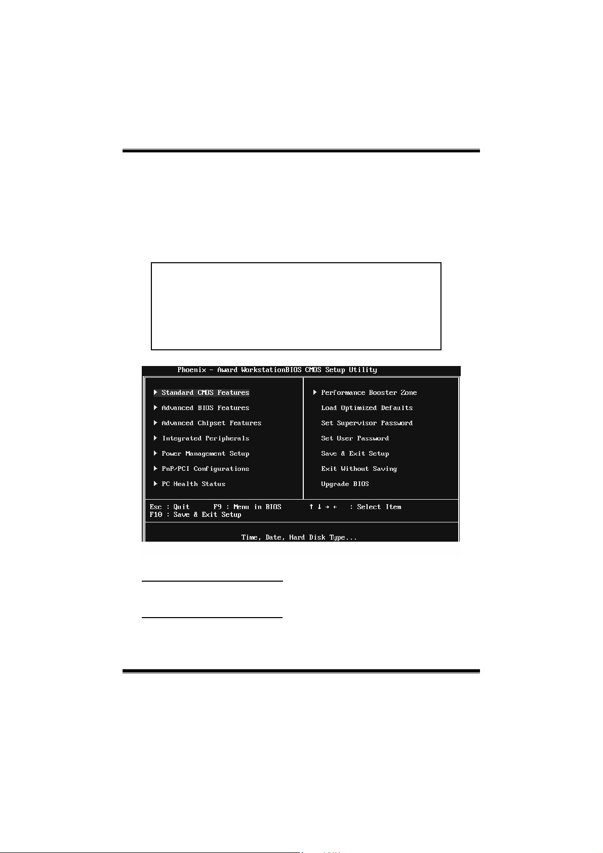
1 Main Menu
Onc e you enter P hoenix-Award BIOS™ CMOS Setup Utility, the Main Menu
will appear o n the screen. The Main Menu allows you to select from several
setup functions. Use the arrow keys to select among the items and press <Enter>
to accept and enter the sub-menu.
!! WARNING !!
For better system performance, the BIOS firmware is being
continuously upd ated. The BIOS infor mat io n des cribed in
this manual (Figure 1, 2, 3, 4, 5, 6, 7, 8, 9) is for yo ur
reference only. The actual BIOS information and settings on
board may be slightly different from this manual.
Figure 1: Main Me nu
Standard CMOS Featu res
This submenu contains industry stand ard configurable options.
Advanced BIOS Features
This submenu allo ws yo u to conf igure ad vanc ed features of the BIOS.
4
Page 5
NF520B A2G+ BIOS Setup
Advanced Chipset Features
This submenu allows you to configure special chips et features.
Integrated Peripherals
This s ubmenu allo ws you to configure cert ain IDE hard drive options and
Programmed Input/ Output features.
Power Management Setup
This submenu allows you to configure the power management features.
PnP/PCI Configurations
This submenu allows you to configure certain “Plug and Play” and PCI options.
PC Health Status
This submenu allows yo u to mo n itor the hardware of your syst em.
Performance Booster Zone
This submenu allows you to change CPU Vcore Voltage and CPU/PCI clock.
(However, we suggest you to use the default setting. Changing the voltage and
cloc k improp erly may d amag e the CP U or M/B!)
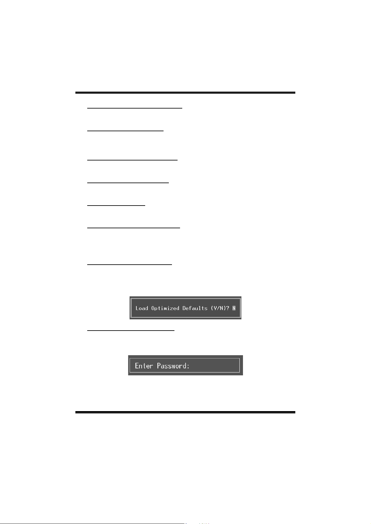
Load Optimized Defaults
This selection allows you to relo ad the BIOS when problem occurs during
system booting sequence. These configurations are factory settings optimized
for this system. A confirmation message will be displayed before defaults are
set.
Set Supervisor Password
Setting the supervisor passwo rd will pro hibit everyone except the supervisor
from making changes us ing the C MOS Setup Utility. You will b e prompted with
to ent er a password.
5
Page 6
NF520B A2G+ BIOS Setup
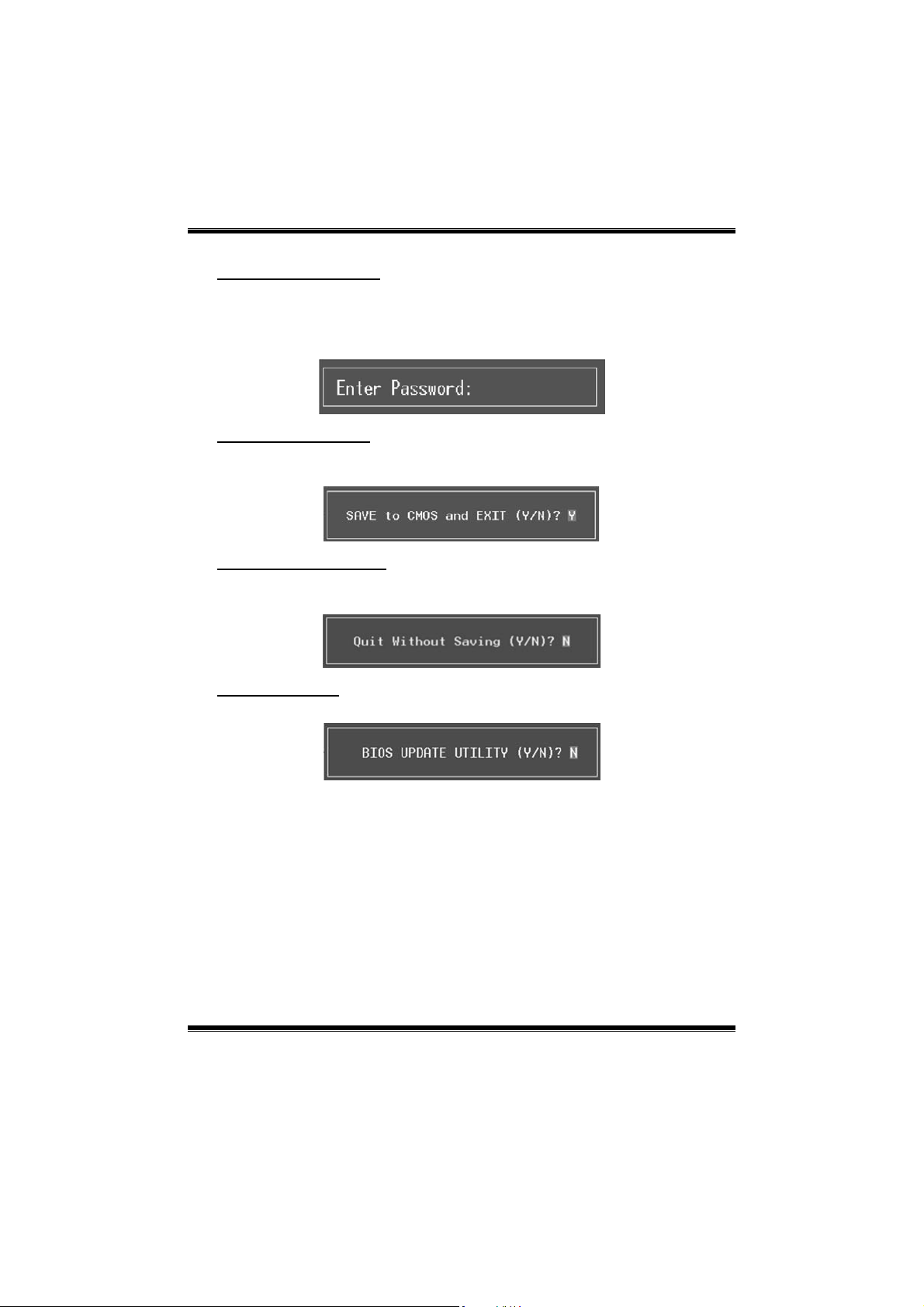
Set User Password
If the Supervisor Pass word is not set, then the User Pass word will func tion in
the same way as the Supervisor Password. If the Supervisor Password is set and
the User Password is set, the “Us er” will only be able to view configurations but
will not be ab le to change them.
Save & Exit Setup
Save all configuration changes to CMOS (memory) and exit setup. Confirmation
message will be displayed before proceeding.
Exit Without Saving
Abandon all changes made during the current session and exit setup.
Confirmation message will be displayed before proceed ing.
Upgrade BIOS
This sub menu allows you to upgrade bios.
6
Page 7
NF520B A2G+ BIOS Setup
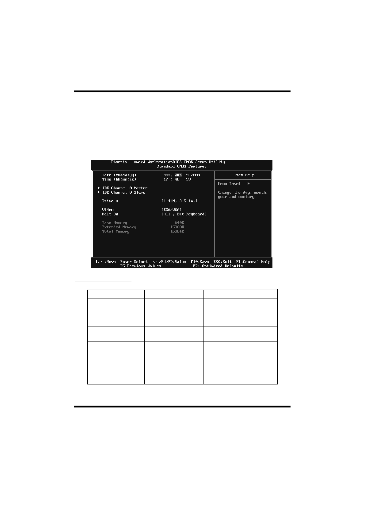
2 Standard CMOS Features
The items in Standard CMOS Setup Menu are divided into several categories.
Each cat egory inc lud es no, one or mor e than one s etup it ems . Us e the arro w
keys to highlight the item and t hen use the<PgUp> or <PgDn> keys to select the
value you want in each item.
Figure 2: Standard CMOS Setup
Main Menu Selec tions
This table sho ws the items and the availab le options on the Main Menu.
Item Options Description
Date mm : dd : yy
Time hh : mm : ss
IDE Channel 0 Master
IDE Channel 0 Slave
Options are in its sub
Options are in its sub
menu.
menu.
Set the system date. Note
that the ‘Day’ automatically
changes when you set the
date.
Set the system internal
clock.
Press <Enter> to enter the
sub menu of detailed
options
Press <Enter> to enter the
sub menu of detailed
options.
7
Page 8

NF520B A2G+ BIOS Setup
Item Options Description
360K, 5.25 in
1.2M, 5.25 in
Drive A
Video
Halt On
Base Memory N/A
Extended Memory N/A
Total Memory N/A
720K, 3.5 in
1.44M, 3.5 in
2.88M, 3.5 in
None
EGA/ VG A
CGA 40
CGA 80
MONO
All Errors
No Errors
All, But Keyboard
All, But Diskette
All, But Disk/ Key
Select the type of floppy
disk drive installed in your
system.
Select the default video
device.
Select the situation in which
you want the BIOS to stop
the POST process and
notify you.
Displays the amount of
conventional memory
detected during boot up.
Displays the amount of
extended memory detected
during boot up.
Displays the total memory
available in the system.
8
Page 9
NF520B A2G+ BIOS Setup
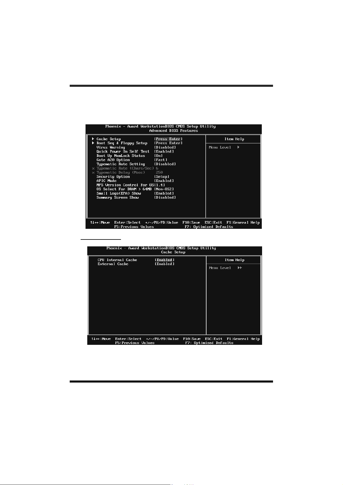
3 Advanced BIOS Features
Figure 3: Advanced BIOS Setup
Cache Setup
9
Page 10
NF520B A2G+ BIOS Setup
CPU Internal Cache
Depending on the CPU/chipset in use, you may be able to increase memory
ac cess time with th is opt io n.
Enabled (default) Enable cache.
Disabled Disable cache.
External Cache
This option enables or disables “Level 2” secondary cache on the CPU, which
may improve performance.
Enabled (default) Enable cache.
Disabled Disable cache.
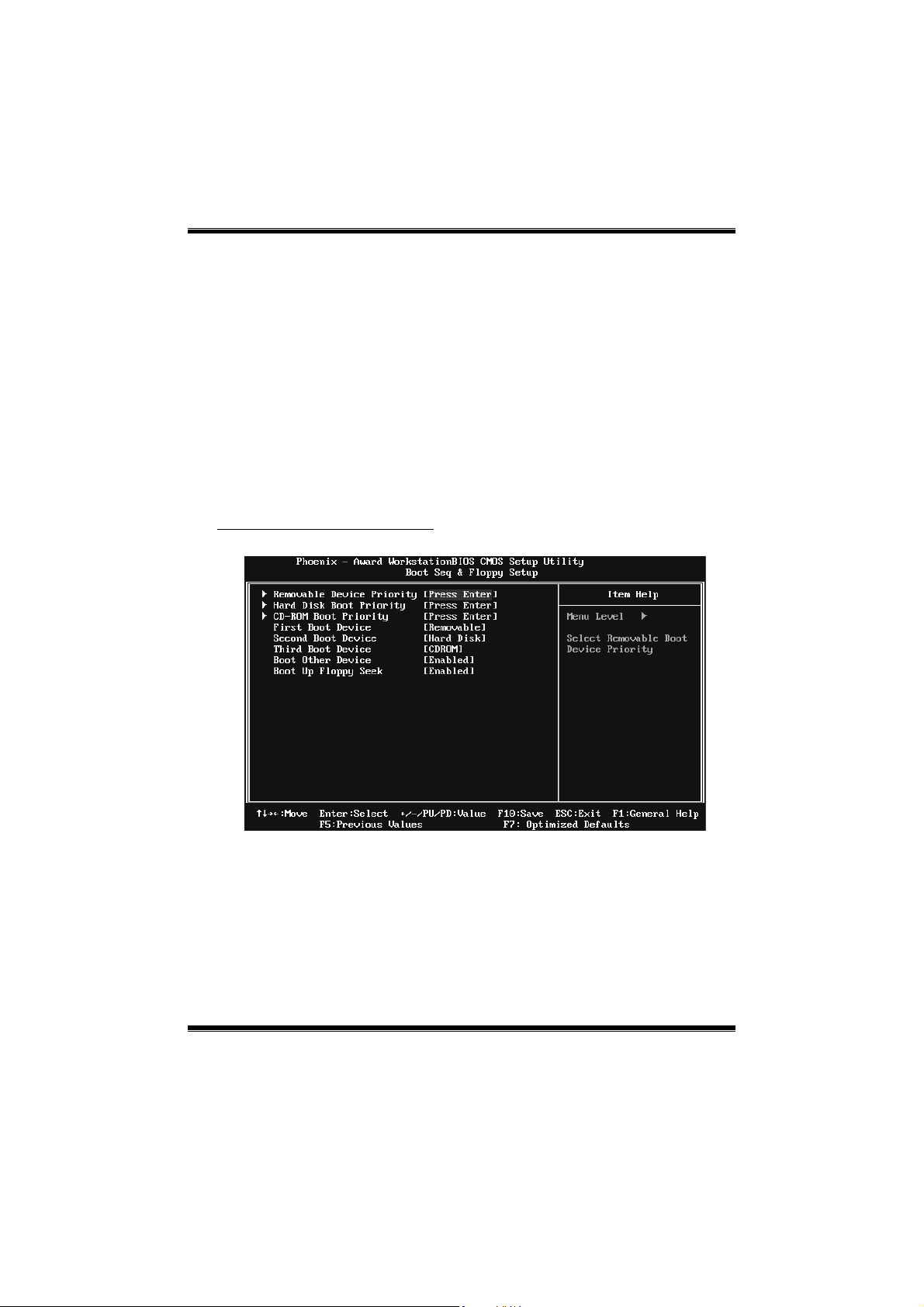
Boot Seq & Floppy Setup
This item allows you to setup boot sequence & Floppy.
10
Page 11
NF520B A2G+ BIOS Setup
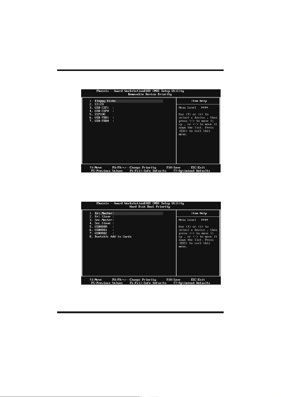
Removable Device Prior ity
Select Removable Boot Device Priority.
The Choices: Flop p y Disks, Zip 100, USB-FDD0, US B-F DD1 , USB-ZIP0,
USB-ZIP1, LS120.
Hard Disk Boot Priority
The BIOS will attempt to arrange the Hard Disk boot s equence
automatically.You can c hange the Hard Disk booting s equence here.
The Choices: Pri. Master, Pri. Slave, Sec. Master, Sec. Slave, USBHDD0,
USBHDD1, USBHDD2, and Bootable Add-in Cards.
11
Page 12
NF520B A2G+ BIOS Setup
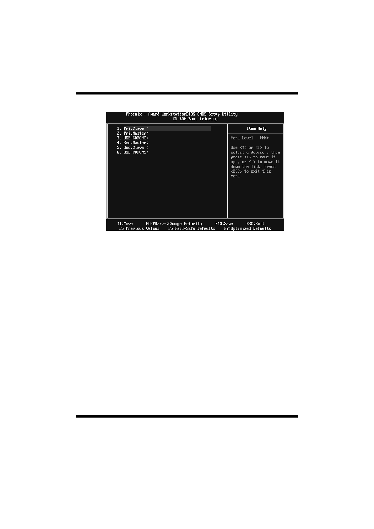
CD-ROM Boot Priority
TheChoices: P ri. Master, Pri. Slave, S ec. Maste r, S ec. Slave, USB-CDROM0,
USB-CDROM1.
First/Second/Third Boot Dev ice
The BIOS will attempt to load the operating system in this order.
The Choices: Removable, Hard Disk, CDROM, Legacy LAN, Disabled.
Boot Other Device
When enabled, BIOS will try to load the operating system from other device
when it failed to load from the three devices above.
The Choices: Enabled (default), Disab led
Boot Up Floppy Seek
When enabled, System will test the floppy drives to determine if they have 40
or 80 tracks during boot up. Disabling this option reduces the time it takes to
boot-up.
The Choices: Enabled (default), Disabled.
12
Page 13

NF520B A2G+ BIOS Setup
Virus Warning
This option allows you to choose the VIRUS Warning feature that is used to
protect the IDE Hard Disk boot sector. If this function is enabled and an attempt
is made to wr ite to the boot sector, BIOS will disp lay a warning message on the
screen and sound an alarm beep.
Disabled (default) Virus protection is disabled.
Enabled Virus protection is activated.
Quick Power On Self Test
Enabling this option will cause an abridged version of the Power On Self-Test
(POS T) to execute after you power up the comput er.
Disabled Normal POST.
Ena bled (default) Enable quick POST.
Boot Up NumLock Status
Selec ts the NumLoc k State after t he s ystem s witched on.
The Choices:
On (default) Numpad is numb er keys.
Off Numpad is arrow keys.
Gate A20 Option
Select if chipset or keyboard controller should control Gate A20.
The Choices:
Normal A pin in the keyboard co ntro ller controls GateA20.
Fast (default) Lets chips et control Gate A20.
Typematic Rate Setting
When a key is held down, the keystroke will repeat at a rate determined by the
keyboard controller. W hen enabled, the typematic rate and typematic delay can
be configured.
The Choices: Disabled (default), Enabled.
Typematic Rate (Chars/Sec)
Sets the rate at whic h a keyst roke is repeated when you hold the key down.
The Choices: 6 (default), 8, 10, 12, 15, 20, 24, 30.
Typematic Delay (Msec)
Sets the delay time after the key is held down before it begins to repeat the
keystroke.
The Choices: 250 (default), 500, 750, 1000.
13
Page 14

NF520B A2G+ BIOS Setup
Security Option
This option wi ll enable only individuals with p ass words to b ring the system
online and/or to use the CMOS Setup Utility.
System: A passwo rd is required for the system to boot and is also
req uir ed to access the Setup Utility.
Setup (default): A pass word is required to acc ess the Setup Utility o nly.
This will o nly app ly if p ass words are set from the S etup main menu.
APIC MODE
Selecting Enabled enables APIC device mode reporting from the BIOS to the
operating system.
The Choices: Enabled (default), Disabled.
MPS Version Control For OS
The BIOS supports version 1.1 and 1.4 of the Intel multiprocessor specification.
Selec t version s upported by the operatio n sys tem running on this co mput er.
The Choices: 1.4 (default), 1.1.
OS Select For DRAM > 64MB
A choice other than Non-OS2 is only used for OS2 systems with memo ry
exceeding 64MB.
The Choices: Non-OS2 (default), OS 2.
Small Logo(EPA) Show
This item allows you to select whether the “Small Logo” shows. Enabled
(default) “Small Logo” shows when system boots up. Disabled No “Small
Logo” shows when system boots
The Choices: Enabled (default), Disabled
Summary Screen Show
This item allo ws you to enable/disable the summary screen. Summary screen
means system configuration and PCI device listing.
The Choices: Disabled (default), Enabled.
14
Page 15

NF520B A2G+ BIOS Setup
4 Advanced Chipset Features
This submenu allows you to configure the specific features of the chipset
installed on your system. This chipset manage bus speeds and access to system
memory resources, such as DRAM. It also coordinates communications with the
PCI bus. The default settings that came with your system have been optimized
and t herefore should no t be changed unless you ar e susp ic ious that the s ett ings
have been changed incorrectly.
Figure 4: Advanced Chipset Setup
PCIE / SATA Spread Spectrum
This item allows you to enable/disable t he Spread Spectrum function.
The Choices: Disabled (default), Triangular Down.
HT Spread Spectrum
This item allows you to select HT Spread Spectrum function.
The choices: Disabled (default), 0. 50% H.Kiss Cntr
SSE/SSE2 instruction
This item allows you to enab le/disable SSE/SSE2 ins truction.
The Choices: Enabled (default), Disabled.
15
Page 16

NF520B A2G+ BIOS Setup
CPU Feature
Virtualization
Virtualization Technology can virtually separate your system resource into
several parts, thus enhance the performance when running virtual machines or
mult i inte rface sy ste ms.
The Choices: Enabled (default), Disabled.
AMD K8 Coo l&Quiet control
The item allows you select K8 Cool’n’Quiet control.
The Choices: Auto (default), Disabled.
CPU-NB FID
The Choices: 800MHz (default), 1000MHz, 1200MHz, 1400MHz, 1600MHz,
Disabled.
CPU DID
The Choices: CPU FREQ/1 (de fault), CP U FR EQ/ 2, CP U FREQ/4, CPU
FREQ/8, CPU FREQ/16.
CP U F ID
The Choices: X8 : 1600MHz (default), X8.5: 1700MHz, X9: 1800MHz.
AMD CPU Stepping
The Choices: P0 (default), P1.
16
Page 17

NF520B A2G+ BIOS Setup
System BIOS Cacheable
Selec ting the “Enabled ” optio n allows caching o f the syste m BIOS R OM at
F0000h-FFFFFh, whic h is able to improve the system performance. However,
any programs that attempts to write to this memory block will cause conflicts
and result in system errors.
The Choices: Disabled (default), Enabled.
17
Page 18

NF520B A2G+ BIOS Setup
5 Integrated Peripherals
Figure 5. Integrated Peripherals
IDE Function Setup
18
Page 19

NF520B A2G+ BIOS Setup
RAID Config
RAID Enable
This option allows you to enable or disable RAID function.
The Choices: Disabled (defa ult ), En able d.
SATA 1 Primary/Secondary RAID
This option allows you to enable or disable SATA Primary/Secondary RAID.
The Choices: Disabled (defa ult ), En able d.
On-ch ip IDE Cha nnel 0
The motherboard chipset contains a PCI IDE interface with support for two
IDE channels. Select “Enabled” to activate the first and/or second IDE interface.
Select “Disabled” to deactivate an interface if you are going to install a primary
and/or secondary add-in IDE interface.
The Choices: Enabled (default), Disabled.
Primary Master/Slave PIO
The IDE PIO (Programmed Input / Output) fields let you set a PIO mode (0-4)
for each of the IDE devices that the onboard IDE interface supports. Modes 0
to 4 will increase performance progressively. In Auto mode, the system
automatically determines the best mode for each device.
The Choices: Auto (default), Mode0, Mode1, Mode2, Mode3, Mode4.
19
Page 20

NF520B A2G+ BIOS Setup
Primary Master/Slave UDMA
Ultra DMA function can be implemented if it is supported by the IDE hard
drives in your system. As well, your operating environment requires a DMA
driver (Windows 95 or OSR2may need a third party IDE bus master driver). If
your hard drive and your system software both support Ultra DMA, select Auto
to enable BIOS support.
The Choices: Auto (default), Disabled.
IDE DMA Transfer Access
This item allows you to enable or disable the IDE DMA transfer access.
The Choices: Enabled (default), Disabled.
Serial-ATA Controller
Enables support for Serial-ATA controller.
The Choices: All Enabled (default), Disabled
IDE Prefetch Mode
The “onboard” IDE drive interfaces supports IDE prefetch function for faster
drive access. If the interface on your drive does not support prefetching, or if
you install a primary and/or secondary add-in IDE interface, set this option to
“Disabled”.
The Choices: Enabled (default), Disabled.
20
Page 21

NF520B A2G+ BIOS Setup
Onboard Device
USB Keyboard/ Storage Support
This item allows you to support the USB legacy devices.
The Choices: Enabled, Disabled (default).
USB Mouse Support
This item allows you to enable or disable the USB Mouse Legacy Support.
Enabled Enable USB Mouse Support.
Disabled (default) Disable USB Mouse Support.
HD Audio
This item allows you to enable or disable to support HD Audio.
The Choices: Auto (default), Disabled.
21
Page 22

NF520B A2G+ BIOS Setup
Onboard I/O Address
Onboard FDC Controller
Select enabled if your system has a floppy disk controller (FDC) installed on
the system board and you wish to use it. If you installed another FDC or the
system uses no floppy drive, select disabled in this field.
The Choices: Enabled (default), Disabled.
Onboard Serial Port 1
Select an address and corresponding interrupt for the first and second serial
ports.
The Choices: 3F8/IRQ4 (default), Disabled, 2F8/IRQ3, 3E8/IRQ4, 2E8/IRQ3,
Auto.
Onboard Parallel Port
This item allows you to determine access onboard parallel port controller with
which I/O Address.
The Choices: 378/IRQ7 (default), 278/IRQ5, 3BC/IRQ7, Disabled.
22
Page 23

NF520B A2G+ BIOS Setup
Parallel Port Mode
This item allows you to determine how the parallel port should function. The
default value is SPP.
The Choices:
SPP (def ault) U sin g Par allel port as Stan dard Prin ter P o rt.
EPP Usin g Paralle l P ort as En hanc ed P a ra llel Port .
ECP Usin g Paralle l po rt as Extended Capa bilit ies P ort.
ECP+EPP Usin g Paralle l port as ECP & EPP mod e.
ECP Mode Use DMA
Select a DMA Channel for the port.
The Choices: 3 (default), 1.
Onboard PCIE LAN
This optio n allo ws you to control PCIE LAN.
The Choices: Enabled (default), Disabled.
Onboard LAN Boot ROM
This item allows you to enab le or dis able the Onboard LAN Boot R O M.
The Choices: Disabled (default), Enabled.
OnChip USB
This option s hould be enabled if your s ystem has a USB ins talled on the system
board. You may need to dis able this feature if you add a higher performance
controller.
The Choices: V1.1+V2.0 (default), Disabled, V1.1
IDE HDD Block Mode
Block mode is also c alled block transfer, multiple commands, or mult iple
sectors read / write. If your IDE hard drive supports block mode (most new
drives do), select Enabled for automatic detection of the optimal number of
block mod e (most new drives do), select Enabled for automatic detect io n of the
optimal number of block read / write per sector where the drive can support.
The Choices: Enabled (default), Disabled.
23
Page 24

NF520B A2G+ BIOS Setup
6 Pow er Management Setup
The Power Management Setup Menu allows you to configure your system to
utilize energy conservation and power up/power down features.
Figure 6. Power Manageme nt Setup
ACPI Function
This item displays the status of the Adv anc ed Configur ation and Power
Management (ACPI).
The Choices: Enabled (default), Disabled.
ACPI Suspend Type
The item allows you to select the susp end typ e unde r the ACPI operat ing
system.
The Choices: S1 (P OS) (d efault) Power on Susp end
S3 (STR) S uspend to RAM
S1 & S3 POS+STR
24
Page 25

NF520B A2G+ BIOS Setup
Power Management
This c ategory allows you to select the po wer saving method and is directly
related to the fo llo wing mod es :
1. HDD Po wer Do wn.
2. Suspend Mode.
There are three options of Power Management, three of which have fixed mode
settings
Min. Power Sa ving
Minimum power management.
Suspend Mode = 1 hr.
HDD Power Down = 15 min
Max. Power Saving
Maximum power management only available for s l CPU’s.
Suspend Mode = 1 min.
HDD Power Down = 1 min.
Use r Define (default)
Allow yo u to set each option individ ually.
When you choose user define, you can adjust each o f the item from 1 min. to 1
hr. except for HDD Po wer Down which ranges from 1 min. to 15 min.
Video Off Method
This option determines the manner when the monitor goes blank.
V/H SYNC+Blank
This selection will cause the system to turn off the vertical and horizontal
synchronization ports and write blanks to the video buffer.
Blank Screen
This optio n only writes blanks to the video buffer.
DPM S S upport
Initial display power management signaling.
HDD Power Down
When enabled, the hard-disk drives will power down after a set time of system
inactivity. All other devices remain active.
The Choices: Disabled (def ault), 1 Min, 2 Min, 3 Min, 4 Min, 5 Min, 6 Min, 7
Min, 8 Min, 9 Min, 10 Min, 11 Min, 12 Min, 13 Min, 14 Min, 15 Min.
(default)
25
Page 26

NF520B A2G+ BIOS Setup
Soft-Off by PBTN
This item determines the behavior o f system power button. Instant off turn off
the po wer immediately, and Delay 4 Sec. will require you to press and hold the
power button for 4 seconds to cut off the system power.
The Choices: Delay 4 Sec, Instant-Off (default).
WOL(PME#)/ From Soft-Off
This item allo ws you to enab le o r dis able Wake On LAN from Soft-Off
function.
The Choices: Disabled (default), Enabled.
WOR(RI#) From Soft-Off
This item allows you to enab le or d isable Wake O n Ring from Soft-Off function.
The Choices: Disabled (default), Enabled.
USB Resume from S3/S4
This item allows you to enab le or dis abled the USB devic e wa ke up fro m S3/S4
function.
The Choices: Disabled (default), Enabled.
S5 Resume by USB
The Choices: Disabled (default), Enabled.
Power-On by Alarm
This function is for setting date and time for your computer to boot up. When
enabled, you c an choose th e date and time to boo t up th e syste m.
The Choices: Disabled (default), Enabled.
Date (of Month) Alarm
You c an c hoos e which month the s ystem will boot up.
Time (hh:mm:ss) Alarm
You can c hoose the system boot up time, inp ut hour, minute and second to
specify.
26
Page 27

NF520B A2G+ BIOS Setup
HPET Support
This item allows you to control the high precision event timer.
The Choices: Enabled (default), Disabled.
POWER ON Function
This item allows you to choose the power on method.
The Choices: Button Only (default), Password, Hot Key, Mouse Mo ve/Click,
Mouse Double Click, Any Key, Keyboard 98.
KB Power ON Password
Input password and press Enter to set the Keyboard power on password.
Hot Key Power ON
Choos e the Hot Key comb ination to boot up the system.
The Choices: Ctrl-F1 (default), Ctrl-F2, Ctrl-F3, Ctrl-F4, Ctrl-F5, Ctrl-F6,
Ctrl-F7, Ctrl-F8, Ctrl-F9, Ctrl-F10, Ctrl-F11, and Ctrl-F12.
PWRON After PWR-Fail
This s etting spec ifies how your system should behave after a po wer fail or
interrupts occurs. By c hoos ing off will leave the co mputer in the po wer off state.
Choosing On will reboot the computer. Former-Sts will restore the system to the
status befo re power failure or interrupt occ urs.
The Choices: Off (default), On, Former-Sts.
27
Page 28

NF520B A2G+ BIOS Setup
7 PnP/PCI Configurations
This section describes configuring the PCI bus s ystem. PCI, or Personal
Computer Interconnect, is a system which allows I/O devices to op erate at
speeds nearing the speed of the CPU itself uses when communicating with its
own special co mponents. This section covers some very technical items and it is
strongly reco mmended that only experienced users should make any changes to
the default settings.
Figure 7: PnP/PCI Configurations
Init Display First
With systems that have multip le video cards, this item determines whether the
primary display uses a PCI Slot or an AGP Slot.
The Choices: PCIEx (d efault), P CI Slot, Onboard.
28
Page 29

NF520B A2G+ BIOS Setup
Reset Configuration Data
The s ystem BIOS s upports the P nP feature which req uires the s ystem to reco rd
whic h reso urc es ar e assigned and pro t ects resourc es fro m conflict.
Every pe ripheral device has a node, which is called ESC D. This node records
whic h resources are assigned to it. T h e system needs to record and updat e ESCD
to the memory loc ations. T hese locations are reser ved in the sys tem BIOS. If the
Disabled (default) option is chosen, the system‘s ESCD will update only when
the new co nf igurat ion varies fro m the las t one. If t he Enabled optio n is chos en,
the system is forced to update ESCDs and then is automatically set to the
“Disabled” mode.
The above set tings will be shown on the screen o nly if “Manual” is chose n for
the resources co ntro lled by funct ion.
Legac y is the term, which signifies that a resource is ass igned to the ISA Bus
and p rovides non-P nP ISA add -on cards. PC I / IS A P nP signify that a reso urce
is assigned to the PCI Bus or provides for ISA PnP add-on cards and
peripherals.
The Choices: Disabled (default), Enabled.
Resources Controlled By
By Choos ing “Auto(ESCD)” (default), the system BIOS will detect the system
resources and automatically assign the relative IRQ and DMA channel for each
peripheral. By Choosing “Manual”, the user will need to ass ign IRQ & DMA for
add-on cards. Be sure that there are no IRQ/DMA and I/O port conflicts.
The Choices: Auto (ESCD) (default), Manual.
IRQ Resources
This submenu will allow you to assign each system interrupt a type, depending
on the type of device using the interrupt. When you press the “Press Enter” tag,
you will be directed to a submenu that will allow you to configure the system
interrupts. T his is only configurable when “Resources Contro lled By” is set to
“Manual”.
IRQ-5 ass igned to PCI Device
IRQ-7 ass igned to PCI Device
IRQ-9 ass igned to PCI Device
IRQ-10 ass igned to PCI Device
IRQ-11 ass igned to PCI Device
IRQ-14 ass igned to PCI Device
IRQ-15 ass igned to PCI Device
29
Page 30

NF520B A2G+ BIOS Setup
PCI / VGA Palett e Snoop
Some old grap hic controllers need to “snoop” on the VGA palette and then map
it to their display as a way to provide boot information and VGA compatibility.
This item allows such snooping to take place.
The Choices: Disabled (default), Enabled.
Ma xi mu m Pa ylo ad Size
Set t he maximum payload s ize fo r Tra nsac tio n packets (TLP).
The Choice: 4096 (default.), 128, 256, 512, 1024, 2048.
30
Page 31

NF520B A2G+ BIOS Setup
8 PC Health Status
Figure 8: PC Health Status
Smart Fan Option
31
Page 32

NF520B A2G+ BIOS Setup
CPU Smart Fan
Smart Fan Calibration
PWM Duty Off< >℃
PWM Duty Start< >℃
Start PWM Value
Smart F an Slope
T his item al lows yo u to c ontrol the C PU Fan.
The Choices: Disabled (default), Auto, 4-pin, 3-pin..
Choose this item and then the BIOS w ill auto test and detect the CPU fan
functions and show CPU fan speed.
If the CPU Temperature is lower than the set value, FAN will turn off.
The Choices: Min=0,.Max=127, Key in a DEC number.
CPU fan starts to work under smart fan function when arrive this set
value.
The Choices: Min=0,.Max=127, Key in a DEC number.
Whe n CPU temperatu re arrives to th e set valu e, t he CPU fan will wo rk
under Smart Fan F unc tion mod e. The range is from 0~127, with an
interval of 1.
The Choices: Min=0,.Max=127, Key in a DEC number.
Incr easing the value of s lop e PW M will rais e the sp eed of CPU fan.
The Choices: Min=1,.Max=127, Key in a DEC number.
Shutdown Temperature
This item allows you to set up the CP U shutdown Temperature. This item is
only effective under W indows 98 ACPI mode.
The Choices: Disabled (default), 60 / 140 , 65 / 149℃℉℃℉, 70 / 15 8℃℉,
75 / 1℃ 67℉, 80 / 1℃ 76 ,℉ 85 / 1℃ 85℉, 90 / 1℃ 67 .℉
Show H/W Monitor in POST
If you computer c o ntains a mo nito ring syste m, it wi ll s how P C health s tatus
during POST stage. The item offers several different delay times.
The Choices: Enabled (default), Disabled.
CPU Vcore, Chipset Voltage, +3.3V, +5.0V, +12.0V, DDR/HT
Voltage, 5V (SB)
Detect t he system’s voltage status automat ically.
32
Page 33

NF520B A2G+ BIOS Setup
CPU Temp
This field displays t he c urrent temperature of CPU.
Current CPU FAN Speed
This field displays t he c urrent sp eed o f CPU fa n.
Current SYS FAN Speed
This field displays t he c urr ent sp eed SYSTEM fan.
33
Page 34

NF520B A2G+ BIOS Setup
9 Performance Booster Zone
Fig ure 9: Perfo rmance Boos ter Zone
CPU VID Control
This function allows yo u to adjus t the CPU vo ltage.
The Choices: Default (default), +7.5%, +15%, +23%.
CHIP VID Control
This funct ion allows you to adjust the chipset voltage.
The Choices: 1.25V (default), 1.35V, 1.45V, 1.55 V
HT Voltage Control
This funct ion allows you to adjust the HT voltage.
The Choices: Default (default), +4%, +8%, +12V%.
Memory Voltage
This item allows you to select memory Voltage.
The Choices: 1.95 V (default), 2.05V, 2.15V, 2.25V, 2.35V, 2.54V, 2.55 V,
2.65V
34
Page 35

NF520B A2G+ BIOS Setup
CPU Frequency
This item allows you to select the CPU Frequenc y.
The Choices: 200.0 (default), 201.0~450.0.
PCIE Clock
The Choices: 100MHz (d efault), 101MHz ~ 150MHz
K8<->NB HT Speed
This item allows you to select the K8<-> NB HT Speed.
The Choices: Auto (default), 1x, 2x, 3x, 4x, 5x.
K8<->NB HT Width
This item allows you to select the K8<-> NB HT width.
The Choices: Auto (default), ↓8↑8, ↓16↑16.
DRAM Configuration
Timing Mode
The Choices: Auto ( default) , MaxMem Clk, Man ual.
Memory Clock value or Limit
The Choices: DDR 400 (default), DDR 533, DDR 667, DDR 800, DDR1066
(with AM2 + CP U)
35
Page 36

NF520B A2G+ BIOS Setup
DCTs Mode
This item controls the DRAM controller ganged (128bit*1) / unganged
(64bit*2) dual-channel operation mode. If two DRAM modules with different
size are installed, using un gan ged mode can still make it run in dual-channel
operation.
The Choices: Unganged (default), Ganged.
CKE base po wer dow n mode
The Choices: Disabled (default), Enabled.
CKE base powerdown
The Choices: Per Channel (default), P er CS.
Memclock tri-stating
The Choices: Disabled (default), Enabled.
Memory Hole Remapping
The Choices: Enabled (default), Disabled.
Auto Optimize Bottom IO
The Choices: Enabled (default), Disabled.
Bottom of [31:24] IO space
The Choices: Min=0000 Max=00FF; Key in a HEX number.
Bottom of UM A D RAM [3 1:24]
The Choices: Min=0000 Max=00FC; Key in a HEX number.
DDRII Timing Item
The Choices: Disabled (default), Enabled.
TwTr Command Delay
The Choices: 3 bus clocks (default), 1 bus clocks, 2 bus clocks.
Trfc0 for DIMM0
The Choices: 75ns (default), 105ns, 127.5ns, 195ns, 327.5ns.
Trfc1 for DIMM1
The Choices: 75ns (default) , 105ns, 127.5ns, 195ns, 327.5ns.
36
Page 37

NF520B A2G+ BIOS Setup
<Twr> Write Recovery Time
The Choices: 6 bus clocks (default), 3 bus clocks, 4 bus clocks, 5 bus clocks.
<Trtp> Precharge Time
The Choices: 3 clocks (default), 2 clocks.
<Trc> Row Cycle Time
The Choices: 26 bus clocks (default), 11-25 bus clocks.
<Trcd> RAS to CAS R/W Delay
The Choices: 6 clocks (default), 3 clocks, 4 clocks, 5 clocks.
<Trrd> RAS to RAS Delay
The Choices: 5 clocks (default), 2 clocks, 3 clocks, 4 clocks.
<Trp> Row Precharge Time
The Choices: 6 clocks (default), 3 clocks, 4 clocks, 5 clocks.
<Tras> Minimum RAS Active T
The Choices: 18 bus clocks (default), 5-17 bus clocks.
Special Notice:
If the system’ s frequency that you have selected is not func tioning, t here are t wo methods
to boot the sys tem.
Method 1:
Clear the CMOS data by s etting the JCMOS1 ((2-3) closed)) as “ON” status. All the
CMOS d ata will be loaded as defaults sett ing.
Method 2:
Press the <Ins ert> key and Power b utton simultaneous ly, after that keep -on press ing the
<Ins ert> key until the power-on screen showed.
This action will boot-up the system according to FSB of the processor
It’s strongly recommended to set CPU Vcore and c lock in default setting. If the CPU
Vcore and clock are not in default s etting, it may cause CPU or M/B damage.
37
 Loading...