

Page 1

NF520B A2G+ Setup Manual
FCC Information and Copyright
This equipment has been tested and found to comply with the limits of a Class
B digital device, pursuant to Part 15 of the FCC Rules. These limits are designed
to provide reasonable protection against harmful interference in a residential
installation. This equipment ge nerates, uses, and can radiate radio frequency
energy and, if not i nstalled and used in accordance with the instructions, may
cause harmful interference to radio communications. There is no guarantee
that interference will not occur in a particular installation.
The vendor makes no representations or warranties with respect to the
contents here and specially disclaims any implied warranties of merchantability
or fitness for any purpose. Further the vendor reserves the right to revise this
publication and to make changes to the contents here without obligation to
notify any party beforehand.
Duplication of this publication, in part or in whole, is not allowed without first
obtaining the vendor’s approval in writing.
The content of this user’s manual is subject to be changed without notice and
we will not be responsible for any mistakes found in this user’s manual. All the
brand and product names are trademarks of their respective companies.
Page 2

Table of Contents
Chapter 1: Introduction ........................................ 1
1.1 Before You Start ................................................................................ 1
1.2 Package Checklist............................................................................. 1
1.3 Motherboard Features...................................................................... 2
1.4 Rear Panel Connectors ..................................................................... 3
1.5 Motherboard Layout......................................................................... 4
Chapter 2: Hardware Installation .......................... 5
2.1 Installing Central Processing Unit (CPU)....................................... 5
2.2 FAN Headers...................................................................................... 7
2.3 Installing System Memory ................................................................ 8
2.4 Connectors and Slots....................................................................... 10
Chapter 3: Headers & Jumpers Setup .................. 13
3.1 How to Setup Jumpers .................................................................... 13
3.2 Detail Settings.................................................................................. 13
Chapter 4: NVIDIA RAID Functions...................... 17
4.1 Operating System............................................................................ 17
4.2 Raid Arrays ...................................................................................... 17
4.3 How RAID Works............................................................................. 17
Chapter 5: Useful Help ........................................ 19
5.1 Driver Installation Note.................................................................. 19
5.2 Software............................................................................................ 20
5.3 Award BIOS Beep Code.................................................................. 21
5.4 Extra Information............................................................................ 21
5.5 Troubleshooting............................................................................... 22
Appendix: SPEC In Other Languages ................... 24
German.................................................................................................................. 24
French .................................................................................................................... 26
Italian..................................................................................................................... 28
Spanish ................................................................................................................... 30
Portugue se ............................................................................................................ 32
Polish...................................................................................................................... 34
Russian ................................................................................................................... 36
Arabic..................................................................................................................... 38
Japanese ................................................................................................................ 40
Page 3
CHAPTER 1: INTRODUCTION
NF520B A2G+
1.1 B
EFORE YOU START
Thank you for choosing our product. Before you start installing the
motherboard, please make sure you follow the instructions below:
Prepare a dry and stable working environment with
sufficient lighting.
Always disconnect the computer from power outlet
before operation.
Before you take the motherboard out from anti-static
bag, ground yourself properly by touching any safely
grounded appliance, or use grounded wrist strap to
remove the static charge.
Avoid touching the components on motherboard or the
rear side of the board unless necessary. Hold the board
on the edge, do not try to bend or flex the board.
Do not leave any unfastened small parts inside the
case after installation. Loose parts will cause short
circuits which may damage the equipment.
Keep the computer from dangerous area, such as heat
source, humid air and water.
1.2 PACKAGE CHECKLIST
HDD Cable X 1
Serial ATA Cable X 1
Rear I/O Panel for ATX Case X 1
User’s Manual X 1
Fully Setup Driver CD X 1
FDD Cable X 1 (optional)
USB 2.0 Cable X1 (optional)
S/PDIF out Cable X 1 (optional)
Note: The package contents may be different due to area or your motherboard version.
1
Page 4
Motherboard Manual
/
1.3 MOTHERBOARD FEATURES
Socket AM2+
CPU
FSB
Chipset
Super I/O
Main
Memory
IDE
SATA
LAN
Sound
Slots
On Board
Connectors
AMD Athlon 64 / Athlon 64 FX
/ Sempron / Phenom / Pheno m II processors
(Maximum Watt: 95W)
Support HyperTransport 2.0
Supports up to 2.0 GT/s Bandwidth
nVIDIA nForce 520LE
ITE 8718
Prov ides the most commonly us ed legacy
Super I/O funct ionality.
DDR2 DIMM Slot x 4
Each DIMM supports 256MB/512MB/
1GB/2GB/4GB DDR2
Max Memory Capicity 16GB
Int egr ated IDE Co n t ro l le r
Integrated Serial ATA Controller
Realtek RTL 8111DL
ALC662
PCI Slot x3 Supports PCI expansion cards
PCI Express x16 Slot x1 Supports PCI-E x16 expansion card
PCI Express x 1 Slot x1 Supports PCI-E x1 expansion cards
Floppy Connector x1 Each connector supports 2 Floppy drives
Printer Port Connector x1 Each connector supports 1 Printer port
IDE Conn ector x1 Each conne ctor s upports 2 IDE device
Athlon 64 x2
SPEC
AMD 64 Architecture enables 32 and 64 bit computing
Supports Hyper Transport and Cool=n=Quiet
Low Pin Count Interface
En v ironm en t Cont rol init iatives ,
H/W Mon itor
Fan Sp eed Controller
ITE's "S mart Guard ian" function
Dual Channel Mode DDR2 me mory mo du le
Supports DDR2 533/667/800
Supports DDR2 1066 (by AM2+ / A M3 CPU)
Register ed DIMM and ECC D IMM is not supported
Ultra DMA 33 / 66 / 100 / 133 Bus Master Mode
supports PIO Mode 0~4,
Data transfer rates up to 3.0 Gb/s.
SATA Version 2.0 s p e c if icat ion co mpliant .
10 / 100 Mb/s / 1Gb/s auto negot iation
Half / Full duplex capability
5.1 channels audio out
Supports HD Audio
2
Page 5
Back Panel
I/O
Board Size
Special
Feature
OS Support
NF520B A2G+
SPEC
SATA Connector x2 Each conne ctor s upports 1 SATA devices
Front Panel Connector x1 Supports front panel facilities
Front Audio Connector x1 Supports front panel audio function
CD-in Connector x1 Supports CD audio-in function
S/PDIF out Connector x1 Supports digital audio out function
CPU Fan Header x1 CPU Fan power supply (with Smart Fan function)
System Fan Header x1 System Fan Power supply
USB Connecto r x2 Each connector supports 2 front panel USB ports
CMOS clear Header x1 Restore CMOS data to factory default
Power Connector (24pin) x1 Connects to Power supp ly
Power Conn ector (4pin) x1 Connects to Power supply
PS/2 Keyboard x1
PS/2 Mous e x1
Serial Port x1
LAN port x1
USB Port x4
Audio Jack x3
200 mm (W) x 293 mm (L)
RAID 0 / 1 support
Windows XP / Vista 32 / 64 / Windows 7
Connects to PS/2 Keybo ard
Connects to PS/2 Mouse
Connects to RS-232 Port
Connect to RJ- 45 ethe rnet cab le
Connect to USB devices
Provide Audio-In/Out and microphone connection
Biostar reserves the right to add or remove support for
any OS with or without notice.
1.4 REAR PANEL CONNECTORS
PS/2
Mouse
P S /2
Keyboard
COM1 US BX2USBX2
LAN
Line In/
Surround
Line Out
Mic In 1/
Bass/ Cente r
3
Page 6
Motherboard Manual
1.5 MOTHERBOARD LAYOUT
KBMS1
COM1
F_ PR INT 1
USB1
RJ45USB1
AUDI O2
LAN
JUSBV1
F_AUDIO 1
ATXP WR2
ATX PWR1
nForce
520LE
CPU_FAN1
Socket AM2+
DIMMA1
DIMMB1
DIMMB2
DIMMA2
IDE 1
4
Cod ec
CD_ IN1
Super I/O
Note: represents the 1■
PEX1_1
SPDIF1
PCI1
PCI2
PCI3
PEX16_1
st
BAT1
pin.
JCMO S1
F_USB1 F_USB2
JUSBV2
FDD1
SYS_FAN1
SATA1 SATA 2
PAN EL 1
BIOS
Page 7
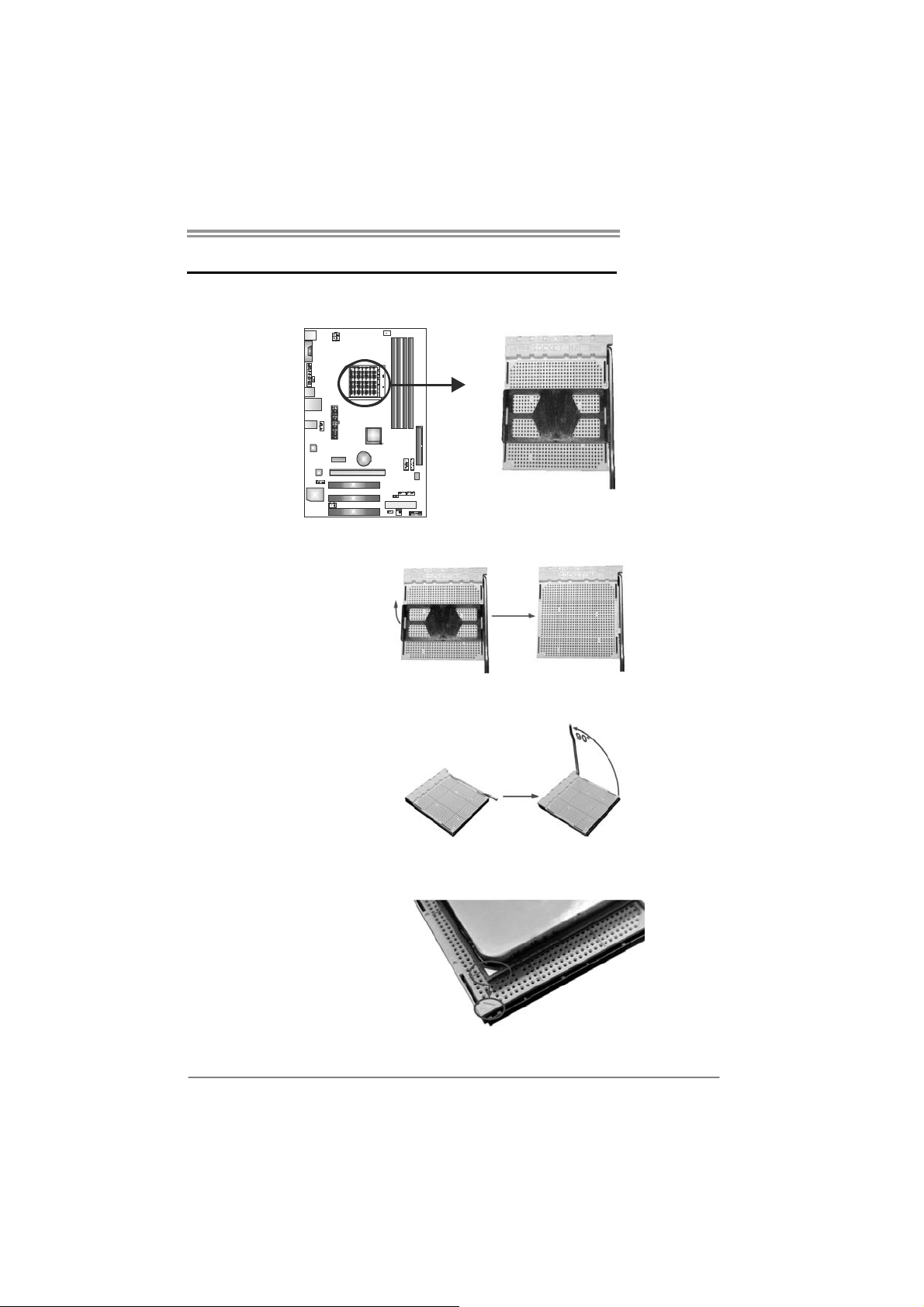
CHAPTER 2: HARDWARE INSTALLATION
NF520B A2G+
2.1 I
NSTALLING CENTRAL PROCESSING UNIT (CPU)
Step 1: Remove the socket protection cap.
Step 2: Pull the lever toward direction A from the socket and then raise the
lever up to a 90-degree angle.
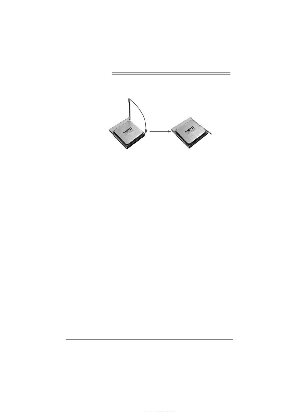
Step 3: Look for the white triangle on socket, and the gold triangle on
CPU should point forwards this white triangle. The CPU will fit
only in the correct orientation.
5
Page 8
Motherboard Manual
Step 4: Hold the CPU down firmly, and then close the lever toward direct
B to complete the installation.
Step 5: Put the CPU Fan on the CPU and buckle it. Connect the CPU
FAN power cable to the CPU_FAN1. This completes the
installation.
Note: Please update the BIOS to the latest version while using AM2+ CPUs. D ue to the latest CPU
transition, you may encounter the situation that the new system failed to boot while using new
AM2+ CPUs. In this case, please install one standard AM2 CPU to boot your system, and
update the latest BIOS from our website for AM2+ CPUs support.
6
Page 9
NF520B A2G+
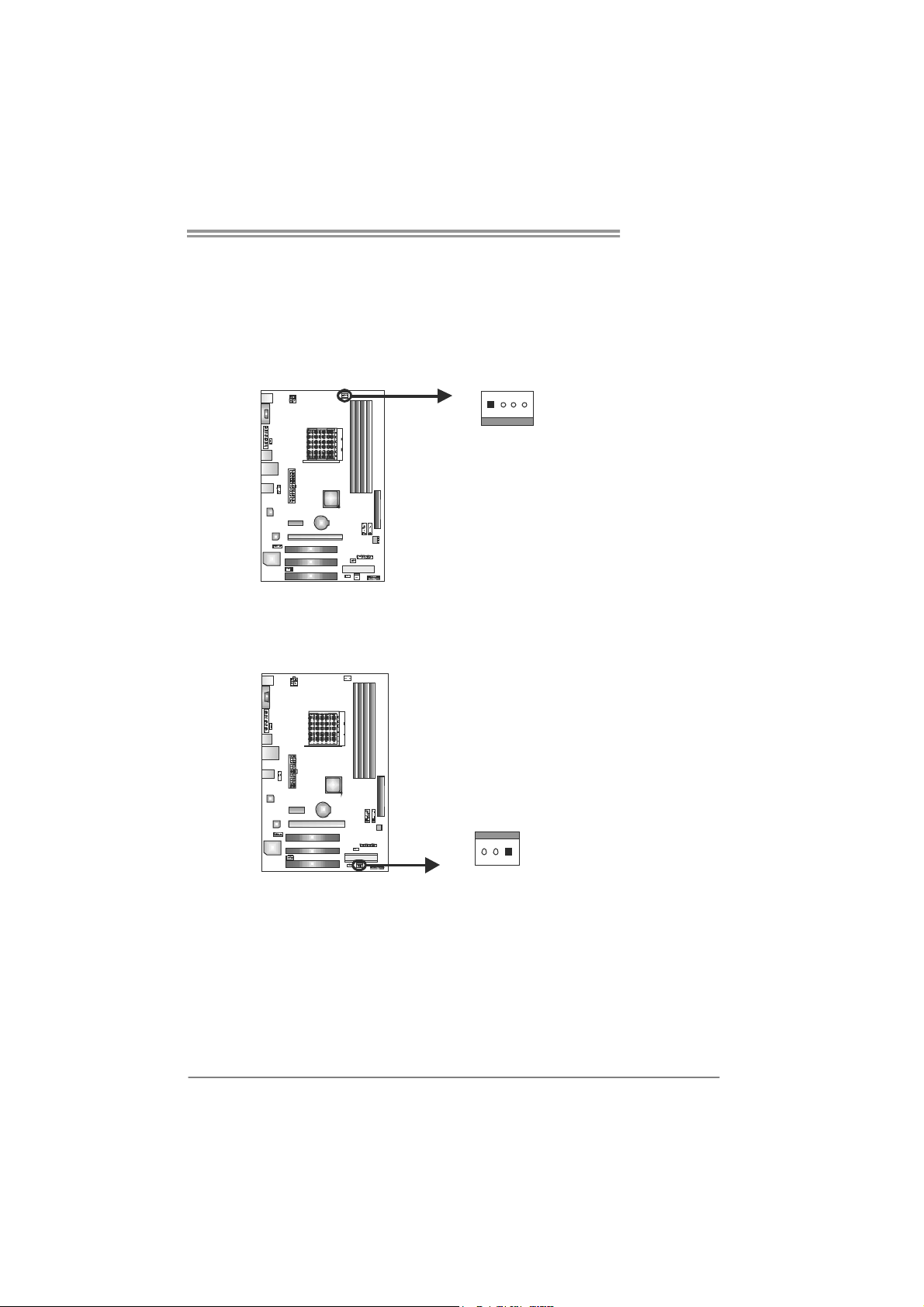
2.2 FAN HEADERS
These fan headers support cooling-fans built in the computer. The fan
cable and connector may be different according to the fan manufacturer.
Connect the fan cable to the connector while matching the black wire to
pin#1.
CPU_FAN1: CPU Fan Header
14
SYS_FAN1: System Fan Header
Pin
Pin
Assignment
1 Ground
2 +12V
3 FAN RPM
rate sense
4
Smart Fan
Control
Assignment
1 Ground
2 +12V
3 FAN RPM rate
sense
13
Note:
The CPU_FAN1 supports 4-pin head connector, and SYS_FAN1supports 3-pin head
connector. When connecting with wires onto connectors, please note that the red wire is
the positive and should be connected to pin#2, and the black wire is Ground and should
be connected to GND.
7
Page 10
Motherboard Manual
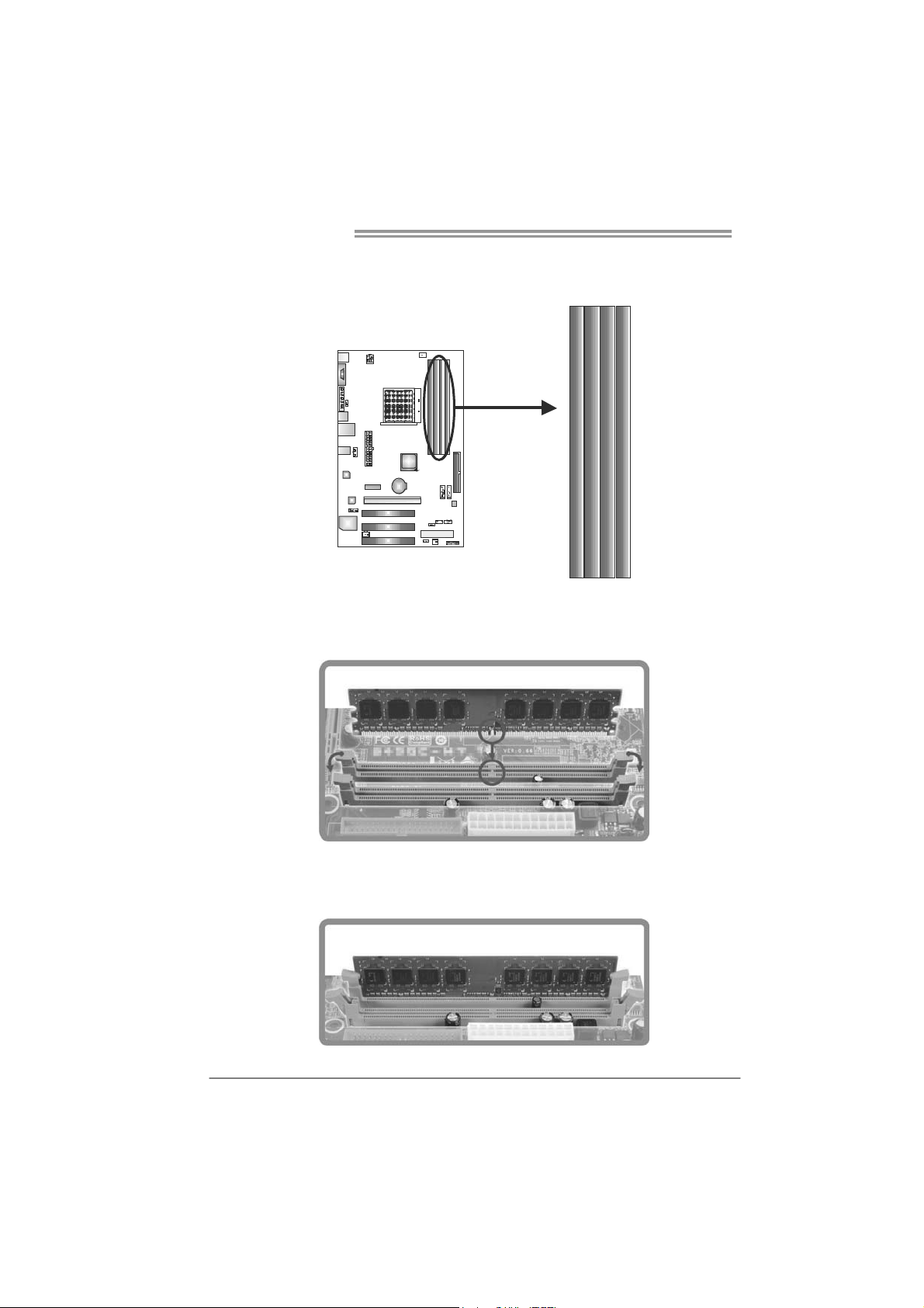
2.3 INSTALLING SYSTEM MEMORY
A. Memory Modules
DIMMA1
DIMMB1
DIMMB2
DIMMA2
1. Unlock a DIMM slot by pressing the retaining clips outward. Align a
DIMM on the slot such that the notch on the DIMM matches the
break on the Slot.
2. Insert the DIMM vertically and firmly into the slot until the retaining
chip snap back in place and the DIMM is properly seated.
8
Page 11
NF520B A2G+
B. Memory Capacity
DIMM Socket
Location
DIMMA1 256MB/512MB/1GB/2GB/4GB
DIMMB1 256MB/512MB/1GB/2GB/4GB
DIMMA2 256MB/512MB/1GB/2GB/4GB
DIMMB2 256MB/512MB/1GB/2GB/4GB
DDR2 Module
Total Mem o ry
Size
Max is 16GB.
C. Dual Channel Memory installation
Please refer to the following requirements to activate Dual Channel function:
Install memory module of the same density in pairs, shown in the table.
Dual Channel Status
Enabled O O X X
Enabled X X O O
Enabled O O O O
(O means memory installed, X means memory not installed.)
The DRAM bus width of the memory module must be the same (x8 or
x16)
DIMMA1
DIMMB1 DIMMA2 DIMMB2
9
Page 12
Motherboard Manual
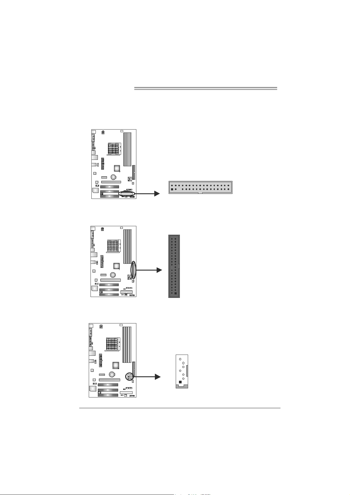
2.4 CONNECTORS AND SLOTS
FDD1: Floppy Disk Connector
The motherboard provides a standard floppy disk connector that supports 360K,
720K, 1.2M, 1.44M and 2.88M floppy disk types.
2
1
34
33
IDE1: Hard Disk Connector
The motherboard has a 32-bit Enhanced PCI IDE Controller that provides PIO
Mode 0~4, Bus Master, and Ultra DMA 33/66/100/133 functionality.
3940
21
SATA1/SATA2: Serial ATA Connectors
The motherboard has a PCI to SATA Controller with 2 channels SATA interface,
it satisfies the SATA 2.0 spec and with transfer rate of 3.0Gb/s.
Pin
Assignment
1 Ground
SATA1 SATA2
7
4
1
2 TX+
3 TX4 Ground
5 RX6 RX+
7 Ground
10
Page 13
NF520B A2G+
PEX16_1: PCI-Express x16 Slot
- PCI-Express 1.0a compliant.
- Maximum theoretical realized bandwidth of 4GB/s simultaneously per
direction, for an aggregate of 8GB/s totally.
PEX1_1: PCI-Express x1 Slot
- PCI-Express 1.0a compliant.
- Data transfer bandwidth up to 250MB/s per direction; 500MB/s in total.
- PCI-Express supports a raw bit-rate of 2.5Gb/s on the data pins.
- 2X bandwidth over the traditional PCI architecture.
PEX1_1
PEX16_1
PCI1/PCI2/PCI3: Peripheral Component Interconnect Slots
This motherboard is equipped with 3 standard PCI slots. PCI stands for
Peripheral Component Interconnect, and it is a bus standard for expansion
cards. This PCI slot is designated as 32 bits.
PCI1
PCI2
PCI3
11
Page 14

Motherboard Manual
ATXP W R1: AT X Power Source Connector
ATXPWR1 allows user to connect 24-pin power connector on the ATX power
supply.
12
1
Pin Assignment Pin Assignment
24
13
1 +3.3V 13 +3.3V
2 +3.3V 14 -12V
3 Gro und 15 Gro und
4 +5V 16 PS_ON
5 Gro und 17 Gro und
6 +5V 18 Ground
7 Gro und 19 Gro und
8 PW_OK 20 NC
9 Standby Voltage+5V 21 +5V
10 +12V 22 +5V
11 +12V 23 +5V
12 +3.3V 24 Ground
ATXP W R2: AT X Power Source Connector
Connecting this connector will provide +12V to CPU power circuit.
1
2
43
Pin
1 +12V
2 +12V
3 Ground
4 Ground
Assignment
12
Page 15

CHAPTER 3: HEADERS & JUMPERS SETUP
NF520B A2G+
3.1 H
OW TO SETUP JUMPERS
The illustration shows how to set up jumpers. When the jumper cap is
placed on pins, the jumper is “close”, if not, that means the jumper is
“open”.
Pin opened Pin closed Pin1-2 closed
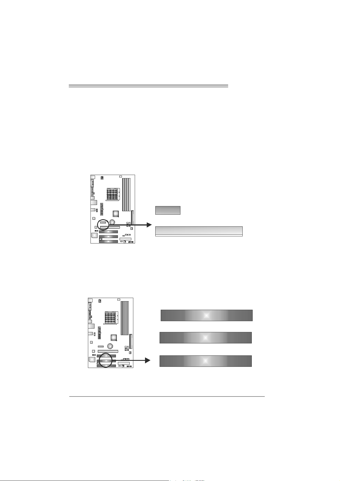
3.2 D
PANEL1: Front Panel Header
This 16-pin connector includes Power-on, Reset, HDD LED, Power LED,
speaker Connection. It allows user to connect the PC case’s front panel
switch functions.
ETAIL SETTINGS
9
1
PWR_LED
++
SPK
On/Off
-
-
+
HLED
16
8
RST
Pin Assignment Function Pin Assignment Function
1 +5V 9 N/A
2 N/A 10 N/A
3 N/ A 1 1 N/ A N/A
4 Speaker
5 HDD LED (+) 13 Power LED (+)
6 HDD LED (-)
7 Ground 15 Power button
8 Reset control
Speaker
Connector
Hard drive
LED
Reset button
12 Power LED (+)
14 Power LED (-)
16 Ground
N/A
Power LED
Power-on button
13
Page 16

Motherboard Manual
F_AUDIO1: Front Panel Audio Header
This header allows user to connect the front audio output cable with the PC front
panel. This header allows only HD audio front panel connector; AC’97 connector
is not acceptable.
CD_IN1: CD-ROM Audio-in Connector
This connector allows user to connect the audio source from the variaty devices,
like CD-ROM, DVD-ROM, PCI sound card, PCI TV turner card etc.
Pin Assignment
12
910
10 Jack Sense
14
1 Mic Left in
2 Ground
3 Mic Right in
4 GPIO
5 Right line in
6 Jack Sense
7 Front Sense
8 Key
9 Left line in
Assignment
Pin
1 Left Channel
Input
2 Ground
3 Ground
4 Right Channel
Input
SPDIF1: Digital Audio-out Connector
This connector allows user to connect the PCI bracket SPDIF output header.
14
Pin
Assignment
1 +5V
2 SPDIF_OUT
3 Ground
13
Page 17

NF520B A2G+
JUSBV1/JUSBV2: Power Source Headers for USB Ports
Pin 1-2 Close:
JUSBV1: +5V for USB ports at USB1/RJ45USB1.
JUSBV2: +5V for USB ports at front panel (F_USB1/F_USB2).
Pin 2-3 Close:
JUSBV1: +5V STB for USB ports at USB1/ RJ45USB1.
JUSBV2: +5V STB for USB ports at front panel (F_USB1/F_USB2).
3
JUSBV1
3
1
13
JUSBV2
1
Pin 1-2 close
3
1
Pin 2-3 close
JCMOS1: Clear CMOS Header
Placing the jumper on pin2-3 allows user to restore the BIOS safe setting and
the CMOS data. Please carefully follow the procedures to avoid damaging the
motherboard.
13
13
13
Pin 1-2 Close:
Normal Operation
(default).
Pin 2-3 Close:
Clear CMOS data.
※ Clear CMOS Procedures:
1. Remove AC power line.
2. Set the jumper to “Pin 2-3 close”.
3. Wait for five seconds.
4. Set the jumper to “Pin 1-2 close”.
5. Power on the AC.
6. Reset your desired password or clear the CMOS data.
15
Page 18

Motherboard Manual
F_PRINT1: Printer Port Connector
This header allows you to connector printer on the PC.
Pin Assignment Pin Assignment
1 -Strobe 14 Ground
2 -ALF 15 Data 6
3 Data 0 16 Ground
4 -Error 17 Data 7
5 Data 1 18 Ground
6 -Init 19 -ACK
7 Data 2 20 Ground
8 -Scltin 21 Busy
9 Data 3 22 Ground
10 Ground 23 PE
11 Data 4 24 Ground
12 Ground 25 SCLT
13 Data 5 26 Key
12
25
F_USB1/F_USB2: Headers for USB 2.0 Ports at Front Panel
This header allows user to connect additional USB cable on the PC front panel,
and also can be connected with internal USB devices, like USB card reader.
F_USB1 F_USB2
2
10
1
9
16
Assignment
Pin
1 +5V (fused)
2 +5V (fused)
3 USB4 USB5 USB+
6 USB+
7 Ground
8 Ground
9 Key
10 NC
Page 19

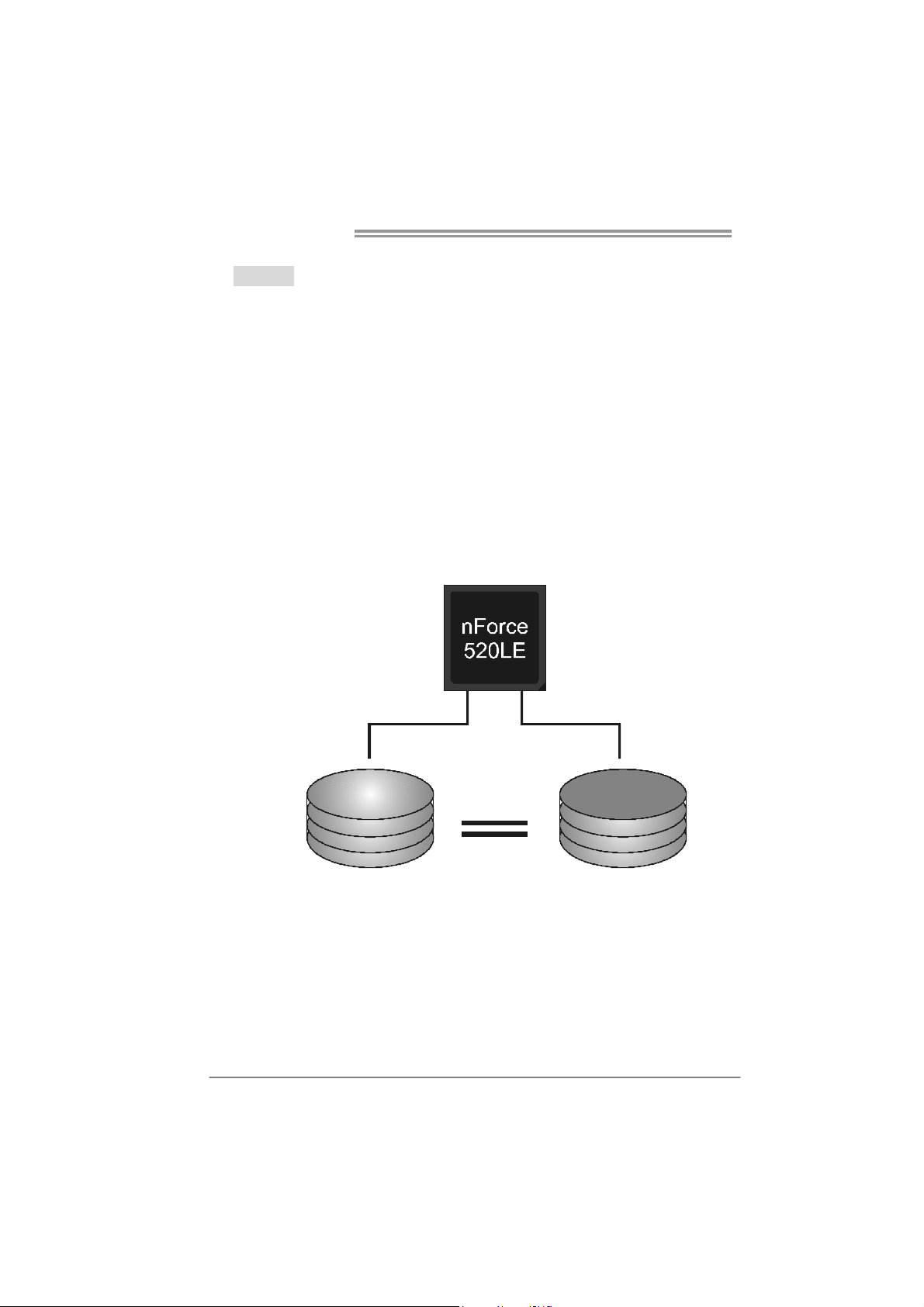
CHAPTER 4: NVIDIA RAID FUNCTIONS
NF520B A2G+
4.1 O
z Supports Windows XP Home/Professional Edition, and Windows 2000 Professional.
PERATING SYSTEM
4.2 RAID ARRAYS
NVRAID supports the following types of RAID arrays:
RAID 0: RAID 0 defines a disk striping scheme that improves disk read and write times for
many applications.
RAID 1: RAID 1 defines techniques for mirroring data.
4.3 HOW RAID WORKS
RAID 0:
The controller “stripes” data across multiple drives in a RAID 0 array system. It breaks
up a large f i le into sma ller blocks an d pe rfo rms disk r ead s and writes acr oss multip le
drives in parallel. The size of each block is determined by the stripe size parameter,
which you set during the creation of the RAID set based on the system environment. This
technique reduces overall disk access time and offers high bandwidth.
Features and Benefits
Drives: Minimum 1, and maximum is up to 6 or 8. Depending on the
platform.
Uses: Intended for non-critical data requiring high data throughput, or any
environment that does not require fault tolerance.
Benefits: provides increased data throughput, especially for large files. No
capacity loss penalty for parity.
Drawbacks: Does not deliver any fault tolerance. If any drive in the array
fails, all data is lost.
Fault Tolerance: No.
Blo ck 1
Block 3
Block 5
Block 2
Block 4
Block 6
17
Page 20
Motherboard Manual
RAID 1:
Every read and write is actually carried out in parallel across 2 disk drives in a RAID 1
array system. The mirrored (backup) copy of the data can reside on the same disk or on a
second redundant drive in the array. RAID 1 provides a hot-standby copy of data if the
active volume or drive is corrupted or becomes unavailable because of a hardware failure.
RAID techniques can be applied for high-availability solutions, or as a form of automatic
backup that eliminates tedious manual backups to more expensive and less reliable
media.
Features and Benefits
Drives: Minimum 2, and maximum is 2.
Uses: RAID 1 is ideal for small databases or any other application that
requires fault tolerance and minimal capacity.
Benefits: Provides 100% data redundancy. Should one drive fail, the
controller switches to the other drive.
Drawbacks: Requires 2 drives for the storage space of one drive.
Performance is impaired during drive rebuilds.
Fault Tolerance: Yes.
18
Block 1
Block 2
Block 3
Block 1
Block 2
Block 3
Page 21

CHAPTER 5: USEFUL HELP
NF520B A2G+
5.1 D
RIVER INSTALLATION NOTE
After you installed your operating system, please insert the Fully Setup
Driver CD into your optical drive and install the driver for better system
performance.
You will see the following window after you insert the CD
The setup guide will auto detect your motherboard and operating system.
Note:
If this window did n’t show up after you insert the Driver CD, please use file browser to
locate and execute the file SETUP.EXE under your optical drive.
A. Driver Installation
To install the driver, please click on the Driver icon. The setup guide will
list the compatible driver for your motherboard and operating system.
Click on each device driver to launch the installation program.
B. Software Installation
To install the software, please click on the Software icon. The setup guide
will list the software available for your system, click on each software title
to launch the installation program.
C. Manual
Aside from the paperback manual, we also provide manual in the Driver
CD. Click on the Manual icon to browse for available manual.
Note:
You will need Acrobat Reader to open the manual file. Please download the latest version
of Acrobat Reader software from
http://www.adobe.com/products/acrobat/readstep2.html
19
Page 22

Motherboard Manual
5.2 SOFTWARE
Installing Software
1. Insert the Setup CD to the optical drive. The drivers installation program
would appear if the Autorun function has been enabled.
2. Select Software Installation, and then click on the respective software
title.
3. Follow the on-screen instructions to complete the installation.
BIOScreen Utility
This utility allows you to personalize your boot logo easily. You can choose
JPG or BMP as your boot logo so as to customize your computer.
Please follow the following instructions to update boo logo:
1. Load Image:Choose the picture as the boot logo.
2. Transform:Transform the picture for BIOS and preview the result.
3. Update Bios:Write the picture to BIOS Memory to complete the update.
20
Page 23
5.3 AWARD BIOS BEEP CODE
Beep Sound Meaning
One long beep followed by two short
beeps
High-low siren sound CPU overheated
One Short beep when system boot-up No error found during POST
Long beeps every other second No DRAM detected or install
Video card not found or video card
memory bad
System will shut down automatically
5.4 EXTRA INFORMATION
CPU Overheated
If the system shutdown automatically after power on system for
seconds, that means the CPU protection function has been activated.
When the CPU is over heated, the motherboard will shutdow n
automatically to avoid a damage of the CPU, and the system may not
power on again.
In this case, please double check:
1. The CPU cooler surface is placed evenly with the CPU surface.
2. CPU fan is rotated normally.
3. CPU fan speed is fulfilling with the CPU speed.
After confirmed, please follow steps below to relief the CPU protection
function.
1. Remove the power cord from power supply for seconds.
2. Wait for seconds.
3. Plug in the power cord and boot up the system.
Or you can:
1. Clear the CMOS data.
(See “Close CMOS Header: JCMOS1” section)
2. Wait for seconds.
3. Power on the system again.
NF520B A2G+
21
Page 24

Motherboard Manual
5.5 TROUBLESHOOTING
Probable Solution
1. There is no power in the system.
Power LED does not shine; the
fan of the power supply does not
work
2. Indicator light on keyboard does
not shine.
System is inoperative. Keyboard lights
are on, power indicator lights are lit,
and hard drives are running.
System does not boot from a hard disk
drive, but can be booted from optical
drive.
System only boots from an optical
drive. Hard disks can be read,
applications can be used, but system
fails to boot from a hard disk.
Screen message shows “Invalid
Configuration” or “CMOS Failure.”
System cannot boot after user installs a
second hard drive.
1. Make sure power cable is
securely plugged in.
2. Replace cable.
3. Contact technical support.
Using even pressure on both ends of
the DIMM, press down firmly until the
module snaps into place.
1. Check cable running from disk to
disk controller board. Make sure
both ends are securely plugged
in; check the drive type in the
standard CMOS setup.
2. Backing up the hard drive is
extremely important. All hard
disks are capable of breaking
down at any time.
1. Back up data and applications
files.
2. Reformat the hard drive.
Re-install applications and data
using backup disks.
Review system’s equipment. Make sure
correct information is in setup.
1. Set master/slave jumpers
correctly.
2. Run SETUP program and select
correct drive types. Call the drive
manufacturers for compatibility
with other drives.
22
Page 25

NF520B A2G+
This page is intentionally left blank.
23
Page 26

Motherboard Manual
APPENDIX: SPEC IN OTHER LANGUAGES
G
ERMAN
Sp ezif ika tio nen
Sockel AM2+
CPU
FSB
Chipsatz
Super E/A
Arbeitsspeiche
r
IDE
AMD Athlon 64 / Athlon 64 FX / Althlon 64
X2 / Sempron / Phenom / Pheno m II
Prozessoren
(Maximales Watt: 95W)
Unterstützt HyperTransport 2.0 mit einer
Bandbreite von bis zu 2.0 GT/s
nVIDIA nForce 520LE
ITE 8718
Biet et die h äufig ver wendeten a lten Super
E/A-Funktionen.
Low Pin Count-Schnittstelle
DDR2 DIMM-Steckplätze x 4
Jeder DIMM unterstützt 256MB/512MB/
1GB/2GB/4GB DDR2
Max. 16GB Arbeitsspeicher
Int eg r iert er IDE - C ontro lle r
Die AMD 64-Architektur unterstützt eine 32-B it- und
64-Bit-Datenverarbeitung
Unterstützt Hyper Transport und Cool’n’Quiet
Umgebungskontrolle,
Hardware-Überwachung
Lüfterdrehz ahl-Cont roller
"Smart Guardian"-Funktion von ITE
Dual-Kanal DDR2 Speichermodul
Unterstützt DDR2 533 / 667 / 800
Unterstützt DDR2 1066 (by AM2+ / AM3 CPU)
registrierte DIMMs. ECC DIMMs werden nicht
unterstützt.
Ultra DMA 33 / 66 / 100 / 133 Bus Master-Modus
Unterstützt PIO-Modus 0~4,
SATA II
LAN
Audio-Codec
Steckplätze
24
Integrierter Serial ATA-Controller
Datentransferrate b is zu 3Gb/s
Konform mit der SATA-Spezifikation Version 2.0.
10 / 100 / 1000 Mb/s Auto-Negotiation
Realtek RTL 8111DL
Halb-/ Vollduplex-Funktion
5.1-Kanal-Audioausgabe
ALC662
Unterstützt High-Definition Audio
PCI-Steckplat z x3
PCI Express x16 Steckplatz x1
PCI Express x 1-Steckplatz x1
Page 27

Onboard-Ansc
hluss
NF520B A2G+
Sp ezif ika tio nen
Diskettenlaufwerkanschluss x1 Jeder Anschluss unterstützt 2 Diskettenlaufwerke
Druckeranschluss Anschluss x1 Jeder Anschluss unterstützt 1 Druckeranschluss
IDE-Anschluss x1
SATA-Anschluss x2
Fronttafelanschluss x1
Front-Audioanschluss x1
CD-IN-Anschluss x1 Unterstützt die CD Audio-In-Funktion
S/PDIF- Ausgangsanschluss x1
CPU-Lüfter-Sockel x1
System-Lüfter-Sockel x1
"CMOS löschen "-So cke l x1
USB-Anschluss x2 Jeder Anschluss unterstützt 2
Stromanschluss (24-polig) x1
St r oman s chluss (4-pol ig ) x1
Jeder Anschluss unterstützt 2 IDE-Laufwerke
Jeder Anschluss unterstützt 1 SATA-Laufwerk
Unterstützt die Fronttafelfunktionen
Unterstützt die Fronttafel-Audioanschlussfunktion
CPU-Lüfterstromversorgungsanschluss (mit Smart
Fan -F un ktio n)
System-Lüfter-Stromversorgungsanschluss
Fronttafel-USB-Anschlüsse
Rückseiten-E/
A
Plat inengröße.
Sonderfunktio
nen
OS-Unterstütz
ung
PS/2-Tastatur x1
PS/2- Maus x1
Serieller Anschluss x1
LAN-Anschluss x1
USB-Anschluss x4
Audioanschluss x3
200 mm (B) X 293 mm (L)
Unterstützt RAID 0 / 1
Windows XP / Vista 32 / 64 / Windows 7
Biostar behält sich das Recht vor, ohne Ankündigung
die Unterstützung für ein Betriebssystem
hinzuzufügen oder zu entfernen.
25
Page 28

Motherboard Manual
FRENCH
Socket AM2+
SPEC
UC
Bus frontal
Chipset
Super E/S
Mémo ire
principale
IDE
Processeurs AMD Athlon 64 / Athlon 64 FX
/ Alth lon 64 X2 / S empron / Pheno m /
Pheno m II
(Wat t maximu m : 95W)
Prend en charge Hyper Transport 2.0
jusqu'à une bande passante de 2.0 GT/s
nVIDIA nForce 520LE
ITE 8718
Fournit la fonctionnalité de Super E/S
patrimoniales la plus utilisée.
Fentes DDR2 DIM M x 4
Chaque D IMM prend en charg e des DDR2
de 256Mo/512Mo/1Go/2Go/4Go
Capacité mé mo ire max i male de 16 Go
Contrôleur IDE intégré
L'architecture A MD 64 permet le calcul 32 et 64 bits
Prend en charge Hyper Transport et Cool’n’Qu iet
Int e rface à f aib le co mpte de b roches
Initiatives de contrôle environnementales,
Mon iteur d e mat ér iel
Contrôleur de vitesse de ventilateur
Fonction "Gardien intelligent" de l'ITE
Modu le d e mé mo ire DDR2 à mo d e à do uble vo ie
Prend en charge la DDR2 533 / 667 / 800
Prend en charge la DDR2 1066 (by AM2+ / AM3 CPU)
Les DIMM à registres et DIMM avec code correcteurs
d'erreurs ne sont pas prises en charge
Mode principale de Bus Ultra DMA 33 / 66 / 100 / 133
Prend en charge le mode PIO 0~4,
SATA II
LAN
Codec audio
Fentes
26
Contrô leur Serial ATA int é gr é
Realtek RTL 8111DL
ALC662
Fente PCI x3
Slot PCI Express x16 x1
Slot PCI Express x 1 x1
Taux de transfert jusqu'à 3 Go/s.
Co nforme à l a s p écificat ion SATA Ver s ion 2.0
10 / 100 / 1000 Mb /s négo ciat ion automatique
Half / Full duplex capability
Sortie audio à 5 .1 vo ies
Prise en ch arg e de l'audio haute déf in it ion
Page 29

Connecteur de disquette x1
Connecteur de Port d'imprimante x1 Chaque connector prend en charge 1 Port d'imprimante
Connecteur IDE x1
Connecteur SATA x2
Connecteur du panneau avant x1 Prend en charge les équipements du panneau avant
Connecteur Audio du panneau avant x1 Prend en charge la fonction audio du panneau avant
Connecteur
embarqu é
E/S du
panneau
arrière
Dimensions
de la carte
Fonctionnali
tés
spéciales
Support SE W indows XP / Vista 32 / 64 / Windows 7
Connecteur d'entrée CD x1 Prend en charge la fonction d'entr ée aud io de CD
Connecteur de sortie S/PDIF x1
Embase de ventilateur UC x1
Embase de ventilateur système x1 Alimentation électrique du ventilateur système
Embase d'effacement CMOS x1
Connecteur USB x2
Connecteur d'aliment at ion x 1
(24 broches)
Connecteur d'aliment at ion x 1
(4 broch es )
Clavier PS/2 x1
Souris PS/2 x1
Port série x1
Port LAN x1
Port US B x4
Fiche audio (Ver 5.x) x6
Fiche audio (Ver 6.x) x3
200 mm (l) X 293 mm (H)
Prise en charg e RAID 0 / 1
NF520B A2G+
SPEC
Chaque connect or prend en ch arg e 2 lecteurs de
disquettes
Chaque connecteur pr end en ch arg e 2 périp hér iqu es
IDE
Chaque connecteur pr end en ch arg e 1 périp hér iqu e
SATA
Alimentation électrique du ventilateur UC (avec
fonction de ventilateur intelligent)
Chaque connecteur prend en charge 2 ports USB de
panneau avant
Biostar se réserve le droit d'ajouter ou de supprimer le
support de SE avec ou sans préavis.
27
Page 30

Motherboard Manual
ITALIAN
Socket AM2+
SPECIFICA
CPU
FSB
Chipset
Super I/O
Memoria
principale
IDE
Processori AMD Athlon 64 / Athlon 64 FX
/ A lth lo n 64 X2 / Sempron / P h eno m /
Pheno m II
(Watt massimo: 95W)
Supporto di HyperTransport 2.0 fino a
2.0 GT/s di larghezza di banda
nVIDIA nForce 520LE
ITE 8718
Fo rnis ce le f unz ionalità legacy Su per
I/O usate più comunemente.
Interfaccia LPC (Low Pin Count)
Alloggi DIMM DDR2 x 4
Ciascun DIMM supporta DDR2
256MB/512MB/1GB/2GB/4GB
Capacità massima della memoria
16GB
Co n troller IDE int eg rat o
L’archit ett u ra AMD 64 abilita la co mpu taz io ne 32
e 64 bit
Supporto di Hyper Transport e Cool’n’Quiet
Funzioni di controllo dell’ambiente:
Monitoraggio hardware
Co ntroller velo c it à ventolin a
Funzione "Smart Guardian" di ITE
Modulo di memoria DDR2 a canale doppio
Supporto di DDR2 533 / 667 / 800
Supporto di DDR2 1066 (by AM2+ / A M3 CPU)
DIMM registrati e DIMM ECC non sono supportati
Modalità Bus Master Ultra DMA 33 / 66 / 10 0 / 133
Supporto modalità PIO Mode 0-4
SATA II
LAN
Codec
audio
Allo g g i
28
Co ntroller Ser ia l ATA in t eg rato
Velocità di trasferimento dei dati fino a 3 Gb/s.
Co mp at ib ile s p ec if iche S ATA Vers ione 2.0 .
Negoziazione automatica 10 / 100 / 1000 Mb/s
Realtek RTL 8111DL
Capacità Half / Full Duplex
Uscita audio 5.1 canali
ALC662
Supporto audio High-Definition (HD)
Allo g g io PC I x3
Alloggio PCI Express x16 x1
Alloggio PCI Express x1 x1
Page 31

Connettori
su scheda
I/O
pannello
posteriore
Dimension
i scheda
Caratterist
iche
speciali
Sistemi
operativi
supportati
NF520B A2G+
SPECIFICA
Connettore floppy x1 Ciascun connettore supporta 2 unità Floppy
Connettore Porta stampante x1 Ciascun connettore supporta 1 Porta stampante
Connettore IDE x1
Connettore SATA x2
Connettore pannello frontale x1
Connettore audio frontale x1
Connettore CD-in x1
Connettore output SPDIF x1
Co lletto r e ventolina C PU x1
Co lletto r e ventolina sistema x 1
Co lletto r e cance llaz ion e C MOS x 1
Connettore USB x2
Connettore alimentaz ione x1
(24 pin)
Connettore alimentaz ione x1
(4 pin)
Tas t iera PS /2 x 1
Mou s e PS/2 x 1
Porta seriale x1
Porta LAN x1
Porta USB x 4
Connettore audio x3
200 mm (larghezza) x 293 mm
(altez za)
Supporto RAID 0 / 1
Windows XP / Vista 32 / 64 / Windows
7
Ciascun connettore supporta 2 unità IDE
Ciascun connettore supporta 1 unità SATA
Su pporta i serviz i d e l panne l lo fro n tale
Supporta la funzione audio pannello frontale
Su pporta la fun z io ne input au dio CD
Alimentazione ventolina CPU (con funzione Smart
Fan)
Alimentazione ventolina d i sistema
Ciascun connettore supporta 2 porte USB
pannello frontale
Biostar si riserva il diritto di aggiungere o
rimuovere il supporto di qualsiasi sistema
operativo senza preavviso.
29
Page 32
Motherboard Manual
SPANISH
Conector AM2+
Procesadores AMD Athlon 64 / Athlon 64
CPU
FSB
Conjunto de
chips
Súper E/S
Memoria
principal
IDE
SATA II
Red Local
Códecs de
sonido
Ranuras
FX / Athlon 64 X2 / Sempron / Pheno m /
Phenom II
(Vatio máx imo: 95W )
Admite HyperTransport 2.0 con un ancho
de banda de hasta 2.0 GT/s
nVIDIA nForce 520LE
ITE 8718
Le ofrece las funcionalidades heredadas de
us o más comú n Súper E /S.
Ranuras DIMM DDR2 x 4
Cada DIMM admite DDR de 256MB/
512MB/1GB/2GB/4GB
Capacidad máxima de memoria de 16GB
Controlador IDE integrado
Controlador ATA Serie Integrado
Realtek RTL 8111DL
ALC662
Ranura PCI X3
Ranura PCI Express x16 X1
Ranura PCI express x 1 X1
Especificación
La arquitectura AMD 64 permite el procesado de 32 y
64 bits
Soporta las tecnologías Hyper Transport y
Interfaz de cuenta Low Pin
In iciat ivas d e cont rol d e entorno,
Monitor hardware
Controlador de velocidad de ventilador
Función "Guardia inteligente" de ITE
Módulo de memoria DDR2 de canal Doble
Admite DDR2 de 533 / 667 / 800
Admite DDR2 de 1066 (by AM2+ / AM3 CPU)
No admite DIMM registrados o DIMM compatibles con
ECC
Modo bus maestro Ultra DMA 33 / 66 / 100 / 133
Soporte los Modos PIO 0~4,
Tasas de transferencia de hasta 3 Gb/s.
Co mp at ible co n la ve rsión S ATA 2 .0.
Negociación de 10 / 100 / 1000 Mb/s
Funciones Half / Full dúplex
Salida de sonido de 5.1 canales
Soporte de sonido de Alta Definición
30
Page 33

Conectores
en p laca
Panel
trasero de
E/S
Ta maño d e
la placa
NF520B A2G+
Especificación
Conector disco flexible X1 Cada conector soporta 2 unidades de disco flexible
Conector Puerto de impresora X1 Cada conector soporta 1 Puerto de impresora
Conector IDE X1
Conector SATA X2
Conector de panel frontal X1
Conector de sonido frontal X1
Conector de entrada de CD X1
Conector de salida S/PDIF X1
Cabecera de ventilador de CPU X1
Cabecera de ventilador de sistema X1
Cabecera de borrado de CMOS X1
Conector USB X2 Cada conector s oporta 2 puertos USB frontales
Conector de alimentación X1
(24 patillas)
Conector de alimentación X1
(4 patillas)
Tec lad o P S /2 X 1
Ratón PS/2 X1
Puert o serie X1
Puerto de red local X1
Puert o USB X4
Conector de sonido X3
200 mm. (A) X 293 mm. (H)
Cada conector soporta 2 dispositivos IDE
Cada conector soporta 1 dispositivos SATA
So p o rta instalaciones en e l pan e l fro ntal
Soporta funciones de sonido en el panel frontal
Soporta función de entrada de sonido de CD
Fuente de alimentación de ventilador de CPU (con
función Smart Fan)
Fuente de alimentación de ventilador de sistema
Funciones
especiales
Soporte de
sistema
operativo
Admite RAID 0 / 1
Windows XP / Vista 32 / 64 / Windows 7
Biostar se reserva el derecho de añadir o retirar el
soporte de cualquier SO con o sin aviso previo.
31
Page 34

Motherboard Manual
PORTUGUESE
Socket AM2+
Processadores AMD Athlon 64 / Athlon 64 FX
CPU
FSB
Chipset
Especificaçã
o Super I/O
Memória
principal
IDE
SATA II
LAN
Codec de
som
Ranhuras
/ Alth lon 64 X2 / S empron / Pheno m /
Pheno m II
(Watt máximo: 95W)
Suport a a tecno logia HyperTransport 2.0 com
uma largura de banda até 2.0 GT/s
nVIDIA nForce 520LE
ITE 8718
Proporciona as funcionalidades mais
utilizadas em termos da especificação Super
I/O.
Ranhuras DIMM DDR2 x 4
Cada módulo DIMM suporta uma memória
DDR2 de 256MB/512 MB/ 1GB/2GB/4GB
Capacidad e máx ima de memór ia: 16GB
Controlador IDE integrado
Controlador Serial ATA integrado
Realtek RTL 8111DL
ALC662
Ranhura PCI x3
Ranhura PCI Express x16 x1
Ranhura PCI Express x 1 x1
ESPECIFICAÇÕES
A arquit ectura AMD 64 per mite uma co mputa ção de
32 e 64 bits
Suporta as tecno logias Hype r Transport e
Cool’n’Quiet
Interface LPC (Low Pin Count).
In iciat ivas p ara con t ro lo d o a mb iente
Monitorização do hardware
Controlador da velocidade da ventoinha
Função "S mart Gu ardian" d a ITE
Módulo de memória DDR2 de canal duplo
Suporta módulos DDR2 533 / 667 / 800
Suporta módu los DDR2 1066 (by A M2+ / AM3 CP U)
Os módulos DIMM registados e os DIMM ECC não
são suportados
Modo Bus master U ltra DMA 33 / 66 / 100 / 133
Suporta o modo PIO 0~4,
Velocidades de transmissão de dados até 3 Gb/s.
Compat ib ilidad e co m a especificação SATA versão
2.0.
Auto negociação de 10 / 100 / 1000 Mb/s
Capacidade semi/full-duplex
Saída de áudio de 5.1 canais
Suporta a especificação High-Definition Audio
32
Page 35

Conectores
na placa
Entradas/S
aídas no
painel
traseiro
Tamanho
da placa
Característi
cas
especiais
Sistemas
operativos
suportados
NF520B A2G+
ESPECIFICAÇÕES
Conector da unidade de disquetes x1 Cada conector suporta 2 unidades de disquetes
Conector da para impressora x1 Cada conector suporta 1 Porta para impressora
Conector IDE x1 Cada conector suporta 2 dispositivos IDE
Conector SATA x2 Cada conector suporta 1 dispositivo SATA
Conector do painel frontal x1 Para suporte de várias funções no painel frontal
Conector de áud io frontal x1 Sup orta a fun ção de áudio no painel fronta l
Conector par a ent r ada d e CDs x1 Suporta a entrada d e áud io a part ir de CDs
Conector de saída S/PDIF x1
Conector da ventoinha da CPU x1
Conector da ventoinha do sistema x1 Alimentação da ventoinha do s istema
Conector para limpeza do CMOS x1
Conector USB x2
Conector de alimentação x1
(24 pinos)
Conector de alimentação x1
(4 p inos)
Tec lad o P S /2 x 1
Rato PS/2 x1
Porta s ér ie x1
Porta LAN x1
Porta USB x 4
Tomada de áudio x3
200 mm (L) X 293 mm (A)
Suporta as funçõ es RA ID 0 / 1
Windows XP / Vista 32 / 64 / Windows 7
Alimentação da ventoinha da CPU (com a função
Smart Fan)
Cada conector suporta 2 portas USB no painel
frontal
A Biostar reserva-se o direito de adicionar ou
remover suporte para qualquer sistema operativo
com ou sem avis o prév io.
33
Page 36

Motherboard Manual
j
POLISH
Socket AM2+
SPEC
Procesor
FSB
Chipset
Pamięć
główna
Super I/O
IDE
AMD Athlon 64 / Athlon 64 FX / Althlon 64
X2 / Sempron / Phenom / Pheno m II
Procesory
(Maksymalny Watt: 95W)
Obsługa HyperTransport 2.0 o szerokości
pasma do 2.0 GT/s
nVIDIA nForce 520LE
Gniazda DDR2 DIMM x 4
Każde gniazdo DIMM obsługuje moduły
256MB/512MB/1GB/2GB/4GB DDR2
Maks. wielkość pamięci 16GB
ITE 8718
Zapewnia na
Super I/O.
Zintegrowany kontroler IDE
bardz iej powszechne funkcje
Architektura AMD 64 umożliwia przetwarzanie 32 i 64
bitowe
Obsługa Hyper Transport oraz Cool’n’Quiet
Mod uł pamięci DDR2 z trybem podwójnego kanału
Obsługa DDR2 533 / 667 / 800
Obsługa DDR2 1066 (by AM2+ / AM3 CPU)
Brak obsług i R egister ed DIMM oraz ECC D IMM
Interfejs Low Pin Count
Funkcje kontroli warunków pracy,
Mon itor H /W
Kontroler prędkości wentylatora
Funkcja ITE "Smart Guardian"
Ultra DMA 33 / 66 / 100 / 133 Tryb Bus Master
obsługa PIO tryb 0~4,
SATA II
LAN
Kodek
dźwiękow y
Gniazda
34
Zintegrowany kontroler Serial ATA
Transfer danych do 3 Gb/s.
Zgodność ze specyfikacją SATA w wersji 2.0.
10 / 100 / 1000 Mb/s z automatyczną negocjacją sz ybkości
Realtek RTL 8111DL
Działanie w tryb ie połowicznego / pełnego dupleksu
5.1 kanałowe wyjście audio
ALC662
Obsługa H ig h-Def in it io n Aud io
Gniazdo PCI x3
Gniazdo PCI Express x16 x1
Gniazdo PCI Express x 1 x1
Page 37

Złącza
wbud owane
Back Panel
I/O
Wymiary
płyty
NF520B A2G+
SPEC
Złącze napędu dyskietek x1 Każde złącze obs ługuje 2 napędy dyskietek
Złącze Port drukarki x1 Każde złącze o bs ługuje 1 Port drukarki
Złącze IDE x1
Złącze SATA x2
Złącze panela przedniego x1
Przedn ie złącze aud io x1
Złącze wejścia CD x1
Złącze wyjścia S/PDIF x1
Złącze główkowe wentylatora procesora
Złącze głó wkowe wenty latora
systemowego x1
Złącze głó wkow e kasowania C MOS x1
Złącze USB x2 Każde złą cze obsługuje 2 porty USB na panelu przednim
Złącze zas ilania (24 pinowe) x1
Złącze zas ilania (4 p ino we) x1
Klawiatura PS/2 x1
Mys z PS /2 x1
Port szeregowy x1
Port LAN x1
Port US B x4
Gniazdo audio x3
200 mm (S) X 293 mm (W)
Każde złącze obsługuje 2 urządzenia IDE
Każde złącze obsługuje 1 urządzenie SATA
Obsługa elementów panela przedniego
Obsługa funkcji audio na panelu przednim
Obsługa funkcji wejścia aud io CD
Zasilanie wentylatora procesora (z funkcją Smart Fan)
x1
Zasilanie wentylatora systemowego
Funkcje
specjalne
Obsluga
systemu
operacyjne
go
Obsługa RAID 0 / 1
Windows XP / Vista 32 / 64 / Windows 7
Biostar zastrzega sobie prawo dodawania lub
odwoływan ia obsług i dowo lnego systemu operacyjnego
bez powiadomienia.
35
Page 38
Motherboard Manual
RUSSIAN
CPU
(центральн
ый
процессор)
FSB
Набо р
микросхем
Основная
память
Super I/O
IDE Встроенное устройство упр авл ения
SATA Встроенное последовательное устройство
Локальная
сеть
Звуко во й
кодек
Слоты
Гнездо AM2+
Процессоры AMD Athlon 64 / Athlon 64 FX /
Althlon 64 X2 / Sempron / Phenom / Phenom
II
(Максим ал ьн ый ватт: 95W )
Поддержка HyperTransport 2.0 с
пропускной способностью до 2.0 GT/s
nVIDIA nForce 520LE
Слоты DDR2 DIMM x 4
Каждый модуль DIMM поддерживает
256МБ /512МБ /1 ГБ/2ГБ/4ГБ DDR2
Максимальная ёмкость памяти 16 ГБ
ITE 8718
Обеспечивает наиболее используемые
действующие фун кцио нальн ы е
возможности Super I/O.
Realtek RTL 8111DL
ALC662
Слот PCI x3
Слот PCI Express x16 x1
Слот PCI Express x 1 x1
СПЕЦ
Арх итектур а A MD 64 разрешать обработка данных
на 32 и 64 бит
Поддержка Hyp er Transpo rt и Cool’n’Quiet
Мод уль памяти с двухканальн ым режимом DDR2
Поддержка DDR2 533 / 667 / 800
Поддержка DDR2 1066 (by AM2+ / AM3 CPU)
Не поддерживает зарегистрированные модули
DIMM and ECC DIMM
Интерфейс с низким количеством выводов
Инициативы по охране окружающей среды,
Аппаратный монитор
Регул ятор скорости
Функц ия ITE "Smart Guard ian " (Интеллектуальная
защит а)
встроенными интерфейсами устройств
Режим "хозяина" шины Ultra D MA 3 3 / 66 / 1 00 /
133
Поддержка режима PIO 0~4,
упра вления ATA
скорость передачи д анных до 3 гигабит/с.
Соответствие спецификации SATA версия 2.0.
Автоматическо е со гласован ие 10 / 100 / 1000 Мб/с
Частичная / полна я дуплексная способность
Звуко ва я поддержка High- Def in it io n
5.1канальный звуковой вых од
36
Page 39

Встроенны
й разъём
Задняя
панель
средств
ввода-выв
ода
Разм ер
панели
Специальн
ые
технически
е
характерис
тики
Поддержка
OS
NF520B A2G+
СПЕЦ
Разъ ём НГМ Д x1
Разъ ём Пор т подклю чения принтера x1
Разъ ём IDE x 1
Разъ ём SATA x2 Каждый разъём поддерживает 1 устройство SATA
Разъ ём на лицевой панели x1 Поддержка устро йств на лицевой панели
Входной звуковой разъём x1 Поддержка звуковых функций на лицевой панели
Разъ ём ввода для CD x1 Поддержка функции ввода для CD
Разъ ём вывода для S/PDIF x1
Контактирующее приспособление
вентил ятора центрального процессора x1
Контактирующее приспособление
вентил ятора системы x1
Открытое контактир ующ ее
приспособление CMOS x1
USB- разъём x2
Разъ ем питания (24 вы во д) x1
Разъ ем питания (4 вы вод) x1
Клавиатура PS/2 x1
Мышь PS/2 x1
Последоват ельны й порт x1
Пор т LAN x1
USB- порт x4
Гнездо для подключения
наушников x3
200 мм (Ш) X 29 3 мм (В)
Поддержка RAID 0 / 1
Windows XP / Vista 32 / 64 / Windows 7
Каждый разъём поддерживает 2 накопителя на
гибких магнитных дисках
Каждый разъём поддерживает 1 Порт
подключения принтера
Каждый разъём поддерживает 2 встроенных
интерфейса накопителей
Источник питания для вентил ято р а центрального
процессора (с фун кц ией интеллектуального
вентил ятора)
Источник питания для вентил ято р а системы
Каждый разъём поддерживает 2 USB-порта на
лицевой панели
Biostar сохраняет за собой право добавлять или
удаля ть средства обеспечения для OS с или без
предварительного уведомле ния.
37
Page 40

Motherboard Manual
ARABIC
تﺎﻔﺻاﻮﻤﻟا
ﺲﺒﻘﻣAM2+
ﻦﻜﻤﺗ ﺔﻴﻨﻘﺗ AMD 64 ءاﺮﺝإ تﺎﻴﻠﻤﻌﻟا ﺔﻴﺑﻮﺳﺎﺤﻟ ا ﺔﻋﺮﺴﺑ 32 و64 ﺖﺑ
ﻢﻋﺪﺗ ﺔﻴﻨﻘﺗ Hyper Transport و Cool’n’Quiet
ةﺪﺣو ةﺮآاذ DDR2 ﺔﺝودﺰﻡ ﻘﻟاةﺎﻨ
ﻢﻋﺪﺗ ةﺮآاﺬﻟا ﻦﻡ عﻮﻥ DDR2 تﺎﻌﺳ 533 / 667 / 800 ﺎﺠ ﻴﻡ ﺖﻳﺎﺑ
ﻢﻋﺪﺗ ةﺮآاﺬﻟا ﻦﻡ عﻮﻥ DDR2 تﺎﻌﺳ 1066 ﺎﺠﻴﻡ ﺖﻳﺎﺑ
(DDR2 1066 is by AM2+ / AM3 CPU)
ﻻ ﻢﻋﺪﺗ ﻖﺋﺎﻗر ةﺮآاﺬﻟا DIMM ﻚﻠﺗو ﻲﺘﻟا ﻻ اﻮﺘﺗﻖﻓ ﻊﻡ ECC
ﺔﻔﻴﻇو"S mart Gu ard ian" ﻦﻡ IT E
ﺔﻴﻨﻘ ﺘﺑ ﻞﻗﺎﻥUltra DMA 33 / 66 / 100 / 133
ﻊﺿو ﻢﻋدPIO Mode 0~4
ﺔﻘﺑﺎﻄﻡ تﺎﻔﺻاﻮﻤﻟ SATA راﺪﺻﻹا 2.0.
5.1 تاﻮﻨﻗ جﺮﺨﻟ تﻮﺼﻟا
تﺎﺠﻟﺎﻌ ﻣAMD Athlon 64 / Athlon 64 FX /
Sempron / Phenom / Phenom II /
(طاو ىﻮﺼﻗ: 95و)
ﻢﻋﺪﺗ ﺔﻴﻨ ﻘﺗ HyperTransport ددﺮﺘﺑ ﻞﺼ ﻳ ﻰﻟإ2.0 2.0
nVIDIA nForce 520LE
ﻢﻋﺪﺗ ﻞآ ﺔﺤﺘﻓ DIMM ﻢﻋﺪﺗ ةﺮآاذ ﻦﻡ عﻮﻥ DDR2 ﺔﻌﺳ
256/512 ﺎﺠﻴﻡ ﺖﻳﺎﺑ و1/ و2/ و4 ﺎﺠﻴﺝ ﺖﻳﺎﺑ
ﻞﺋﺎﺳو ﻢﻜﺤﺘﻟا ﻲﻓ ﺔﺌﻴﺒﻟا:
ﺐﻗاﺮﻡ ﺔﻓﺮﻌﻤﻟ ﺔﻟ ﺎﺣ ةﺰﻬﺝﻷا
ﺐﻗاﺮﻡ ﻲﻓ ﺔﻋﺮﺳ ﺔﺣوﺮﻤﻟا
ﻊﺿو ﻲﺴﻴﺋر
ﻞﻘﻥ تﺎﻥﺎﻴﺒﻟا تﺎﻋﺮﺴﺑ ﻞﺼﺗ ﻰﻟإ 3 ﺖﺑﺎﺠﻴﺝ/ﺔﻴﻥﺎﺙ.
ضوﺎﻔﺗ ﻲﺋﺎﻘﻠﺗ 10/100 ﺎﺠﻴﻣ ﺖیﺎﺑ /ﺔﻴﻥﺎ ﺛ و1ﺎﺠﻴﺝ ﺖﺑ/ﺔﻴﻥﺎﺛ
ﻴﻥﺎﻜﻡإﻞﻡﺎﻜﻟا جودﺰﻤﻟا ﻞﻘﻨﻟا ﺔ/ﻲﻔﺼﻨﻟا
5.1 تاﻮﻨﻗ جﺮﺨﻟ تﻮﺼﻟا
ﺮﻓﻮﺗ ﺔﻔﻴﻇو Super I/O ﺮﺜآﻷا ًﺎ ﻡ ا ﺪ ﺨ ﺘ ﺳا.
ﺗﻢﻋﺪ ﺔﻴﻨﻘ ﺗ Low Pin Count Interface
ﻢﻜﺤﺘﻡ Serial ATA ﻞﻡﺎﻜﺘﻡ
Realtek RTL 8111DL
Althlon 64 X2
GT/s
ﺔﺤﺘﻓDDR2 DIM M دﺪﻋ4
ITE 8718
ﻢﻜﺤﺘﻡ IDE ﻞﻡﺎﻜﺘﻡ
ALC662
ﺔﺤﺘﻓPCI دﺪﻋ3
ﺔﺤﺘﻓx16 PCI Express دﺪﻋ1
ﺔﺤﺘﻓPCI Express x 1 دﺪﻋ1
ةﺪﺣو ﺔﺠﻟﺎﻌﻤﻟا
ﺔﻳﺰآﺮﻤﻟا
ﻞﻗﺎﻨﻟا ﻲﻡﺎﻡﻷا ﻲﺒﻥﺎﺠﻟا
ﺔﻋﻮﻤﺠﻡ ﺢﺋاﺮﺸﻟا
ةﺮآاﺬﻟا ﺔﻴﺴﻴﺋﺮﻟا
ﺔﻌﺳ ةﺮآاذ ىﻮﺼﻗ 16 ﺎﺠﻴﺝ ﺖﻳﺎﺑ
Super I/O
ﺬﻔﻨﻣ IDE
SATA II
ﺔﻜﺒﺵ ﺔﻴﻠﺥاد
ﻚﻳدﻮآ تﻮﺼﻟا
تﺎﺤﺘﻔﻟا
38
Page 41

ﻆﻔﺘﺤﺗ Biostar ﺎﻬﻘﺤﺑ ﻲﻓ ﺔﻓﺎﺿإ وأ ﺔﻟازإ ﻢﻋﺪﻟا يﻷ مﺎﻈﻥ ﻞﻴﻐﺸﺗ رﺎﻄﺥﺈﺑ وأ نوﺪﺑ
ﺔﻥﺮﻤﻟا صاﺮﻗﻸﻟ ﻦﻴآﺮﺤﻡ ﻢﻋﺪﻳ
ﻲﺘﺤﺘﻓ ﺬﻔﻨﻡ ﻞآ ﻢﻋﺪﻳUSBﺔﻴﻡﺎﻡﻷا ﺔﺣﻮﻠﻟﺎﺑ
ةﺰﻬﺝأ ﻦﻡ ﻦﻴﻨﺙا ﺬﻔﻨﻡ ﻞآ ﻢﻋﺪﻳIDE
ةﺰﻬﺝأ ﻦﻡ ﺪﺣاو ﺬﻔﻨﻡ ﻞآ ﻢﻋﺪﻳSATA
ﺔﻴﻡﺎﻡﻷا ﺔﺣﻮﻠﻟا تاﺰﻴﻬﺠﺗ ﻢﻋﺪﻳ
تﻮﺼﻟا ﺔﻔﻴﻇو ﻢﻋﺪﻳﺔﻴﻡﺎﻡﻷا ﺔﺣﻮﻠﻟ ﺎﺑ
ﺞﻡﺪﻤﻟا صﺮﻘﻟا تﻮﺻ ﻞﺥد ﺔﻔﻴﻇ و ﻢﻋﺪﻳ
ﺔﻔﻴﻇو ﻊﻡ ﺔﺠﻟﺎﻌﻤﻟا ةﺪﺣو ﺔﺣوﺮﻤﻟ ﺔﻗﺎﻄﻟا ﻞﻴﺻﻮﺘﻟSmart Fan
مﺎﻈﻨﻟا ﺔﺣوﺮﻤﻟ ﺔﻗﺎﻄ ﻟا ﻞﻴﺻﻮﺘﻟ
ﻲﺘﺤﺘﻓ ﺬﻔﻨﻡ ﻞآ ﻢﻋﺪﻳUSBﺔﻴﻡﺎﻡﻷا ﺔﺣﻮﻠﻟﺎﺑ
رﺎﻄﺥإ.
تﺎﻔﺻاﻮﻤﻟا
ﺔﻥﺮﻡ صاﺮﻗأ كﺮﺤﻡ ﺬﻔﻨﻡ دﺪﻋ1
ﺔﻳﺰآﺮﻤﻟا ﺔﺠﻟﺎﻌﻤﻟا ةﺪﺣو ﺔﺣوﺮﻡ ﺔﻠﺻو دﺪﻋ1
ﺔﻴﻠﺤﻡ لﺎﺼﺗا ﺔﻜﺒﺵ ﺬﻔﻨﻡ دﺪﻋ1
Windows XP / Vista 32 / 64 / Windows 7
NF520B A2G+
ﺔﻌﺑﺎﻃ ﺬﻔﻨﻡ دﺪﻋ1
ﺔﻴﻡﺎﻡﻷا ﺔﺣﻮﻠﻟا ﺬﻔﻨﻡ دﺪﻋ1
ﻲﻡﺎﻡﻷا تﻮﺼﻟا ﺬﻔﻨﻡ دﺪﻋ1
جﺮﺥ ﺬﻔﻨﻡS/PDIF دﺪﻋ1
مﺎﻈﻨﻟا ﺔﺣوﺮﻡ ﺔﻠﺻو دﺪﻋ1
ﺢﺴﻡ ﺔﻠﺻوCMOS دﺪﻋ1
ﺔﻗﺎﻄﻟا ﻞﻴﺻﻮﺗ ﺬﻔﻨﻡ)24سﻮﺑد( دﺪﻋ1
ﺔﻗﺎﻄﻟا ﻞﻴﺻﻮﺗ ﺬﻔﻨﻡ)4ﺲﻴﺑﺎﺑد( دﺪﻋ1
ﺢﻴﺗﺎﻔﻡ ﺔﺣﻮﻟPS/2 دﺪﻋ1
سوﺎﻡ PS/2 دﺪﻋ1
ﻲﻠﺴﻠﺴﺗ ﺬﻔﻨﻡ دﺪﻋ1
ﺬﻓﺎﻨﻡUSB دﺪﻋ4
تﻮﺻ ﺲﺒﻘﻡ دﺪﻋ3
ﻢﻋﺪﺗ ﺔﻴﻨ ﻘﺗ RAID 0 / 1
200 ﻢﻡ)ضﺮﻋ (X 293 ﻢﻡ)عﺎﻔﺗرا(
ﺬﻔﻨﻡIDE دﺪﻋ1
ﺬﻔﻨﻡSATA دﺪﻋ2
ﺬﻔﻨﻡCD-IN دﺪﻋ1
ﺬﻓﺎﻨﻤﻟا ﻰﻠﻋ ﺢﻄﺳ
ﺔﺣﻮﻠﻟا
ﺬﻔﻨﻡUS B دﺪﻋ2
ﺬﻓﺎﻨﻡ ﻞﺥد/جﺮﺥ
ﺔﺣﻮﻠﻟا ﺔﻴﻔﻠﺨﻟا
ﺎﻳاﺰﻡ ﺔﺻ ﺎﺥ
ﻢﺠﺣ ﺔﺣﻮﻠﻟا
ﻢﻋد ﺔﻤﻈﻥأ ﻞﻴﻐﺸﺘﻟا
39
Page 42

Motherboard Manual
JAPANESE
Socket AM2+
AMD Athlon 64 / Athlon 64 FX / Althlon 64
CPU
X2 / Sempron / Phenom / Pheno m II プロ
セッサ
(最高 のワット : 95W)
仕様
AMD 64アーキ テクチ ャでは、32ビットと64ビット計算が可
能です
ハイパートラ ンス ポートとク ールアンド クワイ アットをサ ポ
ートします
FSB
チップセット
メインメモリ
Super I/O
IDE
SATA II
LAN
2.0 GT/sのバンド 幅まで ハイパート ランスポ
ート2.0をサポ ートします
nVIDIA nForce 520LE
DDR2 DIMMスロット x 4
各DIMMは 25 6 MB/512MB/1GB /2GB/4GB
DDR2をサポート
最大メモリ容 量16GB
ITE 8718
もっとも一般 に使 用されるレ ガシーSuper I/O
機能を採用し てい ます。
統合ID Eコントローラ
統合シリアルATA コントロー ラ
Realtek RTL 8111DL
デュアル チ ャン ネルモードDDR2メモリモジ ュール
DDR2 533 / 667 / 800をサポー ト
DDR2 1066 をサポート (by A M2+ / AM3 CPU)
登録済みDIMMとECC DIMMはサポート されません
低ピンカウン トイ ンターフェ イス
環境コントロ ール イニシアチ ブ、
H/Wモニ ター
ファン速度コ ント ローラ/ モニター
ITE の「スマート ガー ディアン」 機能
Ultra DMA 33 / 66 / 100 / 133バスマ スタ モード
PIO Mode 0~4のサポート 、
最高3 Gb/秒の データ転送 速度
SATAバージョン2.0仕様に準 拠。
10 / 100 / 1000 Mb/秒のオ ートネゴシ エーション
半/全二重機能
サウンド
Codec
スロット
40
ALC662
5.1チャンネル オーディオ アウ ト
ハイデフィニ ショ ンオーディ オのサポー ト
PCIスロット x3
PCI Express x16スロット x1
PCI Express x 1スロット x1
Page 43
オンボードコ
ネクタ
背面パネル
I/O
ボードサイズ
特殊機能
OSサポー ト
NF520B A2G+
仕様
フロッピーコ ネク タ x1 各コネクタは 2つのフロ ッピードラ イブを サポートし ます
プリンタポー トコ ネクタ x1 各コネクタは 1つのプリ ンタポート をサポート します
IDE コネクタ x1
SATAコネクタ x2
フロントパネ ルコ ネクタ x1
フロントオー ディ オコネクタ x1
CDインコネクタ x1
S/PDIFアウト コネクタ x1
CPUファンヘッダ x1
システムファ ンヘ ッダ x1
CMOSクリアヘッダ x1
USBコネク タ x2
電源コネクタ (24 ピン) x1
電源コネクタ (4ピン) x1
PS/2キーボード x1
PS/2マウス x1
シリアルポー ト x1
LANポート x1
USBポート x4
オーディオジ ャッ ク x3
200 mm (幅) X 293 mm (高さ )
RAID 0 / 1 のサ ポート
Windows XP / Vista 32 / 64 / Windows 7
各コネクタは 2つのIDE デバイスをサポ ートし ます
各コネクタは 1つのSATAデバイス をサポート します
フロントパネ ル機 能をサポー トします
フロントパネ ルオ ーディオ機 能をサポー トしま す
CDオーディオイ ン機 能をサポー トします
CPUファン電源装置(スマートファン 機能を搭載 )
システムファ ン電 源装置
各コネクタは 2つのフロ ントパネル USBポートをサ ポート し
ます
Biostarは事前の サポー トなしにOSサポー トを追加ま たは削
除する権利を 留保 します。
2009/09/18
41
 Loading...