

Page 1
CHROMATOGRAPHY SYSTEMS
NGC™ Fraction Collector Installation
Quick Guide
Installing the NGC Fraction Collector
Introduction
The NGC Fraction Collector provides versatile options for
preparative and analytical chromatography applications. The
high-capacity and flexible rack options enable fractions ranging
in size from milliliters to liters to be collected and accessed
freely during a purification run.
Setting Up the NGC Fraction Collector
This quick guide outlines the process of installing and plumbing
the NGC Fraction Collector to your NGC System. The fraction
collector (FC) can be installed on a laboratory bench or in a
coldroom or chromatography refrigerator.
1
Open the shipping box and remove the foam packaging.
Carefully lift the FC from the box. Do not lift the FC by the
gantry; reach down and lift it from the base. Grip the base
of the FC by the sides to lift from the shipping box.
Check the box for the tubing kit, external power supply,
and USB cable. The tubing kit contains:
92 cm green polyetheretherketone (PEEK) tubing
from NGC union to dispense head for F100 systems
(fittings on both ends)
92 cm orange PEEK tubing for F10 systems (fittings
on both ends)
92 cm clear fluorinated ethylene propylene (FEP)
waste line from dispense head to union (fittings on
both ends)
150 cm clear FEP waste line from union to waste
bottle (fitting on one end)
Black magnetic union to be attached to side of NGC
System to act as anchor point for FC tubing; position
as necessary to avoid kinking any of the tubes
Dispense head height adjustment
Dispense head cover
Standard racks
2
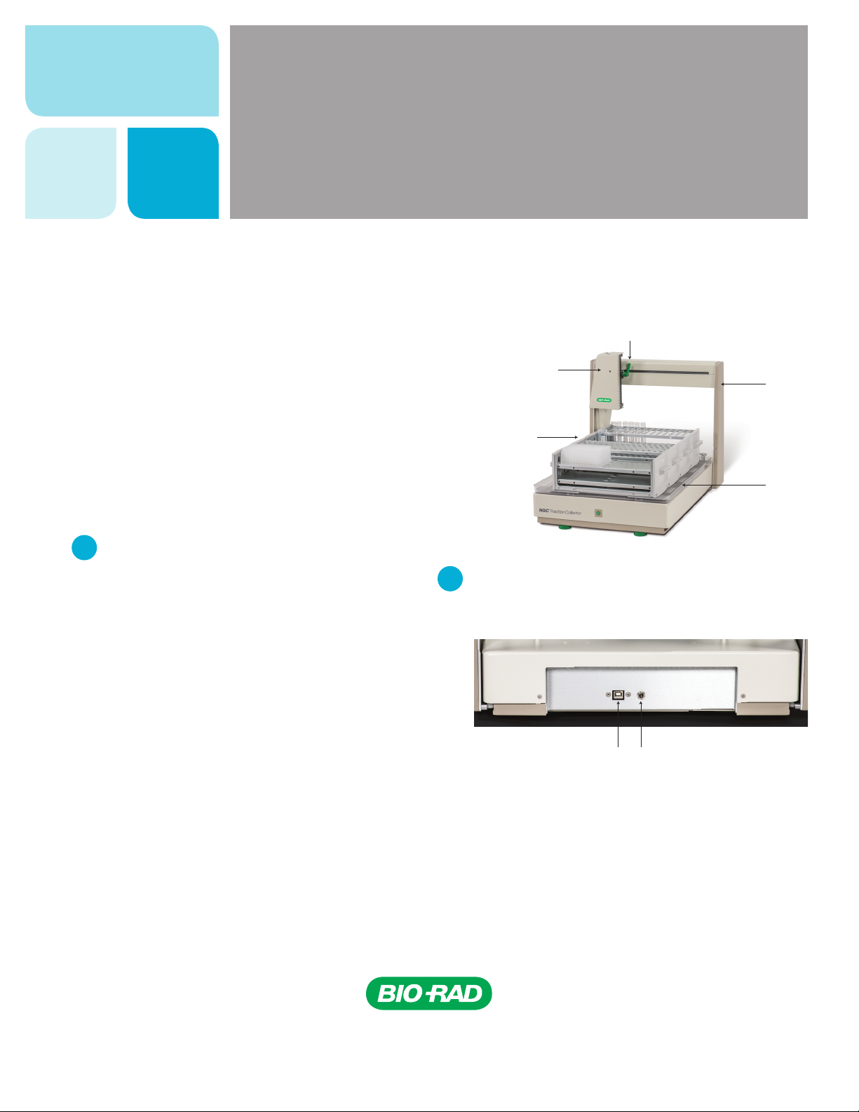
Connect the power cable and USB to the back of the FC.
Plug in the power supply and connect the USB cable into
a USB port on the NGC Chromatography System.
USB por t Power port
Gantry
Drip tray
Page 2
Plumbing the NGC Fraction Collector
Use the supplied tubing and union to plumb from the NGC System
to the dispense head on the fraction collector. Plumb the waste line
from the dispense head to the waste bottle via the union.
Rubbe r
grommet
Waste lin e
Sample tube
Cutout
Dispense head
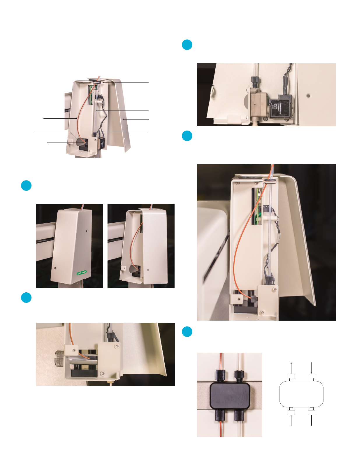
1
Open the dispense head cover using a small
Dispense head
cover
Dispense head
waste por t
Phillips screwdriver.
3
Attach the waste line from the dispense head waste port to
the union on the side of the NGC System.
4
Route both tubes through the top of the dispense head
cover by sliding them into the rubber grommet. Finally, close
the dispense head cover and fasten with the screw.
2
Connect the sample tube to the dispense head. Use the
cutout in the back of the cover to insert a fittings tightener
and tighten.
5
Attach the tubes to the union so the direction of flow is as
shown below.
To FC
inlet port
waste por t
From FC
From NGC
To waste
bottle
Page 3

Completing NGC Fraction Collector Installation
After plumbing the NGC Fraction Collector, complete the
installation and adjustments.
1
Place the plastic drip tray on the FC with the notched corner
facing the left rear of the FC platform.
4
The gantry and dispense head will move to the home
position when the NGC is powered up and the fraction
collector is detected by the system.
Note: The gantry will move quickly from the home position
to the first collection tube at the start of a run. Ensure there
are no objects in the way before starting collection.
2
Place the metal rack tray into position, ensuring it is aligned
correctly on the locating pins.
3
Turn on the fraction collector using the power button on
the front.
5
Place the racks on the FC, ensuring they are correctly
aligned on the raised locating pins. Identifier labels on the
racks should face right.
6
Before using the fraction collector, adjust the z-height of the
dispense head to sit within 10 mm of the collection vessels.
Page 4

Ordering Information
Catalog # Description
12 0 0 3748 Peltier Rack Power Supply, 4-channel power supply for up to
4 Peltier Rack Modules
12 0 0 3749 Peltier Rack Module, 1 insulated rack per module
120 0375 9 Insulated Rack for 50 ml Tubes, for 14 x 50 ml tubes
120 0 3751 Insulated Rack for 15 ml Tubes, for 30 x 15 ml tubes
12 0 0 3747 Peltier Rack Module Microtiter Plate Adaptor, for 2 deep well microtiter plates
120 0375 2 Rack for 13 mm Tubes, for 96 x 13 mm tubes
120 0375 5 Rack for 16 mm Tubes, for 75 x 16 mm tubes
120 0375 6 Rack for 18 mm/15 ml Tubes, for 70 x 18 mm tubes
120 0375 7 Rack for 50 ml Tubes, for 27 x 29 mm tubes
120 0375 4 Rack for Deep Well Microtiter Plates, for 2 x 24-, 48-, or 96-well plates
120 0375 3 Rack for 1.5–2 ml Capless Microtubes, for 96 tubes
120 0376 0 Plate Rack Riser
Visit bio-rad.com/NGCFC for more information.
PEEK is a trademark of Victrex plc. Phillips is a trademark of Phillips Screw Co.
Bio-Rad
Laboratories, Inc.
Life Science
Group
10000076439 Ver B (12005758) US/EG
Web site bio-rad.com USA 1 800 424 6723 Australia 61 2 9914 2800 Austria 43 1 877 89 01 177 Belgium 32 (0)3 710 53 00 Brazil 55 11 3065 7550
Canada 1 905 364 3435 China 86 21 6169 8500 Czech Republic 420 241 430 532 Den mark 45 44 52 10 00 Finland 358 09 804 22 00
France 33 01 47 95 69 65 Germa ny 49 89 31 884 0 H ong Kong 852 278 9 3300 Hungar y 36 1 459 6100 India 91 124 4029300
Israel 972 03 963 6050 Italy 39 02 216091 Japan 81 3 6361 7000 Korea 82 2 3473 4460 Mexico 52 555 488 7670 The Netherlands 31 (0)318 540 666
New Zealand 64 9 415 2280 Nor way 47 23 38 41 30 Poland 48 22 331 99 99 Portugal 351 21 472 7700 Russia 7 495 721 14 04
Singapore 65 6415 3188 South Africa 27 (0) 861 246 723 Spain 34 91 590 5200 Swe den 46 08 55 5 12700 Switzerland 41 02 6 674 55 05
Taiwan 886 2 2578 7189 Thailand 66 2 651 8311 United Arab Emirates 971 4 8187300 United Kingdom 44 020 8328 2000
17-0738 0617 Sig 1216
 Loading...