

Page 1
MI170-8062BB Rev.G
Gel Doc XR
ChemiDoc XRS
170-8170 170-8070
170-8171 170-8071
Hardware Instruction Manual
Page 2

Important
Please read these instructions before attempting to install or operate the Gel Doc XR or
ChemiDoc XRS.
Note: This instrument is suitable for research use only.
It must be used, therefore, only by specialized personnel that know the health risks associated with
UV radiation and with the reagents that are normally used with this instrument. Use of the acrylic
screen doesn’t guarantee protection of the user from UV radiation. The use of protective eyeglasses
or mask and gloves is strongly recommended.
Wichtig
Bitte lesen Sie die Anweisungen und Machen Sie sich mit der Bedienungsweise vertraut ,
bevor Sie den Hood benutzen.
Anmerkung: Dieses Geraet ist nur fuer Forschungszwecke geeignet
.
Ausserdem ist die Benutzung nur fuer spezialisiertes Personal gedacht, das mit den
Gesundheitsrisiken vertraut ist, die an die UV-Strahlung gebunden sind und den Reagentien, die
normalerweise mit diesem Geraet benutzt werden.
Die Benutzung eines Plexiglasschutzschildes garantiert dem Benutzer keinen Schutz vor UVStrahlung. Die Benutzung von Schutzbrille oder Schutzmaske ist strengstens empfohlen.
Warranty
The Gel Doc XR, and Chemi XRS are warranted against defects in materials and workmanship
for 1 year. If any defect occurs in the instrument during this warranty period, Bio-Rad Laboratories
will repair or replace the defective parts at its discretion without charge. The following defects,
however, are specifically excluded:
Defects caused by improper operation.
•
Repair or modification done by anyone other than Bio-Rad Laboratories or an authorized
•
agent.
Use of spare parts supplied by anyone other than Bio-Rad Laboratories.
•
Damage caused by accident or misuse.
•
Damage caused by disaster.
•
Corrosion caused by improper solvents or samples.
•
Garantie
Die Garantie fuer den Hood betraegt 1 Jahr auf Herstellungs- und Materialfehler.
Bei Auftreten von Fehlern waehrend der Garantiezeit repariert oder ersetzt Bio-Rad Laboratories
die fehlerhaften Teile auf eigene Kosten. Die folgenden Schaeden sind in jedem Falle
ausgeschlossen:
• Schaeden durch unsachgemaesse Bedienung bedingt.
Instandsetzungen oder Veraenderungen durch nicht authorisiertes Personal von
•
Bio-Rad Laboratories
• Benutzung von Ersatzteilen, die nicht von Bio-Rad Laboratories geliefert wurden.
• Schaeden durch Naturkatastrophen verursacht.
• Schaeden durch unsachgemaessen und fehlerhaften Gebrauch verursacht.
Korrosionsschaeden durch ungeeignete Loesungen oder Proben.
•
Page 2 of 42
Page 3

IMPORTANT
Regulatory Notice
: The Gel Doc XR, and ChemiDoc XRS are designed and certified to meet
ENC1010, the internationally accepted electrical safety standards and EMC regulations and TUV.
Certified products are safe to use when operated in accordance with the instruction manual. This
instrument should not be modified or altered in any way. Modification or alteration of this
instrument will:
1. Void the manufacturer’s warranty.
2. Void the regulatory certifications.
3. Create a potential safety hazard.
NOTE
: Bio-Rad Laboratories is not responsible for any injury or damage caused by use of this
instrument for purposes other than those for which it is intended, or by modifications of the
instrument not performed by Bio-Rad Laboratories or an authorized agent.
Richtlinien
WICHTIG:
anerkannt von dem internationalen elektrischen Sicherheitsstandard EMC und unterliegt dessen
Richtlinien und TUV. Die Geraete sind sicher im Gebrauch, wenn die vorliegende Bedienungsanleitung beachtet wird. Dieses Geraet darf auf keinen Fall veraendert werden. Eventuelle
Veraenderungen fuehren zu:
1. Ungueltigkeit der Herstellergarantie
2. Ungueltigkeit des Zertifikats
3. Eventuelles Sicherheitsrisiko
Bemerkung:
hervorgerufen durch eine nicht vorhergesehene Benutzung des Geraetes. Ebenso uebernimmt BioRad Laboratories keine Haftung fuer Veraenderungen, die von nicht authorisierten Personen
durchgefuehrt wurden.
Dieses Geraet, von Bio-Rad Laboratories konstruiert, besitzt das Zertifikat ENC1010
Bio-Rad Laboratories haftet nicht fuer Verletzungen an Personen oder Sachschaeden,
Page 3 of 42
Page 4

General Precautions
• Please read the instruction manual carefully.
The instrument must be used only for the intended purpose of gel documentation in research
•
laboratories.
• The instrument must be connected to a power source line which MUST BE grounded and
protected by a circuit breaker.
• Do not pour liquids directly on or inside the instrument.
Switch off all the lights immediately after use.
•
• Clean the transilluminator platen after use.
Generelle Vorsichtsmassnahmen
• Bitte die Bedienungsanleitung aufmerksam lesen.
• Das Geraet darf nur fuer die vorgesehenen Applikationen eingesetzt werden, d.h.
Geldokumentation in Forschungslaboratorien.
Fuer die Stromversorgung des Hood muss eine geerdtete Steckdose
•
benutzt werden.
• Keine Fluessigkeiten auf oder in das Geraet giessen.
• Die Lampe sofort nach dem Gebrauch ausschalten.
• Den UV-Filter des transilluminators nach Gebrauch reinigen.
Page 4 of 42
Page 5

TABLE OF CONTENTS
HARDWARE INSTRUCTION MANUAL ..................................................................................................................1
SECTION 1 INTRODUCTION.....................................................................................................................................7
1.1 C
OMPUTER REQUIREMENTS
......................................................................................................................................7
1.2 PC ...........................................................................................................................................................................7
1.3 M
ACINTOSH
..............................................................................................................................................................7
SECTION 2 IMPORTANT SAFETY INFORMATION.............................................................................................8
2.1 I
MPORTANT NOTICE
2.2 P
OWER SAFETY INFORMATION
..................................................................................................................................................8
...................................................................................................................................8
SECTION 3 PRODUCT DESCRIPTION ....................................................................................................................9
3.1 CCD C
3.2 D
3.3 PCI
3.4 Q
3.5 P
3.6 P
AMERA AND LENSES
ARKROOM ENCLOSURE
INTERFACE CARDS
UANTITY ONE SOFTWARE
RINTER (OPTIONAL
ACKAGING
............................................................................................................................................................10
.......................................................................................................................................9
, E
MISSION FILTERS, AND ILLUMINATION SOURCES
...............................................................9
..........................................................................................................................................10
...................................................................................................................................10
) ..............................................................................................................................................10
SECTION 4 GETTING STARTED ............................................................................................................................12
4.1 S
ELECTING A LOCATION
4.2 A
SSEMBLING THE SYSTEM
..........................................................................................................................................12
........................................................................................................................................12
4.2.1 Assembling the Universal Hood II .................................................................................................................12
4.2.2 Assembling the CCD Camera ........................................................................................................................13
4.2.3 Connecting the cabling harnesses..................................................................................................................15
4.2.4 Installing the White Light Transilluminator (Optional)...............................................................................16
4.2.5 Installing the Optional 17 mm or 25 mm Wide-Angle Lenses (ChemiDoc XRS only):..............................16
4.3 Description of System Function and System Initialization................................................................................18
4.3.1 Control panel .................................................................................................................................................18
4.3.2 System Initialization .......................................................................................................................................21
4.3.3 Aligning the Camera assembly: .....................................................................................................................24
SECTION 5 OPERATION OF THE UNIVERSAL HOOD II.................................................................................25
5.1 O
PERATING THE UNIT
..............................................................................................................................................25
5.1.1 Switch on the Universal Hood II....................................................................................................................25
5.1.2 Position your gel ............................................................................................................................................25
5.1.3 Acquire an image ...........................................................................................................................................25
5.1.4 Acquiring an image with Flat Fielding:.........................................................................................................25
5.2 C
UTTING GELS
........................................................................................................................................................28
SECTION 6 TROUBLE SHOOTING.........................................................................................................................29
SECTION 7 ACCESSORIES AND REPLACEMENT PARTS...............................................................................30
Accessories and Replacement Parts........................................................................................................................30
SECTION 8 MAINTENANCE AND PART REPLACEMENT...............................................................................32
8.1 EPI-
8.2 F
8.3 UV T
ILLUMINATION LAMP REPLACEMENT
USE REPLACEMENT
RANSILLUMINATOR
................................................................................................................................................32
..........................................................................................................................................33
..................................................................................................................32
8.3.1Lamp replacement...........................................................................................................................................33
8.3.2 Starter replacement (P/N 100-1370)..............................................................................................................34
APPENDIX A: GEL DOC XR SYSTEM CABLE CONFIGURATION..............................................................35
APPENDIX B: CHEMIDOC XRS SYSTEM CABLE CONFIGURATION .......................................................36
APPENDIX C: INSTALLING SOFTWARE AND DRIVERS ................................................................................37
Gel Doc XR and ChemiDoc XRS- PC: .............................................................................................................37
Gel Doc XR and ChemiDoc XRS- Mac: ...........................................................................................................39
Page 5 of 42
Page 6

ALSO READ THE RELEASE NOTES FILE FOR LAST MINUTE UPDATES FOR THE SOFTWARE. ......40
APPENDIX D: PCI CARD INSTALLATION...........................................................................................................41
Gel Doc XR – PC:................................................................................................................................................41
Gel Doc XR - Mac: ..............................................................................................................................................41
ChemiDoc XRS- PC:............................................................................................................................................41
Installing the PCI Digitizing Card ..........................................................................................................................41
APPENDIX E: TECHNICAL SPECIFICATIONS...................................................................................................42
Page 6 of 42
Page 7

Section 1 Introduction
The Bio-Rad Gel Doc XR, and the ChemiDoc XRS Gel Documentation systems are easyto-use, high-performance systems. They use a CCD Camera to capture images in real time,
which allows you to more accurately position and focus the image. While using Bio-Rad
Quantity One software, acquired images can be optimized, annotated, analyzed, and printed.
The Bio-Rad Gel Doc XR, and the ChemiDoc XRS systems utilize an enclosure (Universal
Hood II) that is light tight and contains UV illumination and white light illumination, Please
note that both the Gel Doc XR and ChemiDoc XRS Cameras have external power supplies.
1.1 Computer Requirements
This software will run under Windows 2000 or XP, or on a Macintosh PowerPC.
The amount of computer memory required for using the program is mainly determined by the
size of the images you will scan and analyze. Images scanned at high resolution can be quite
large. For this reason, we recommend that you archive images on a network file server or
removable storage media.
1.2 PC
The following is the recommended system configuration for installing and running on a PC:
Operating system:
Processor:
RAM:
Intel Pentium 400 MHz or better
128 MB or more for Gel Doc XR, and ChemiDoc XRS systems.
Hard disk space:
Monitor:
17" monitor or better, 1024 x 768 resolution (absolutely required), True
Printer:
Optional.
1.3 Macintosh
The following is the recommended system configuration for installing and running on a
Macintosh:
Operating system:
Processor/Model:
RAM:
Hard disk space:
Monitor:
Printer:
256 MB or more for Gel Doc XR, and ChemiDoc XRS systems.
Optional.
Windows 2000, Windows XP,
3 GB or greater
color.
System Mac OS 10
PowerPC G3 processor or better.
3 GB
17" monitor, 1024 x 768 resolution (absolutely required), Millions of
colors.
Page 7 of 42
Page 8
r
Section 2 Important Safety Information
2.1 Important Notice
Use of the Gel Doc XR, and ChemiDoc XRS involves UV illumination. Proper precautions
must be taken to avoid eye and skin exposure to the UV radiation. This instrument is meant for
use only by specialized personnel that know the health risks associated with UV radiation and
the reagents that are normally used with this instrument. The acrylic shield provides some UV
protection. However, it does not guarantee complete protection, and it is designed to shield
only the person working in front of the system.
Anmerkung: Dieses Geraet ist nur fuer Forschungszwecke geeignet
Ausserdem ist die Benutzung nur fuer spezialisiertes Personal gedacht, das mit den
Gesundheitsrisiken vertraut ist, die an die UV-Strahlung gebunden sind und den Reagentien,
die normalerweise mit diesem Geraet benutzt werden.
Die Benutzung eines Plexiglasschutzschildes garantiert dem Benutzer keinen Schutz vor UVStrahlung. Die Benutzung von Schutzbrille oder Schutzmaske ist strengstens empfohlen.
2.2 Power Safety information
a)
Voltage Setting Information:
chooses the correct voltage for your country or region.
b)
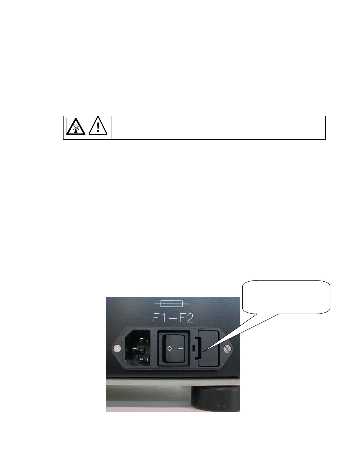
Fusing:
following location:
• F1 and F2 are located on the bottom rear panel and are a part of the power entry module,
The Universal Hood II has two user serviceable fuses. These are located at the
please see picture below for details:
WARNING: The operator should wear appropriate safety glasses or a
protective mask and gloves in addition to using the UV Safety Shield
provided with this instrument.
.
The Universal Hood II has a power supply that automatically
Fuse F1 and F2 are located in
this drawer. Use a screwdrive
and pull the drawer out to see
the fuses
Main power entry module
Page 8 of 42
Page 9

Section 3 Product Description
3.1 CCD Camera and Lenses
A CCD Camera is placed on top of the Universal Hood II for capturing images. The Camera
comes with a Motorized Zoom Lens (MZL) that allows a remote adjustment of the lens control
functions viz. zoom, focus and iris.
For ChemiDoc
extreme light collection efficiency for low light applications like chemiluminescence.
Lens f 0.95, 25 mm, Wide Angle 1708072
Lens f 0.95, 17 mm, Wide Angle 1708073
3.2 Darkroom Enclosure, Emission Filters, and Illumination Sources
The Universal Hood II is designed to capture fluorescence and chemiluminescence images
without using a photographic darkroom. The enclosure has built-in white light epi-illumination
and a UV transillumination. An optional White Light Transilluminator (170-7950) or a White
Light Conversion Screen (170-8001) may also be used with the system.
For easy sample loading, the UV transilluminator is located in the drawer of the Universal
Hood II and can accessed from the front of the enclosure. For your convenience, the lights in
the darkroom enclosure turn off automatically after about 15 minutes. This time period can be
extended indefinitely by pressing the HOLD button.
The Universal Hood II has a three position Filter Slider that offers the flexibility of using two
different emission filters for fluorescence applications as well as the ability to image
chemiluminescence samples (no filter).
Bio-Rad Laboratories offers a selection of filters and illumination sources.
Standard Filter: Comes with each system.
548-630nm Amber Filter (Ethidium Bromide) 170-8081
Optional Filters: Can be purchased for Optimal performance.
520DF30 nm Optional Filter for SYBR Green/ SYBRGold/ GFP/
560DF50 nm Optional Filter for CY3/Rhodamine/Sypro Orange 170-8075
630BP30 nm Optional Filter for SYPRO Ruby/Texas Red 170-8076
480BP70 nm Optional Filter for Hoechst/Coumarin 170-8077
Optional Illumination Sources:
White Light Transilluminator 170-7950
White Light Conversion Screen 170-8001
302 nm UV lamps 6 ea. (shipped standard with each system) 170-8097
254 nm UV lamps 6 ea 170-8098
365 nm UV lamps 6 ea 170-6887
XRS systems optional lenses with low F-number are available that offer
Fluorescein 170-8074
Page 9 of 42
Page 10

3.3 PCI interface Cards
Gel Doc XR:
The Gel Doc XR system requires a Fire Wire port to communicate with the computer where
the user interface software is installed. In case of computers that do not offer a Fire Wire
(IEEE1394) interface, a PCI Fire Wire card (included with the system) needs to be installed in
the computer to communicate with the Camera.
Note: Read and follow the instructions for installing the PCI card, drivers and Software
in Appendix C and D.
ChemiDoc XRS:
The ChemiDoc XRS system requires a PCI Digitizing card to communicate with the Camera.
This card needs to be installed in all PC and Mac systems with appropriate drivers (included in
the software).
Note: Read and follow the instructions for installing the PCI card, drivers and Software
in Appendix C and D.
3.4 Quantity One Software
Each system ships with 1 full version of Quantity One and unlimited copies of Quantity
One
Basic Mode. The software can be used to annotate and document images, analyze
molecular weights, print, and perform a host of other applications. See the software manual for
detailed instructions on how to install and operate the software.
Note: Read and follow the instructions in Appendix C and D prior to installing Quantity
One software.
3.5 Printer (Optional)
For your convenience, Bio-Rad offers an optional USB printer for use with the Gel Doc XR
and ChemiDoc
XRS:
Sony UPD895 (recommended for both the systems) 170-8066
3.6 Packaging
The Gel Doc XR, or ChemiDoc XRS systems consist of multiple components. Each of
them may be in a separate box or in one box with a label describing the catalog numbers and its
contents. Please make sure that all the system components are in your shipment. Please unpack
each component carefully and verify that you have the correct one. Each system includes the
following:
Page 10 of 42
Page 11

Part # Descriptions
170-8170/170-8171 Gel Doc XR System PC/Mac
170-8062 Universal Hood II W/TLUM 100/240 Vac
170-8172 Gel Doc
170-8173 Gel Doc
170-8080 Kit Accessory, Universal Hood II
170-7964/7963 Cable, Serial, MZL, PC/Mac
170-9600 Quantity One
170-8009 Adapter, USB to Serial (Mac System only)
XR Camera and Cable w/MZL
XR Fire Wire card (PC System only)
Software PC/Mac
Part # Descriptions
170-8070/170-8071 ChemiDoc
170-8062 Universal Hood II W/TLUM 100/240 Vac
170-8088 ChemiDoc
PCI card and Camera Controller Cable)
170-8080 Kit Accessory, Universal Hood II
170-8008 Fluorescent Reference Plate
170-7964/7963 Cable, Serial, MZL, PC/Mac
170-9600 Quantity One
170-8009 Adapter, USB to Serial (Mac System only)
XRS System PC/Mac
XRS Camera W/MZL (including
Software PC/Mac
Page 11 of 42
Page 12
Section 4 Getting Started
4.1 Selecting a Location
The Gel Doc XR and ChemiDoc XRS systems can be placed on any bench top. The best
position is near the computer where Quantity One
space to easily access the power switch on the Universal Hood II, which is located at the rear
bottom left side of the enclosure
4.2 Assembling the System
4.2.1 Assembling the Universal Hood II
Important: It is recommended that the Universal Hood II be carried by at
Be sure that the door and the drawer are completely closed.
Wichtig:
Geraeteboden halten.
a) Open the box and review the unpacking instructions.
b) Carefully remove all of the components of your system.
c) Remove the top foam and the plastic wrapping from the Universal Hood II.
d) Carefully pull the enclosure out of the bottom foam and place it in a suitable location.
Note: Please do not connect the power cable to a power source until all connections are
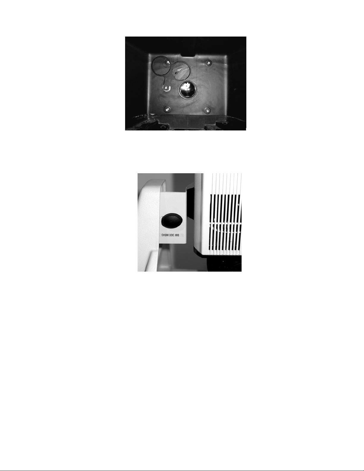
made. The power source has to be grounded and protected by a circuit breaker.
e) Locate the Amber Filter in the Accessory Kit and thread it onto one of the two 62 mm
rings of the Filter Slider (inside of the hood). The Filter Slider facilitates the selection
between two filters and an open position for chemiluminescence.
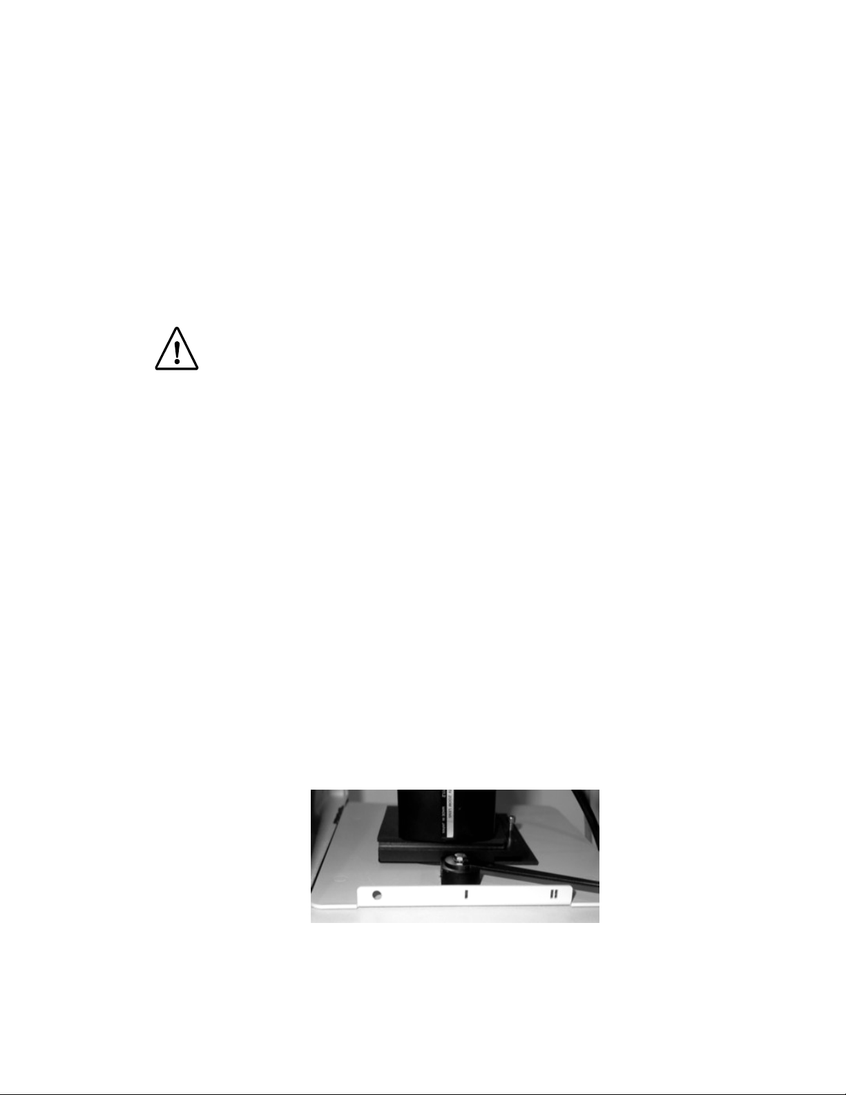
f) The three selectable positions are indicated by three symbols
II (filter 2)
Filter for future use. See pictures below.
least two people holding the instrument from the bottom side.
Es wird empfohlen , dass mindestens zwei Personen den
Hood transportieren und dabei das Geraet am
on the right side of the Camera support. Note the position of the Amber
will be operating. Remember to leave
O (no filter), I (filter 1) or
Three positions sliding filter
Page 12 of 42
Page 13
4.2.2 Assembling the CCD Camera
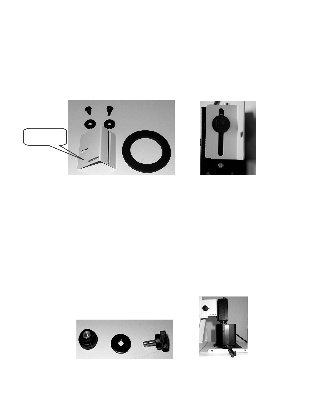
Gel Doc XR
Bracket
Gel Doc XR
a) Place the Camera on the bench so that the two tripod mount holes are facing you.
b) Using one of the two knurled screws and washers attach the Gel Doc
bracket to the
Camera as shown in the picture below. Use the tripod mounting hole that is closest to the
top of the Camera. Do not tighten the screws yet.
c) The black adapter ring provided (3 millimeters thickness) has a soft and a hard side to it.
d) Position this adapter plate on top of the Universal Hood II such that the soft side of the
ring is facing up and the ring is concentric with the round opening on the universal hood.
Gel Doc XR bracket, washers, screws and adapter Gel Doc XR Camera and bracket
e) Place the Camera over the Universal Hood II by inserting the lens into the adapter ring.
f) Make sure that the front of the lens is in direct contact with the black adapter ring.
g) Verify that the lens is centered in the opening on top of the enclosure. To do this you may
need to move the entire body of the Camera and the ring so that the lens is also in the
center of the adapter ring.
WARNING: Failing to center the lens in the adapter ring and the hood can cause the
focusing ring located on the front side of the lens to mechanically rub or bind.
h) Secure the Gel Doc XR bracket (attached to the Camera) to the bracket of the Universal
Hood II using the screw and knurled knob (see pictures below)
i) Tighten the two screws of the Gel Doc
XR Camera bracket. Check that the lens is well
positioned on the black adapter ring for a complete light seal.
j) A completely assembled Camera will look like the picture shown below.
Screw, washer and knurled knob Gel Doc XR Camera assembled
Page 13 of 42
Page 14

Upon completion of the Camera installation, refer
to Section 4.2.3
and
Appendix A
for a
complete description of the cable connections.
ChemiDoc XRS
a) Place the Camera on the bench so that the locking hole of the tripod mount is facing you.
b) Fix the ChemiDoc
XRS bracket to the Camera, do not tighten the screw.
c) Place the black adapter ring (6 millimeters thickness) on the top of the hood with its soft
side facing up.
Tripod Mount
ChemiDoc
XRS Camera with bracket
Black adapter ring for ChemiDoc XRS Camera and its positioning on the top of the Hood
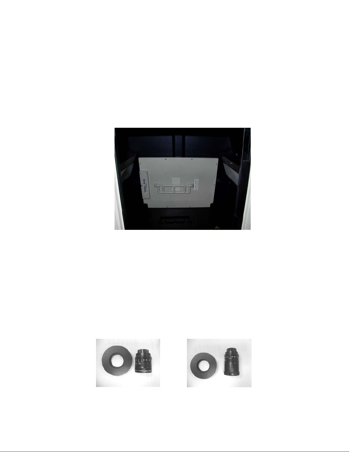
d) Position the ChemiDoc XRS Camera over the opening on the top of the enclosure by
inserting the lens through the adapter ring. Make sure that the lens is in close contact
with the black adapter ring. Adjust the Camera position such the lens is well centered in
the opening of the hood (see below).
Page 14 of 42
Page 15
Center the lens in the opening of the hood as viewed from
inside of the hood
e) Fix the Camera bracket to the bracket on the Universal Hood II using the screw, washer
and knurled knob.
f) Lower the Camera so that the lens fit properly on the gasket of the black adapter ring
then tighten the black screw on the tripod mount
Upon completion of the Camera installation, refer
to Section 4.2.3
and
Appendix B
complete description of the cable connections.
4.2.3 Connecting the cabling harnesses
The cable connections are different if you are installing a Gel Doc XR or a ChemiDoc
XRS Camera. Please refer to the instructions included in
Doc
XR/ ChemiDoc XRS cable wiring.
Appendix A, B
The controls for the Motorized Zoom Lens can be operated from the membrane touch pad of
the Universal Hood II or from the PC using the buttons that appear in the window when the
option Gel Doc
XR or ChemiDoc XRS is selected in the File Menu of the Quantity One
program. To use this option it is necessary to connect the Universal Hood II serial port
(DB25) (on the back left side) to the COM1 of the computer. The PC/Mac cable is included.
Note: In the case when a Mac has a USB port instead of the serial port, use the USB to
serial adapter (included with Mac systems) to control the lens via software.
respectively for Gel
for a
Page 15 of 42
Page 16
4.2.4 Installing the White Light Transilluminator (Optional)
To install the White Light Transilluminator, open the door to the enclosure and pull the
drawer completely toward you. Locate the power cable positioned on the left side (inside of
the enclosure) behind the slide of the drawer. Remove the black rubber that covers the
banana plug and insert it into the White Light Transilluminator outlet. Make sure that the
main power switch on the transilluminator is in the ON position. The transilluminator will
not illuminate. Power to the White Light Transilluminator is controlled from the membrane
touch pad. To use the White Light Transilluminator, place it horizontally on the UV
Transilluminator and press the
TransWhite
White Light Transilluminator is not in use, store it in the two plastic holders located at the
rear of the enclosure.
button on the membrane touch pad. When the
Storage of the White Light Transilluminator
4.2.5 Installing the Optional 17 mm or 25 mm Wide-Angle Lenses (ChemiDoc
XRS only):
This installation guide covers installation of the optional lenses for the ChemiDoc XRS
system. The following catalog numbers are covered under this category:
i. Lens f 0.95, 25 mm, Wide Angle
ii. Lens f 0.95, 17 mm, Wide Angle
The lens kit includes a lens and the Light Seal adapter ring. See pictures below:
25 mm Wide Angle Lens with
Light Seal Adapter ring
17 mm Wide Angle Lens with
Light Seal Adapter ring
Page 16 of 42
Page 17
Setting Up the Lens:
1. Turn off the power to the enclosure and Camera
2. Disconnect the Camera and lens cables
3. Remove the ChemiDoc
XRS Camera from the bracket.
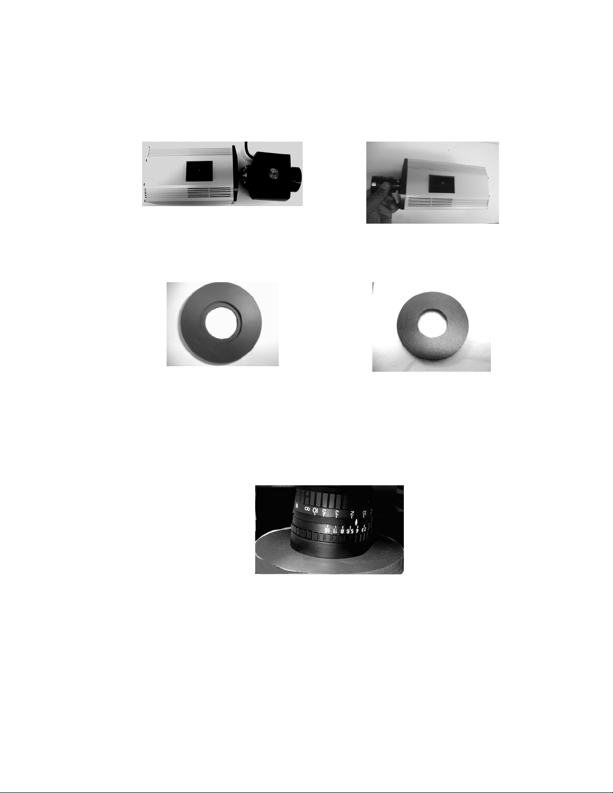
4. Remove the existing Motorized Zoom Lens from the Camera by turning the lens
counterclockwise. Attach the 25 mm or 17 mm lens to the Camera as shown below:
Remove existing Motorized Zoom Lens Install the Wide Angle Lens
5. The Wide Angle Lenses comes with a Light Seal that is donut shaped. One side is soft and
has a groove around the inner opening. The other is hard. See picture below
Light Seal soft side (Note groove) Light Seal hard side
6. Position the Light Seal on the top of the hood. Make sure that the “hard side” is against
the top of the enclosure. Secure the Camera (with wide-angle lens attached) to the Camera
bracket with the black washer and the thumbscrew. Before tightening the screw make sure
that the wide-angle lens is positioned in the round slot in the Light Seal (soft side up).
Carefully push the Camera down so that the lens goes into the slot all the way and comes
to a stop. See pictures below:
Make sure that the lens is seated properly in
round slot in the soft side of the Light Seal
7. Adjust the position of the bracket so that the Light Seal and lens are well centered in the
round opening in the Universal Hood II and tighten the screws to secure the Camera tightly
to the hood.
8. The Wide Angle lenses have an Iris and Focus ring that allows users to adjust for optimum
light collection and focal plane. See image on the next page.
Page 17 of 42
Page 18
Focusing Ring
9. For imaging of chemiluminescent samples, make sure that the Iris is opened all the way.
4.3 Description of System Function and System Initialization
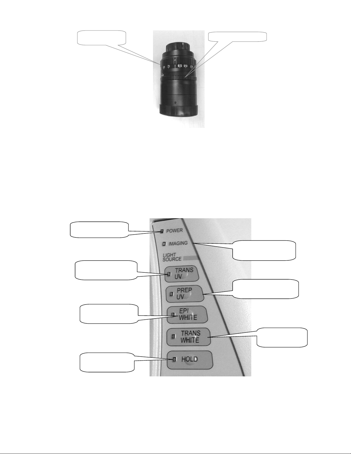
4.3.1 Control panel
The front membrane touch pad control panel of the Universal Hood II allows full control of
the Motorized Zoom Lens, UV transillumination, White Epi illumination and White Light
transillumination. Please read the following section to become familiar with each function.
Power Indicator
Imaging Indicator LED
Trans UV LED and
button
Prep UV LED and
button
Epi-White LED and
button
Hold LED and
button
Membrane Touch Pad
The
light tells you whether the system is turned on or not. The power on/off switch is
Power
located at the rear bottom left side of the enclosure.
Page 18 of 42
Trans White LED
and button
Page 19

The
Imaging
not present using the Gel Doc
led blinks when you are acquiring an image with the Camera (this function is
XR or ChemiDoc XRS Cameras) indicating integration by
the Camera. It also blinks if the computer is turned off.
Light Sources
The
Epi-White
button controls the Epi White illumination. Press the button to turn ON EpiWhite; press the button again to turn it OFF. Epi illumination will automatically turn off after
15 minutes, unless the
activated
The
Epi-White
White Light Trans
is automatically turned off.
(optional). It will automatically turn off after 15 minutes, unless the
The
UV Trans
button controls the UV Transilluminator with full intensity. The
transilluminator will automatically turn off after 15 minutes unless the
button is activated. When the UV transilluminator switch is
Hold
button controls the White Light Transilluminator when installed
button is activated.
Hold
button is
Hold
activated. For safety purposes, this switch is subject to the following automatic controls:
It is automatically turned off when the front door is open.
•
It is automatically turned off when the drawer is open.
•
If the door or drawer is opened while the transilluminator is ON, the blinking LED will warn
you that the transilluminator has been turned OFF. After the door or the drawer is closed, you
have to press the UV Trans switch again to turn it ON.
Important: For the purposes of band cut applications, it is possible to
turn ON the UV light with the drawer fully open. You must wear all possible UV
protections, especially for your eyes, when the transilluminator switch is turned ON
with the drawer fully open. The UV shield has to be used but glass or mask and gloves
are recommended to block the UV radiations. This option is not applicable to the door.
Wichtig: Wer die Absicht hat, Banden aus dem Gel zu schneiden, kann bei
eingeschaltetem UV-Licht die untere Schublade oeffnen. Sie muessen Schutzkleidung
und die notwendigen UV-Schutzmassnahmen tragen, besonders Augenschutz, wenn der
transilluminator bei offener Schublade eingeschaltet ist. Das Plexiglasschutzschild muss
benutzt werden, ebenso Schutzbrille oder Schutzmaske und Einmalhandschuhe, um sich
vor der UV-Strahlung zu schuetzen. Diese Moeglichkeit ist von der Geraetetuer aus
nicht anwendbar.
The
UV Prep
switch is used to decrease the light output of the UV Transilluminator. The UV
Preparative function is a lower intensity light designed to minimize the effects of UV
exposure on DNA. The Preparative mode is recommended for applications that require longer
UV exposure times. In order to activate the UV Prep switch, the UV Trans button must be
on.
The
key disables the automatic shut-off of the UV and White light transilluminators and
Hold
the Epi-illumination; the lights will remain active until the hold status is cancelled. When the
key is pressed, the orange LED lights, indicating that the
Hold
function is active.
Hold
Page 19 of 42
Page 20

If opening the door or drawer (activating the UV interlock, which turns off the UV), you will
need to turn off the
button before pressing any other switch.
Hold
The control panel has a second section that includes the buttons to run all the MZL functions
(see the Lens Control Section below).
Camera Lens and Filters
The MZL functions are operated from the membrane touch pad or through the acquisition
window in the software. To control the lens through the Quantity One
acquisition window,
it is necessary to connect the Universal Hood II with a null modem cable (serial cable) from
the COM1 port on your computer to the serial port of the hood itself. A serial cable is
supplied with each instrument. If the only port present is the USB port then it is necessary to
use a USB To Serial converter (Part # 170-8009) for PC and for Mac (all Mac systems ship
with a converter).
Lens Control
The membrane pad has a
Fast
and a
button to obtain rapid or fine adjustments of the
Slow
lens. An image can be optimized with the following lens adjustments:
Aperture
is adjusted using the “
aperture opening allows the CCD sensor to take in more or less light. The
buttons: One button,
Close (-),
coming into the sensor, thereby making the image darker. The other button,
” buttons on the membrane touch pad. The size of the
Iris
has two
Iris
reduces the size of the aperture decreasing the amount of light
Open (+)
, opens
the aperture increasing the amount of light coming into the sensor, resulting in a brighter
image.
is adjusted using the “
Focus
the
Far (-)
button changes the focal point of the lens and allows the user to focus on the
” buttons on the keypad. Pushing the
Focus
Near (+)
button or
sample.
is adjusted using the “
Zoom
of the image on the screen. Pushing the
Tele (+)
button zooms in (close up).
” buttons on the keypad. It allows you to change the size
Zoom
Wide (-)
button zooms out (far field). Pushing the
Membrane touch pad – Lens Control Section
Page 20 of 42
Page 21

Filters: A +1 Diopter
the lens assembly. An
is factory installed on the lens. This Diopter should always remain on
Amber Filter
is included in the Accessory Kit. Place the Amber filter
in position 1 or 2 of the Filter Slider (See 4.2.1). The Amber filter should be used for
fluorescence (UV) and colorimetric (White light) applications.
4.3.2 System Initialization
Before starting the initial test please make sure that:
1. The software and the digitizing board are installed properly (See
2. The cabling harness is connected properly. (See
Appendix A or B
Please follow the procedure in the table to ensure that the Universal Hood II is functioning
properly.
STEP 1: Initial test for the Universal Hood II:
Procedure
Make sure the door and drawer are closed and the computer is switched on.
Turn on the system. Power LED turns on after short blinking.
Wait for 30 minutes for Camera to
warm up
Nothing will change except the Camera will warm
up.
Press the Epi-White key. Epi-White LED turns on.
Open the door. Epi-lights are on, Trans UV LED blinks.
Press the Epi-White key again.
Close the door.
Epi-lights and LED are turned off.
Trans UV LED turns off.
Press the Trans UV key. Trans UV LED turns on.
Open the door. Trans UV LED blinks.
Close the door. Trans UV LED turns off.
Press the Trans UV key. Trans UV LED turns on.
Open the drawer. Trans UV LED blinks.
Close the drawer. Trans UV LED turns off.
Press the Trans UV key. Trans UV LED turns on.
Press the Prep UV key Prep UV LED turns on.
Press the Hold key. Hold LED turns on.
Open the drawer. Trans UV LED blinks, Prep UV LED and
Hold LED turns off.
Close the drawer. Trans UV LED turns off.
Note: The Light Source buttons on the control panel are disabled when the Imaging
LED blinks (indicating that the computer is switched Off).
Appendix C and D
)
Control Panel
).
Page 21 of 42
Page 22

STEP 2: Initialization of the Camera and lens assembly Procedure (for Gel Doc XR/
ChemiDoc XRS systems):
1. Press the Epi-Illumination button.
2. Open the door and determine if lights are on.
3. Place the focusing target on the UV transilluminator.
4. Double click on Quantity One
“Gel Doc
XR” or “ChemiDoc XRS”.
software icon on the desktop. From “File Menu” select
NOTE: Dark Reference comes up on first use for both Gel Doc XR and ChemiDoc
XRS
systems. Please refer to next step for details about “Reference Dark” image
acquisition.
5. Select Live/Focus.
6. An image of the target will appear on the computer screen. Using the lens control buttons
on the membrane touch pad or the control panel that appears in the software, find the best
Iris, Focus, and Zoom conditions.
Note: Working with a widely open Iris and changing the Zoom may require you to
adjust the Focus.
STEP 3: Dark Reference Acquisition:
Note: Please note that the steps described below must be performed in either of the
following scenarios:
a. When installing the system with a new computer or Camera
b. When software is first installed or reinstalled for any reason
Page 22 of 42
Page 23

1. Make sure that all lights in the Universal Hood II are off.
2. Make sure that the Lens Cap is on the lens.
This is critical!
3. Power ON the Camera and the Universal Hood II.
4. Wait for 30 minutes for the system to warm up and stabilize
5. Double click on Quantity One
Gel Doc
XR OR ChemiDoc XRS.
software icon on the desktop. From “File Menu” select
TDS Quantity One Window
Select Gel Doc XR OR ChemiDoc XRS from
File Menu
5. The following window will open with a notification that the system will be acquiring Dark
Reference images.
Page 23 of 42
Page 24

Note: No lights should be turned ON. Please allow approximately 30 seconds for the
Gel Doc XR and 30 minutes for the acquisition of the Dark Reference files
ChemiDoc XRS systems.
1. After the “Dark Reference” acquisition is over the system will be ready to operate.
2. Turn ON the Epi-White lights using the Epi-White touch pad button.
3. Place the focusing target on the transilluminator platen.
4. Click on Live/Focus.
5. An image of the target will be seen on the imaging screen.
6. Using the lens control buttons on the membrane touch pad or the control panel that appears
in the Quantity One
acquisition window, adjust the Iris, Focus, and Zoom.
7. Follow the procedure below to align the Camera with respect to the center of the platen.
Note: For additional details on Dark Reference Acquisition refer to the Quantity One
Software Manual.
4.3.3 Aligning the Camera assembly:
Centering the CCD Camera on the opening in the top of the Universal Hood II should provide
good alignment of the Camera with the center of the UV transilluminator. To verify, please
follow the instructions below:
1. Place the focusing target in the center of the transilluminator.
2. Switch on the Epi-White light.
3. Open the acquisition window in Quantity One
image of the target is seen on the monitor.
4. Focus on the target.
5. Click on “Show Alignment Grid” button located near Live/Focus button. A red cross hair
will appear in the middle of the imaging area.
6. Loosen the bracket screw and move it slightly until the black square of the target matches
with the red X-mark in the image. Tighten the screw to secure the Camera in place.
7. Select “Fast” on the hood. Press “Focus” button to confirm that the lens is responding. If
not, adjust the position of the lens so that the opening on the hood offers no
resistance/binding to the focus ring on the lens. This may not allow exact center of the
Target to the image.
8. Use the zoom button on the control panel to zoom in and out on the image.
9. When the Camera assembly and target are correctly aligned, the center of the target will
move a few millimeters in the center of the image throughout the zoom range.
. Select Live/Focus mode so that a live
Page 24 of 42
Page 25

Section 5 Operation of the Universal Hood II
5.1 Operating the unit
The Gel Doc XR and ChemiDoc XRS Systems are easy-to-use instruments. In the
Quantity One
your image position, size, focus, and intensity using the lens controls. After the image is
optimized, capture the image. A typical procedure is described below.
5.1.1 Switch on the Universal Hood II
1. Turn on the Universal Hood II main switch (on the rear bottom left side of the enclosure).
2. Turn on the computer and start the software.
3. Select the acquisition mode from the File menu.
NOTE: Turn the power on for Cameras if not already done so.
5.1.2 Position your gel
1. Open the door of the Universal Hood II.
2. Press the Epi-Illumination button to turn on the Epi White lights.
3. Center your gel on the transilluminator platen and close the door.
4. Adjust the lens Iris, Zoom, and Focus while looking at the computer screen.
5. Open the door and re-position the gel if necessary.
6. If using the White Light Conversion screen or the White Light Transilluminator, focusing
is easily achieved if the Iris is slightly closed.
5.1.3 Acquire an image
1. Press the appropriate light source for your sample
2. Select an integration time (see software manual for details).
3. When a satisfactory image is seen click
5.1.4 Acquiring an image with Flat Fielding:
Note: This applies to ChemiDoc XRS systems only where Flat Fielding is made
available for acquiring images with UV or White Light Transillumination.
1. Center your sample on the platen.
2. Turn ON the UV or White Light Transilluminator.
3. Adjust zoom, focus and iris to get the best possible image in Live/Focus mode.
4. Make sure that the box labeled “Flat Fielding” is checked to enable Flat Fielding.
5. Select Auto Expose or Manual Expose.
6. Following the exposure, a window will open asking if you would like to use a saved
reference image for Flat Fielding.
7. Select NO unless you have recently acquired a Flat Field reference image and are still
using the same illumination and lens settings.
8. Select YES if you are using the same lens and illumination settings that were used to
previously generate a Flat Field reference image file. See image on the following page.
acquisition window on your computer, select Live/Focus mode and adjust
Freeze
.
Page 25 of 42
Page 26
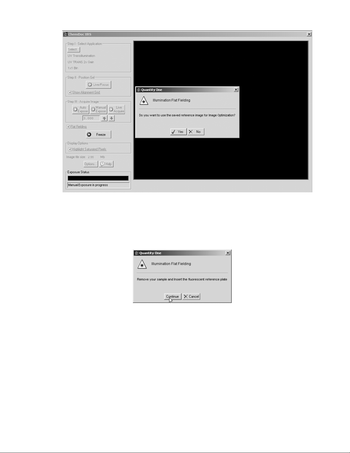
9. Next you will be prompted to remove your sample from the transilluminator and place
the Fluorescent Reference Plate on the platen for UV illuminated images.
Light Illumination the White Light Transilluminator or the UV conversion screen is
used to collect the reference Flat Fielding image. In either case you must remove the
sample from the platen.
For White
Page 26 of 42
Page 27
10. Remove the sample from the transilluminator. Remove any liquid or residue remaining
from the sample platen. Place the Fluorescent Reference Plate on the platen. Make sure
that the plate covers the entire glass surface. Close the door and then click on “Continue”
in the window shown above.
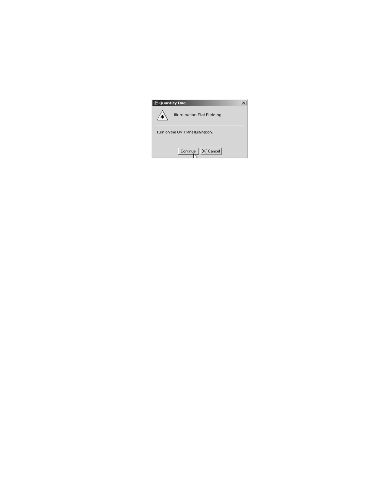
11. The next prompt will direct you to turn ON the UV transilluminator. Press the UV
transilluminator or White transilluminator button on the hood, as the case may be, and
click on “Continue”.
Page 27 of 42
Page 28

Note: When using the White Light, you must turn ON the UV Transilluminator after
removing the sample.
12. The system will automatically acquire a reference image and a flat-fielded corrected image
of the sample will be generated for you to save and analyze.
13. For additional details on Flat Fielding please refer to the Quantity One
You may also click on the Quantity One
HELP button for a detailed description.
Software Manual.
5.2 Cutting gels
1. Open the drawer until it is fully extended and the UV Trans LED stops blinking.
2. Place the clear acrylic UV protection screen in the horizontal slot in the inside of the
drawer facing the transilluminator.
!! CAUTION!! !! VORSICHT !!
WARNING: EXPOSURE TO UV RADIATION IS HAZARDOUS TO HEALTH.
PLEASE WEAR PROPER UV PROTECTIVE CLOTHING AND FACE AND EYE
SHIELDS WHEN CUTTING GELS. THE UV SHIELD PROVIDED WITH THE
SYSTEM IS NOT ADEQUATE PROTECTION AGAINST UV GENERATED BY
THIS SYSTEM.
3. Press the UV Trans button to turn on the UV illumination.
4. Cut the gel.
5. Press the UV Trans button and the UV transilluminator will turn off. Remove the acrylic
UV protection shield before closing the drawer.
Page 28 of 42
Page 29

Section 6 Trouble Shooting
Problem
Possible Cause
Solution
Image is not visible on the
monitor
Image is not bright enough.
Impossible to image whole
sample area.
Printout does not look the
same as the image on the
monitor.
Light leakage into the
darkroom.
Hot (very bright) pixels are
seen in the image
(ChemiDoc
Hot (very bright) pixels are
seen in the image (Gel Doc
XR only)
ChemiDoc XRS Camera
will not respond
ChemiDoc XRS image will
not Auto expose
Unable to focus on the
sample using White Light
transilluminator or
conversion screen
XRS only)
Aperture is closed.
•
Incorrect monitor
•
settings
Wrong cable
•
connections.
Wrong aperture setting
•
Insufficient exposure
•
time
Lens is zoomed-in too
•
close.
Monitor settings are
•
wrong.
Thermal printer settings
•
are wrong
The lens body is not
•
properly centered and
against the light seal
gasket on the hood
• Τ
MZL not closed with
the screw.
“Reference” is not
•
selected for “Dark
Subtraction” in the
OPTIONS window
Corrupted “Reference
•
Dark” image
Power may be off
•
Controller cable may
•
not be seated properly
Software Driver for the
•
Camera is missing
Camera may be
•
defective
The sample is too
•
bright and saturates the
image at the minimum
possible exposure
Aperture is open too
•
wide causing a shallow
depth of field
he rear hole on the
Open the aperture.
•
See your computer manual
•
See Appendix A or B for
•
correct cabling.
Open the aperture
•
Select longer exposure time
•
Zoom-out the lens.
•
Read the manual for the
•
printer
to ensure proper settings
Loosen the bracket and move
•
the Camera around to properly
seal the opening on the hood
or adapter plate as the case
may be.
Close the hole with the black
•
plastic screw.
Select “Reference” by clicking
•
on the appropriate box in the
OPTIONS window.
Click on “OPTIONS” button
•
and then click on “RESET
REFERENCE DARK”
Turn ON the power to the
•
Camera
Make sure that Camera
•
controller cable is connected
properly
Install Quantity One again if
•
the driver is not present
Replace Camera
•
Close the IRIS using the IRIS
•
control until Auto expose is
possible.
Close the Iris slightly and then
•
focus again. Keep repeating
until good focus is achieved
Page 29 of 42
Page 30

Section 7 Accessories and Replacement Parts
Accessories and Replacement Parts
Part
number
170-8001 UV/White Light conversion Screen,
170-7950 White Light transilluminator upgrade for Universal Hood II
170-8066 Printer, Digital, Sony UPD905, 100-240 Volts
170-8067 Paper, High Gloss, Sony UPD895, 5 Rolls
170-8074 Filter, 520DR30
170-8075 Filter, 560DF50
170-8076 Filter, 630BP30
170-8077 Filter, 440BP70
170-8081 Kit, Filter, Amber, 62 mm
170-8072 Lens,f/0.95, 25mm, wide angle lens (ChemiDoc XRS only)
170-8073 Lens,f/0.95, 17mm, wide angle lens (ChemiDoc XRS only)
170-8068 Shield, UV, Universal Hood II
170-3759 Bio-Rad fluorescent Ruler
170-3760 Gel Cutter Ruler
170-7813 Sample Holders for gels
170-8008 Fluorescent Reference Plate (ChemiDoc XRS only)
170-8009 Converter, USB to Serial (Includes USB Cable)
931-0071 Cable, USB, Type A to B, 10’ long
100-1381 Lamp, Epi-illumination, 11 Watt
100-2827 Lamp, Epi-illumination, 5 Watt
100-1361 Lamp, UV B (302 nm – 1 each)
170-8097 Kit, 6 lamp, 302 nm,
170-8098 Kit, 6 lamp, 254 nm,
170-6887 Kit, 6 lamp, 365 nm,
170-8080 Kit, Accessory, ChemiDoc
100-2651
170-8173
100-2649
100-2799 Cable, Extension, MZL Univ Hd II
170-7963 Cable, Serial, Mac
170-7964 Cable, Serial, PC
100-0578 Cable, Fire Wire, 10’
100-0579 Power Supply Camera Gel Doc XR
170-8088 ChemiDoc
100-2648
170-8096 Lens, Motorized, 8-85 mm, f 1.2 (Gel Doc XR)
931-0198
100-2781
100-2782
921-0929
100-2783 Screw, knurled knob and washer
Description
XRS
XRS
XRS
XR
XRS
Card, PCI Digitizing, ChemiDoc
Card, Fire Wire, PCI, Gel Doc
Cable, Controller, ChemiDoc
XRS Camera w/MZL
Power Supply, Camera, ChemiDoc
Lens, Motorized, 12-75mm, f 1.2 (ChemiDoc
Black Adapter Ring for Gel Doc
Black Adapter Ring for ChemiDoc
Light Seal, Optional Lenses, ChemiDoc
XR (3 millimeters thickness)
XRS (6 millimeters thickness)
XRS
XRS)
Page 30 of 42
Page 31

100-2784 UV transilluminator Lid (Includes filter glass)
100-2785 Universal Hood II Right Shield Epi-illumination (Lid complete)
100-1948 Universal Hood II Opal Filter Epi-illumination (w/o metal frame)
100-2786 Universal Hood II Left Shield Epi-illumination (Lid complete)
100-2787 Universal Hood II Screw Feet (4)
100-1951 Fuse T 2 A – 250 V (10 each)
100-1952 Fuse T 4 A – 250 V (10 each)
100-1370 UV TR Starter (3 each)
170-9600
Quantity One
Software PC/Mac
Page 31 of 42
Page 32

Section 8 Maintenance and Part Replacement
This section covers the replacement of parts in the Universal Hood II.
8.1 Epi-illumination lamp replacement
The lamps are located behind the two panels on each side (left and right) of the internal side of
the hood.
• Turn system power off.
Remove the power cord.
•
Open the enclosure door.
•
• Locate the Epi lamp housing.
• Locate the socket head screw that hold each lamp housing to the internal side of the hood.
• Remove this screw.
The cover screen with a plastic piece will come loose. Pull on the cover to remove it from
•
the box and the lamp will become visible.
• To remove the lamp, hold it from the receptacle and then pull it from the plastic Holder.
• Insert the new lamp (5 or 11 W) into the lamp holder and then push it into the receptacle.
• Reassemble the cover.
8.2 Fuse replacement
Always unplug the instrument before changing or checking the fuses.
Power Cable plug-in
Epi-White Light 5 W assembly (left side)
Fuse holder
ON/OFF Main Switch
Power Entry Module
Page 32 of 42
Page 33

This unit is protected by 2 fuses 5X20 mm 2A Slow Blow. The fuses are located in the rear left
side in a fuse holder. See above picture.
1. Unplug the main power cable from the power entry module outlet.
2. Using a screwdriver lever on the fuse holder to extract it.
3. Remove the blown fuses and replace them with two new ones (P/N 100-1951).
4. Slide the fuse holder into the power entry module until it snaps in place
8.3 UV Transilluminator
UV transilluminator without cover
8.3.1 Lamp replacement
Attention: The UV filter surface should always be kept clean from the chemical agents
used as gel dyes. Please use protective gloves when touching the UV transilluminator
cover.
The lamps must be replaced after every 500 hours of use.
• Turn off the power.
• Disconnect the power cord from the Universal Hood II.
Remove the four screws located on the left/right sides of the drawer.
•
• Remove the cover with the UV filter by sliding it forward.
• Place it down on its backside on a non-abrasive surface.
Caution: Do not put the UV filter directly on the bench.
• Wear gloves when touching the lamps. Remove the lamp by rotating it until it becomes
loose and the pins come to a vertical position;
Remove the lamp. Install the new lamp by rotating so that the pins are horizontal and the
•
lamp is tight.
• Reassemble the cover and retighten the screws on both sides.
Page 33 of 42
Page 34

Lamp replacement Starter replacement
8.3.2 Starter replacement (P/N 100-1370)
Turn off the power.
•
• Disconnect the power cord from the Universal Hood II.
• Remove the four screws located on the left/right sides of the drawer.
• Remove the cover with the UV filter by sliding it forward.
• Place it down on its backside on a non-abrasive surface.
Caution: Do not put the UV filter directly on the bench.
• To remove the starter, rotate it counter-clockwise and pull out.
• To replace the starter insert it into the holder and rotate clockwise.
• Reassemble the cover and retighten the screws on both sides.
Page 34 of 42
Page 35

Appendix A: Gel Doc
Connecting the cabling harnesses
a) Locate the Fire Wire cable. Connect one end of the Fire Wire cable connector to the Fire Wire
connector on the Camera and connect the other end to the Fire Wire connector on the PC/Mac
b) The Camera power supply cable should be plugged into the CCD Camera PWR connector.
c) Connect the serial cable to the connector labeled
this cable to the appropriate port on the PC or Mac USB to Serial Adapter.
d) Connect the MZL cable connector to the connector labeled
universal hood.
The following table describes the connectors and their designations.
Label / Color
6-pin Fire Wire connector Fire Wire Connector of the PC or PCI Card
6-pin Fire Wire connector CCD Camera Fire Wire Connector
Camera Power Supply Cord/Power Supply Camera / PWR Connector
25 Pin D-SUB Serial Cable connector COM1 PORT/Back of Computer
5 pin DIN Cable from Motorized Zoom Lens Hood / LENS connector
XR System Cable Configuration
“SERIAL”
Instrument / Connection
on the hood and the other end of
“LENS”
Power Cable
from Power
on the rear panel of the
Supply
CABLE
MZL
Fire Wire Cable
SERIAL CABLE
To Mains
110-240 VAC
Page 35 of 42
Page 36

Appendix B: ChemiDoc XRS System Cable Configuration
a. Connect the motorized zoom lens cable (which is permanently attached to the lens) to the MZL
Extension Cable and then to 5-pin din connector labeled
hood.
b. Connect the
Camera power cable
to the connector on the Camera labeled
picture below)
LENS
on the
connector panel
POWER
of the
(See
Camera Power Supply Camera Power Cable Power connector on the Camera
c. Connect one end of the
DATA
card is installed in the
and the other end of this cable should be connected to the
PC
Camera Controller cable
per procedure in Step 4.2.3.
to the connector on the Camera labeled
PCI Digitizing Card
Camera Controller Cable and Connector Controller Cable Connector labeled Data
d. Connect the provided
PC/Mac
e. In case of a
included) with a
Mac serial cable
and the other end of the
with a
Mac
USB cable
(170-7963) between the adapter and the Hood.
Serial Cable
25 pin serial connector
, connect the optional (170-7959)
USB
to the
to the
Mac
9-pin D-SUb/8 pin round
and then connect the
on the Hood.
8 pin round connector
serial connector on the
USB to Serial adapter
f. Now proceed with installation of the PCI Digitizing Card and software.
after the
(not
of the
CONNECTOR PANEL FOR ON THE HOOD
Page 36 of 42
Page 37

Appendix C: Installing Software and Drivers
Gel Doc XR and ChemiDoc XRS- PC:
CAUTION: You must install the drivers BEFORE installing the PCI card.
a. Insert the Discovery Series CD into the CD ROM drive of the PC. It will go into AUTO
RUN mode and the following window will open:
a. Depending on which application you are using (Quantity One
or PDQuest), click
“Install” to run the installer.
b. If this is a new installation, follow the installation steps until you get to the “Select
Features” dialog box. If you have already installed the application, click Modify to open
the “Select Features” dialog box.
Page 37 of 42
Page 38

c. Click the Driver feature (ChemiDoc XRS/VersaDoc or Gel Doc XR) and select
“Will be installed on local hard drive.” from the list:
d. Click “Next” to complete the installation.
Note: If the Windows Device Manager detects a conflict, it may be necessary to move
the PCI card to a different slot to avoid conflict with an existing card in the PC.
Page 38 of 42
Page 39

Gel Doc
XR and ChemiDoc XRS- Mac:
a. Insert
b. Double click on the CD icon the following window will open
“The Discovery Series”
will show up on the Apple Desktop as an Icon
software CD into the CD ROM drive of the PC. The CD
Click on the installer for your application and the follow the prompts to to the following
c.
Installation Wizard:
Page 39 of 42
Page 40

From the pull down menu, select “Custom Install”.
d.
c. Select the Driver you want to install. If you have not yet installed the application, be
sure to select that as well.
d. When you have made your selections, click Install to complete the installation.
Also read the Release Notes file for last minute updates for the Software
.
Page 40 of 42
Page 41
Appendix D: PCI Card Installation
Please follow the instructions below to install the Fire Wire Card into your PC/Mac as the case
might be.
Gel Doc XR – PC:
a. Install the PCI Fire Wire card in the PC first
b. Start the computer.
In case of a PC Windows XP or 2000 the operating system will recognize the card and
c.
automatically install the appropriate driver for it.
Gel Doc XR - Mac:
Current Mac systems generally have onboard Fire Wire ports (connectors). The Gel Doc
XR Camera can be plugged directly into any one of these connectors and Bio-Rad Software
interface will be able to communicate with the Camera via this port.
ChemiDoc XRS- PC:
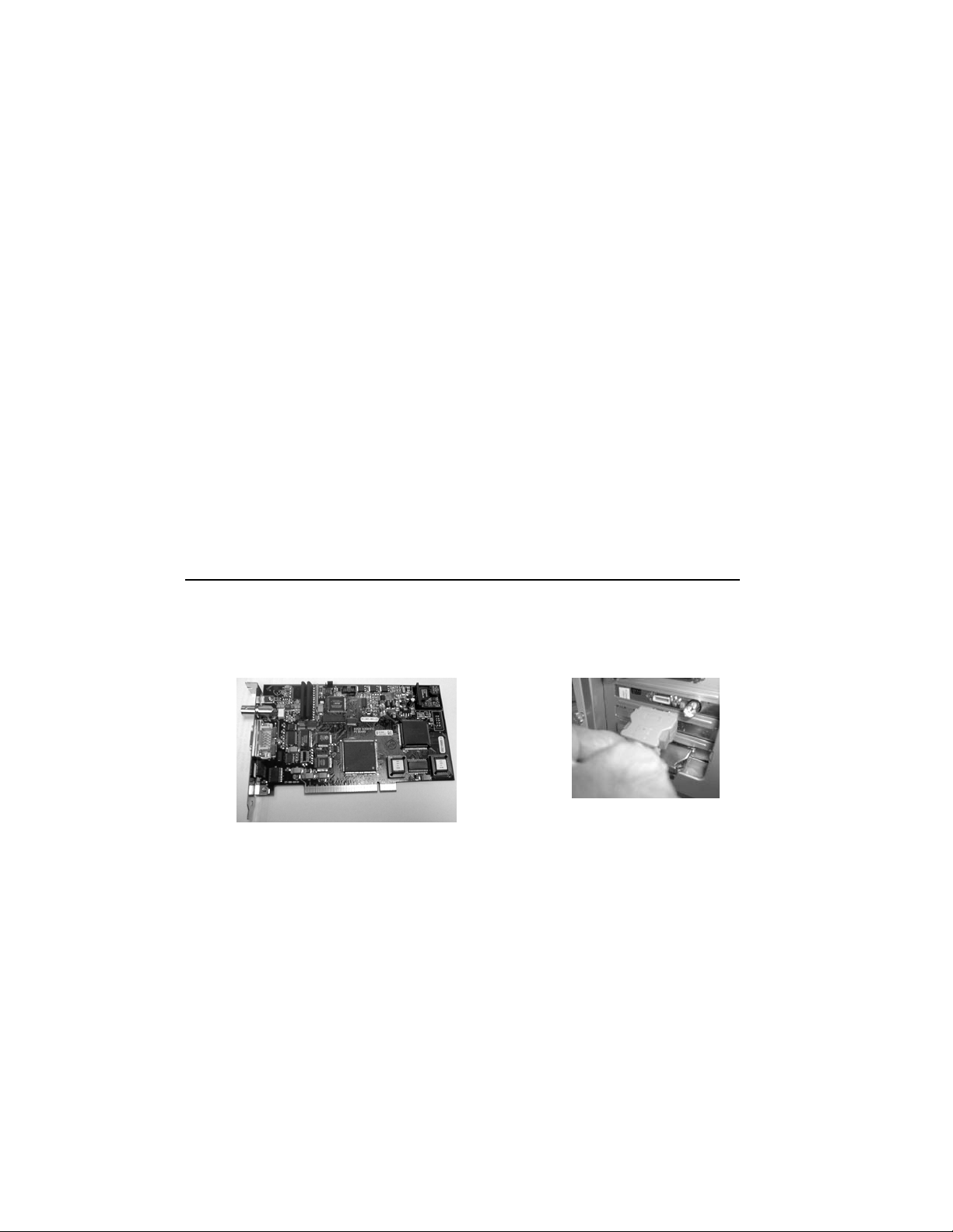
Installing the PCI Digitizing Card
NOTE: When installing the PCI Digitizing Card for the ChemiDoc XRS, please install the
DRIVERS for the Card and the “Quantity One Software” from the software CD first.
Please refer to “Appendix C” for step-by-step instructions for driver installation.
a) Make sure that your computer is turned off. Remove the cover from the computer.
Install the PCI card into one of the PCI slots in the computer (PC/Mac)
b) Close the cover.
PCI Digitizing card for ChemiDoc XRS Connect the ChemiDoc XRS Camera
Controller Cable to the PCI card.
c) In the case of the ChemiDocXRS, connect the Camera Controller Cable to the PCI card
as shown in the picture above. Note that the other end of this cable is connected to the
Camera
d) After all connections are made the system is ready for Initialization as described in
section 4, sub section.4.3.2.
Page 41 of 42
Page 42

Appendix E: Technical Specifications
Model
Application
Chemiluminescence
Fluorescence Yes Yes
Chemifluorescence
Colorimetric/Densitometry Yes Yes
Gel Documentation
Isotopic Imaging No No
Hardware Specifications
Maximum Sample Size
Maximum Image Area 25 x 26 cm 25 x 26 cm
Gel Doc XR ChemiDoc XRS
Yes Yes
28 x 36 cm 28 x 36 cm
No Yes
No No
Excitation Source
Illumination modes
Detector
CCD Resolution (H x V)
Pixel Size (in Microns)
Cooling System
Camera Cooling Temp.
Filter Holder
Emission Filters
Dynamic Range
Pixel Density (gray levels)
Trans UV 302, 254,
365 nm & White,
Epi-White light
3
Trans UV & White,
Epi-White
CCD
1360(H) x 1024 (V) 1300 (H) x 1030 (V)
4.65(H) X 4.65 (V) 6.7 (H) X 6.7 (V)
No Peltier cooled
NA
3 positions
2-Emission Filter
1-Chemi
1 Included (amber),
4 optional
3.0 Orders > 3.0 Orders
12 bit
(4096 gray levels)
Trans UV 302, 254,
365 nm & White,
Epi-White light
3
Trans UV & White,
Epi-White
Super Cooled
CCD
-45°C
3 positions
2-Emission Filter
1-Chemi
1 Included (amber),
4 optional
12 bit
(4096 gray levels)
Dynamic Flat Fielding No Yes
Instrument Size (cm)
Instrument Weight (kg)
Software Specifications
Application Driven Yes Yes
Windows XP
Windows 2000
Mac OS 10
Image File Size (MB) Approx. 2.5 MB Approx. 2.5 MB
Operating Ranges
Operating Voltage
Operating Temperature
Operating Humidity
36(L) x 60(W) x 96(H) 36(L) x 61(W) x 96(H)
32 kg 32 kg
Yes Yes
Yes Yes
Yes Yes
100/115/230 VAC
Nominal
10-28°C (21°C
recommended)
< 70% noncondensing
Page 42 of 42
100/115/230 VAC
Nominal
10-28°C (21°C
recommended)
< 70% noncondensing
 Loading...