

Page 1
1
The BioLogic pH monitor is an in-line electrode and flow cell that provides direct monitoring of pH conditions during
a sample run. It provides real-time monitoring of buffer pH and is designed for flow through pH recordings. The pH
monitor is available as an option to the BioLogic DuoFlow systems and is compatible with the discontinued
BioLogic HR systems. The monitor ships with all Maximizer systems.
The monitor is supplied with a tubing kit that includes installed ¼ -28 fittings. When used with either a DuoFlow or
HR system the pH monitor connects via the Signal Import Module (SIM). When a Maximizer is installed with the
DuoFlow Workstation the monitor connects directly to the system via a BNC port on the Maximizer.
The pH electrode is a sealed Calomel combination electrode consisting of a pH and a reference electrode built into
a single body. The sealed reference design eliminates the need to add electrolyte solutions and minimizes
reference dry out. The pH electrode is fully compatible with buffers (such as Tris) that may not be compatible with
Ag/AgCl containing electrodes. The pH Monitor is designed for use in chromatography applications at flow rates up
to 80 ml/min and a flow cell pressure less than 75 psi.
The flow cell is made of PEEK and has a swept volume of approximately 80ul when the pH electrode is inserted.
These instructions cover the installation, calibration, and maintenance of the pH electrode and flow cell. Be sure to
keep this information with your BioLogic DuoFlow or HR instruction manual for future reference.
Installation Instructions
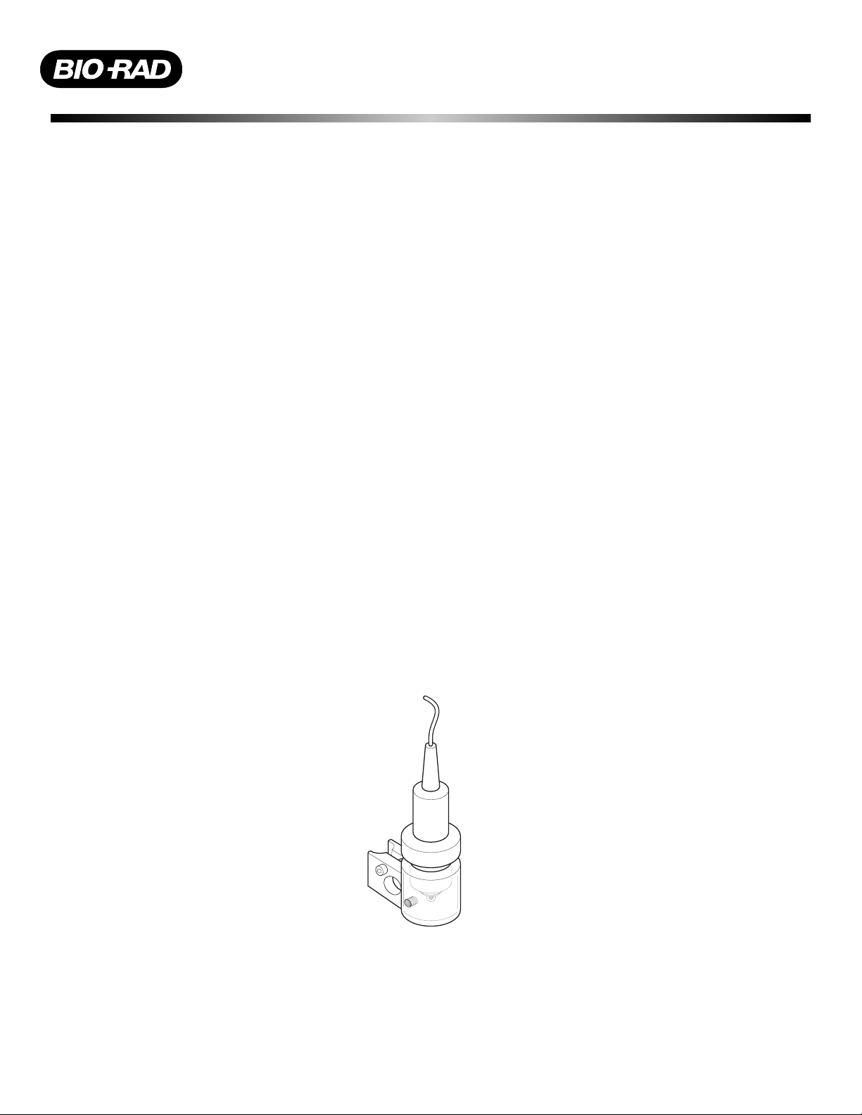
Figure 1. pH Electrode and Flow Cell
The flow cell and pH electrode should be plumbed downstream of any backpressure device or detector. The pH
Monitor has a maximum pressure rating of 75 psi.
DuoFlow pH Monitor
Catalog Number 760-2040
Page 2
Instructions for first time use
During shipment, the air bubble in the electrode’s stem may have moved into the bulb area. If bubbles are seen in
the bulb area, hold the electrode by its top cap and shake downwards, as is done with a clinical thermometer.
Do not expose the electrode to extreme pH solutions for prolonged periods of time, doing so will severely shorten
the lifespan of the electrode.
Before you install the pH electrode in the flow cell hydrate the pH bulb and reference junction by removing the
electrode protector boot and immersing the lower end of the electrode into distilled water or a pH 4.0 buffer for 30
minutes.
Assembling and Installing your pH Monitor
The flow cell is equipped with a mounting bracket for easy attachment to any system. The tilt of the flow cell
inhibits bubble formation.
1. Mount the flow cell to the DuoFlow rack using the mounting bracket. If a UV detector and Conductivity monitor
are being used we recommend attaching them to this same bracket.
2. Plumb the flow cell from its inlet (lower port) to the Conductivity monitor using the orange (0.02” ID) PEEK
tubing supplied with the pH monitor. Connect the outlet port to your fraction collector. Both ports are threaded
for use with ¼-28 fittings. If you anticipate high flow rates that create high backpressure, install the green
(0.03” ID) PEEK tubing.
3. Ensure that the black o-ring is in the flow cell and the red o-ring is on the lower half of the pH electrode.
4. Insert the pH electrode into the top of the flow cell and hand tighten the nut until some
resistance is encountered. Do not over tighten.
5. Attach the BNC connector from the pH electrode to the Maximizer or SIM, see figures 2 and 3.
Plumb the flow cell downstream of any backpressure device since the pH probe has a maximum pressure
rating of 75 psi.
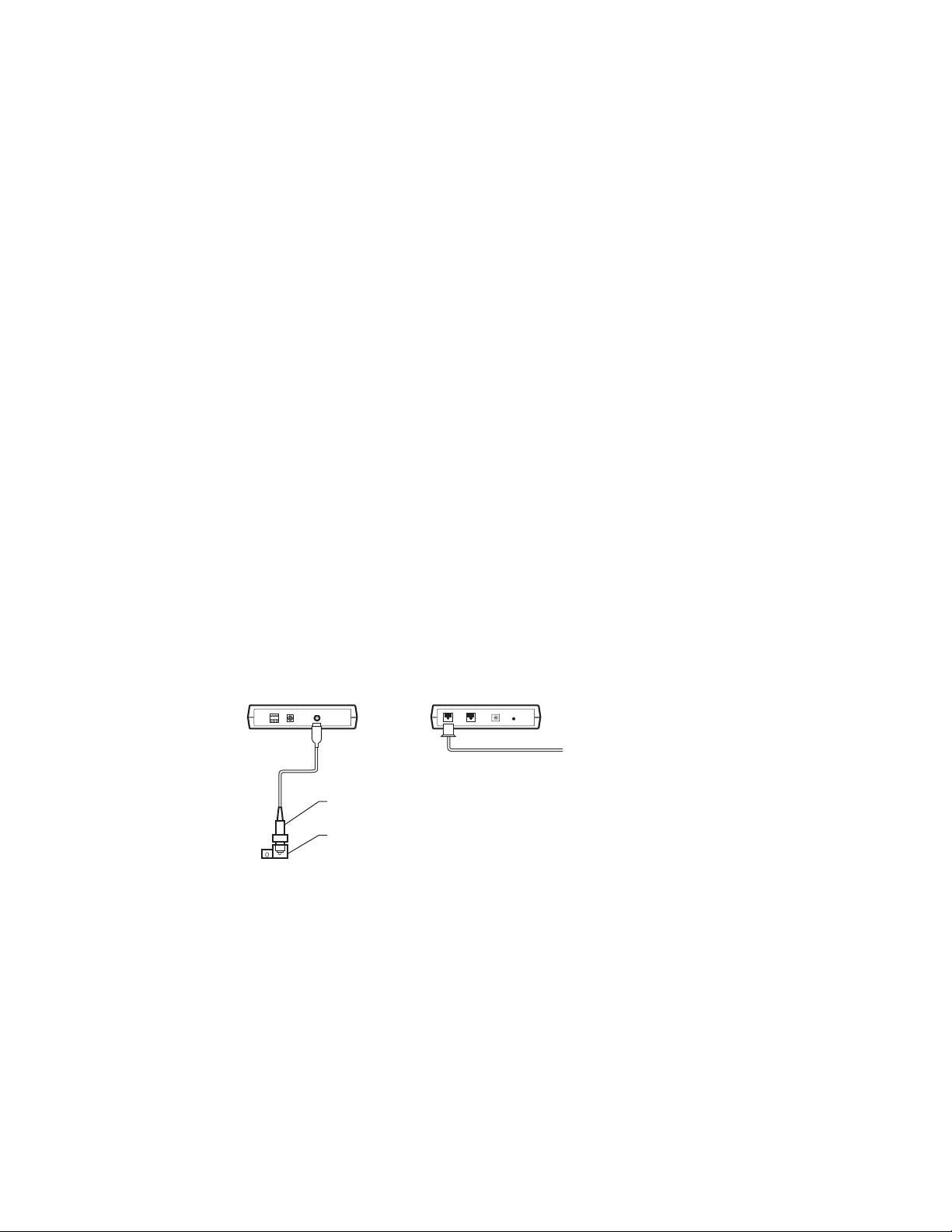
Figure 2. pH Monitor connected via SIM module for BioLogic DuoFlow without a Maximizer system
2
SIGNAL IMPORT MODULE
FRONT VIEW
pH ELECTRODE
pH FLOW CELL
pH MONITOR
REAR VIEW
TO BIOLOGIC CONTROLLER
(HR OR DUO FLOW)
OR
USB BITBUS COMMUNICATOR
Page 3

Figure 3. pH Monitor connected via a DuoFlow Maximizer.
Programming your pH Monitor
See the DuoFlow instruction manual for instructions on programming your pH Monitor.
Calibrating your pH Monitor
The frequency of calibration is a function of the electrode and the solutions it is exposed to. The pH electrode calibration
should be checked daily to assure that its accuracy remains within the range required for your application. Calibration is
done with two standard solutions that span the pH range over which your experiment will be run (for example pH 7 and 4
or pH 7 and 10). Following is a calibration procedure:
Calibration procedure
1. Remove the electrode from the flow cell.
2. Rinse the electrode with deionized water.
3. Place the electrode in the first calibration buffer.
4. From the Utilities drop down menu in the DuoFlow software, select “pH probe calibration”.
5. Enter the temperature from the pH probe calibration screen and reference pH for your first buffer. Press Set.
6. When the pH reading has stabilized, press Okay.
7. Remove the electrode from the buffer and rinse with deionized water.
8. Place the electrode in the second calibration buffer.
9. Enter the reference pH for the second buffer. Press set.
10. When the pH reading has stabilized, press Okay.
Hint: Keep calibration and elution buffers at the same temperature. This will eliminate the need to correct values for
temperature effects. Allow sufficient time for the pH reading to stabilize. In general, buffers at low concentrations
take longer to stabilize. Do not expose the electrode to extreme pH solutions for prolonged periods of time. Doing so
will severely shorten the lifespan of the electrode.
Maintenance of your pH Monitor
All pH electrodes age with time. Aging is characterized by slower speed of response or drifting. Your electrode
should typically have specific voltage readings at different pH’s as specified in the chart below.
Standard solution Voltage
pH 7 0 ± 30 mV
pH 10 -171 ± 30 mV
If your electrode differs significantly from the above reading, clean the electrode according to the following directions. If performance is not restored, then the electrode should be replaced.
3
WORKSTATION
MAXIMIZER
pH ELECTRODE
pH FLOW CELL
pH MONITOR
Page 4

S
cience
a
02 99
800
a
(01)
385 55
91
Canada
C
dFrance
0
65
089 318 8
7
g
85
3300
a
(
ael
590 5200
ea
8
a
ca
305-894-5950
co
52 5 53
ds
d
64-9
30
095 979 98 00
590-5200
Swede
9555
1
US/EG
A
ad
.
Electrode Cleaning
A dirty pH electrode can lead to erroneous pH readings and shorten the lifetime of the electrode. Most contaminant’s will be either proteins that have adsorbed onto the glass membrane or buffer and salt crystals that have
blocked the pH probe pores.
Removal of protein deposits: Immerse the electrode in a 1% solution of proteases, such as trypsin or pepsin, in
0.1M HCl for no more than 5 minutes. Rinse with deionized water to remove all traces of HCl.
Removal of salt deposits: Immerse the electrode in 0.1M HCl for 5 minutes followed by 0.1M NaOH for 5 minutes
and then 0.1M HCl for 5 minutes. Rinse the electrode with deionized water to remove all traces of HCl.
Storing Your pH Electrode Between Uses
When pH readings are made infrequently (i.e., several days or weeks apart), the electrode should be stored in its
plastic bulb filled with electrode storage solution (available from VWR or Orion) or pH 4 buffer in 3.5 M potassium
chloride.
Do Not Allow the Electrode to Dry Out.
Trouble Shooting
Symptom Possible Cause Possible Solution
Noisy or unstable Readings Air bubble on membrane Remove air bubble
Drift Solution temperature is changing Allow all solutions to come to thermal equilibrium.
Leakage around pH probe Loose nut Tighten pH electrode nut
Leakage around pH probe Missing or damaged o-rings Replace o-rings
Leakage around fittings Loose fitting Tighten fitting
Leakage around fittings Cracked or loose ferrule Replace fitting
Technical Assistance
For additional help, contact your local Bio-Rad representative. In the United States, call Chromatography
Technical Support at 1-800-4BIORAD.
Ordering Information
760-2040 DuoFlow pH Monitor
760-2042 pH Electrode
760-2044 Flow Cell
750-0502 Signal Import Module
910-1828 o-ring, pH flow cell, size 2-009
910-3014 o-ring, pH electrode, size 2-018
760-2046 BioLogic pH Monitor tubing kit – for connection between Conductivity flow cell and pH flow cell inlet
includes
1 x 28 cm 1/16” OD x 0.02” ID orange PEEK, rated to 5000 psi
1 x 28 cm 1/16” OD x 0.03” ID green PEEK, rated to 3000 psi
4106525 Rev B
Bio-R
Laboratories, Inc
Life
Group
Web sitewww.bio-rad.com USA(800) 4BIORAD Australi
Hong Kon
tin Ameri
L
ia 7
hina86-10-8201-1366/68 Denmark Finlan
2-2789-
Indi
Mexi
Singapore
91-124) 6398112/113/114 Isr
4 2552 to 54 The Netherlan
-2729877 Spain34-91-
14 2
Austri
03 951 4124 Italy 34 91
n 46 (0)8-55 51 27 00 Switzerland1-717-
-877 89 01 Belgium09-
New Zealan
11 Brazil 55 21 507 61
1 47 95 69
Japan03-5811-6270 Kor
-4152280 47-23-38-41-
United Kingdom
2-2-3473-4460
4-17
-181134
ulletin 0000
Rev
00-000 0000 Sig 010
 Loading...