

Bio-Rad BioLogic DuoFlow Pathfinder 80 System DuoFlow Chromatography System Starter Kit User Manual
Page 1
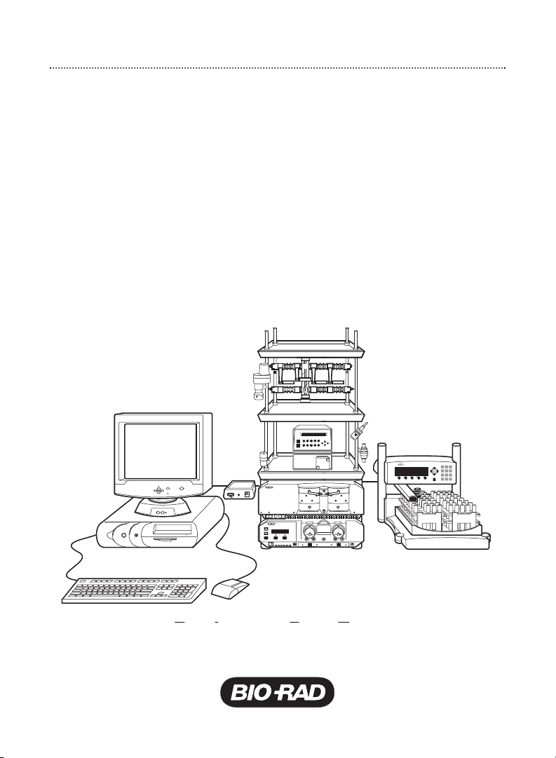
BioLogic DuoFlow
F3 F4 F5
1 2 3
4 5 6
7 8 9
0
F1 F2
A B
VALVE A VALVE B
BioFrac Franction Collector
™
Chromatography System
Starter Kit
Instruction Manual
Catalog # 760-0135
Page 2

Table of Contents
Introduction .......................................................................................1
1. Starter Kit Components ..............................................................1
2. Materials You Will Need...............................................................1
I. BioLogic DuoFlow System ....................................................3
Section 1. DuoFlow System Preparation .........................................3
1.1 Prime the Workstation Pumps.....................................................5
1.2 Move the AVR7-3 Inject Valve to the Purge Position....................5
1.3 Purge the Workstation Pumps ....................................................5
1.4 Manual Control of the Workstation Pumps ..................................6
1.5 Flush the System Through to the Fraction Collector ....................6
BioFrac Fraction Collector
1.6 Turn on the UV Lamp ..................................................................6
DuoFlow UV Detector
QuadTec UV/Vis Detector
1.7 Manual Screen Chromatogram Window......................................7
1.8 Status Bar...................................................................................7
Section 2. Anion Exchange Separation of Protein Standards........8
2.1 Overview of the Procedure..........................................................8
2.2 Prepare Buffers...........................................................................9
2.3 Prepare Sample..........................................................................9
2.4 Install UNO Q1 Column ............................................................10
2.5 Prime the Pumps and Equilibrate the UNO Q1 Column ............10
2.6 Create a New Method...............................................................10
Page 3

II. DuoFlow Maximizer and Pathfinder Systems.....................18
Section 3. System Preparation.......................................................18
3.1 Prime the Workstation Pumps ..................................................20
3.2 Move the AVR7-3 Inject Valve to the Purge Position..................20
3.3 Purge the Workstation Pumps ..................................................21
3.4 Manual Control of the Pumps ...................................................21
3.5 Flush the System Through to the Fraction Collector ..................21
BioFrac Fraction Collection
3.6 Turn on the UV Lamp................................................................22
DuoFlow UV Detector
QuadTec UV/Vis Detector
3.7 pH Electrode Calibration ...........................................................23
3.8 Manual Screen Chromatogram Window ...................................23
3.9 Status Bar ................................................................................24
Section 4. Anion Exchange Separation of Protein Standards ......24
4.1 Overview of the Procedure........................................................24
4.2 Prepare Solutions .....................................................................25
4.3 Prepare Sample........................................................................26
4.4 Install the UNO Q1 Column.......................................................26
4.5 Prime the Pumps and Equilibrate the UNO Q1 Column.............27
4.6 Create a New Method...............................................................29
Section 5. Ordering Information.....................................................36
Page 4

Introduction
This instruction manual and starter kit contents may be used for the BioLogic
DuoFlow system and the BioLogic DuoFlow Maximizer
chromatography systems. The use of the starter kit with these systems is
described in Sections 1 and 3, respectively.
1. Starter Kit Components
This starter kit contains the following items for running a separation:
• 50 ml of buffer A, 250 mM Tris-HCI buffer, pH 8.1 (10x concentrate)
• 50 ml of buffer B, 250 mM Tris-HCI buffer, pH 8.1, plus 5.0 M NaCl (10x concentrate)
• 50 ml of Maximizer solution A1, 500 mM Tris-HCl (10x concentrate)
• 50 ml of Maximizer solution A2, 500 mM Tris base (10x concentrate)
• 50 ml of Maximizer solution B2, 5.0 M NaCl (2.5 x concentrate)
• One vial of anion exchange protein standard (catalog #125-0561)
• One 1 ml disposable sample injection syringe
• One 50 µl sample loop
The chromatographic separation for this kit requires approximately 6 minutes.
2. Materials You Will Need
In order to prepare the starter kit buffer solutions you will need the following
materials:
• Filtered high-quality water (i.e., HPLC grade water)
™
and Pathfinder
™
• One 500 ml graduated cylinder
• One 1 L side-arm flask
• Stirbar and stirplate
• Vacuum source for degassing
• Two 500 ml bottles
• Fraction collection tubes, 13 x 100 mm (at least 14 tubes)
• 100 ml beaker
1
Page 5

If you are using the DuoFlow Maximizer or Pathfinder systems you will also need
the following materials:
• pH 7.00 and pH 10.00 standard buffer
• One 200 ml graduated cylinder (optional)
• Two additional 500 ml bottles
• Fraction collection 1.5 or 2 ml micro tubes
2
Page 6
I. BioLogic DuoFlow System
Section 1. DuoFlow System Preparation
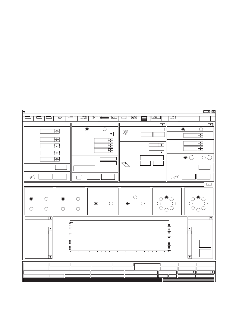
When the DuoFlow system is turned on, the Manual screen is displayed (see
Figures 1 and 2). This screen displays instrument control panels that provide
direct control of the pumps, valves, fraction collector, UV detector, QuadTec
UV/Vis detector, and Econo™Gradient Pump. The arrow button in the upper
right corner of the detector control panel toggles between the UV and QuadTec
detector control panels. Only those instruments connected to the system will be
displayed.
BioLogic Duo-Flow - - - no method -
File View Utilities Options Window Help
New
Method
Flowrate
Inlet A
Inlet B
High
limit
Low
limit
SVT5-4 at port 1 SVT3-2 at port 3SV5-4 at port 2
1
4
UV Conductivity
Zero baseline for the UV detector
New
Edit
Method
Run Browser Manual Setup Setup
Gradient Pump: F10
1.00
50
50
700
0
START
QuadTec
Gradient Pump: F10 UV Conductivity
0.00 ml/min
2
3
50 %B
Report
Fraction Collector: BioFrac
Mode: System
ml/min
%
%
psi.
psi.
Set
STOP
1
4
1.50
1.00
0.50
0.00
AU
F1 (12-13 mm tubes)
Rack:
Start Tube:
End Tube:
Fraction size:
Tube number:
Volume left:
Advance
2
3
100% Buffer B
50
02 46 8
1 psi 0.2583 AU 0.000 mS/cm
Fig. 1. Manual Control Screen with UV detector
wash
1
2
load
Protocol
1
20
1.00
1
START STOP
Workstation Valves
Run
Local
Notes
Conductivity range
(mS/cm):
ml
UV range (AU):
L21
Fractions
Minutes
PostRun
UV Detector
Chart Recorder
AVR7-3 at port 4
I
Econo Gradient
Log
Settings
Zero Baseline
ON OFF
5
1.0
Event Mark
P
Pump
Econo Gradient Pump 1
Mode: System
Flowrate
EGP %B
% Split
Flow
Direction
OFFON
AVR9-8 at port 5
I
82
37
6
4
5
400.0
300.0
200.0
100.0
0.0
10
mS/cm
Flow Rate EGP %B
1.000
0
0.00
START STOP
AVR9-8 at port 6
I
82
6
5
0 %B0.00 ml/min 0%
SIM1/pHSIM1/SIG
™
Bio-Rad
Web
ml/min
%
%
Set
Resize
Clear
Traces
% Split
Local
37
4
3
Page 7
4
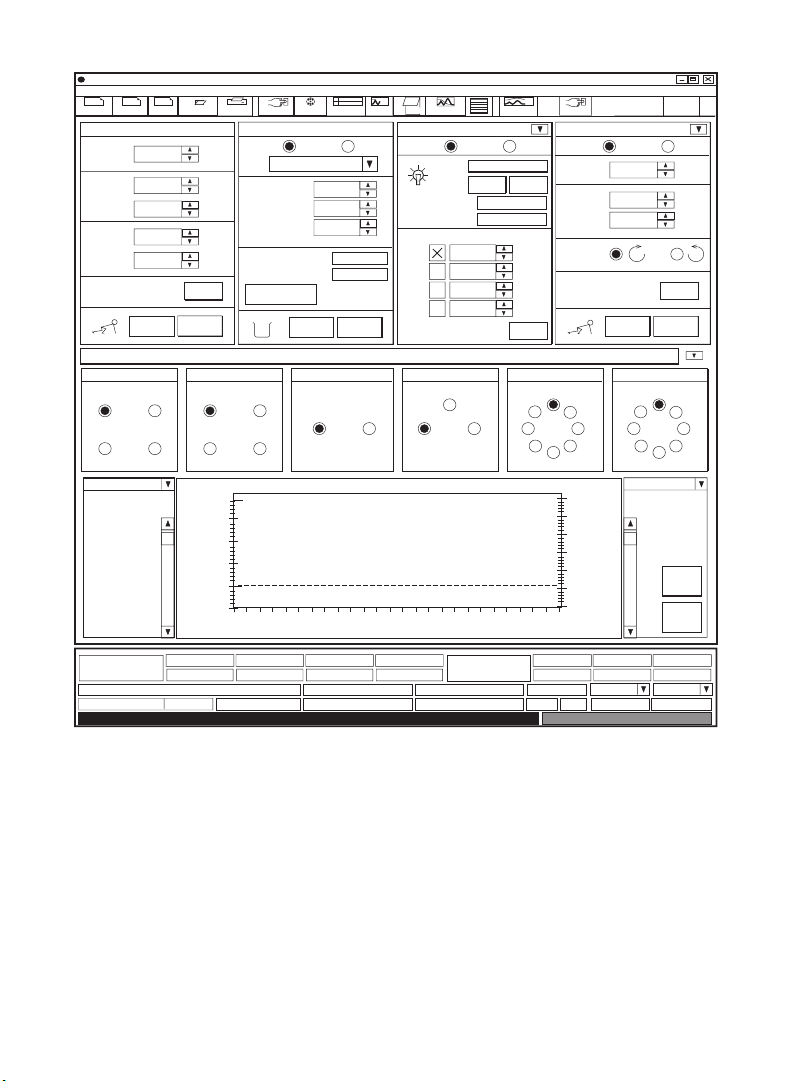
BioLogic Duo-Flow - - - no method -
Fig. 2. Manual Control Screen with QuadTec detector
File View Utilities Options Window Help
New
Method
Flowrate
Inlet A
Inlet B
High
limit
Low
limit
New
Edit
Method
Run Browser Manual Setup Setup
Gradient Pump: F10
1.00
50
50
700
0
START
ml/min
%
%
psi.
psi.
Set
STOP
Report
Fraction Collector: BioFrac
Mode: System
F1 (12-13 mm tubes)
Rack:
Start Tube:
End Tube:
Fraction size:
Tube number:
Volume left:
Advance
wash
1
2
load
Protocol
1
20
1.00
1
START STOP
Notes
Run
Local Mode: System Local
Mode: System Local
Lamp Type
Range
ml
Log
PostRun
Settings
QuadTec Detector
Zero Baseline
ON OFF
Deuterium
190 - 370 nm
Wavelength Selection
280
260
214
405
nm
nm
nm
nm
Set
Econo Gradient Pump 1
Flowrate
1.000
0
EGP %B
% Split
0.00
Flow
Direction
START STOP
Workstation Valves
SVT5-4 at port 1 SVT3-2 at port 3SV5-4 at port 2
1
4
1
2
3
4
UV Conductivity
1.50
1.00
0.50
0.00
AU
QuadTec
0.00 ml/min
Sets fraction collector to system mode
WL1 - 280 nm
0.2232 AU
Gradient Pump: F10
50 %B
2
3
100% Buffer B
50
02 46 8
WL2 - 260nm WL3 - 214nm WL4 - 405nm
0.15 AU 1.15 AU
2 psi 0.2583 AU 0.000 mS/cm
UV
AVR7-3 at port 4
L21
Fractions
Minutes
0.30 AU
I
P
Econo Gradient
Pump
Conductivity
AVR9-8 at port 5
I
82
37
6
4
5
400.0
300.0
200.0
100.0
0.0
10
mS/cm
Flow Rate EGP %B
0 %B0.00 ml/min 0%
AVR9-8 at port 6
82
6
I
5
SIM1/pHSIM1/SIG
Bio-Rad
Web
ml/min
%
%
Set
Resize
Clear
Traces
% Split
37
4
Page 8

1.1 Prime the Workstation Pumps
a. Immerse the workstation pump A and B inlet lines in a container of HPLC
grade (filtered, degassed) or other high quality water.
b. Connect the syringe (supplied with the fittings kit) to the priming port of
pump A.
c. Turn the priming port counter-clockwise one full turn to open the seal. Gently
withdraw the syringe plunger to draw water into the pump head.
d. Repeat this operation several times until no air bubbles are visible in the inlet
tubing.
e. Tighten the priming port by turning it clockwise.
f. Repeat this priming procedure for pump B.
1.2 Move the AVR7-3 Inject Valve to the Purge Position
Prior to purging the pumps at 10 ml/min it is essential to place the AVR7-3 valve
in the purge position. This directs the flow to waste and not to the column and
detector.
To change the position of the AVR7-3 inject valve, select P from the Manual
screen valve control panel for the AVR7-3 valve. If you plugged the AVR7-3 inject
valve into port 4 on the workstation rear panel, you will see a valve box
designated AVR7-3 at port 4. The three buttons of this box correspond to valve
positions as follows: L = Load position, I = Inject position, P = Purge position. To
move the AVR7-3 valve to Purge position, click button P.
The default position at power up and at the end of a programmed method for the
AVR7-3 is L. For all other automated valves the default is position 1.
1.3 Purge the Workstation Pumps
a. Make sure that the AVR7-3 inject valve is in the Purge position.
b. Press the Purge buttons A then B on the front of the workstation. The
workstation pumps will run at a default flow rate of 10 ml/min and the
indicator light will flash green.
c. Run each pump for 2 minutes. Press the purge buttons again to stop the pump.
5
Page 9

6
1.4 Manual Control of the Workstation Pumps
The workstation pump parameters are set from the Manual screen either by
clicking in the appropriate field and entering a value from the keyboard or by
using the arrows. You can set the flow rate between 0.01 to 10 ml/min and the
gradient composition between 0 and 100% B.
To start the pump, click the Start button. Note that the running man icon will start
running. To change the pump parameters while the pump is running, enter the
new value and then click on the Set button.
Pressure limits can be adjusted to match the pressure limits of a column. If the
pressure limit is exceeded, the pump will stop and an alarm will sound. If you are
using an UNO
™
Q1 column, set the high limit to 700 psi and the low limit to 20 psi.
1.5 Flush the System Through to the Fraction Collector
With the gradient pumps stopped, move the AVR7-3 valve back to position L
(Load) by clicking L (AVR7-3) on the Manual screen.
From the gradient pump control panel on the Manual screen, set the pump flow
rate to 1.0 ml/min and start the pump. Water will flow through the UV or QuadTec
and conductivity flow cells to the fraction collector, as described below.
BioFrac
™
Fraction Collector
The BioFrac fraction collector has two operating modes:
• System—Controlled by the DuoFlow system
• Local—Controlled from its own faceplate in stand-alone mode
Ensure that the System button is selected.
When in System mode, the fraction collector control panel will show fields for
Rack type, Start tube, End tube, Fraction size, Tube number, Volume left, a
toggle button for Start and Stop, and a button for Advance (see Figures 1 and 2).
1.6 Turn on the UV lamp
DuoFlow UV detector
a. The UV lamp automatically turns on when you turn on power to the
workstation. The UV lamp can be turned on and off by clicking the On and
Off buttons from the UV detector control panel on the Manual screen
(see Figure 1). Check that the lamp is on; the mercury lamp requires
approximately 30 minutes to warm up.
Page 10

b. Click the Zero Baseline button to zero the UV signal. The Status bar along
the bottom of the screen provides AU output for the detector. Ensure that it
goes to zero when you select the zero baseline option.
QuadTec UV/Vis detector
a. The QuadTec detector should be powered On before starting the BioLogic
software. If the QuadTec detector is not powered up, exit the software,
power up the QuadTec detector and restart the software. When connection
is completed, “SLAVE” appears in the corner of QuadTec faceplate. The
QuadTec appears in its own control panel as shown in Figure 2.
b. From the QuadTec detector control panel on the Manual screen (Figure 2),
set the four wavelengths of the QuadTec detector to 280, 260, 214, and 405 nm.
Select Set. The active wavelengths will appear in the lower screen status bar.
c. Click the Zero Baseline button to zero the four UV/Vis signals. The Status bar
along the bottom of the screen provides AU output for the detector. Ensure
that it goes to zero when you select the zero baseline option.
1.7 Manual Screen Chromatogram Window
A feature of the Manual screen is its ability to display up to eight traces of a
chromatogram; including UV/Vis, pH, conductivity, %Buffer B, and pressure
traces, over a 10-minute interval. This is useful during column equilibration. The
chromatogram window is displayed at the bottom of the screen, under the valve
control panel (See Figures 1 and 2). Features of the chromatogram window
include:
• The time axis is reset automatically at the end of 10 minutes or reset manually by
clicking the Clear Traces button
• The chromatogram window can be enlarged by pressing the Resize button.
• A chromatogram trace may be selected for scaling by using the drop-down
menus on the upper right and left of the display
• The Y-axis scale can be changed using the scroll bars on the right or left of the
display
• The maximum and minimum axis settings can be changed by pressing Settings
on the manual screen toolbar.
1.8 Status Bar
At the bottom of the Manual screen is a status bar that is continually updated
with system parameters.
7
Page 11

Section 2. Anion Exchange Separation of Protein Standards
The starter kit enables you to learn to use the DuoFlow system by programming
and running a separation of a premixed anion exchange standard containing
equine myoglobin, conalbumin, chicken ovalbumin and soybean trypsin inhibitor
using a 1.3 ml UNO Q1 column (catalog #720-0001). Equine myoglobin is not
retained on the UNO Q1 column and elutes in the void volume. Conalbumin,
chicken ovalbumin, and soybean trypsin inhibitor bind to the column and require
increased salt concentrations for elution. Separation requires approximately
6 minutes.
2.1 Overview of the Procedure
Run Conditions
• Buffer A 25 mM Tris-HCl, pH 8.1
• Buffer B 25 mM Tris-HCl, pH 8.1, 0.5 M NaCl
• Flow rate 4.00 ml/min
• Sample volume 50 µl
• UV detection 0.1 AUFS
• QuadTec detection 0.1 AUFS (λ = 280 nm), 0.1 AUFS (λ = 260 nm),
1.0 AUFS (λ = 214 nm), and 0.4 AUFS (λ = 304 nm)
• Conductivity 100 mS/cm
General Procedure
Step 1 Prepare buffer
Step 2 Prepare sample
Step 3 Install the UNO Q1 column
Step 4 Prime the workstation pumps and equilibrate the column
Step 5 Write a method
a. Program the instrument Setup
b. Program the method Protocol
c. Load sample into 50 µl loop
d. Select Run
e. Select Start
8
Page 12

2.2 Prepare Buffers
During solution preparation, wear appropriate laboratory protective clothing
including, eye protection, and gloves. Avoid skin and eye contact with starter kit
solutions. In case solutions come in contact with eyes, rinse immediately with
plenty of water and get medical advice.
Buffer A
a. Empty the contents of the bottle labeled buffer A into a 500 ml graduated
cylinder and add filtered, high-quality water to a 500 ml volume.
b. Place the contents of the graduated cylinder into a 1 L side-arm flask and
drop in a stirbar. Cap the side arm flask, place it on a stirplate and connect it
to a vacuum source. Degas the buffer for approximately 15 minutes with
gentle stirring.
c. When degassing is complete, pour the buffer into a bottle and label it “Buffer A,
25 mM Tris-HCI, pH 8.1”.
Buffer B
Prepare buffer B by following the same procedure for preparation of buffer A.
Label the buffer as “Buffer B = 25 mM Tris-HCl, pH 8.1, 0.5 M NaCl”.
Conversion of Maximizer Solutions to Buffers A and B
The starter kit contains solutions for use with the DuoFlow Maximizer or
Pathfinder systems. These can be converted to buffer A, 25 mM Tris-HCI, pH 8.1,
and buffer B = 25 mM Tris-HCl, pH 8.1, 0.5 M NaCl as follows:
a. Dilute Maximizer solutions A1 and A2 to 500 ml each with filtered water.
b. Combine 150 ml of diluted A1, 100 ml of diluted A2 and the entire contents
of solution B2. Dilute the mixture to 500 ml. Check the pH and adjust to pH 8.1,
if necessary. Degas the solution and label it as “Buffer B, 25 mM Tris-HCI,
pH 8.1, 0.5 M NaCl“.
c. Combine the remaining diluted solutions A1 and A2 with water in a 1:1:2
ratio (i.e., 250 ml each of diluted A1 and A2 with 500 ml water). Check the
pH and adjust it to pH 8.1, if necessary. Degas the solution and label it as
“Buffer A, 25 mM Tris-HCI, pH 8.1”.
2.3 Prepare Sample
a. Remove the aluminum cap from the anion exchange standard vial. Slowly
remove the rubber plug from the vial (the contents may be under vacuum).
9
Page 13

b. Add 1.0 ml of prepared buffer A to the vial.
c. Replace the rubber stopper and gently invert the vial to solubilize the protein
standards.
2.4 Install the UNO Q1 column
Remove the end caps from the UNO Q1 column. Keeping tubing lengths to a
minimum, connect 1/16" tubing from port 4 of the AVR7-3 inject valve to the
column inlet. Connect the column outlet to the bottom of the UV flow cell or to
the QuadTec flow cell. Secure the column in a vertical position.
2.5 Prime the Pumps and Equilibrate the UNO Q1 Column
Ensure the pumps are stopped and the inject valve is in the purge position.
Re-prime and purge pumps A and B as described in Section 1.1 of this manual.
Set the inject valve to position L (Load). Set the flow rate to 2.0 ml/min. Set the
UV range to 0.1 AUFS and the conductivity range to 100 mS/cm.
a. Wash the column with 6.5 ml (5 column volumes) of buffer B at 2 ml/min.
b. Equilibrate the column with 13 ml (10 column volumes) of 100% buffer A.
The conductivity monitor on the status bar should now read ≤ 3 mS/cm.
2.6 Create a New Method
In the Manual screen, select the Browser icon from the tool bar. In the Browser
screen you will enter a user name for your method (refer to page 6-1 of the
DuoFlow instruction manual for more information on the Browser screen)
according to the following steps:
• Select the Browser icon from the tool bar menu
• Select the New icon from the upper left side of the Browser screen
• Select New from the drop-down menu and enter your user name in the dialog
box.
• Click on the Project icon for your user name
• Select New and New Method. Enter your method name (or use default
Method 1)
• Click OK to proceed to the instrument/devices Setup screen
10
Page 14

BioLogic Duo-Flow - <user name> - <project name> - <method name> - <run name>
Edit
File View Utilities Options Window Help
New
Method
New
Edit
Method
Run Browser Manual Setup Delete
Report
Available Devices
Aux Load
Pump
Collector
Fraction
wash
1
load
2
Protocol
Run
Notes
PostRun
Log
Settings
Devices in setup
BioFrac Fraction Collector, Rack: F1 (12-13 mm tubes)
UV Detector
Signal Import Module 2 pH Range: 0.00 to 14.00 pH
Buffer Blender
Detectors
Conductivity Monitor
SV5-4 Valve - Inlet A
SVT3-2
Valve
AVR7-3
Valve
SV3
P
U
M
P
INJECT
SV5-4
Valve
AVR9-8
Valve
SV5-4 Valve - Inlet B
AVR7-3 Valve - Sample Inject Port 4
Gradient Pump: F10
Inlet A:
25 mM Tris-HCl, pH 8.1
Inlet A is assigned to SV5-4 Valve - at Port 1
25 mM Tris-HCl, pH 8.1 plus 0.5M NaCl
Inlet B:
Inlet B is assigned to SV5-4 Valve - at Port 2
Port 1
Port 2
Bio-Rad
Web
QuadTec
WL1 - 280nm
Gradient Pump: F10 UV Conductivity
1.00ml/min
0 %B2
0.40
WL2 - 260nm
AU
0.15
AU
WL3 - 214nm
1.15
AU
438 psi 1.003 AU 1.23 mS/cm
WL4 - 405nm
0.30
AU
Econo Gradient
Pump
Flow Rate EGP %B
0 %B0.00 ml/min 0%
0.548 Volt
% Split
SIM1/pHSIM1/SIG
7.00 pH
Fig. 3. Setup editor
Program the Instrument Setup
In the Setup screen select the instruments and devices to be used for the Starter
Kit method. The icons grouped on the left side of the screen (refer to Figure 3,
Available Devices) show all the instruments and devices that can be connected
to the BioLogic DuoFlow systems.
The list of devices in the right box (Devices in Setup) identifies those devices
selected for use with a specific method. The initial default Devices in Setup are a
UV detector, conductivity monitor, and an AVR7-3 inject valve. These come
11
Page 15

standard with the BioLogic DuoFlow system. The DuoFlow QuadTec system
includes a QuadTec UV/Vis detector in place of a UV detector.
a. Click on the Fraction Collector button in the Available Devices box. A dialog
box will appear asking you to choose the type of collector; i.e., a generic
collector, a Model 2110, or a BioFrac. Click on BioFrac and click the OK
button. You will now see BioFrac fraction collector in the Devices in Setup
box. The F1 Rack (12–13 mm tubes) is automatically selected.
b. If you are using a QuadTec UV/Vis detector, click on the Detectors button in
the Available Devices box. A dialog box will appear asking you to choose a
detector. Select QuadTec and check each of the four wavelength boxes.
Enter the wavelengths: (1) 280 nm, (2) 260 nm, (3) 214 nm, and (4) 405 nm.
Press OK.
c. In the Gradient Pump section of the setup screen enter your buffer names. In the
buffer A field, type in 25 mM Tris-HCI, pH 8.1. In the buffer B field type in 25 mM
Tris-HCI + 0.5 M NaCl, pH 8.1.
d. The Setup is now complete. To save the device setup, choose Save Setup
under the File menu and enter a name for your Setup.
e. You are now ready to program the separation steps for your method. To
program your method, press the Protocol icon on the tool bar.
Program the Method Protocol
a. From the Options pull-down menu, ensure that Use Volume (ml) is selected,
so that the programming base is Volume.
b. Program the separation method listed below and in Figure 4.
• From the left side of the screen, press the fraction collection icon. In
the pop-up window that appears, choose Collect All with a fraction
size of 2.00 ml and a delay of 0.0. Make sure the correct rack type is
displayed.
• Program the remaining steps using the Add Step icons from the left
side of the screen.
12
Page 16

BioLogic DuoFlow - <user name> - <project name> - <method name> - <run name>
File View Utilities Options
Edit
New
Method
Add Step
Isocratic
Flow
Load/Inject
Sample
Linear
Gradient
Change
Valve
Column
Switching
Repeat
Steps
New
Edit
Method
Run Browser Manual Setup
V
Report
0.00
1
0.00
2
1.00
3
1.00
4
5
1.50
2.30
6
7
15.30
18.10
8
26.10
Hold
Pause
Alarm
Zero
Baseline
Lamp
EGP
Fraction
Collection
Window Help
Collection Fractions of size 2.00 ml during entire run
Isocratic Flow
Zero Baseline
Load/Inject Sample
Isocratic Flow
Linear Gradient
Isocratic Flow
Isocratic Flow
wash
1
2
load
Protocol
Notes
Run
A: 25.0 mM Tris pH 8.1
B: 25.0 mM Tris plus 0.5 M NaCI
UV Detector
Sample
Static Loop
A: 25.0 mM Tris pH 8.1
B: 25.0 mM Tris plus 0.5 M NaCI
A: 25.0 mM Tris pH 8.1
B: 25.0 mM Tris plus 0.5 M NaCI
A: 25.0 mM Tris pH 8.1
B: 25.0 mM Tris plus 0.5 M NaCI
A: 25.0 mM Tris pH 8.1
B: 25.0 mM Tris plus 0.5 M NaCI
PostRun
Log
End of Protocol
Settings
100%
0%
Auto Inject Valve
100%
0%
100% --> 50%
0% --> 50%
0%
100%
100%
0%
Cut Copy Paste DeleteEdit
Volume: 1.00 ml
Flow: 4.00 ml/min
Volume: 0.50 ml
Flow: 4.00 ml/min
Volume: 0.80 ml
Flow: 4.00 ml/min
Volume: 13.00 ml
Flow: 4.00 ml/min
Volume: 2.80 ml
Flow: 4.00 ml/min
Volume: 8.00 ml
Flow: 4.00 ml/min
Bio-Rad
Web
QuadTec
WL1 - 280nm
0.40
AU
WL2 - 260nm
0.15
AU
WL3 - 214nm
1.15
AU
WL4 - 405nm
0.30
AU
Maximizer + Gradient Pump: F10 UV Conductivity
1.00ml/min
0 %B2
438 psi 1.003 AU 1.23 mS/cm
Fig. 4. Protocol screen
13
Econo Gradient
Pump
Flow Rate EGP %B
0 %B0.00 ml/min 0%
0.548 Volt
% Split
SIM1/pHSIM1/SIG
7.00 pH
Page 17

Step Number Start (ml) Step
1. 0.0 Collect fractions of size 2.00 ml during entire run
2. 0.0 Isocratic flow with 100% 25 mM Tris-HCI, pH 8.1,
0% 25 mM Tris-HCI, 0.5 M NaCl, pH 8.1
at 4.00 ml/min for 1.0 ml
3. 1.0 Zero Baseline to set UV baseline to 0.0. Select
either UV detector or QuadTec detector.
4. 1.0 Load inject sample, static loop: Inject 0.5 ml
sample at 4.00 ml/min. You will be injecting the
loop size of 50 µl.
5. 1.5 Isocratic flow with 100% 25 mM Tris-HCI, pH 8.1,
0% 25 mM Tris-HCI, 0.5 M NaCl, pH 8.1
at 4.00 ml/min for 0.8 ml
6. 2.3 Linear gradient with 0% to 50% 25 mM Tris,
0.5 M NaCl, pH 8.1 at 4.00 ml/min for 13.0 ml
7. 15.3 Isocratic flow with 0% 25 mM Tris, pH 8.1,
100% 25 mM Tris, 0.5 M NaCl, pH 8.1
at 4.00 ml/min for 2.8 ml
8. 18.1 Isocratic flow with 100% 25 mM Tris, pH 8.1,
0% 25 mM Tris, 0.5 M NaCl, pH 8.1
at 4.00 ml/min for 8.0 ml
9. 26.1 End of protocol
c. When you have finished programming the method, press the toolbar button
RUN. A dialog box will ask you to name the run. Accept the default Run 1
and click the OK button. You will now see the Run screen (see Figure 5).
The Run Screen
a. The toolbar buttons on the left side of the screen enable you to check that
the screen display ranges for UV (see page 8), QuadTec UV/Vis and
conductivity are correctly set and that the gradient pump pressure limits are
appropriate (700 psi high and 20 psi low limit), for the UNO Q1 column.
b. If you have been equilibrating the column while writing the method, you will
notice that the Status Bar is displaying the flow rate and values for UV,
QuadTec UV/Vis, and conductivity detectors. If necessary, you may wish to
14
Page 18

zero the UV or QuadTec UV/Vis trace by clicking on the Zero baseline button
in the appropriate box. This button may be selected at any time.
c. To scale the on-screen chromatogram trace display axes, use the scroll bars
located on the left and right axes of the chromatogram window.
d. To enlarge the view select the Resize button to the right of the
chromatogram display.
Start the Run
a. Ensure that sufficient tubes are in the fraction collector rack (approximately 14).
The drophead will automatically move to tube 1 when the run is started.
b. Ensure that the AVR7-3 valve is in the LOAD position (position L). If it is not,
return to the Manual Screen by clicking the toolbar Manual button and click
on valve position L.
c. Ensure that the 50 µl sample loop is connected to ports 3 and 6 of the inject
valve. Completely fill the loop with protein standard via port 2 using the
syringe and needle provided. Do not remove the syringe from the injection
port after filling the loop or the sample will siphon to waste.
d. To launch the Run, click on the green Start toolbar button. The sample will
be loaded automatically.
e. When the run is finished, the pumps automatically stop and a “Run Finished”
message appears in the bottom right of the status bar.
f. Figures 5 and 6 show typical run screens and chromatograms for this
separation using the UV or QuadTec UV/Vis detectors.
15
Page 19

BioLogic Duo-Flow - Demo Chromatography - Standard UV Detector - Sample Run
File View Utilities Options
Edit
New
Method
New
Edit
Method
Run Browser Manual Setup
Report
Window Help
wash
1
2
load
Protocol
Run
Notes
PostRun
Log
Frac. Collector
Advance
Divert Valve
1324567891011121314
0.100
100.0% Buffer B
Fractions
Collect
Waste
Grad. Pump
High psi
700
Low psi
0
0.075
0.050
-50.0
Set
Chart Recorder
UV Range
1.0
0.025
Settings
Full View
ConductivityUV
50.0
40.0
30.0
20.0
10.0
Bio-Rad
Web
Event
mark
UV Detector
Zero
Baseline
-0.000
00:00:00 00:02:00 00:04:00 00:06:00
AU
Hr:Min:Sec
Protocol: > 1 0.00 Collection Fractions of size 2.00 ml during entire run
QuadTec
Zero
Baseline
Run Time
0:00.0
QuadTec
Run Volume
0.0 ml
WL1 - 280nm
0.2222 AU
Step Time Left Fraction Vol. Left
Econo Gradient
Pump
Flow Rate EGP %B
Maximizer + Gradient Pump: F10 UV Conductivity
0.00ml/min
50 %B
0 psi 0.2583 AU 3.63 mS/cm
Fig. 5. Run Screen (UV detector and conductivity traces)
Valve Info
0.000 Volt
0.0
-10.0
mS/cm
% Split
0 %B0.00 ml/min 0%
SIM1/pHSIM1/SIG
8.05 pH
16
Page 20

BioLogic Duo-Flow - Demo Chromatography - Standard UV Detector - Sample Run
File View Utilities Options
Edit
New
Method
New
Edit
Method
Run Browser Manual Setup
Report
Window Help
wash
1
2
load
Protocol
Run
Notes
PostRun
Log
Frac. Collector
Advance
Divert Valve
1324567891011121314
0.100
100.0% Buffer B
Fractions
Collect
Waste
Grad. Pump
High psi
700
Low psi
0
0.075
0.050
-50.0
Set
Chart Recorder
UV Range
1.0
0.025
Settings
Full View
ConductivityQuadTec (280 nm)
50.0
40.0
30.0
20.0
10.0
Bio-Rad
Web
Event
mark
UV Detector
Zero
Baseline
-0.000
00:00:00 00:02:00 00:04:00 00:06:00
AU
Protocol: > 1 0.00 Collection Fractions of size 2.00 ml during entire run
QuadTec
Zero
Baseline
Run Time
0:00.0
QuadTec
Run Volume
0.0 ml
WL1 - 280nm
0.2223 AU
Maximizer + Gradient Pump: F10
0.00ml/min
50 %B
Fig. 6. Run screen QuadTec UV/Vis traces
0.0
Hr:Min:Sec
Step Time Left Fraction Vol. Left
WL2 - 260nm WL3 - 214nm WL4 - 405nm
0.15 AU 1.15 AU
0.30 AU
Econo Gradient
Pump
Conductivity
0 psi 0.2580 AU 3.63 mS/cm
0.0
-10.0
Valve Info
Flow Rate EGP %B
0 %B0.00 ml/min 0%
0.000 Volt
mS/cm
% Split
SIM1/pHSIM1/SIG
8.05 pH
17
Page 21
II. DuoFlow Maximizer and
Pathfinder Systems
Section 3. System Preparation
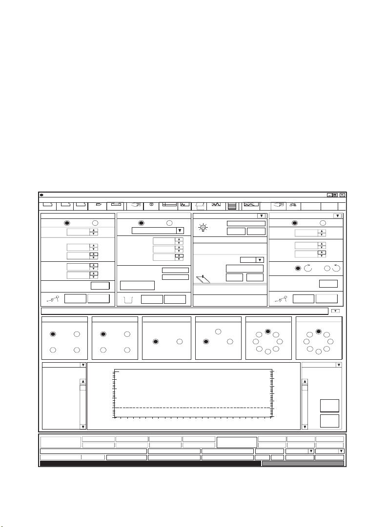
When the DuoFlow Maximizer or Pathfinder system is turned on, the Manual
screen is displayed in either Buffer Blending (Figure 7) or Non-Buffer Blending
mode (Figure 8). This screen displays instrument control panels that provide
direct control of the pumps, valves, fraction collector, UV detector, QuadTec
UV/Vis detector, and Econo gradient pump. The arrow in the upper right corner
of the detector control panel toggles between the UV and QuadTec detector
control panels. The button in the upper right hand corner of the valve control
panel toggles between the workstation and Maximizer valve control panels.
BioLogic Duo-Flow - - - no method -
File View Utilities Options Window Help
New
Method
Maximizer+Gradient Pump: F10
Flowrate
pH
Inlet B
High
limit
Low
limit
SVT5-4 at port 1 SVT3-2 at port 3SV5-4 at port 2
1
4
UV Conductivity
Switch to the QuadTec faceplate
New
Edit
Method
Run Browser Manual Setup Setup
1.00
Tris (25 mM)
8.10
0
700
0
START
QuadTec
Gradient Pump: F10 UV Conductivity
0.00 ml/min
Set
STOP
2
1
4
3
AU
WL1 - 280 nm
0.2225 AU
0 %B2
Report
Fraction Collector: BioFrac
Mode: System
F1 (12-13 mm tubes)
Rack:
ml/min
Start Tube:
End Tube:
%
Fraction size:
psi.
psi.
Tube number:
Volume left:
Advance
2
3
100% Buffer B
1.50
1.00
50
0.50
-0
0.00
02 46 8
1 psi 0.2577 AU 3.63 mS/cm
wash
1
load
2
Protocol
1
20
1.00
1
START STOP
Workstation Valves
Notes
Run
LocalMode: System Local Mode: System Local
ml
UV range (AU):
L21
Fractions
Minutes
PostRun
UV Detector
Chart Recorder
Signal Import Module
SIM 1 is connected
AVR7-3 at port 4
I
Econo Gradient
Log
Settings
Zero Baseline
ON OFF
1.0
Event Mark
P
Pump
OFFON
AVR9-8 at port 5
82
6
Setup
Econo Gradient Pump 1
Flowrate
1.000
0
EGP %B
% Split
0.00
Flow
Direction
START STOP
I
37
4
5
400.0
300.0
200.0
100.0
0.0
10
mS/cm
Flow Rate EGP %B
0 %B0.00 ml/min 0%
0.000 Volt 6.53 pH
AVR9-8 at port 6
I
82
6
5
SIM1/pHSIM1/SIG
Bio-Rad
Web
Set
Resize
Clear
Traces
% Split
ml/min
%
%
37
4
Fig. 7. Manual screen (Buffer Blending mode)
18
Page 22

BioLogic Duo-Flow - - - no method -
File View Utilities Options Window Help
New
Method
Maximizer+Gradient Pump: F10
Mode: System
Flowrate
Composition Inlet Valves
Inl A
Inl B
High
limit
Low
limit
New
Edit
Method
Run Browser Manual Setup Setup
1.00
%
50
%
50
700
0
START
Report
Fraction Collector: BioFrac
Mode: System
Local
ml/min
A1
B1
psi.
psi.
Set
A2
B2
F1 (12-13 mm tubes)
Rack:
Start Tube:
End Tube:
Fraction size:
Tube number:
Volume left:
Advance
STOP
wash
1
load
2
Protocol
1
20
1.00
1
START STOP
Notes
Run
Local Mode: System Local
Mode: System Local
Log
PostRun
QuadTec Detector
Settings
Zero Baseline
Lamp Type
Range
ml
ON OFF
Deuterium
190 - 370 nm
Wavelength Selection
280
260
214
405
nm
nm
nm
nm
Set
Setup
Econo Gradient Pump 1
Flowrate
1.000
0
EGP %B
% Split
0.00
Flow
Direction
START STOP
Workstation Valves
SVT5-4 at port 1 SVT3-2 at port 3SV5-4 at port 2
1
4
1
2
3
4
UV Conductivity
1.50
1.00
0.50
0.00
AU
QuadTec
0.00 ml/min
Switch to the UV faceplate
WL1 - 280 nm
0.2226 AU
Gradient Pump: F10
50 %B
2
3
100% Buffer B
50
-0
02 46 8
WL2 - 260nm WL3 - 214nm WL4 - 405nm
0.15 AU 0.55 AU 0.30 AU
1 psi 0.2580 AU 3.61 mS/cm
UV Conductivity
Fractions
Minutes
AVR7-3 at port 4
I
L21
Econo Gradient
AVR9-8 at port 5
P
Pump
I
82
37
4
6
5
400.0
300.0
200.0
100.0
0.0
10
mS/cm
Flow Rate EGP %B
0.000 Volt 6.54 pH
AVR9-8 at port 6
82
6
0 %B0.00 ml/min 0%
Fig. 8. Manual Screen (Non-Buffer Blending mode)
I
5
Bio-Rad
Resize
Traces
% Split
SIM1/pHSIM1/SIG
Web
ml/min
%
%
Set
37
4
Clear
19
Page 23

3.1 Prime the Workstation Pumps
a. Immerse Maximizer inlet lines A1, A2, B1, and B2 in a container of HPLC
grade (filtered, degassed) or other high-quality water.
b. From the Manual screen place the Maximizer in Local mode and use the
Valve Port Select button, under the A1/A2 Maximizer valve inlet, to select
inlet port A1.
c. Connect the syringe (supplied with the fittings kit) to the priming port of
pump A.
d. Turn the priming port counter-clockwise one full turn to open the seal. Gently
withdraw the syringe plunger to draw water into the pump head.
e. Repeat this operation several times until no air bubbles are visible in the inlet
tubing.
f. Use the Valve Port Select button on the Maximizer to select solution A2.
Gently withdraw the syringe plunger to draw water into the pump head.
g. Repeat this operation several times until no air bubbles are visible in the inlet
tubing.
h. Tighten the priming port by turning it clockwise.
i. Repeat this priming procedure for pump B and inlets B1 and B2.
3.2 Move the AVR7-3 Inject Valve to the Purge Position
Prior to purging the pumps at 10 ml/min it is essential to place the AVR7-3 valve
in the purge position. This directs the flow to waste and not to the columns and
detector.
To change the position of the AVR7-3 inject valve, select P from the Manual
screen valve control panel for the AVR7-3 valve. Select the workstation or
Maximizer valve control panel that displays the AVR7-3 inject valve. For example, if
you have connected the AVR7-3 inject valve into port 10, you will see a valve box
designated AVR7-3 at port 10 of the Maximizer valve control panel. The three
buttons of this box correspond to valve positions as follows: L = Load position,
I = Inject position, P = Purge position. To move the AVR7-3 valve to Purge
position, click button P.
The default position at power up and at the end of a programmed method for the
AVR7-3 is L. For all other automated valves the default is position 1.
20
Page 24

3.3 Purge the Workstation Pumps
a. Make sure that the inject valve is in the Purge position.
b. Select solutions A2 and B2 from the Valve Port Select buttons on the
Maximizer faceplate.
c. Press the Purge buttons A then B on the front of the workstation. The
workstation pumps will run at 10 ml/min and the indicator light will flash green.
d. Run each pump for 2 minutes and then press the Valve Port Select buttons
on the Maximizer faceplate to select solutions A1 and B1. Run each pump
for 2 minutes more and then press the Purge buttons to stop the pumps.
3.4 Manual Control of the Pumps
The workstation pump parameters can be set from the Manual screen
Maximizer+Gradient Pump control panel either by clicking in the appropriate field
and entering a value from the keyboard or by using the arrows. The appearance
of the these control panels depends on whether the instrument is in Buffer
Blending or Non-Buffer Blending mode. Figures 7 and 8 show examples of the
respective Buffer Blending and Non-Buffer Blending control panels. From these
control panels you can set the flow rate, pressure limits, and buffer composition.
You can switch between these two panels by pressing in the toolbar and
checking or unchecking the “Use Buffer Blending” box on the Maximizer Buffer
Blending Setup screen.
To start the pump, click the Start button. Note that the running man icon will start
running. To change the pump parameters while the pump is running, enter the
new value and then click on the Set button. Pressure limits can be adjusted to
match the pressure limits of a column. If the pressure limit is exceeded, the pump
will stop and an alarm will sound. If you are using an UNO Q1 column, set the
high limit to 700 psi and the low limit to 20 psi.
3.5 Flush the System Through to the Fraction Collector
With the gradient pumps stopped, move the AVR7-3 inject valve back to position
L (Load) by clicking L (AVR7-3) on the Manual screen.
From the gradient pump control panel on the Manual screen, set the pump flow
rate at 1.0 ml/min and start the pump. Water will flow through the UV or QuadTec
and conductivity flow cells to the fraction collector, as described below.
21
Page 25

BioFrac Fraction Collector
The BioFrac fraction collector has two operating modes:
• System—Controlled by the BioLogic DuoFlow system
• Local—Controlled from its own faceplate in stand-alone mode
Ensure that the System button is selected.
When in System mode, the fraction collector control panel on the Manual screen
will show fields for Rack type, Start tube, End tube, Fraction size, Tube number,
Volume left, a toggle button for Start and Stop, and a button for Advance (see
Figures 7 and 8).
3.6 Turn on the UV Lamp
DuoFlow UV Detector
a. The UV lamp automatically turns on when you turn on power to the
workstation. The UV lamp can be turned on and off by clicking the On and
Off buttons from the UV detector control panel on the Manual screen (see
Figure 7). Check that the lamp is on; the mercury lamp requires
approximately 30 minutes to warm up.
b. Select the Zero Baseline button to zero the UV signal. The Status bar along
the bottom of the screen provides AU output for the detector. Ensure that it
goes to zero when you select the zero baseline option.
QuadTec UV/Vis Detector
a. The QuadTec detector should be powered On before starting the BioLogic
software. If the QuadTec detector is not powered up, exit the software, power
up the QuadTec detector, and restart the software. When connection is
completed, “SLAVE” appears in the upper left corner of the QuadTec faceplate.
b. From the QuadTec detector control panel on the Manual screen (Figure 7),
set the four wavelengths of the QuadTec detector to 280, 260, 214, and
405 nm. Select Set. The active wavelength will appear in the lower screen
status bar.
c Click the Zero Baseline button to zero the four UV/Vis signals. The Status bar
along the bottom of the screen provides AU output for the detector. Ensure
that it goes to zero when you select the zero baseline option.
22
Page 26

3.7 pH Electrode Calibration
Prior to starting a run the pH electrode should be calibrated as follows:
a. Remove the electrode from the flow cell and rinse it with deionized water.
b. Place the electrode in pH 7 standard buffer.
c. From the Utilities drop-down menu, select “pH probe calibration”.
d. Enter the temperature and reference pH (at the current temperature) for the
first buffer. Press Set. The temperature can be read from the Display Screen
on the Maximizer.
e. When the pH reading has stabilized, press OK.
f. Rinse the electrode with deionized water.
g. Place the electrode in the pH 10 standard buffer.
h. Enter the reference pH for the second buffer at the current temperature.
Press Set.
i. When the pH reading has stabilized, press OK.
3.8 Manual Screen Chromatogram Window
A feature of the Manual screen is its ability to display up to eight traces of a
chromatogram, including UV/Vis, pH, conductivity, % Buffer B, and pressure
traces over a 10-minute interval. This is useful during column equilibration. The
chromatogram window is displayed at the bottom of the screen, under the valve
control panel (See Figures 7 and 8). Features of the chromatogram window
include:
• The time axis is reset automatically at the end of 10 minutes or may be reset
manually by clicking the Clear Traces button
• The chromatogram window can be enlarged by pressing the Resize button
• A chromatogram trace may be selected for scaling by using the drop-down
menus on the upper right and left of the display
• The Y-axis scale can be changed using the scroll bars on the right or left of the
display
• The maximum and minimum axis settings can be changed by pressing Settings
on the manual screen toolbar
23
Page 27

3.9 Status Bar
At the bottom of the Manual screen is a status bar that is continually updated
with system parameters.
Section 4. Anion Exchange Separation of Protein Standards
The starter kit enables you to learn to use the DuoFlow Maximizer or Pathfinder
systems by programming and running separation of a premixed anion exchange
standard containing equine myoglobin, conalbumin, chicken ovalbumin, and
soybean trypsin inhibitor, using a 1.3 ml UNO Q1 column (catalog #720-0001).
Equine myoglobin is not retained on the UNO Q1 column and elutes in the void
volume. Conalbumin, chicken ovalbumin, and soybean trypsin inhibitor bind to
the column and require increased salt concentrations for elution. Separation
requires approximately 6 minutes.
4.1 Overview of the Procedure
Run Conditions
• Buffer A1 50 mM Tris-HCl
• Buffer A2 50 mM Tris base
• Solution B1 deionized water
• Solution B2 2.0 M NaCI
• Flow rate 4.00 ml/min
• Sample volume 50 µl
• UV detection 0.1 AUFS
• QuadTec detection 0.1 AUFS (λ = 280 nm), 0.1 AUFS (λ = 260 nm),
1.0 AUFS (λ = 214nm), and 0.4 AUFS (λ = 304 nm)
• Conductivity 100 mS/cm
• pH pH 7.1 to pH 9.1
General Procedure
Step 1 Prepare solutions A
, A2, B1, and B
1
Step 2 Prepare sample
Step 3 Install the UNO Q1 column
24
2
Page 28

Step 4 Prime the workstation pumps and inlet valves, and equilibrate the
column
Step 5 Write a method
a. Program in the instrument Setup
b. Program the method Protocol
c. Load sample into 50 µl loop
d. Select Run
e. Select Start
4.2 Prepare Solutions
During solution preparation, wear appropriate laboratory protective clothing,
including eye protection and gloves. Avoid skin and eye contact with starter kit
solutions. In case solutions come in contact with eyes, rinse immediately with
plenty of water and get medical advice.
Note: Solutions A, and A
are diluted to 500 ml, solution B2is diluted to 125 ml.
2
Solution A1
a. Empty the contents of the bottle labeled Solution A1 into a 500 ml graduated
cylinder and add filtered, high-quality water to a 500 ml volume.
b. Place the contents of the graduated cylinder into a 1 L side-arm flask and
drop in a stirbar. Cap the side arm flask, place it on a stirplate and connect it
to a vacuum source. Degas the solution for approximately 15 minutes with
gentle stirring.
c. When degassing is complete, pour the buffer into a bottle and label as
"Solution A1 50 mM Tris-HCl".
Solution A2
a. Empty the contents of the bottle labeled Solution A2 into a 500 ml graduated
cylinder and add filtered, high-quality water to 500 ml. Caution: pH of
Solution A2 is approximately 10.5.
b. Place the contents of the graduated cylinder into a 1 L side-arm flask and
drop in a stirbar. Cap the side arm flask, place it on a stirplate and connect it
to a vacuum source. Degas the solution for approximately 15 minutes with
gentle stirring.
25
Page 29

c. When degassing is complete, pour the buffer into a bottle and label “Solution
A2, 50 mM Tris base”.
Solution B1
Place 1 L of water into a 1 L side-arm flask and drop in a stirbar. Cap the side
arm flask, place it on a stirplate and connect it to a vacuum source. Degas the
solution for approximately 15 minutes with gentle stirring. Label solution as
“Solution B1, water”.
Solution B2
a. Empty the contents of the bottle labeled Solution B2 into a 200 ml graduated
cylinder and add filtered, high-quality water to 125 ml. If you mistakenly
dilute solution B
to 500 ml, add 43.8 g NaCI, stir, and degas until dissolved.
2
b. Place the contents of the graduated cylinder into a 1 L side-arm flask and
drop in a stirbar. Cap the side-arm flask, place it on a stirplate, and connect it
to a vacuum source. Degas the solution for approximately 15 minutes with
gentle stirring.
c. When degassing is complete, pour the buffer into a bottle and label it as
“Solution B2, 2 M NaCl”.
4.3 Prepare Sample
a. Using the fraction collector, collect 1 ml of pH 8.1 Tris, 0% B into a tube.
Alternatively, mix 0.25 ml of Solution A1, 0.25 ml of Solution A2, and 0.5 ml
of water in an Eppendorf tube.
b. Remove the aluminum cap from the anion exchange standard vial. Slowly
remove the rubber plug from the vial (the contents may be under vacuum).
c. Add 1.0 ml of the buffer from step (a) to the vial.
d. Replace the rubber stopper and gently invert the vial to solubilize the protein
standards.
4.4 Install the UNO Q1 Column
Remove end caps from the UNO Q1 column. Keeping tubing lengths to a
minimum, connect 1/16" tubing from port 4 of the AVR7-3 inject valve to the
column inlet. Connect the column outlet to the bottom of the UV flow cell or
QuadTec flow cell. Secure the column in a vertical position.
26
Page 30

4.5 Prime the Pumps and Equilibrate the UNO Q1 Column
Ensure the gradient pumps are stopped and the inject valve is in the purge
position. Place the tubing from inlets A1, A2, B1 and B2 into solutions A1 (TrisHCl), A2 (Tris base), B1 (water), and B2 (NaCl), respectively. Re-prime and purge
the pumps and inlets A1, A2, B1, and B2 as described in Section 3.1 of this
manual.
Set the inject valve to position L (Load). Set the flow rate to 2.0 ml/min. Set the
UV (280 nm) range to 0.1 AUFS and the conductivity range to 100 mS/cm.
Set the buffer recipe by pressing on the toolbar and choosing Tris (25 mM)
as your buffer. Press OK. On the manual screen set the pH to 8.10 and the Salt
Molarity %B to 0.0.
Change the pH scale by pressing the Settings button on the toolbar. Set the
minimum pH to 7.1 and the maximum pH to 9.1 in SIM1/pH.
Applying a 1 or 2-point pH correction (optional).
The Maximizer has been designed to prepare buffers accurately and reproducibly
at a user-defined pH and salt composition. The pH accuracy, however, depends
on how close the selected pH is to the buffer systems pKa. In situations where
high pH accuracy is required, you should apply a 1 or 2-point pH correction as
described below.
Single Point Correction (best for isocratic applications)
a. In the manual screen set the pH to 8.1, the salt composition to 0 %B (or to
the desired %B) and the flow rate to 2.0 ml/min.
b. Take the column out of line if it has been connected and start the pump.
c. When the pH has stabilized, read the pH from the status bar or, alternatively,
collect the effluent and measure the pH using a high quality Tris compatible
pH probe.
d. From the buffer blending setup screen, place a check in the Use pH
Correction box (leave the Use Two Point Correction box unchecked).
e. Set the desired pH to 8.1 and the Observed at 0 % pH, to the pH measured
in step (c).
f. Press OK.
27
Page 31

Two-Point Correction (best for gradient applications)
a. In the manual screen, set the pH to 8.1, the salt composition to 0 %B and
the flow rate to 2.0 ml/min.
b. Take the column out of line, if it has been connected, and start the pump.
c. When the pH has stabilized, read the pH from the status bar or, alternatively,
collect the effluent and measure the pH using a high quality Tris compatible
pH probe.
d. Change %B to 100 % (or to the maximum %B that will be used for the
experiment).
e. When the pH reading has stabilized, read the pH from the status bar or,
alternatively, collect the effluent and measure the pH using a high quality Tris
compatible pH probe.
f. Set the %B back to 0% and re-equilibrate the system with the low salt buffer.
g. From the buffer blending setup screen, place a check in the Use pH
Correction box.
h. Set the desired pH to 8.1 and the Observed at 0 %B pH to the pH measured
in step (c).
i. Place a check in the Use Two Point Correction box and set %B to the value
used in step (d)).
j. Set the Observed at %B pH to the pH measured in step (e).
k. Press OK.
Column Equilibration.
a. Connect the UNO Q1 column.
b. Wash the column with 6.5 ml (5 column volumes) of pH 8.10 Tris (100% B) at
2 ml/min.
28
Page 32

BioLogic Duo-Flow - <user name> - <project name> - <method name> - <run name>
Edit
File View Utilities Options Window Help
New
Method
New
Edit
Method
Run Browser Manual Setup Delete
Aux Load
Pump
Buffer Blender
SVT3-2
Valve
AVR7-3
Valve
Maximizer + Gradient Pump: F10
A1: 50 mM Tris-HCl; A2: 50 mM Tris
Inlet A1:
Is assigned to buffer blender
Inlet A2:
Is assigned to buffer blender
B1: Water; B2: 2.0M NaCl
Inlet B1:
Is assigned to buffer blender
Inlet B2:
Is assigned to buffer blender
QuadTec
Gradient Pump: F10 UV Conductivity
1.00ml/min
Available Devices
SV3
P
U
M
P
INJECT
WL1 - 280nm
0.40 AU
0 %B2
Report
Fraction
Collector
Detectors
WL2 - 260nm
0.15 AU
438 psi 1.003 AU 1.23 mS/cm
SV5-4
Valve
AVR9-8
Valve
wash
1
load
2
Protocol
WL3 - 214nm
1.15 AU
Notes
Run
BioFrac Fraction Collector, Rack: F1 (12-13 mm tubes)
Buffer blender: Tris (25mM)
UV Detector
Signal Import Module 1 pH Range: 0.00 to 14.00 pH
Conductivity Monitor
SV5-4 Valve - Inlet A
SV5-4 Valve - Inlet B
AVR7-3 Valve - Sample Inject Port 10
WL4 - 405nm
0.30 AU
PostRun
Log
Econo Gradient
Pump
Settings
Devices in setup
Flow Rate EGP %B
0 %B0.00 ml/min 0%
0.548 Volt
Port 1
Port 2
SIM1/pHSIM1/SIG
7.00 pH
% Split
Fig. 9. Setup editor
c. Equilibrate the column with 13 ml (10 column volumes) of pH 8.10 Tris (0% B).
When finished, the conductivity monitor on the status bar should read
≤ 3 mS/cm.
4.6 Create a New Method
Bio-Rad
Web
In the Manual screen select the Browser icon from the tool bar. In the Browser
screen you will enter a user name and name for your method (refer to page 6-1
of the DuoFlow instruction manual for more information on the Browser screen)
according to the following steps:
• Select the Browser icon from the tool bar menu
• Select the New icon from the upper left side of the Browser screen
• Select New from the drop-down menu and enter your user name in the dialog
box
• Click on the Project icon for your user name
• Select New and New Method. Enter your method name (or use default
Method 1)
• Click OK to proceed to the instrument/devices Setup screen
29
Page 33

Program the Instrument Setup
In the Setup screen, select the instruments and devices to be used for the Starter
Kit method. The icons grouped on the left hand side of the screen (refer to Figure 3,
Available Devices), show all the instruments and devices that can be connected
to the BioLogic DuoFlow systems.
The list of devices in the right box (Devices in Setup) identifies those devices
selected for use with a specific method. The initial default Devices in Setup are a
UV detector, a conductivity monitor, and an AVR7-3 inject valve, as these come
as standard with the BioLogic DuoFlow system. The DuoFlow QuadTec systems
includes a QuadTec UV/Vis detector in place of a UV detector.
a. Click on the Buffer Blending button in the Available Devices box. A dialog box
will appear. Choose Tris (25) mM from the buffer list and select OK. If desired,
enter the 1 or 2-point pH correction measured in Section 4.5.
30
Page 34

BioLogic DuoFlow - <user name> - <project name> - <method name> - <run name>
File View Utilities Options
Edit
New
Method
Add Step
Isocratic
Flow
Load/Inject
Sample
Linear
Gradient
Change
Valve
Column
Switching
Repeat
Steps
Hold
Pause
Alarm
Zero
Baseline
Lamp
New
Edit
Method
Run Browser Manual Setup
Volume Description Parameters
V
1
0.00
2
0.00
3
1.00
4
1.00
5
1.50
2.30
6
7
15.30
18.10
8
26.10
EGP
Fraction
Collection
Report
Window Help
Collection Fractions of size 2.00 ml during entire run
Isocratic Flow
Zero Baseline
Load/Inject Sample
Isocratic Flow
Linear Gradient
Isocratic Flow
Isocratic Flow
End of Protocol
wash
1
2
load
Protocol
Run
pH 8.10
UV Detector
Sample
Static Loop
pH 8.10
pH 8.10
pH 8.10
pH 8.10
Notes
PostRun
0%B
0%B
0%B -> 25%B5
50%B
0%B
Log
Settings
Volume: 1.00 ml
Flow: 4.00 ml/min
Auto Inject Valve
Volume: 0.80 ml
Flow: 4.00 ml/min
Volume: 13.00 ml
Flow: 4.00 ml/min
Volume: 2.80 ml
Flow: 4.00 ml/min
Volume: 8.00 ml
Flow: 4.00 ml/min
Cut Copy Paste DeleteEdit
Volume: 0.50 ml
Flow: 4.00 ml/min
Bio-Rad
Web
QuadTec
WL1 - 280nm
Maximizer + Gradient Pump: F10 UV Conductivity
1.00ml/min
0 %B2
WL2 - 260nm
0.40 AU
0.15 AU
WL3 - 214nm
1.13 AU
438 psi 1.003 AU 1.23 mS/cm
WL4 - 405nm
0.30 AU
Econo Gradient
Pump
Flow Rate EGP %B
0 %B0.00 ml/min 0%
0.548 Volt
% Split
SIM1/pHSIM1/SIG
7.00 pH
Fig. 10. Protocol editor
b. Click on the Fraction Collector button in the Available Devices box. A dialog
box will appear asking you to choose the type of collector; i.e., a generic
collector, a Model 2110, or BioFrac. Click on BioFrac and click the OK
button. You will now see the BioFrac fraction collector in the Devices in
Setup box. The F1 Rack (12–13 mm tubes) is automatically selected.
c. If you are using a QuadTec UV/Vis detector, click on the Detectors button in
the Available Devices box. A dialog box will appear asking you to choose a
detector. Select QuadTec and check each of the four wavelengths boxes.
Enter the wavelengths: (1) 280 nm, (2) 260 nm, (3) 214 nm, and (4) 405 nm.
Press OK.
d. The Setup is now complete. To save the device setup, choose Save Setup
under the File menu and enter a name for your Setup.
e. You are now ready to program the separation steps for your method. To
program your method, press the Protocol icon on the tool bar.
31
Page 35

Program the Method Protocol
a. From the Options pull-down menu, ensure that Use Volume (ml) is selected,
so that the programming base is Volume.
b. Program the separation method listed below and in Figure 10.
• From the left side of the screen, press the fraction collection icon. In the
pop-up window that appears, choose Collect All with a fraction size of
2.00 ml and a delay of 0.0. Make sure the correct rack type is displayed.
• Program the remaining steps using the add step icons from the left side of
the screen.
Step Number Start (ml) Step
1. 0.0 Collect fractions of size 2.00 ml during entire run
2. 0.0 Isocratic flow with 25 mM Tris-HCI, pH 8.1,
0% 1.0 M NaCl, at 4.00 ml/min for 1.0 ml
3. 1.0 Zero Baseline to set UV baseline to 0.0. Select
either UV detector or QuadTec
4. 1.0 Load Inject Sample Static loop: Inject 0.5 ml
sample using 25 mM Tris, pH 8.1,
0% 1.0 M NaCl at 4.00 ml/min
5. 1.5 Isocratic flow with 25 mM Tris, pH 8.1,
0% 1.0 M NaCl at 4.00 ml/min for 0.8 ml
6. 2.3 Linear gradient with 0% to 25% 1.0 M NaCl
at 4.00 ml/min for 13.0 ml
7. 15.3 Isocratic flow at 25 mM Tris, pH 8.1 and
50% 1.0 M NaCl at 4.00 ml/min for 2.8 ml
8. 18.1 Isocratic flow with 25 mM Tris, pH 8.1,
0% 1.0 M NaCl at 4.00 ml/min for 8.0 ml
9. 26.1 End of protocol
c. When you have finished programming the method protocol, press the toolbar
button RUN. A dialog box will ask you to name the run. Accept the default
Run 1 and click the OK button. You will now see the Run screen (see Figures
11 and 12).
32
Page 36

The Run Screen
a. The toolbar buttons on the left side of the screen enable you to check that
the screen display ranges for UV, QuadTec UV/Vis, pH, and conductivity are
correctly set (see page 24) and that the workstation pump pressure limits are
appropriate (700 psi high and 20 psi low limit) for the
UNO Q1 column.
b. If you have been equilibrating the column while writing the method, you will
notice that the Status Bar is displaying the flow rate and values for UV,
QuadTec UV/Vis, and conductivity. If necessary, you may zero the UV or
QuadTec UV/Vis trace by clicking on the Zero baseline button on the
appropriate box. This button may be selected at any time.
c. To scale the on-screen chromatogram trace display axes, use the scroll bars
located on the left and right axes of the chromatogram window.
d. To enlarge the view select the Resize button to the right of the
chromatogram display.
Start the Run
a. Ensure that sufficient tubes are in the fraction collector rack (approximately
14). The drophead will automatically move to tube 1 when the Run is started.
b. Ensure that the AVR7-3 valve is in the LOAD position (position L). If it is not,
return to the Manual screen by clicking the toolbar Manual button and click
on valve position L.
c. Ensure that the 50 µl sample loop is connected to ports 3 and 6 of the inject
valve. Completely fill the loop with protein standard via port 5 and a syringe
and needle. Do not remove the syringe from the injection port after filling the
loop or the sample will siphon to waste.
d. To launch the Run, click on the green Start toolbar button. The sample will
be loaded automatically.
e. When the run is finished, the pumps automatically stop and a “Run Finished”
message appears in the bottom right of the status bar.
f. Figures 12 and 13 show typical run screens and chromatograms for this
separation using the UV detector or QuadTec UV/Vis detector.
33
Page 37

BioLogic Duo-Flow - Demo Chromatography with Buffe... - Standard UV Detector with Buffer Blending - Sample Run
File View Utilities Options
Edit
New
Method
New
Edit
Method
Run Browser Manual Setup
Report
Frac. Collector
Advance
Divert Valve
0.100
Window Help
wash
1
2
load
Notes
Run
Protocol
1324567891011121314
100.0% Buffer B
Fractions
PostRun
Log
Settings
Full View
100.0
ConductivityUV
Collect
Waste
Grad. Pump
High psi
700
Low psi
0
0.075
0.050
-50.0
75.0
50.0
Set
Chart Recorder
UV Range
1.0
0.025
25.0
Bio-Rad
Web
Event
mark
UV Detector
Zero
Baseline
-0.000
-0.0
00:00:00 00:02:00 00:04:00 00:06:00
AU
Hr:Min:Sec
Protocol: > 1 0.00 Collection Fractions of size 2.00 ml during entire run
QuadTec
Zero
Baseline
Run Time
0:00.0
Run Volume
0.0 ml
WL1 - 280nm
0.2223 AU
Step Time Left Fraction Vol. Left
Econo Gradient
Pump
Valve Info
Flow Rate EGP %B
Maximizer + Gradient Pump: F10 UV Conductivity
0.00ml/min
0 %B2
1 psi 0.2577 AU
3.63 mS/cm
Fig. 11. Run screen (UV detector and conductivity traces)
0.0
mS/cm
0 %B0.00 ml/min 0%
0.000 Volt
% Split
SIM1/pHSIM1/SIG
8.05 pH
34
Page 38

BioLogic Duo-Flow - Demo Chromatography with Buffe... - Standard UV Detector with Buffer Blending - Sample Run
File View Utilities Options
Edit
New
Method
New
Edit
Method
Run Browser Manual Setup
Report
Frac. Collector
Advance
Divert Valve
0.100
Window Help
wash
1
2
load
Notes
Run
Protocol
1324567891011121314
100.0% Buffer B
Fractions
PostRun
Log
Settings
Full View
100.0
ConductivityUV
Collect
Waste
Grad. Pump
High psi
700
Low psi
0
0.075
0.050
-50.0
75.0
50.0
Set
Chart Recorder
UV Range
1.0
0.025
25.0
Bio-Rad
Web
-0.0
Event
mark
UV Detector
Zero
Baseline
-0.000
00:00:00 00:02:00 00:04:00 00:06:00
AU
Hr:Min:Sec
Protocol: > 1 0.00 Collection Fractions of size 2.00 ml during entire run
QuadTec
Zero
Baseline
Run Time
0:00.0
QuadTec
Maximizer + Gradient Pump: F10 UV
0.00ml/min
Run Volume
0.0 ml
WL1 - 280nm
0.2219 AU
0 %B2
Step Time Left Fraction Vol. Left
WL2 - 260nm WL3 - 214nm WL4 - 405nm
0.15 AU 1.15 AU
0.30 AU
Econo Gradient
Pump
Conductivity
1 psi 0.2578 AU 3.62 mS/cm
Fig. 12. Run screen (QuadTec UV/Vis detector traces)
0.0
Valve Info
Flow Rate EGP %B
0 %B0.00 ml/min 0%
0.000 Volt
mS/cm
% Split
SIM1/pHSIM1/SIG
6.53 pH
35
Page 39

Section 5. Ordering Information
Catalog # Description
760-0135 Starter Kit
760-0047 BioLogic DuoFlow Standard System, 100/120 V, includes Dell
controller and monitor, USB Bitbus communicator, F10
workstation, MX-1 mixer, 3-tray rack, AVR7-3 sample inject valve,
fittings kit, UV detector with 5 mm flow cell and 254/280 nm filters,
conductivity monitor, BioFrac fraction collector with diverter valve
and two F1 racks, starter kit, UNO Q1 column and instructions
760-2200 BioLogic Maximizer Kit, 110/120 V, includes Maximizer base unit,
pH electrode and flow cell, Maximizer mixer, starter kit, tubing kit,
system cable 30, US power cord
760-1300 BioLogic QuadTec Detector Kit, includes QuadTec detector with
3 mm PEEK flow cell, Instrument control module (ICM, System
cable 25, 26, and 17 (QuadTec RS-232, ICM power, and bus
communication), US power cord, instructions
741-0002 BioFrac Fraction Collector, includes a 110 V power cord, rack
F1(2), Econo system cable #15, and fittings kit
Collection Tubes*
223-9500 1.5 ml Capless Micro Test Tubes, polypropylene, natural, 500/box
223-9750 13 x 100 mm Clear Polystyrene Test Tubes, 1,000/box
223-9750 13 x 100 mm Natural Polypropylene Test Tubes, 1,000/box
* Additional tubes sizes are available from Bio-Rad. Contact your
local Bio-Rad representative for a liquid handling catalog.
36
Page 40

Bio-Rad Laboratories, Inc.
2000 Alfred Nobel Dr., Hercules, CA 94547 USA
510-741-1000
1-800-424-6723
4006208 Rev. B
For technical service, call your local Bio-Rad office, or in the U.S., call
1-800-4BIORAD (1-800-424-6723)
 Loading...