

Page 1

NETWORK
ACP PILOT
INSTALLATION &
COMMISSIONING
MANUAL
BROOKES & GATEHOUSE LTD
Premier Way
Abbey Park
Romsey
Hampshire SO51 9DH
England
Tel: (+44) 01 794 518448
Fax: (+44) 01 794 518077
Page 2

SECTION 1 SYSTEM UNITS
SECTION 1 SYSTEM UNITS................................................................1
SITING THE ACP UNIT..................................................................4
MOUNTING PROCEDURE............................................................4
ACP REMOTE COMPASS UNIT..........................................................5
DESCRIPTION...................................................................................5
SITING THE COMPASS UNIT.......................................................6
MOUNTING PROCEDURE............................................................6
NETWORK PILOT DISPLAY................................................................7
SITING THE PILOT DISPLAY HEAD.............................................8
MOUNTING PROCEDURE............................................................8
NMEA INTERFACING .......................................................................9
NMEA INPUT .................................................................................9
NMEA OUTPUT ...........................................................................10
HAND-HELD CONTROLLER .............................................................11
DESCRIPTION.................................................................................11
SITING THE HAND-HELD UNIT..................................................11
MOUNTING PROCEDURE..........................................................11
MAN OVERBOARD BUTTON (MOB) ................................................12
DESCRIPTION.................................................................................12
SITING THE MAN OVERBOARD ALARM BUTTON...................12
MOUNTING PROCEDURE..........................................................12
ACP JOYSTICK ..................................................................................13
DESCRIPTION.................................................................................13
SITING THE JOYSTICK UNIT .....................................................13
MOUNTING PROCEDURE..........................................................14
RUDDER REFERENCE UNIT (RRU)..................................................15
DESCRIPTION.................................................................................15
Key Points When Installing The RRU...........................................16
LINEAR FEED BACK UNIT................................................................20
1 - 1
Page 3
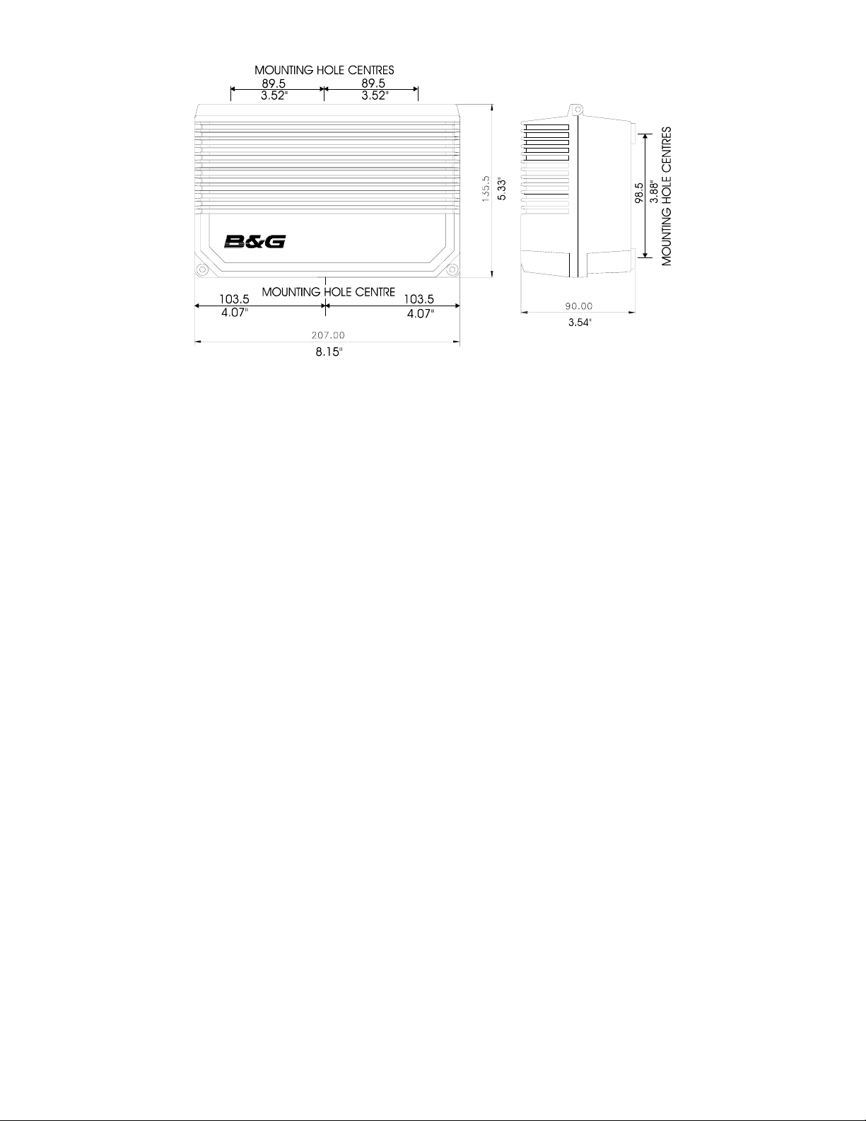
ADVANCED CONTROL PROCESSOR UNIT
DESCRIPTION
The Advanced Control Processor (ACP) Unit contains all the electronics
for the autopilot operation and control of the rudder drive options. It is
designed to be mounted on a vertical, flat , smooth surface. The unit
has a hinged lid to provide easy access to the electrical connections
within. The unit requires the ACP Compass Unit (see next section).
The ACP Unit is available in two configurations:
ACP 1 12V only 12 amps max. output current
ACP 2 12/24V 25 amps max. output current
1 - 2
Page 4

The 12V ACP 1 Unit will control the following rudder drive options:
Size 1/12V Hydraulic Ram Drive RAM-T1-12V blue
•
Size 1/12V Hydraulic Pump PMP-T1-12V blue
•
12V Rotary Drive Unit RDU-T1-12V
•
Stern Drive Unit SDU-T1-12V
•
The 24V ACP 2 unit will control the following rudder drive options:
•
Size 1/12V Hydraulic Ram Drive RAM-T1-12V blue
•
Size 2/12V Hydraulic Ram Drive RAM-T2-12V blue
•
Size 3/24V Hydraulic Ram Drive RAM-T3-24V blue
•
Size 1/12V Hydraulic Pump PMP-T1-12V blue
•
Size 2/12V Hydraulic Pump PMP-T2-12V blue
•
Size 3/24V Hydraulic Pump PMP-T3-24V blue
•
12V Rotary Drive Unit RDU-T1-12V
•
24V Rotary Drive Unit RDU-T3-24V
•
Stern Drive Unit SDU-T1-12V
•
1 - 3
Page 5

SITING THE ACP UNIT
It is recommended that the ACP unit is mounted with the cable entry
•
points downwards. It must not be mounted with the cable entries
uppermost as water may run down the cables and into the unit.
Ensure that there is sufficient space to allow the unit to be hinged
•
open to make connections to terminals inside, and that the hinges of
the two halves of the case may be slid apart.
Select a position sheltered from the direct effects of the environment
•
and from physical damage.
Do not mount the unit within 1m/3ft of engines, starter motors and
•
cables, and other cables carrying heavy current, etc., or 3m/10ft of
Radar or SSB installation cables.
MOUNTING PROCEDURE
Undo the two screws at the corner of the unit, and open fully.
•
The hinges are designed to come apart. This enables the electronics
•
to be split from the base of the unit i.e. the connection and terminal
blocks.
Disconnect the cables between the two halves of the casing.
•
Firmly push the two halves of the computer unit apart.
•
Using the base of the unit as a template, mark the positions of the
•
three mounting screw holes.
Using the self-tapping screws provided secure the base of the unit in
•
position.
Push the two halves of the unit together again and reconnect the
•
cables.
1 - 4
Page 6
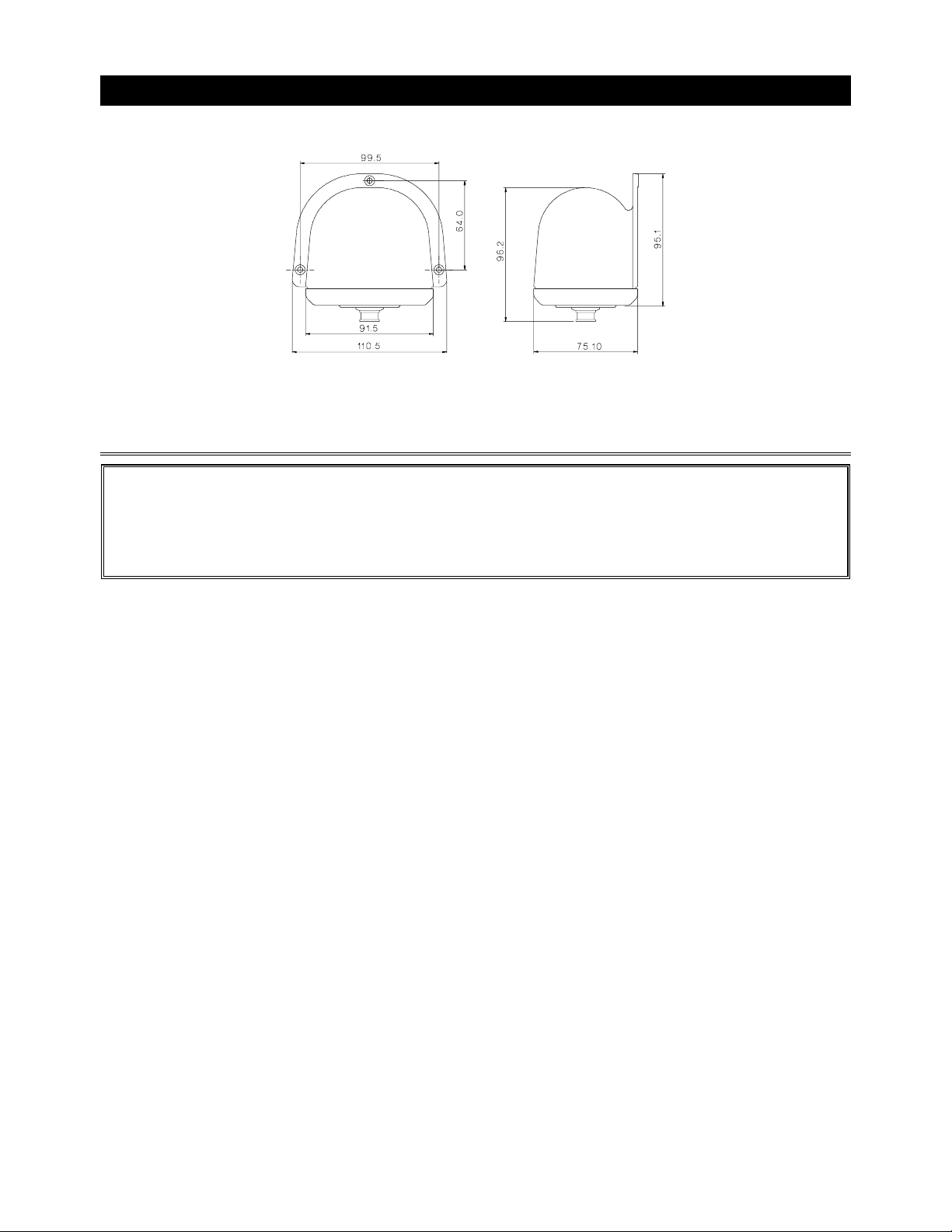
ACP REMOTE COMPASS UNIT
DESCRIPTION
IMPORTANT NOTE:
This external fluxgate compass unit can
ONLY
be used with ACP Pilot Systems or Network Compass displays.
Remove the transit screw after mounting on bulkhead and before
inserting cable connector.
The ACP Remote Compass Unit is a gimbal mounted electronic
fluxgate for use with ACP Pilot Systems. The unit is housed in a sealed
casing constructed of high impact plastic. It is therefore suitable for on
or below deck mounting.
If installed in a vessel with a steel or reinforced concrete hull it may be
necessary to install the external compass unit outside the magnetic
screening affect of the hull and super-structure.
It is supplied with a 12m/36ft, 6-core screened cable, one end with a
sealed connector for the compass unit and the other connecting directly
into the ACP Unit.
1 - 5
Page 7

SITING THE COMPASS UNIT
Mount the unit upright on a flat, vertical bulkhead.
•
A safe distance from external magnetic interference:
•
1m/3ft from VHF, RDF, loudspeakers, depth sounders, engines,
•
power cables carrying heavy current, etc.,
3m/10ft from Radar and SSB Equipment.
•
Reasonably well protected from direct physical damage.
•
With the connector downwards as shown in the above diagram.
•
MOUNTING PROCEDURE
Secure the unit in the selected site using the non-magnetic self-
•
tapping screws provided.
Route the cable to the computer unit avoiding other cables
•
carrying heavy currents, e.g. engine starter, trim tab, etc.
Secure in place with cable clips or tie-wraps.
•
Avoid bending the cable through a tight radius especially near the
•
connector as this may damage the wires inside the cable.
1 - 6
Page 8
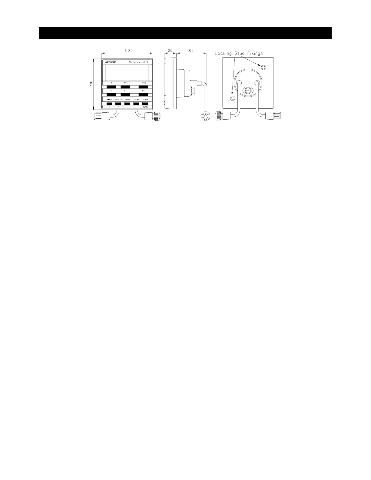
NETWORK PILOT DISPLAY
DESCRIPTION
The Network Pilot Display is designed to be mounted above or below
deck. The display head allows control of the autopilot and by installing
multiple display heads, gives control at any station. It can be connected
to all other Network Instruments via the network cable tails to provide an
integrated autopilot and navigational system. It is essential that the
autopilot is initialised before operation, details are given in the
commissioning section of this manual.
In an integrated system boat speed is supplied from Network SPEED or
QUAD units and wind speed and wind angle from Network WIND via
the system network for Steer to Compass and Steer to Vane modes.
Boat speed can also be set using the display head when required.
Plus
When a GPS
the Pilot via the network cable connection. Without a GPS
is included in the system all required data is carried to
Plus
on the
system, NMEA 0183 (v1.5) data can be input to the Pilot via the 3 pin
socket located on the rear of the display unit.
The display heads are supplied with a clip-in mounting bracket which
allows for easy installation, access from behind is not necessary to
secure the unit in place. However to prevent theft or if removal of the
unit is not required then locking studs and thumb-nuts are supplied to
allow for permanent fixing.
1 - 7
Page 9

SITING THE PILOT DISPLAY HEAD
All Network Instruments are designed for mounting on or below deck.
Select a display site that is:
At a convenient position within easy reach of the helmsman
•
On a smooth and flat surface
•
At a compass safe distance 100mm (4")
•
Reasonably well protected from physical damage
•
Accessible from behind for fitting locking studs if required
•
The rear boss of the unit has a breather hole to prevent
•
condensation, protect the rear cover from direct splashes of water.
MOUNTING PROCEDURE
• Use the cutting template supplied to mark the centres of the holes
for the self-tapping screw, the fixing stud holes and the mounting
bracket.
• The template allows 4mm (5/32") between adjacent units or
118mm/ 4 11/16” between centres for the suncover. Increase this
distance if required to maximum of 60mm (2 3/8") between units or
180mm (7 1/8") between centres.
• For greater distances between units extension cables are available.
• Use a 70mm (2 3/4") diameter hole-cutter for the mounting bracket
hole.
• Use a 2.9mm(1/8”) drill for the self-tapping screws.
• Use a 5mm (3/32") drill for the locking stud holes.
• Secure the mounting bracket to the bulkhead with the self-tapping
screws supplied.
• Fit the rubber sealing gasket around the mounting bracket.
• Screw the locking studs into the back of the display head.
• Carefully pass the cable tails through the mounting bracket hole,
connect the power, interconnecting and NMEA input cables to the
display head (if fitted).
1 - 8
Page 10

• Clip the display head into the mounting bracket.
• Secure the display head with the thumb nuts supplied (if required).
NMEA INTERFACING
The Network PILOT can be interfaced to any NMEA 0183 (v1.5)
compatible position fixer. If more than one source of NMEA data is to be
used then it will be necessary to use two Network PILOT display units.
NMEA INPUT
The Network PILOT display head has an NMEA input connector at the
rear, use a special 3m NMEA input cable 612-OA-053 (Red sig+, Blue
sig-).
The Network PILOT uses the follow data from NMEA:
Cross Track Error (XTE), Speed Over Ground (SOG), Bearing: current
position to destination waypoint, Bearing: origin waypoint to destination
waypoint, Distance: current position to waypoint
Waypoint number
The following NMEA sentences are decoded, Note $ID is any NMEA
talker:
$IDAPA XTE, bearing origin to destination waypoint
$IDAPB XTE, bearing origin to destination waypoint,
bearing to waypoint
$IDRMB XTE, bearing and distance to waypoint
$IDXTE XTE
$IDVTG Speed over Ground
$IDBWR Bearing and Distance to waypoint rhumb,
waypoint number
$IDBWC Bearing and Distance to waypoint great circle,
waypoint number
1 - 9
Page 11

NMEA OUTPUT
NMEA output is via the network cable connection tail, use a special 3m
NMEA output cable 610-OA-030 (Red sig+, Blue sig-).
Dependent on system devices, the following sentences are transmitted:
$IIHDM Heading
$IIVHW Speed and heading
$IIDBT Depth below transducer
$IIVWR Apparent wind angle and speed
$IIMTW Water temperature
1 - 10
Page 12
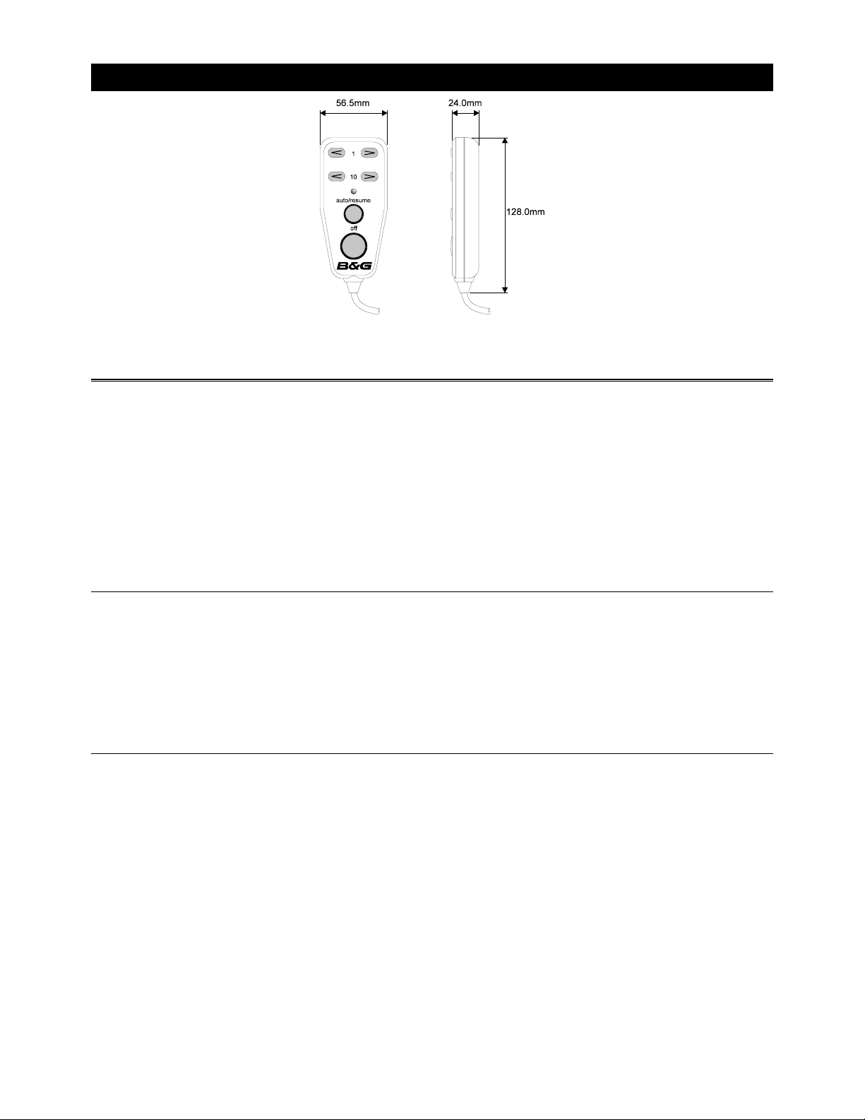
HAND-HELD CONTROLLER
DESCRIPTION
The hand-held remote controller is a waterproof unit that has six
function buttons and a status LED to indicate the operating mode of the
autopilot. The unit provides palm-of-the-hand control of the PILOT. The
cable has a 10 metres /30ft straight section, plus a coiled length that
extends from 1 metre to 3 metres.
SITING THE HAND-HELD UNIT
At a convenient position within easy reach of the helmsman.
•
Ensure at all times the hand-held remote controller's cable does not
•
become snagged on any moving parts e.g. throttle controls.
MOUNTING PROCEDURE
Heavy duty self-adhesive Velcro strip is supplied with the unit.
•
Clean and de-grease the site, stick the Velcro firmly in place.
•
1 - 11
Page 13
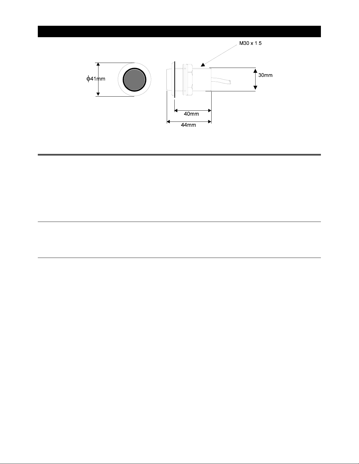
MAN OVERBOARD BUTTON (MOB)
DESCRIPTION
The man overboard alarm button (MOB) is a large red waterproof switch
with 15 metres/45ft of two-core screened cable. This button starts the
MOB sequence of operations when pressed and the audible alarm
sounds (if fitted).
SITING THE MAN OVERBOARD ALARM BUTTON
Select a suitable bulkhead, easily accessible in an emergency.
•
MOUNTING PROCEDURE
With a 32mm (1 1/4") hole-cutter cut a clearance hole for the button
•
body.
Remove the nut and washer, then ensuring the sealing gasket is in
•
place to prevent leakage, carefully feed the cable through the hole.
From behind the bulkhead, fit the washer and nut and tighten.
•
1 - 12
Page 14
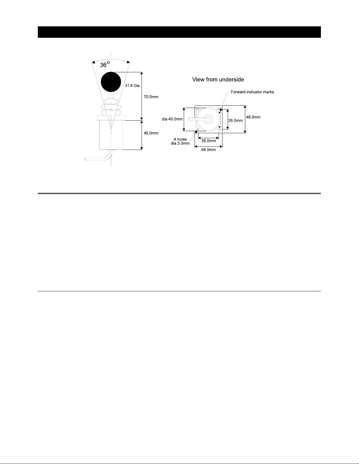
ACP JOYSTICK
DESCRIPTION
The joystick allows direct control of the vessel's rudder via the autopilot
control electronics. The unit is deck-mountable, allowing it to be used
inside or outside the steering positions. A 10m/30ft 6-core screened
cable connects the unit directly into the ACP Units terminals.
Joystick steering is engaged and disengaged with the separate red
button. The lever can only be moved to port or to starboard.
SITING THE JOYSTICK UNIT
At a convenient position within easy reach of the helmsman.
•
1 - 13
Page 15

MOUNTING PROCEDURE
To ensure correct steering sense the unit is marked with two indents,
•
the unit must be installed with these forward.
The unit requires at least 65mm/2.5" clearance behind the selected
•
mounting position.
Use a 40mm (1 9/16th") hole cutter for the joystick body.
•
Ensure the gasket is fitted under the joystick body flange.
•
Secure in place with self-tapping screws.
•
R oute the cable to ACP unit. Connect as per instruction in Section 4
•
of this handbook.
For details on how to install the controller button refer to the MOB
section.
1 - 14
Page 16
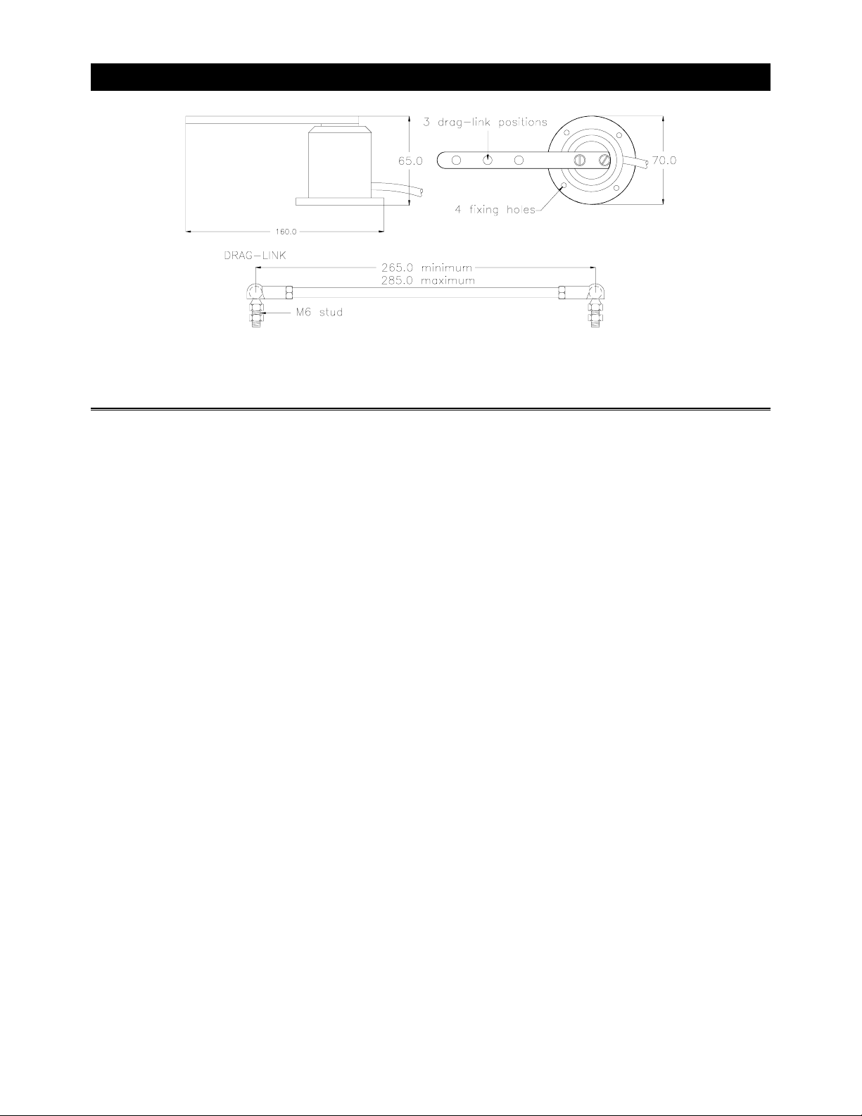
RUDDER REFERENCE UNIT (RRU)
DESCRIPTION
The Rudder Reference Unit (RRU) is a sealed high specification
potentiometer in a robust casing, providing rudder position information
to the Computer Unit. The operating arm is constructed in aluminium
with three positions pre-drilled for the adjustable drag-link. The
drag-link, has ball-joints at each end that connect the unit operating arm
to the tiller arm or steering quadrant. The unit base has four holes to
allow for mounting. The unit is supplied with 10 m/30ft of 3-core
screened cable.
1 - 15
Page 17

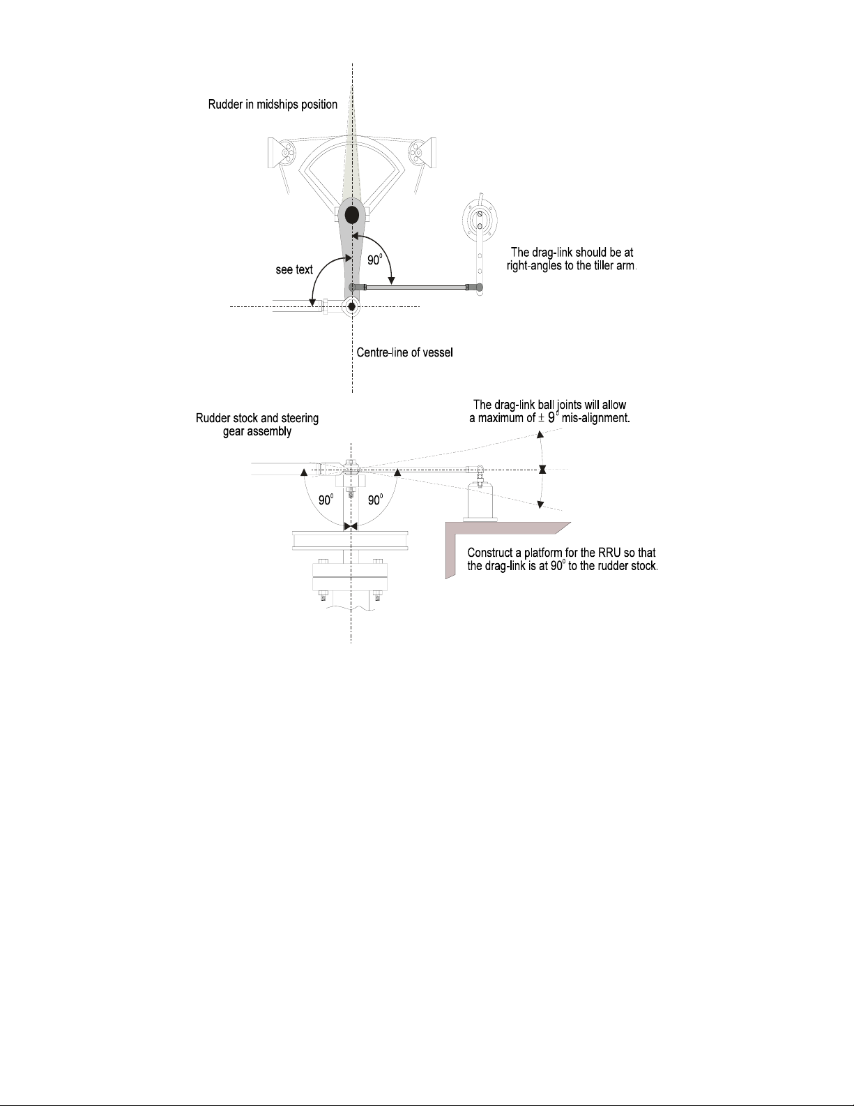
KEY POINTS WHEN INSTALLING THE RRU
General consideration must be given to the steering system and its
•
geometry before starting the RRU installation. Many factors must be
contemplated for a practical solution, the information given here is for
guidance only, although where a maximum or a minimum value is
given these must be adhered to.
Mount the RRU on a flat surface next to the tiller arm or steering
•
quadrant, construct a small platform if necessary.
Do not lengthen the drag-link arm as this can transmit excessive
•
vibration loads to RRU and will invalidate the warranty.
The unit operating arm can be rotated through 360º, the mid-point of
•
the RRU travel is when the operating arm is opposite the cable entry
point.
When the rudder is moved from hard-over port to hard-over starboard
•
the RRU arm should swing through a minimum of 90º, this will ensure
that there is sufficient voltage output to the autopilot. Measure the
voltage difference between the green and blue wires of the RRU,
there should be a minimum of 1 volt change from hard over to hard
over. N.B. If there is less than 1 Volt change the Pilot will not
commission.
After installation check full movement of the steering system ensuring
•
that there is no fouling between the steering gear, RRU parts and
ram drive unit if fitted.
Ensure that there is no backlas h in the linkage between the RRU and
•
the steering gear, otherwise incorrect operation of the autopilot will
occur.
1 - 16
Page 18

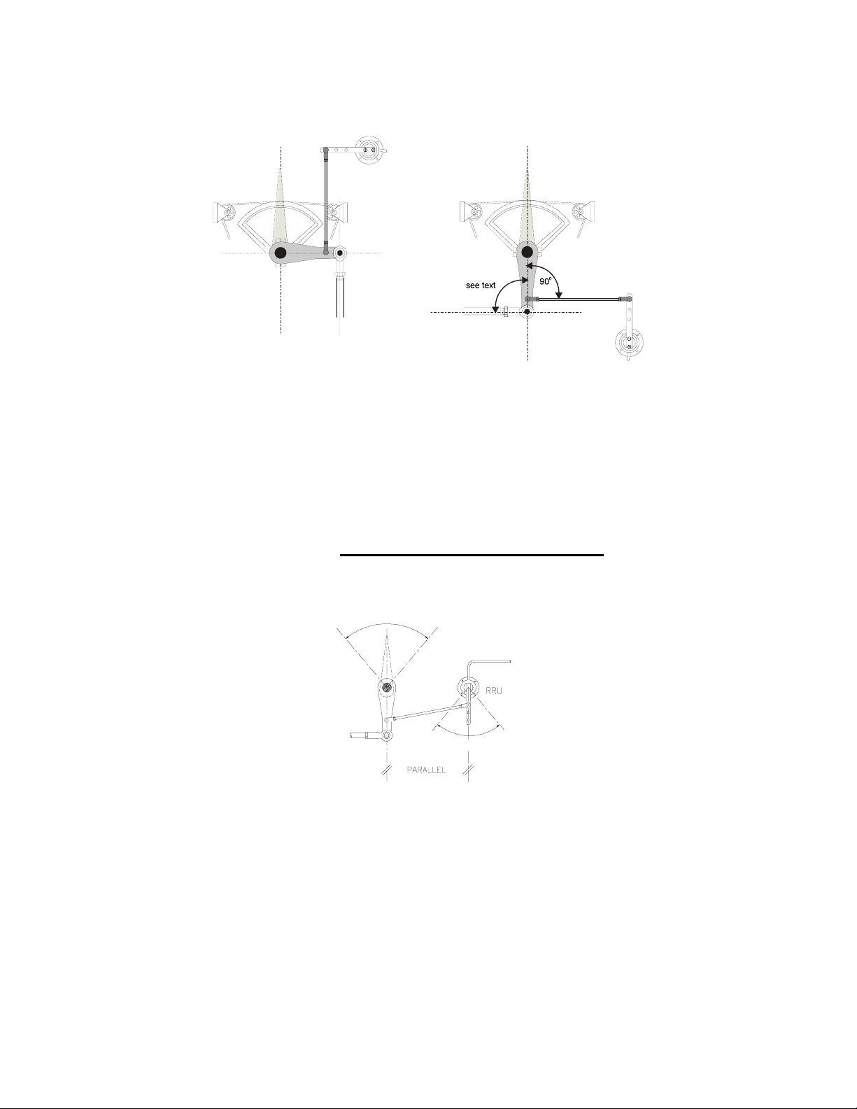
The example shown is a plan view of a typical system with a tiller arm
and quadrant. When viewed in elevation, the ram drive arm and rudder
reference unit drag-link must not be more than ±9º from horizontal.
Ideally everything should be horizontally aligned, this prevents
excessive stress during operation.
1 - 17
Page 19
1 - 18
Page 20
ARIA
The RRU can be mounted in many different positions and orientations
depending on the layout of the steering system.
If the maximum rudder angle is less than 90º then the position of the
RRU or the drag-link must be adjusted so that the operating arm of the
RRU swings through a minimum of 90º and the output voltage
difference is greater than 1 volt from port to starboard lock. Measure the
output of the RRU between the green and blue wires. N.B. If there is
less than 1 Volt difference the Pilot will not commission
.
1V MINIMUM
V
TION
90° MINIMUM RRU AN G LE
1 - 19
Page 21
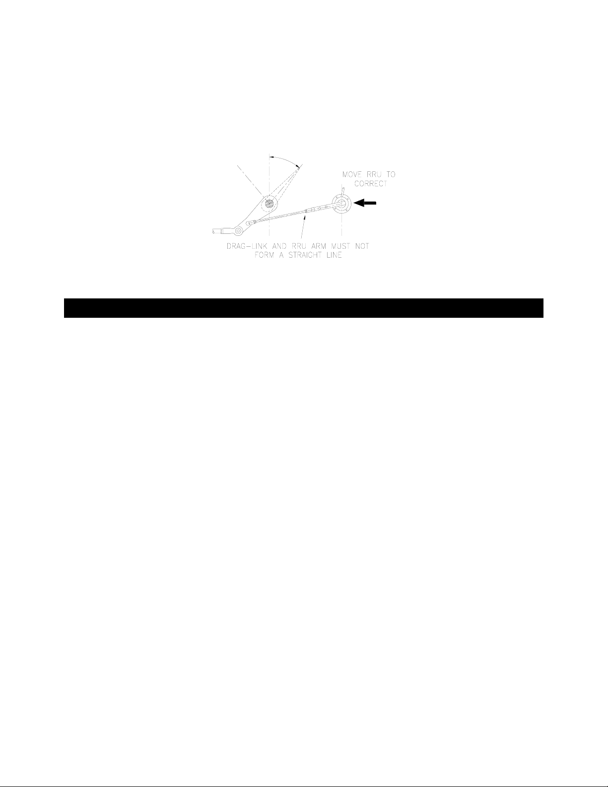
The rudder hard over angle should only be limited by the rudder stops
and not the RRU linkage. Check that when hard over the RRU arm and
drag-link, do not form a straight line. If this occurs the steering system
could become damaged or jammed endangering the boat and crew.
Rectify this immediately by adjusting the position of the RRU.
LINEAR FEED BACK UNIT
Where installation of the conventional Rudder Reference unit is difficult
or physically impossible a Linear Feedback unit can be used. The
Linear Feedback unit comprises of a tube approximately 23mm/ 7/8” in
diameter and 324mm/ 12 3/4” long. This assembly is clamped to the
side of the Linear actuator using a special bracket kit. The Linear Feed
Back shaft is attached to the tiller bracket using the pin supplied with all
Blue rams.
This unit requires careful installation and alignment which should be
carried out by your dealer / supplier. For electrical connection see
section 4.
1 - 20
Page 22

SECTION 2 RUDDER DRIVE OPTIONS
RAM DRIVE UNIT __________________________________2
DESCRIPTION _____________________________________2
BLUE RAMS(DRIVE DATA) __________________________2
SIZE 1 & 2 HYDRAULIC DRIVE PUMP DIMENSIONS _____6
RAM DRIVE UNIT INSTALLATION _____________________7
Key Points On Installation ___________________________8
A Typical Ram Drive Unit Layout (REFER TABLE 2-5) _____9
Ram Mounted Parallel To Vessels Centre-Line __________10
KEY POINTS ON INSTALLATION. ___________________11
MOUNTING A BLUE RAM ON A VERTICAL BULKHEAD__11
SPLITTING THE RAM DRIVE UNIT____________________13
BLUE HYDRAULIC DRIVE PUMPS ___________________14
DESCRIPTION ____________________________________14
Pump Data ______________________________________14
Key Points On Installation __________________________15
HYDRAULIC DRIVE PUMP DIMENSIONS ______________ 16
HYDRAULIC DRIVE PUMP INSTALLATION EXAMPLES__19
2 - 1
Page 23

RAM DRIVE UNIT
DESCRIPTION
A compact DC driven reversible hydraulic pump and hydraulic cylinder
assembly for boats without hydraulic steering systems. Three sizes of
ram drive are available giving a wide thrust range to suit all sizes and
types of vessel.
BLUE RAMS(DRIVE DATA)
Type 1 and type 2 rams combine motor, pump and hydraulic cylinder as
one unit referred to as an actuator. Type 3 rams are supplied split into a
separate motor/pump unit, reservoir and hydraulic cylinder, connected
by 1 metre/ 3ft hoses. Longer hoses are available, contact your dealer.
The units can also be mounted on a vertical bulkhead see page 2-12.
2 - 2
Page 24

RAM
DRIVE
TYPE
ACP UNIT
MOTOR
SUPPLY
SOLENOID
VALVE
SUPPLY
PEAK
THRUST
PEAK
CURRENT
MAXIMUM
STROKE
FULL
BORE
AREA
ANNULUS
AREA
ROD
DIAMETER
TILLER
ARM
for 700
rudder
MAXIMUM
TORQUE
WEIGHT
HELM TO
HELM TIME
extend
retract
RAM SIZE1
BLUE
ACP1 ACP2 ACP2 only ACP2 only
12V DC 12V DC 12V DC 24V DC
12V DC
1.25A (max)
425 kg force
935 lbs-force
14A @
12V
254mm
10"
1208 mmsq,
1.872 "sq
1005
mmsq,
1.558 "sq
16 mm,
0.623 "
214 mm
8.4 "
892 Nm
7867 lb.ins
7 kg,
15 lbs 6oz
15.7 sec
13.4 sec
(8Kg force)
RAM SIZE 1
BLUE
12V DC
1.25A (max)
680 kg
force
1496 lbs-
force
20A @
12V
254mm
10"
1208 mmsq,
1.872 "sq
1005
mmsq,
1.558 "sq
16 mm,
0.623 "
214 mm
8.4 "
1427 Nm
12574 lb.ins
7 kg,
15 lbs 6oz
15.7 sec
13.4 sec
(8Kg force)
RAM SIZE 2
BLUE
12V DC
1.25A (max)
680 kg
force
1496 lbs-
force
25A @
12V
254mm
10"
1208 mmsq,
1.872 "sq
1005
mmsq,
1.558 "sq
16 mm,
0.623 "
214 mm
8.4 "
1427 Nm
12566 lb.ins
7 kg,
15 lbs 6oz
11.9 sec
10.2 sec
(200Kg
force)
RAM SIZE 3
BLUE
24V DC
0.8A (max)
1062 kg
force
2342 lbs-
force
17A @
24V
305mm
12 "
1885 mmsq,
2.921 "sq
1570
mmsq,
2.434 "sq
20 mm,
0.623 "
257
mm
10.16 "
2688 Nm
23780 lb.ins
10.3 kg,
22lbs 11oz
14.6 sec
12.6 sec
(200Kg
force)
The following table may be used to determine the steering system
geometry for different maximum rudder angles and ram type. The last
three columns show the peak torque available (in Kgm), amidships
position and at the maximum rudder angle, with the latter two with the
motor running at 50% duty cycle.
Refer to the diagrams on page 2-6, 2-10, 2-11, 2-13.
2 - 3
Page 25

RA M-T1-12V
568
5
2
1/2 m a x Tiller arm Offs e t Thrus t To rq u e at T o rq u e at Torq u e
rudder angle m m mm (peak m idships midships (at max
a b c Kgf) (peak Kgm) (50% Kgm) 50% Kgm)
25 290 272 425 123 123 118
30 245 227 425 104 104 90
35 214 196 425 91 91 74
40 190 172 425 81 81 62
45 173 155 425 74 74 52
50
RA M-T1-12V
1/2 m a x Tiller arm Offs e t Thrus t To rq u e at T o rq u e at Torq u e
rudder angle m m mm (peak m idships midships (at max
a b c Kgf) (peak Kgm) (50% Kgm) 50% Kgm)
25 290 272 680 197 197 179
30 245 227 680 167 167 144
35 214 196 680 145 145 119
40 190 172 680 129 129 99
45 173 155 680 118 118 83
50 160 142 680 109 109 70
RA M-T2-12V
1/2 m a x Tiller arm Offs e t Thrus t To rq u e at T o rq u e at Torq u e
rudder angle m m mm (peak m idships midships (at max
a b c Kgf) (peak Kgm) (50% Kgm) 50% Kgm)
25
30
35 214 196 680 145 95 77
40 190 172 680 129 84 64
45 173 155 680 118 77 53
50 160 142 680 109 71 4
RA M-T3-24V midstroke = 690mm ACP2 only d= 51mm
1/2 m a x Tiller arm Offs e t Thrus t To rq u e at T o rq u e at Torq u e
rudder angle m m mm (peak m idships midships (at max
a b c Kgf) (peak Kgm) (50% Kgm) 50% Kgm)
25 350 326 1062 372 372 337
30 295 271 1062 313 313 271
35 257 233 1062 273 273 223
40 230 206 1062 244 244 187
45 210 186 1062 223 223 157
50 193 169 106
midstroke = 505mm ACP1 only d= 73.3
160 142 42
midstroke = 505mm ACP2 only d= 73.3mm
midstroke = 505mm ACP2 only d= 73.3mm
290 272 680 197 128 116
245 227 680 167 108 94
205 205 131
68 44
°
°
°
°
2 - 4
Page 26
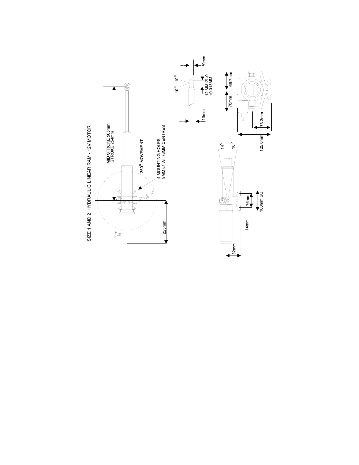
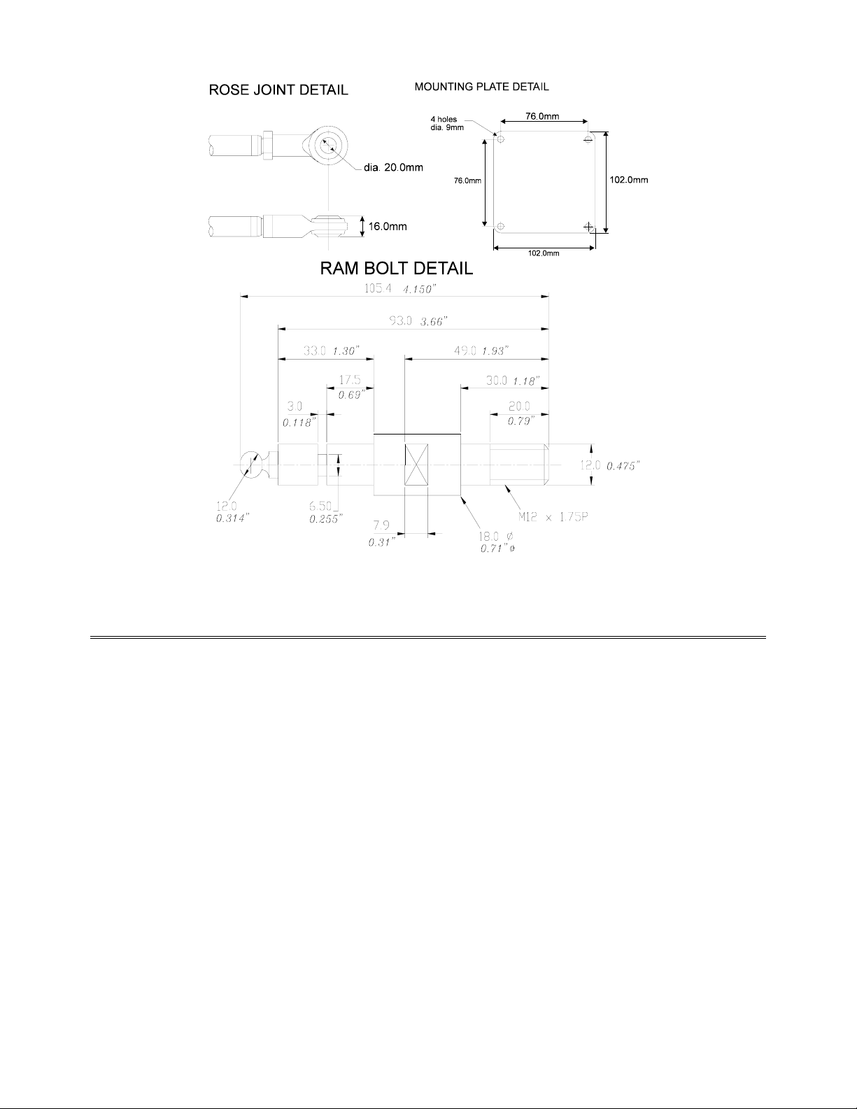
RAM DRIVE UNIT DIMENSIONS - BLUE SIZE 1 AND 2 ACTUATORS
AND BLUE RAMS.
2 - 5
Page 27
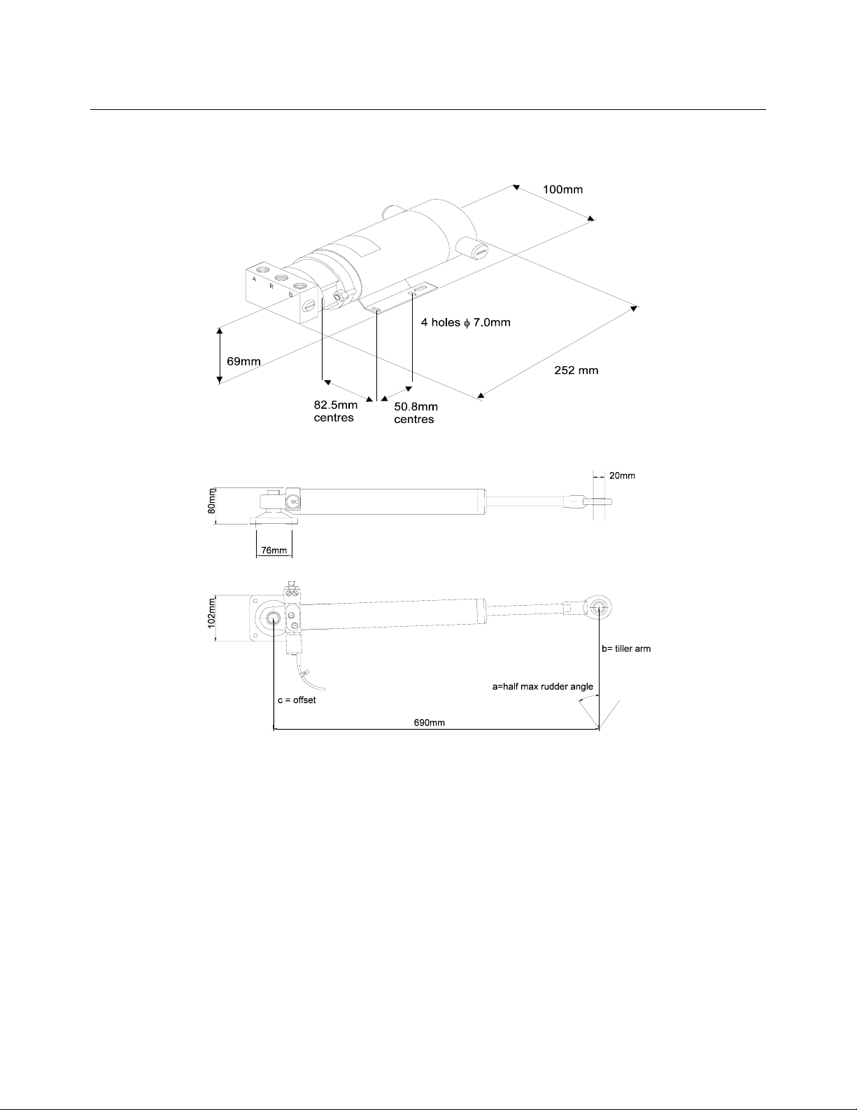
SIZE 1 & 2 HYDRAULIC DRIVE PUMP DIMENSIONS
PUMP AND RAM DRIVE UNIT DIMENSIONS - BLUE SIZE 3
(REFERTO TABLE 2-5)
2 - 6
Page 28
RAM DRIVE UNIT INSTALLATION
General consideration must be given to the steering system and its
geometry before starting the installation. Many factors must be
contemplated for a practical solution, the information given here is for
guidance only, although where a maximum or minimum value is given
this must be adhered to. It is essential that the unit is only installed in a
fully functional steering system, with no backlash or stiffness when
operating. Rectify any steering problems before installation of the ram
drive unit or the autopilot will not function correctly.
2 - 7
Page 29

KEY POINTS ON INSTALLATION
Check that the steering gear is in good condition. Rectify any steering
•
defects prior to installation of the ram.
The ram drive unit must be secured onto a flat, rigid base, it maybe
•
necessary to construct a platform section for the mounting plate. For
angled rudder stocks an angled platform section will have to be
constructed.
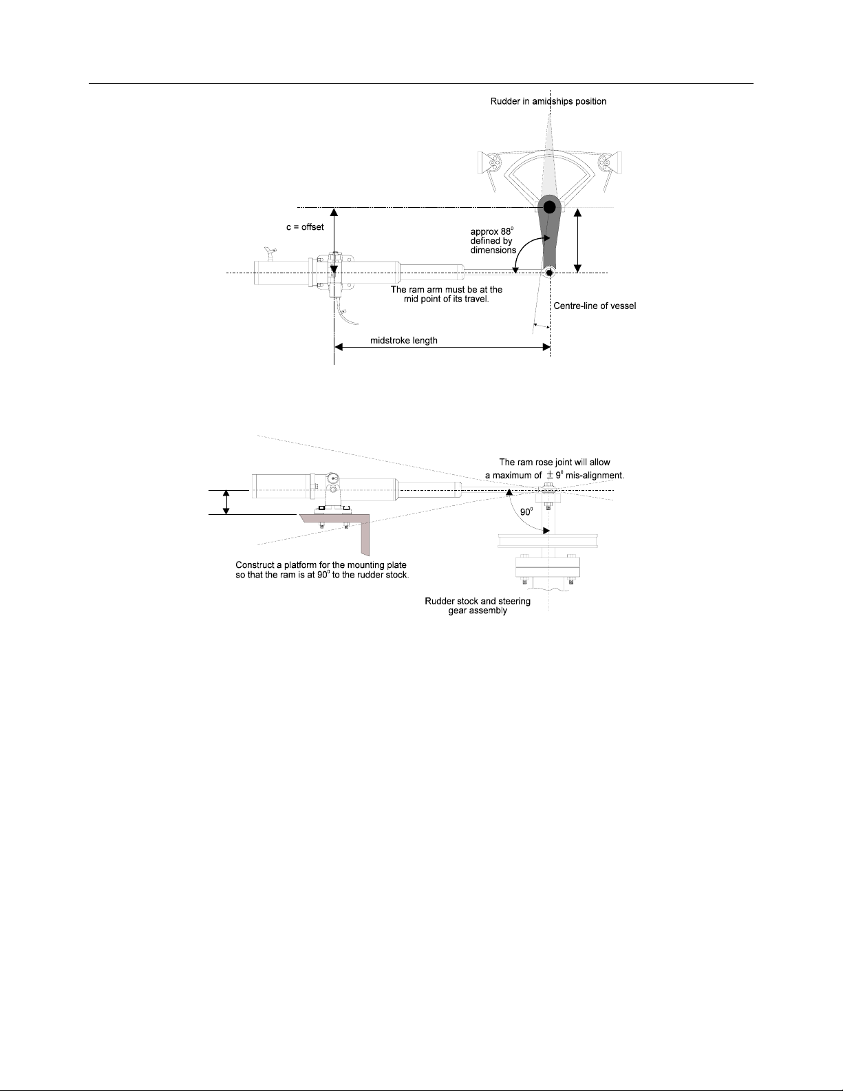
All setting up and aligning of the ram drive unit with the steering
•
system should be carried out with the rudder in the amidships
position and the ram arm at the centre point of its travel.
The angle between the ram arm and the tiller arm should be as
•
shown in the next two diagrams.
The ram arm should ideally be at right-angles to the rudder stock.
•
The ball-joint on the end of the ram arm will allow a
MAXIMUM
of ±9º
of misalignment.
FOR TYPE 3 RESERVOIR INSTALLATION
Do not turn the black reservoir tap on or attempt to move the
piston rod until all of the following are completed:
The base foot of the ram and pump have been bolted into position.
•
The reservoir has been fixed to a bulkhead above the ram and pump.
•
The sealed reservoir transit cap has been replaced by the breather
•
cap supplied.
The reservoir has been filled with the oil supplied.
•
The reservoir tap has been switched to the
•
position allowing the
‘ON’
oil to flow between the reservoir and the pipe.
(TAP ‘ON’ POSITION IS IN LINE WITH THE PIPE)
2 - 8
Page 30
A TYPICAL RAM DRIVE UNIT LAYOUT (REFER TABLE 2-5)
b = tiller arm
length
a=half max rudder angle
d
2 - 9
Page 31

RAM MOUNTED PARALLEL TO VESSELS CENTRE-LINE
(REFER TO TABLE 2-5)
2 - 10
Page 32

KEY POINTS ON INSTALLATION.
•
Make sure that the rudder angle is limited by the rudder stops
and not the limit of travel of the ram arm. Failure to do this will
damage the unit and invalidate the warranty.
Make sure that there is sufficient space at each end for the ram arm
•
to extend fully, the ram stroke length is shown in the table below.
Check for full movement and security of the steering gear before
•
applying any power to the autopilot system, refer to the installation
check list in the commissioning section of this handbook.
MOUNTING A BLUE RAM ON A VERTICAL BULKHEAD
Due to the restricted movement of the ram of +14
°, 10°
for the size 1
and 2 and +/- 5° for the size 3, it is important that the maximum rudder
angle is carefully measured and the positioning of the RAM, tiller arm
length and offset are carefully followed from the diagrams on the next
page.
FAILURE TO COMPLY WITH THESE DIMENSIONS MAY CAUSE
PREMATURE FAILURE OF THE RAM, AND PLACE GREAT
STRESS ON THE STRUCTURE OF THE VESSEL.
The Size 1 and 2
Blue
Ram may be mounted in any orientation, without
the need to fit an external reservoir. The Size 3 Ram requires an
external reservoir which must be mounted above the unit. Care must be
taken to ensure that the connecting pipes are not in anyway kinked or
turned through any tight bends.
2 - 11
Page 33

VERTICAL BULKHEAD INSTALLATION.(REFER TABLE 2-5)
b= tiller arm
5
5
=d
a=half max rudder angle
2 - 12
Page 34

SPLITTING THE RAM DRIVE UNIT
IMPORTANT NOTE:
care must be taken to ensure that a high degree of cleanliness is
observed and no dirt, moisture or foreign objects are allowed to enter
the system. When filling or topping up the external reservoir only use
a good quality ISO 10 hydraulic oil e.g., Q8 DYNOBEAR 10 (10cSt at
40°C)
It is not possible to split linear actuators.
Type 1 and type 2
and hydraulic cylinders connected by hoses, are available from your
dealer. These are supplied with 1 metre hoses. Units with longer hoses
are also available. These can be supplied with quick connect couplings
and pre-filled hoses. Such units do not need to be bled.
Type 3
Units with longer hoses are available from your dealer. These can be
units are supplied as split units, connected by 1 metre hoses.
When dealing with any hydraulic system great
units comprising separate ram/pumps, reservoirs
supplied with quick connect couplings and pre-filled hoses. Such units
do not need to be bled.
2 - 13
Page 35

BLUE HYDRAULIC DRIVE PUMPS
DESCRIPTION
The Reversible Hydraulic Drive Pump has a small high speed pump
driven by a 12 or 24V DC permanent magnet motor. The pump has pilot
check valves to prevent back driving and a pilot operated reservoir
valve to enable the unit to drive balanced or unbalanced cylinders. The
unit has Port and Starboard 1/4" BSP service ports and a 1/4" BSP
reservoir port.
PUMP DATA
HYDRAULIC PUMP
TYPE
PUMP TYPE Reversible
SUPPLY VOLTAGE 12V DC 12V DC 24V DC
TYPICAL OPERATING
CURRENT RANGE
MAXIMUM PRESSURE 1000 psi 1000 psi 1000 psi
MAXIMUM FLOW RATE
at continuous duty motor
loading
CYLINDER CAPACITY 100-300cc,
WEIGHT 3 kg
PMP-T1-12V PMP-T2-12V PMP-T3-24V
Reversible
DC motor
5 to 17.5 Amps 5 to 22.5 Amps 6 to 17.5 Amps
750 cc/min,
46 ins3/min
6.1 to 18.3 in3
6.6 lbs
DC motor
1420 cc/min,
87in3/min
275 to 550cc,
16.8 to 33.6in3
3 kg
6.6 lbs
Reversible
DC motor
1980 cc/min,
121 in3/min
525 to 750cc,
32 to 46in3
4 kg
8.8 lbs
2 - 14
Page 36

KEY POINTS ON INSTALLATION
A position should be chosen convenient for the steering system
hydraulic delivery lines.
The site should be rigid and flat to prevent excess vibration.
•
Shielded from the direct effects of the elements.
•
Minimise the lengths of the hydraulic lines from the pump to the
•
cylinder and where possible the pump motor supply cables.
2 - 15
Page 37

HYDRAULIC DRIVE PUMP DIMENSIONS
Type 1 and 2
Type 3
105mm
(4.13)
4 holes φ 7.0mm
80mm
(3.15)
88.9mm
(3.5)
centres
(0.28)
50.8mm
(2.00)
centres
240 mm
(9.45)
2 - 16
Page 38

HYDAULIC DRIVE PUMP INSTALLATION
IMPORTANT NOTE:
care must be taken to ensure that a high degree of cleanliness is
observed and no dirt, moisture or foreign objects are allowed to enter
the system. When bleeding your hydraulic steering system only use a
good quality ISO10 hydraulic oil e.g. Q8 DYNOBEAR or equivalent
(10cSt at 40° C).
Drain the steering system from the lowest point, usually at a cylinder
1.
coupling.
Fit T-pieces into the port and starboard delivery lines, couple the
2.
lines to the appropriate service ports of the pump using flexible
hydraulic hose.
Couple the reservoir port to the reservoir/balance line from the helm
3.
units. A low pressure, transparent plastic tube can be used. Ensure
that this line rises gradually with no down turns.
When dealing with any hydraulic system great
Refill the steering system as recommended by the manufacturer,
4.
using clean hydraulic fluid.
Fill the cylinder by temporally removing the cylinder couplings and
5.
hoses at each end, refit the hoses securely.
Starting at the highest helm unit, fill the helm reservoir.
6.
Slowly turn the steering wheel two turns to port and then to
7.
starboard, checking the level of fluid in the helm unit reservoir at all
times.
Next turn the wheel fully in one direction until a slight pressure is felt,
8.
continuously monitor the reservoir level.
Repeat in the opposite direction and continue in this manner until
9.
topping up is no longer necessary.
2 - 17
Page 39

10.
When satisfied that the steering is fully bled manually, apply power
to the pump unit.
11.
Turning the wheel fully from lock to lock will cause the pump to self
purge.
12.
Check the fluid level in the helm unit reservoir.
13.
When the system appears to be fully functional, with the pump
running and the helm hard over check for leaks.
14.
Secure all hoses and cables to prevent damage.
2 - 18
Page 40

HYDRAULIC DRIVE PUMP INSTALLATION EXAMPLES
Single Station System Example
Dual Station System Example
2 - 19
Page 41

Dual Station System With Bypass Example
Dual Station Pressurised System Example
2 - 20
Page 42

SECTION 3
ADDITIONAL RUDDER DRIVE OPTIONS
OUTDRIVE DRIVE UNIT____________________________________2
DESCRIPTION ___________________________________________2
OUTDRIVE DRIVE UNIT DATA _____________________________2
MOUNTING BRACKET KITS _______________________________2
OUTDRIVE DRIVE UNIT - DIMENSIONS _____________________3
ROTARY DRIVE UNIT _____________________________________4
DESCRIPTION ___________________________________________4
ROTARY DRIVE DATA____________________________________4
ROTARY DRIVE UNIT DIMENSIONS ________________________5
ROTARY DRIVE SPROCKET WHEEL SELECTION_____________6
3 - 1
Page 43

OUTDRIVE DRIVE UNIT
DESCRIPTION
A compact reversible 12V DC hydraulic pump/reservoir unit with
actuating cylinder for autopilot control of outdrive power-assisted
hydraulic steering systems. Mounting brackets for attaching the cylinder
to the power steer unit depends upon engine type and are listed below.
Other brackets available on request. Mechanical installation instructions
are supplied with the brackets.
OUTDRIVE DRIVE UNIT DATA
PUMP
TYPE
SUPPLY
WEIGHT
MOUNTING BRACKET KITS
VOLVO
STANDARD
VOLVO AQ. D40 345-30-281
MERCRUISER 345-30-282
OMC 345-30-283
YAMAHA 345-30-284
Reversible DC
motor
12V DC
2.7kg
345-30-280
3 - 2
Page 44

OUTDRIVE DRIVE UNIT - DIMENSIONS
3 - 3
Page 45

ROTARY DRIVE UNIT
DESCRIPTION
A compact reversible 12V or 24V DC motor and gearbox, with an
electrically operated clutch acting on the output shaft for autopilot
control of mechanical steering systems. Connection to the steering
system is most commonly via sprocket gears and chain. These to be
supplied by the installer. As a guide the following should be considered
for the drive sprocket:
UK/Euro 13 tooth 3/8" pitch (steel)
USA 10-20 tooth (steel) for Type 40 or 41 chain.
The recommended target hardover to hardover time should be 10 to 12
seconds.
ROTARY DRIVE DATA
SUPPLY VOLTAGE
PEAK OUTPUT TORQUE Type 1
MAXIMUM SHAFT SPEED
TYPICAL POWER CONSUMPTION
CLUTCH SUPPLY
MOUNTING FOOT
WEIGHT
Type 2
The Rotary Drive Unit has a mounting foot that can be
rotated in 45° steps to allow for most installation
requirements.
12V or 24V Options
15 Nm / 132lb ins
45 Nm / 398lb ins
20 rpm
3 to 7 amps
12V or 24V , 1 amp max.
variable in 45° steps
8Kg / 17.64lbs
3 - 4
Page 46

ROTARY DRIVE UNIT DIMENSIONS
3 - 5
Page 47

ROTARY DRIVE SPROCKET WHEEL SELECTION
The number of teeth on the drive sprocket wheel must be chosen to
match each installation. The following guide may be used to select an
appropriate sprocket. The aim is to achieve a hardover to hardover time
of 10 to 12 seconds.
Note:
The Rotary drive has a speed of 20 RPM or 1 revolution per 3
seconds or 3.7 revolutions in 11 seconds
Turn the wheel from hardover port to hardover starboard and count
•
the number of turns of the driven sprocket
number of turns =N
e.g. N = 3.1
Divide 3.7 by N to give the required reduction ratio.
•
ratio = 3.7 / N
e.g.
ratio
= 1.19
Count the number of teeth on the Driven sprocket and divide by the
•
ratio to give the required number of teeth on the Driver sprocket.
driver teeth = driven teeth / ratio
e.g. if driven teeth = 25
driver teeth = 25 / 1.19 = 20.9
Select a sprocket with the number of teeth closest to calculated value
•
e.g. select driver sprocket with
20 teeth
3 - 6
Page 48

Check hardover time using formula:
•
Hardover time = Number of turns of Driven sprocket
x 3 x (Driven teeth/Driver teeth)
e.g. hardover time = 3.1 x 3 x (25/20)= 11.6
The calculated value for the hardover time using a driven sprocket with
25 teeth and a driver sprocket with 20 teeth would be suitable for this
boats steering system.
NOTE:
For larger boats a longer hardover time of up to 15 seconds
may be more appropriate, in this case choose a driver sprocket with
fewer teeth.
3 - 7
Page 49

Section 4 ACP UNIT INSTALLATION
CABLE AND CONNECTION INFORMATION..................................................... 2
EMC COMPLIANCE......................................................................................... 2
G
ENERAL WIRING NOTES
P
ILOT DRIVE UNIT CABLES
All rudder drives - heavy duty power cables................................................. 4
Rams and rotary drives - clutch/valve cables............................................... 4
ACP UNIT TERMINAL DETAILS......................................................................... 5
Wire colour coding and abbreviations..........................................................5
CLUTCH VOLTAGE SELECTION....................................................................... 6
......................................................................................2
....................................................................................4
ACP2 D
NETWORK AND ALARM CONNECTIONS......................................................... 8
REMOTE COMPASS CONNECTIONS................................................................ 9
HANDHELD, MOB AND JOYSTICK.................................................................. 10
HYDRAULIC RAM DRIVE CONNECTIONS...................................................... 11
BLUE RAM SOLENOID WIRING DETAILS ...................................................... 12
HYDRAULIC PUMP CONNECTIONS........................................................ ........ 13
STERNDRIVE DRIVE UNIT CONNECTIONS.................................................... 14
12V/24V ROTARY DRIVE CONNECTIONS ...................................................... 15
CONTINUOUS DRIVE UNIT CONNECTIONS................................................... 16
PROPORTIONAL SOLENOID CONNECTION..................................................17
DIRECT PADDLE INPUT CONNECTION..................................... ..................... 18
IP SWITCH LOCATION
...............................................................................7
LINEAR FEEDBACK CONNECTION ................................................................ 19
-B&G PADDLE CONNECTION.......................................................................... 19
NON-B&G PADDLEWHEEL CONNECTION......................... ............................ 20
4 - 1
Page 50

CABLE AND CONNECTION INFORMATION
EMC COMPLIANCE
B&G equipment is designed to be operated in leisure craft. Every care
has been taken in its design and testing to ensure compliance with the
European EMC Directive, provided it is installed and operated in
accordance with the instructions as supplied, and the units and cables
are used unmodified. Specific attention is drawn to the requirements to
maintain cable separation, where stated.
Transmissions from poorly installed or maintained Single Sideband
equipment may adversely affect the functioning of this equipment. On
vessels fitted with SSB, it is essential that such equipment is installed
following good installation practice and as recommended by the
manufacturer.
GENERAL WIRING NOTES
IMPORTANT NOTE: DO NOT APPLY POWER TO THE PILOT
SYSTEM UNTIL ALL UNITS ARE CONNECTED AND THE WIRING
HAS BEEN CHECKED.
Where spade connectors are supplied always use the correct
•
crimping tool to attach them to the cable. This is extremely important
where high currents are to be passed i.e. rudder drive unit supply
cables.
Keep supply cables as s hort as possible to reduce the possibility of a
•
voltage drop in the cables.
Always fit a fuse or circuit breaker in supply cables. A 25Amp MCB is
•
recommended for the heavy duty power cables.
Clearly identify each cable to prevent incorrect connection.
•
Cables that have a screening braid must have the screen connected
•
as shown on the connection diagrams. The method for connecting
screened cables may vary according to model and are shown in
detail on the accompanying
installation sheet: IS-0777
.
4 - 2
Page 51

All cables should be routed at least 1m / 3ft from cables or
•
components that carry or generate high currents, e.g. alternators,
starter motors and cabling, trim-tab cables, etc.
To minimise interference avoid routing Network cables alongside
•
high power radio or Radar cables, allow 3m/10ft spacing, or within
1m/3ft of engine starter motors and cables and other cables carrying
heavy current.
To prevent damage to cabling always secure in position using cable
•
clips or tie-wraps. Where cables pass through bulkheads always
protect the cable from chafing by fitting grommets.
Do not allow cables to rest in bilges where prolonged immersion in
•
water, fuel, etc. could occur.
Always fit splash covers and lids on processors, computer units and
•
junctions boxes, where supplied.
4 - 3
Page 52

PILOT DRIVE UNIT CABLES
ALL RUDDER DRIVES - HEAVY DUTY POWER CABLES
TOTAL
CABLE
LENGTH
UPTO
8m/26ft
UPTO
12m/40ft
UPTO
20m/65ft
RAMS AND ROTARY DRIVES - CLUTCH/VALVE CABLES
UPTO
9m/30ft
UPTO
15m/50ft
B&G CABLE
PART No.
135-0A-128 4.0mm² 12 AWG
Not available 6.0mm² 10 AWG
Not available 10.0mm² 7 AWG
135-0C-096 0.5mm² 22 AWG
135-0B-096 0.5mm² 22 AWG
COPPER
AREA
CABLE
GAUGE
4 - 4
Page 53

ACP UNIT TERMINAL DETAILS
NOT
USED
WIRE COLOUR CODING AND ABBREVIATIONS
R
BLK
BL
BR
G
WIRE COLOUR TABLE
Red
Black
Blue
Brown
Green
V
Y
O
W
BLANK
Violet
Yellow
Orange
White
Silver
(Not
Used)
4 - 5
Page 54

CLUTCH VOLTAGE SELECTION
NOTE:
The ACP1 Computer Unit does not have dip switches for clutch
voltage selection. The clutch output voltage is fixed at 12V and is
therefore only suitable for Size 1/12V Rams and pumps and 12V rotary
drives.
The ACP2 Computer Unit can output different clutch/solenoid voltages
depending upon the size of rudder drive unit fitted, the clutch/solenoid
valve is only required for rams or rotary drive units. This is achieved by
setting dip switches on the Computer Drive PCB. Access to the
switches is obtained by removing the 4 screws holding the Computer
PCB in the lid of the Computer Unit, carefully lift the PCB clear.
Set the switches as per the table below. The default setting is 9V,
switch 4 ON, suitable for Size 1/12V Rams and Size 2/12V Rams.
ACP 2:
DIP
CLUTCH
DRIVE
SWITCH
1 24V 24V ROTARY
2 18V SIZE 3/24V
3 12V 12V ROTARY
4 9V SIZE 1/2 12V
VOLTAGE
SIZE/TYPE
RAM
RAMS
(to save power)
4 - 6
Page 55

ACP2 DIP SWITCH LOCATION
NOTE
in the top left-hand corner of the PCB mates together properly.
: When reassembling the computer unit ensure that the connector
4 - 7
Page 56

NETWORK AND ALARM CONNECTIONS
NOT
USED
Cable 612-0A-064 (6 metres)
Cable 135-0A-096
(cut off green wire)
4 - 8
Page 57

REMOTE COMPASS CONNECTIONS
NOT
USED
4 - 9
Page 58

HANDHELD, MOB AND JOYSTICK
NOT
USED
4 - 10
Page 59

HYDRAULIC RAM DRIVE CONNECTIONS
4 - 11
Page 60

BLUE RAM SOLENOID WIRING DETAILS
The following information applies to the Size 1, Size 2 and Size 3 Blue
Rams only.
1. Remove the solenoid wiring connector by unscrewing the centre
screw.
2. Remove the screw from the connector housing.
3. Remove the rubber gasket.
4. Use a small screwdriver through the screw hole to carefully push
against the connector block. This will push the front of the connector
block out ready for wiring.
5. Run the cable through the cable entry in the cover and then connect
as follows: Pin 1 Blue Wire
Pin 2 Brown Wire
6. The cable screen must be cut back and sleeved.
Connect the two halves of the connector back together, tighten the
plastic cable clamp nut, replace the rubber seal and refit the connector
onto the solenoid using the centre screw to fully secure it.
4 - 12
Page 61

HYDRAULIC PUMP CONNECTIONS
12V
Hydraulic Pump
4 - 13
Page 62

STERNDRIVE DRIVE UNIT CONNECTIONS
4 - 14
Page 63

12V/24V ROTARY DRIVE CONNECTIONS
TS1
Heavy Duty
Power Supply
(12V OR 24V)
Black
DRIVE
SUPPLY
DRIVE
SUPPLY
IN
OUT
++
CLU
Bl
Br
ALM
Bl
Br
RBlkBlk R
TS2 TS3
Blk
Blk
Bl
HAND HELD
Y
G
V
Br
W
R
Scr
NET
G
Bl
R
Blk
Y
G
V
Br
W
R
G
W
R
Blk
BOAT
SPEED
Bl
R
MOB
G
R
Bl
RRU
TS4
O/G
O/G
Y
G
W
COMPASS
Bl
R
Bl
R
JOYSTICK
G
Red
25A CIRCUITBREAKER
*NOTE: 12VUNIT, 12V SUPPLY
24V UNIT, 24V SUPPLY
Red
Black
Rudder Reference Unit
Rotary DriveUnit
(12V OR 24V)
4 - 15
Page 64

CONTINUOUS DRIVE UNIT CONNECTIONS
These are general wiring instructions only, showing the installation of
the Computer Unit outputs to drive the continuous drive pump solenoid
valves. The continuous drive pump motor will also require a heavy duty
supply, this is not supplied however suitable units can be obtained from
your dealer. Clutch output is used to control the motor supply.
NOTE: The ram solenoid must be designed to operate at the same
voltage as the pump.
NOT
USED
Black
Brown
Blue
Relay
Continuous
Running Pump
RAM
SOLENOID
Note:
Heavy Duty Relay
Not Supplied
4 - 16
Page 65

PROPORTIONAL SOLENOID CONNECTION
These are general wiring instructions only, showing the installation of
the ACP 2 Computer Unit outputs to drive proportional solenoid valves.
The continuous drive pump motor will also require a heavy duty supply,
this is not shown on this diagram. The clutch output could be used to
control the motor supply, the clutch output is only active while the
rudder is being moved. (See Setting The Rudder Drive Type in Section
5).
TS1
DRIVE
SUPPLY
DRIVE
SUPPLY
IN
OUT
++
RBlk
CLU
Bl
Br
ALM
Bl
Br
RBlk
TS2 TS3
Blk
Blk
Bl
Bl
HAND HELD
Y
Y
G
G
V
V
Br
Br
W
W
R
R
G
NET
W
R
Blk
TS4
G
R
Blk
Bl
R
G
R
Bl
BOAT
MOB
RRU
SPEED
O/G
O/G
Y
G
W
COMPASS
Bl
R
Bl
R
JOYSTICK
G
Heavy Duty
Power Supply
Black
Circuit Breaker
Red
Black
Brown
Clutch output
if required
Red
Blue
Valve
Interface
Solenoid Valves
Port
Starboard
Rudder Reference Unit
4 - 17
Page 66

DIRECT PADDLE INPUT CONNECTION
TS1
CLU
Bl
Br
ALM
Bl
Br
HAND HELD
NET
TS2 TS3
Blk
Bl
Y
G
V
Br
W
R
G
W
R
Blk
G
R
Blk
Bl
R
G
R
Bl
BOAT
MOB
RRU
TS4
O/G
O/G
SPEED
Y
G
W
COMPASS
Bl
R
Bl
R
JOYSTICK
G
Cut back the un-used
coloured wires:
Please consult your dealer
for the specific speed sensor
and housing suitable for your vessel
4 - 18
Page 67

LINEAR FEEDBACK CONNECTION
For Linear Feedback installations, connect the wires from the sensor to
the processor using the reference table below.
Linear Feedback
Unit
Network ACP Rudder
Reference
Red Red
Black Blue
White Green
-B&G PADDLE
CONNECTION
Linear Feedback Unit
4 - 19
Page 68

NON-B&G PADDLEWHEEL CONNECTION
Using a non-B&G speed sensor (SEE PAGE 4-21).
The speed sensor must have a speed signal output from a hall-effect
device giving positive pulses of 12v maximum.
1. Locate the cable from the speed sensor to the instrument input.
2. Cut cable (if necessary) and insert a junction box (B&G part no. 28800-001). Connect like colour to like colour.
3. Use a length of 2-core screened cable (B&G part no. 135-0B-098
9m/29.5ft) to connect the speed signal and ground of the paddle
sensor to the speed input of the ACP computer unit.
4. Calibrate the speed input in accordance with the instructions given
in the COMMISSIONING (5-30) section of this manual.
4 - 20
Page 69

Non B&G Display
Non B&G
Paddle Unit
ACP UNIT PADDLE
TERMINALS (TS3)
GREEN SPEED
FUNCTION CABLE
135-0B-098
RED WIRE
SIGNAL INPUT
RED NOT USED NOT USED
BLACK GROUND BLUE WIRE
SILVER SCREEN SCREEN
4 - 21
Page 70

SECTION 5 COMMISSIONING
NETWORK PILOT COMMISSIONING______________________________3
PILOT INSTALLATION CHECK LIST ______________________________3
DRIVE UNIT & STEERING SYSTEM_______________________________3
HYDRAULIC RAMS: __________________________________________3
BLUE SIZE 3 RAM INSTALLATION CHECK LIST ___________________4
HYDRAULIC PUMPS:_________________________________________4
ROTARY DRIVES: ___________________________________________4
RUDDER REFERENCE INSTALLATION____________________________4
LINEAR FEEDBACK UNIT INSTALLATION__________________________5
COMPASS INSTALLATION______________________________________5
ELECTRONICS INSTALLATION __________________________________5
TO ENTER COMMISSIONING MODE ____________________________6
READY TO BEGIN COMMISSIONING____________________________6
TO EXIT COMMISSIONING MODE ______________________________6
RE-ENTERING COMMISSIONING MODE_________________________7
COMMISSIONING PARAMETERS ________________________________7
COMMISSIONING ALONGSIDE __________________________________8
COMMISSIONING DURING A SEA TRIAL __________________________8
COMMISSIONING ALONGSIDE __________________________________9
SELECTING THE BOAT TYPE __________________________________10
SETTING THE RUDDER END STOPS ____ ___ _____________________11
SETTING THE PORT END STOP ________________________________11
SETTING THE STARBOARD END STOP __________________________11
SETTING THE MIDSHIPS POSITION _____________________________12
SELECTING THE RUDDER DRIVE TYPE _________________________13
RUDDER HARD-OVER TIME ___________________________________14
BOAT LENGTH ______________________________________________16
SETTING IN METRES _________________________________________16
SETTING IN FEET ____________________________________________16
MAGNETIC DIP ANGLE _______________________________________17
MAGNETIC DIP ANGLE COMPENSATION CHART__________________17
SETTING THE MAGNETIC DIP VALUE ___________________________18
COMPASS ALIGNMENT_______________________________________19
VERIFY OPERATION OF RUDDER DRIVE ________________________20
COMMISSIONING SEA TRIAL __________________________________22
ENGAGING THE AUTOPILOT __________________________________23
5 - 1
Page 71

RESETTING THE RUDDER MIDSHIPS POSITION __________________23
CALIBRATION OF THE PILOT COMPASS ________________________24
CHECKING THE COMPASS OFFSET____________________________ _25
AUTOMATIC RUDDER GAIN ___________________________________25
CHECKING THE AUTOMATIC RUDDER GAIN LEARNING __________26
MANUAL RUDDER GAIN ______________________________________26
SETTING THE RUDDER GAIN MANUALLY ________________________27
RUDDER GAIN VALUE TABLE ________________________________28
BOAT LAG__________________________________________________28
SETTING THE BOAT LAG VALUE ____________________ ___________29
BOAT LAG VALUE TABLE ____________________________________29
CALIBRATION OF DIRECT SPEED INPUT ________________________30
POWER STEER MODE ________________________________________30
USE OF POWER STEER MODE _______________________________30
SELECTING POWER STEER MODE _____________________________31
5 - 2
Page 72

NETWORK PILOT COMMISSIONING
Before the Network Pilot can be used, it is necessary to set and
calibrate various parameters. This procedure is called Commissioning.
This manual covers both ACP 1 and ACP 2 Pilot systems.
PILOT INSTALLATION CHECK LIST
The check list below should be used prior to the commissioning of the
autopilot to ensure that the entire system is correct before applying
power.
DRIVE UNIT & STEERING SYSTEM
1. Drive unit securely fixed to a rigid part of the boat structure ❒
2. Gauge of power cable is appropriate.............❒
HYDRAULIC RAMS:
1. Boat end stops must limit the rudder movement, not the stroke of
the Hydraulic ram.........................................❒
2. Split pin that holds the pivot pin in the mounting foot must be secure
.....................................................................❒
3. Absence of oil leaks .....................................❒
4. Correct diameter bolt in universal ball joint, correct size hole in tiller
.....................................................................❒
5. Ram free to move side to side & up and down ❒
6. Additional reservoir fitted if black ram mounted on its side ❒
7. Reservoir at highest point if ram split...........❒
5 - 3
Page 73

BLUE SIZE 3 RAM INSTALLATION CHECK LIST
1. The base foot of the ram and pump have been firmly bolted into
position
2. The Reservoir has been fixed to a bulkhead ABOVE the Ram and
Pump.
3. The sealed reservoir transit cap has been replaced by the Breather
cap supplied.
4. The Reservoir has been switched to the ON position allowing oil to
flow between the reservoir and the pipe.
5. TAP ON POSITION IS IN LINE WITH THE PIPE. The piston rod can
now be extended or retracted and the pump run.
HYDRAULIC PUMPS:
1. Absence of oil leaks ........................................❒
2. Absence of air in the hydraulic steering ..........❒
ROTARY DRIVES:
1. No backlash or excessive slackness in chain.❒
RUDDER REFERENCE INSTALLATION
1. Base securely fixed to boat structure............❒
2. Arm securely fixed to boss............................❒
3. Ball joint securely fixed to arm......................❒
4. Linkage has not been over extended............❒
5. No slack or backlash in the linkage ..............❒
6. Linkage does not foul when rudder moved hardover to hardover
......................................................................❒
7. Arm moves through at least 90° when rudder moved hardover to
hardover (there must be at least 1 volt difference between the end
stops)............................................................❒
8. Ball joint securely fixed to quadrant/tiller.......❒
5 - 4
Page 74

LINEAR FEEDBACK UNIT INSTALLATION
1. Ensure that the Linear Feed back unit is firmly clamped to the
side of the Linear actuator using the bracket kit supplied.
2. Check to see the shaft of the Linear Drive Unit has sufficient
lubrication, use only high quality grease.
3. Ensure that the Ram stroke does not exceed the stroke of the
Linear Feedback Unit.
COMPASS INSTALLATION
1. Clear of sources of magnetic interference, including power cables to
other equipment, if in doubt check 1 metre around with small hand
compass. Look on the other side of the bulkhead! ....❒
2. Fitted as near to centre of motion of boat as other factors allow, aft
of centre preferred because usually less motion than fore of centre
.....................................................................❒
ELECTRONICS INSTALLATION
1. Cables secure..............................................❒
2. Cables undamaged......................................❒
3. No loose bits of wire.....................................❒
4. Screens connected in accordance with wiring instructions and
sleeved where appropriate...........................❒
5 - 5
Page 75

TO ENTER COMMISSIONING MODE
With the autopilot in Standby,
press
same time. The display will
change to the following display.
AUTO
and
key at the
OFF
READY TO BEGIN COMMISSIONING
TO EXIT COMMISSIONING MODE
Press the RED
OFF
key.
5 - 6
Page 76

RE-ENTERING COMMISSIONING MODE
When the autopilot has been
commissioned it is possible to
change the values that have been
set by pressing the
OFF
will now show
the
parameter to be changed.
keys together. The display
COMMISN
SETUP
key to select the
AUTO
and
. Use
COMMISSIONING PARAMETERS
The following is a list of the parameters that have to be set, they are
selected by pressing the
BT TYPE -Select boat type: Sail, Power P, Power D
SET RDP -Rudder end stop Port
SET RDS -Rudder end stop Starboard
SET RDM -Rudder Mid position
DRIVE A -Rudder drive type selection
ST RDT -Rudder Hard-over time
BLN10.0M -Boat waterline length in Metres
SETUP
key while in Commissioning mode.
BLN 32F -Boat waterline length in Feet
BLG 0.3 -Boat lag value
DIP 0 -Magnetic Dip Angle compensation
SWING -Compass Deviation Correction
CMP 000º -Compass alignment correction
RGN 0.50 -Rudder gain value
SC 6.25 -Speed sensor calibration
POWER -Power steer mode
The procedures for commissioning can be divided into two sections.
The first to be carried out alongside and the second to be carried out or
checked during the course of a sea trial. The order in which the
commissioning procedures are carried out is not necessarily the order in
which they appear when the
the key until the one that is required is displayed.
SETUP
key is pressed, continue pressing
5 - 7
Page 77

COMMISSIONING ALONGSIDE
Set the following parameters prior to a sea trial.
BT TYPE Select type of boat
SET RDP Rudder end stop Port
SET RDS Rudder end stop Starboard
SET RDM Rudder Mid position
DRIVE A Select the rudder drive type
ST RDT Rudder Hard-over time
BLN10.0M Boat waterline length in Metres (or Feet)
BLN 32F Boat waterline length in Feet
DIP 0 Magnetic Dip Angle correction
CMP 000º Compass alignment correction
POWER Power steer mode to verify that the autopilot can drive the
rudder
COMMISSIONING DURING A SEA TRIAL
The following parameters should be set and checked during the initial
sea trial.
SET RDM Rudder Mid position (reset)
SWING Internal Compass Deviation Correction
BLG 0.3 Boat Lag value
RGN 0.50 Rudder Gain value
SC 6.25 Speed sensor calibration Hz/Knot (availability is software
version dependant)
POWER Power steer mode
5 - 8
Page 78

COMMISSIONING ALONGSIDE
The following commissioning parameters will be set in this section of
commissioning:
1. BT TYPE
2. SET RDP Rudder end stop Port
3. SET RDS Rudder end stop Starboard
4. SET RDM Rudder mid position
5. DRIVE A
6. ST RDT Rudder Hard-over time
7. BLN10.0M Boat waterline length in Metres
8. BLN 32F Boat waterline length in Feet
9. DIP 0 Magnetic Dip Angle correction
10. CMP 000º Compass alignment correction
11. POWER Power steer mode to verify that the autopilot can
drive the rudder
Select type of boat
Select the rudder drive type
5 - 9
Page 79

SELECTING THE BOAT TYPE
There are three selections available:
SAIL
For all sail boats.
POWER D
POWER P
For power boats with planing hulls.
Press
SETUP
key, select
BT TYPE
.
For power boats with displacement.
Press
ENTER
key.
Display
flashes.
Use
to select
▼
the boat
type.
▲
or
Press the
ENTER
key to
memorise
the setting.
5 - 10
Page 80

SETTING THE RUDDER END STOPS
Before the Network PILOT can be used it must know the position of the
rudder end stops.
SETTING THE PORT END STOP
Press
SETUP
key, select
RDP
SET
Move the
rudder to hard
over port
position.
Press
to set
ENTER
PORT
end stop, the
display
confirms
setting is
successful.
SETTING THE STARBOARD END STOP
Press
SETUP
key, select
RDS
.
SET
Move the
rudder to hardover starboard
position.
Press
to set
ENTER
STBD
end stop, the
display
confirms
setting is
successful.
5 - 11
Page 81

SETTING THE MIDSHIPS POSITION
Press
key, select
RDM
SETUP
.
SET
Move the
rudder to the
amidships
position.
Press
to set the
position, the
display
ENTER
MID
confirms
setting is
successful.
5 - 12
Page 82

SELECTING THE RUDDER DRIVE TYPE
Depending upon the type of rudder drive unit fitted the PILOT controls
the rudder drive motor in different ways, this optimises the autopilot
steering response.
There are three selections available:
1. DRIVE A
voltages.
2. DRIVE B
manufactures.
3. DRIVE C
Press
SETUP
key, select
DRIVE A
.
Ram drives, Hydraulic pumps, Rotary drives, all sizes and
Pedestal drive motors fitted by some steering gear
Outdrive drive units and Continuous drive units.
Press
ENTER
key. The
display
flashes.
Use ▲ or
to select
▼
the drive
type.
Press
ENTER
key to
memorise
the setting.
5 - 13
Page 83

RUDDER HARD-OVER TIME
To finish the rudder end stop commissioning procedure the autopilot
must calculate the rudder hard-over port to hard-over starboard time.
The following points must observed before carrying out the procedure:
1. If the boat is equipped with hydraulic power assisted steering the
engines must be running during setting the rudder end stops.
2. The rudder hard-over to hard-over time can only be calculated
with the boat stationary.
If during timing the display shows the error message
ERR 18
,
check:
The boat speed is less than 3 knots.
•
The rudder reference unit must move through an angle of at least 90°
•
when the wheel is turned from hardover to hardover.
The output variation from the rudder reference unit is greater than 1
•
volt from hard-over port to hard-over starboard. Refer to Section 1
Rudder Reference Unit for installation details and check the
installation.
The separate power supply to the ACP control unit is switched on.
•
5 - 14
Page 84

Press the
SETUP
display
RDT
.
key to
ST
Press
ENTER
key, the
autopilot will
drive the rudder
to the port end
stop position.
Then it will
measure the
time taken from
port to
starboard and
back, coming to
rest in the
midships
position.
During the
timing
calculation,
the autopilot
display will
show
WAIT
.
The Rudder
Angle Bar
Display now
indicates
rudder angle,
check that it
indicates
correctly.
5 - 15
Page 85

BOAT LENGTH
Boat waterline length must be entered into the autopilot for it to steer
accurately. This value can be entered in Metres or Feet.
SETTING IN METRES
Press
Press
Adjust the
Press
SETUP
key to
select
BLN10.0M
ENTER
key.
Display
flashes.
.
SETTING IN FEET
Press
SETUP
key to
select
.
32F
BLN
Press
ENTER
key.
Display
flashes.
value,
= value
▲
up
= value
▼
down
Adjust the
value,
= value
▲
up
= value
▼
down
ENTER
key, the
new value
is
memorised
.
Press
ENTER
key, the
new value
is
memorised
.
5 - 16
Page 86

MAGNETIC DIP ANGLE
BOATS FASTER THAN 20 KNOTS ONLY
All magnetic compasses are effected by ‘Northerly turning errors’ in the
Northern Hemisphere or ‘Southerly turning errors’ in the Southern
Hemisphere, which increase with boat speed and magnetic dip angle in
higher latitudes. These can cause heading instability at boat speeds
greater than 20 knots when steering with an autopilot. By entering the
dip value indicated on the compensation chart, the autopilot will be able
to correct for these errors and improve the heading stability. Use the
minimum value necessary to stabilise the heading.
MAGNETIC DIP ANGLE COMPENSATION CHART
5 - 17
Page 87

SETTING THE MAGNETIC DIP VALUE
Press
SETUP
key, select
DIP 0
.
Press
ENTER
key,
Display
flashes.
Adjust the
value,
= value
▲
up
= value
▼
down
Press
ENTER
key,
the value
is
memorised
.
5 - 18
Page 88

COMPASS ALIGNMENT
The Compass Alignment electronically compensates for the
misalignment between the autopilot's fluxgate compass and the Earth's
magnetic field. Use the following procedure:
The boats actual heading must be known, use a compensated bowl
1.
compass or hand-held compass for reference.
Enter the actual heading to correct the misalignment.
2.
For Example:
The boats actual heading is Due North, 000.
•
The autopilot display is indicating West, 270.
•
Enter the Compass Alignment value of 000.
•
Compass Offset should be checked during a sea trial to ensure that it
has been entered accurately.
Press
SETUP
key, select
CMP
.
Press
ENTER
key,
Display
flashes.
Adjust the
value,
= value
▲
up
= value
▼
down
Press
ENTER
key, the
value is
memorised
.
5 - 19
Page 89

VERIFY OPERATION OF RUDDER DRIVE
Power Steer mode can be used to verify that the Rudder Drive is
•
operating correctly.
Turn the wheel so the rudder is in the midships position (if possible).
•
NOTE:
When the
AUTO
position it was in when
key is pressed the rudder will return to the
POWER
set at the midships position then
Press
SETUP
key, select
POWER
With the
rudder
amidships.
.
Press
AUTO
to engage
power
steer.
key
Use the
or
<10
keys to
move the
rudder
to port or
starboard
for each
press.
steer was engaged. If the rudder was
AUTO
key will return it to that position.
Use the <1
10>
or 1> keys
to move
the rudder
3
º
0.6
º
to port
or
starboard
for each
press.
5 - 20
Page 90

It is now necessary to carry out a Sea Trial to finish the autopilot
Commissioning.
IMPORTANT NOTE:
Until all parameters have been set or checked
the autopilot should not be used to steer the boat.
5 - 21
Page 91

COMMISSIONING SEA TRIAL
The commissioning sea trial should be carried out in open water on a
calm day. The procedures for the remainder of the commissioning
involve continual course and speed changes. It is very important to
maintain a constant lookout at all times. Use proper seamanship when
clearing turns to ensure the commissioning is carried out safely.
The autopilot will be initially operating from the factory default values for
Boat Lag (
B LAG
) and Rudder Gain (
R GAN
), these are different for
sail or power boats. During the sea trial the Pilot learning algorithm will
automatically set and adjust the value for Rudder Gain. The values for
boat lag and rudder gain will be checked and adjusted to finely tune the
autopilot steering performance when necessary. The default values are
automatically set depending upon the type of vessel by the setting
BTYPE
.
IMPORTANT NOTE
On the initial sea trial
•
Always maintain a proper lookout.
•
If in doubt, disengage the autopilot with the red OFF key on any Pilot
•
DO NOT EXCEED 15 KNOTS
.
Display or Hand-held Controller, and return to manual steering.
The following parameters should be set and checked during the initial
sea trial.
SET RDM Rudder mid position (reset)
SWING Internal Compass Deviation Correction
BLG 0.3 Boat Lag value
RGN 0.50 Rudder Gain value
SC 6.25 Speed sensor calibration
POWER Power steer mode
5 - 22
Page 92

ENGAGING THE AUTOPILOT
Steer the boat onto a suitable heading, allow time for the boat to
1.
settle on this course.
Select autopilot mode
2.
Press
3.
Controller.
The autopilot will now be steering the boat on the selected heading.
4.
Alter course in multiple increments using the 10º and 1º course
5.
change buttons on any Network Pilot Display or Hand-held
Controller.
Press the red
6.
manual steering.
AUTO
key on any Network Pilot Display or Hand-held
OFF
COMP
key to disengage the autopilot and return to
(compass) with the
MODE
key.
RESETTING THE RUDDER MIDSHIPS POSITION
Due to hull design and steering characteristics the best rudder midships
position can only be set when underway at normal cruising speed.
Adjust the midships position as follows.
Steer the boat into the wind.
•
Boats with twin engines must have the engine revs balanced.
•
Boats with trim tabs must have them in the normal cruising position.
•
Enter commissioning mode by pressing
•
AUTO
and
OFF
keys.
5 - 23
Page 93

Press
SETUP
key, select
RDM
.
SET
Move the
wheel to the
midships
position. Check
that the boat
settles onto a
steady, straight
course.
Press
ENTER
to reset the
midships
position, the
display
confirms the
setting is
successful.
CALIBRATION OF THE PILOT COMPASS
This procedure will automatically correct the autopilot's compass for any
deviation errors. It should be carried out in open water, preferably on a
calm day, with minimal wind and waves.
Press
1.
display shows
SETUP
key, until the
SWING
.
2. Press
ENTER
to start the swing.
With the speed below 5 knots,
turn the boat through 360º at a
rate of turn not greater than 2º
per second i.e. the turn should
take about 3 minutes to
complete. The display will show
the amount of turn completed so
far in degrees.
5 - 24
Page 94

3. Keep turning until
is displayed. If
FAIL
PASS
or
FAIL
shows the
swing was unsuccessful, the
display will return to 000º and the
procedure will have to be
repeated.
4. The
SWING
any time by pressing the
can be stopped at
OFF
key. The display will show
ABORTED
and return to
SWING
.
CHECKING THE COMPASS OFFSET
The compass offset was originally set while the boat was alongside. It
would be advisable to check that the offset value is correct now that the
internal compass has been swung. Refer to the Compass Offset
procedure.
AUTOMATIC RUDDER GAIN
When the Network Pilot is part of an integrated Network system, boat
speed data will be supplied via the system network cables from a
Network Speed or Network Quad unit. This will allow the autopilot to
automatically ‘learn’ the correct value for Rudder Gain by monitoring
boat speed and rate of turn, the rate of turn will be approximately 7.5º
per second.
If there is no direct speed input or the speed is being set by the Network
Pilot Display Manual Speed Band selections, then the Rudder Gain
value must be entered manually, refer to Manual Rudder Gain, section
5-26.
5 - 25
Page 95

CHECKING THE AUTOMATIC RUDDER GAIN LEARNING
Steer the boat onto a suitable heading, allow time for the boat to
1.
settle on this course.
Select autopilot mode
2.
Press
3.
Controller.
The autopilot will now be steering the boat on the selected heading.
4.
At A Speed Not Exceeding 15 Knots
5.
changes of at least 100º, by multiple presses of the 10º course
change buttons on any Network Pilot Display or Hand-held
Controller. This enables the autopilot to learn the rudder gain value.
When the autopilot has learnt the rudder gain value the rate of turn
6.
will be approximately 7.5º per second. (To estimate the rate of turn
the display is updated every 1 second, therefore the heading display
should jump in 7.5º steps.)
Press the red
7.
manual steering.
Now proceed with checking and adjusting the Boat Lag value.
8.
AUTO
key on any Network Pilot Display or Hand-held
OFF
COMP
key to disengage the autopilot and return to
(compass) with the
, make at least 6 large course
MODE
key.
MANUAL RUDDER GAIN
Steer the boat onto a suitable heading, allow time for the boat to
1.
settle on this course.
Select autopilot mode
2.
Press
3.
Controller.
The autopilot will now be steering the boat on the selected heading.
4.
At A Speed Not Exceeding 15 Knots
5.
least 100º, by multiple presses of the 10º course change buttons on
any Network Pilot Display or Hand-held Controller.
Observe and estimate the rate of turn. It should be approximately 7º
6.
to 8º per second. (To estimate the rate of turn the display is updated
every 1 second, therefore the heading display should jump in 7º to
8º steps).
Observe the performance of the Pilot when changing course.
7.
AUTO
key on any Network Pilot Display or Hand-held
COMP
(compass) with the
, make course changes of at
MODE
key.
5 - 26
Page 96

If the rudder gain value is too low, the autopilot will understeer,
8.
causing sluggish steering. If the rudder gain value is too high, the
autopilot will oversteer, causing erratic steering and excessive
rudder movements. In high speed boats this could cause a jerky
response and dangerous rates of turn.
Adjust the Rudder Gain value for best steering performance. Use
9.
the minimum value necessary to maintain a good response to
course changes and course keeping without excessive rudder
movement.
SETTING THE RUDDER GAIN MANUALLY
The autopilot must be disengaged and commissioning mode selected to
adjust the Rudder Gain value.
Press
SETUP
key, select
RGN 1.25
.
Press
ENTER
key,
Display
flashes.
Adjust the
value,
= value
▲
up
= value
▼
down
Press
ENTER
key, the
new value
is
memorised
.
5 - 27
Page 97

RUDDER GAIN VALUE TABLE
BOAT TYPE DEFAULT
VALUE
SAIL
BOATS
POWER
BOATS
NOTE:
The factory set value is selected by setting Boat Type and
0.50 0.3 to 1.0
1.25 1.0 to 3.0
TYPICAL
VALUES
Rudder Drive Type during commissioning.
BOAT LAG
Boat Lag is the time taken for the boat to respond to changes in helm.
For example, heavy displacement hulls require a larger value for boat
lag.
Engage the autopilot as previously explained in Initial Pilot Sea Trial.
1.
At a speed not exceeding 15 knots, change course by 90° in each
2.
direction.
Observe the autopilot steering performance. The boat should turn
3.
onto the new heading with minimal overshoot (a slight overshoot is
acceptable).
If the overshoot is consistently more than 5° for course changes in
4.
both directions increase the Boat Lag value in steps of 0.1 until the
overshoot is corrected.
5. It is easier to observe overshoot than undershoot, hence if no
overshoot is observed decrease the boat lag in steps of 0.1 until a
small overshoot is seen.
Use the smallest value of Boat Lag to stop overshoot.
6.
5 - 28
Page 98

BOAT LAG CORRECT
BOAT LAG
INCORRECT
SETTING THE BOAT LAG VALUE
The autopilot must be disengaged and commissioning mode selected to
adjust the Boat Lag value.
Press
SETUP
key, select
BLG 0.3
.
Press
ENTER
key,
Display
flashes.
Adjust the
value,
= value
▲
up
= value
▼
Press
ENTER
key, the
value is
memorised
down
BOAT LAG VALUE TABLE
BOAT
TYPE
SAIL
BOATS
POWER
NOTE:
BOATS
The factory set value is selected by setting Boat Type and
Rudder Drive Type during commissioning.
DEFAULT
VALUE
0.30 0.3 to 1.0
0.50 0.3 to 1.0
TYPICAL
VALUE
5 - 29
Page 99

CALIBRATION OF DIRECT SPEED INPUT
The ACP computer unit can take a direct speed input from a PaddleWheel with a hall effect output (also refer to sections 4-18 and 4-20). All
B&G paddle-wheel type sensors are compatible. The Hertz/Knot value
is entered into the system to ensure the autopilot steering response is
controlled with reference to boat speed. The default Hertz/Knot value is
6.25, this is the setting for B&G speed sensors.
To determine if the value is correct compare the boat speed value
displayed by the Network PILOT display (when the
pressed) with the displayed value of speed on the log/speedo fitted.
Press
SETUP
key, select
SC
.
6.25
Press
ENTER
key,
Display
flashes.
Adjust the
value,
= value
▲
up
= value
▼
down
Press
ENTER
key, the
value is
memorised
SPEED
key is
POWER STEER MODE
USE OF POWER STEER MODE
The power steer mode allows the user to directly control the boats
rudder by using any Network Pilot Display or Hand-held controller
course change keys. This could be used in an emergency if the normal
manual steering system become defective, e.g. a broken steering
quadrant cable or control rod. It can also enable faults in the ram drive
unit or drive pump, the rudder reference unit and its' linkage to the
steering system to be diagnosed because the autopilot normal course
control software is by-passed.
5 - 30
Page 100

SELECTING POWER STEER MODE
With the autopilot in standby,
1.
Select the commissioning mode by pressing
2.
together.
Turn the wheel so the rudder is in the midships position (if possible).
3.
STBDY
.
AUTO
and
OFF
keys
Press
SETUP
key, select
POWER
NOTE:
position it was in when
set at the midships position then pressing the
that position.
When the
With the
rudder
amidships.
.
Press
AUTO
to engage
power
steer.
key
AUTO
POWER
Use the
or
<10
keys to
move the
rudder
to port or
starboard
for each
press.
key is pressed the rudder will return to the
10>
3
steer was engaged. If the rudder was
Use the <1
or 1> keys
to move
the rudder
º
0.6
or
starboard
for each
press.
º
to port
AUTO
key will return it to
5 - 31
 Loading...