

Page 1
8
027908 422187
QUADRO COMANDO
CONTROL PANEL
CENTRALE DE COMMANDE
SELBSTÜBERWACHENDE STEUERUNG
CUADRO DE MANDOS
QUADRO DE COMANDO
D811944_03 07-08-12
88
MONTAGEANLEITUNG
ISTRUZIONI DI INSTALLAZIONE
INSTALLATION MANUAL
INSTRUCTIONS D’INSTALLATION
INSTRUCCIONES DE INSTALACION
INSTRUÇÕES DE USO E DE INSTALAÇÃO
PERSEO CBD 230.P SD
PERSEO CBD 230.P SD
Attenzione! Leggere attentamente le “Avvertenze” all’interno! Caution! Read “Warnings” inside carefully! Attention! Veuillez lire attentivement les Avertissements qui se trouvent à l’intérieur! Achtung! Bitte lesen Sie
aufmerksam die „Hinweise“ im Inneren! ¡Atención¡ Leer atentamente las “Advertencias”en el interior! Let op! Lees de “Waarschuwingen”tigre aan de binnenkant zorgvuldig!
Page 2
INSTALLAZIONE VELOCE-QUICK INSTALLATION-INSTALLATION RAPIDE
SCHNELLINSTALLATION-INSTALACIÓN RÁPIDA -
PREDISPOSIZIONE TUBI, TUBE ARRANGEMENT,
PRÉDISPOSITION DES TUYAUX, VORBEREITUNG DER LEITUNGEN,
DISPOSICIÓN DE TUBOS, DISPOSIÇÃO DOS TUBOS
2
3x1mm
2
RG58
2x1,5mm
2
3x1mm
2
2
2x1mm
2
16x1mm
3x1,5mm
2
4x1mm
3x1mm
A
2
INSTALAÇÃO RÁPIDA
200,05 mm
275,5 mm
126,08 mm
126,08
B
Connettore Trasformatore/
Transformer Connector/
Connecteur Transformateur/
Steckverbindung Transformator/
Conector Transformador/
Conector Transformador
F3 250mA T
F3 250mA T
F1 6.3F 230V
8. 8.
F2 1A T
START
J10
FCA
C
Display + Tasti programmazione/
Display + programming keys
Acheur + touches programmation/
Display + Programmierungstaten/
Pantalla + botones
Display mais teclas de programação
Ricevente radio integrata/
Built-in radio-receiver/
Récepteur radio intégré/
Integrierter Funkempfänger/
Receptor radio incorporado /
Receptor rádio integrado
programación/
J2 J5 J7 J9
220-230V ~
50-60Hz
2 - PERSEO CBD 230.P SD
ANT
SHIELD
BAT
EF
+
MOT
230V 40W
230V 40W
230V 40W
24 Vac 1A Max
24 Vac 0,1A Max
24 Vac 0,1A Max
Max 24V 0,5A
Max 24V 0,5A
NO NO NO NO NONC NC
Page 3
ITALIANO ENGLISH
SELEZIONE DISSUASORE - SELECT BOLLARD -
SÉLECTION BORNE ESCAMOTABLE
AUSWAHL POLLER - SELECCIÓN DISUASOR - SELEÇÃO DISSUASOR
+
F +
x 2s
G6
-
+
G8
-
+
.....H6, H8, D5.....
Salvataggio e Uscita / Save and Exit / Sauvegarde et Sortie /
Speichern und Verlassen/ Guardado y Salida /
+
+
Guardar e Sair
Scorri avanti / Scroll forward / Déler vers l’avant / Bildlauf vor /
+
Desplazar hacia delante / Navegar para frente
Scorri indietro / Scroll back /Déler vers l’arrière/ Bildlauf zurück
-
/ Desplazar hacia atrás / Navegar para trás
Accesso al menu / Call up menu / Accès au menu / Zugang zum
x2s
F + +
Menü / Acceso al menú / Acesso ao menu
Salvataggio e uscita / Save and exit / Sauvegarde et sortie /
F + +
Speichern und Verlassen / Guardado y salida / Guardar e sair
F +
LEGENDA - KEY - LÉGENDE - LEGENDE - LEYENDA - LEGENDA
8. 8.
-
F
LEGENDA - KEY - LÉGENDE - LEGENDE - LEYENDA - LEGENDA
g6
G8
H8
d5
D7
E5
E7
F7
Wählen Sie die Netzfrequenz mit dem Parameter Ht.
Seleccionar frecuencia de red mediante parámetro Ht.
Selecionar a frequência de rede mediante o parâmetro Ht.
Non disponibile, Not available, Pas disponible, Nicht verfügbar, No disponible,
Não disponível
Non disponibile, Not available, Pas disponible, Nicht verfügbar, No disponible,
Não disponível
Non disponibile, Not available, Pas disponible, Nicht verfügbar, No disponible,
Não disponível
STOPPY MBB 219-500 C.
STOPPY MBB 219-700 C.
Non disponibile, Not available, Pas disponible, Nicht verfügbar, No disponible,
Não disponível
Non disponibile, Not available, Pas disponible, Nicht verfügbar, No disponible,
Não disponível
Non disponibile, Not available, Pas disponible, Nicht verfügbar, No disponible,
Não disponível
Selezionare frequenza di rete tramite parametro Ht.
Select mains frequency using Ht parameter.
Sélectionner la fréquence du secteur avec le paramètre Ht.
D
FRANÇAIS
DEUTSCH
PERSEO CBD 230.P SD - 3
ESPAÑOL
PORTUGUÊS
Page 4
J10
ANT
SHIELD
BAT
E
+
D811944_03
EF
2nd CH
RX
Max 24V 0,5A
Max 24V 0,5A
24 Vac 0,1A Max
EF1 EF2 EF3 EF4
FCA1
NO
NO NO NO NO NC NC
FCA2
NO
FCA3
NO
FCA4
NO
BZ1 BZ2 BZ3 BZ4
24 Vac 0,1A Max
24 Vac 1A Max
230V 40W
230V 40W
230V 40W
J2 J5 J7 J9
LED1
Cap 1 Cap 2 Cap 3 Cap 4
LED2 LED3 LED4
M1 M2 M3 M4
220-230V ~
50-60Hz
4 - PERSEO CBD 230.P SD
4 - PERSEO CBD.P
STOPPY
1
STOPPY
2
STOPPY
3
STOPPY
4
Page 5

CALLING UP MENUS Fig.1
D811944_03
F
F
F
LEVEL 1º PROGRAMMING
x 2s
F
00-
/
01-
+ -
02-
00-
/
01-
+ - F +
02-
00-
/
01-
+ -
02-
p1.1
F
p1.2
F
p1.xx
F
00-
/
01-
+ -
02-
F
ENGLISH
+
p2.1
00-
/
01-
+ -
02-
F
00-
/
01-
+ -
02-
F
LEVEL 2º PROGRAMMING
F
p2.2
F
p2.xx
F
00-
/
01-
+ -
02-
F
00-
/
01-
+ -
02-
F
00-
/
01-
LEVEL 3 PROGRAMMING
F
02-
+ -
+
F +
P3.1
F
P3.2
F
P3.XX
F
+
F +
8. 8.
F
-
+
F Confirm
+ Scroll forward
- Scroll back
x2s
F
Access to programming
F + + Next programming level
ST
F
EXIT
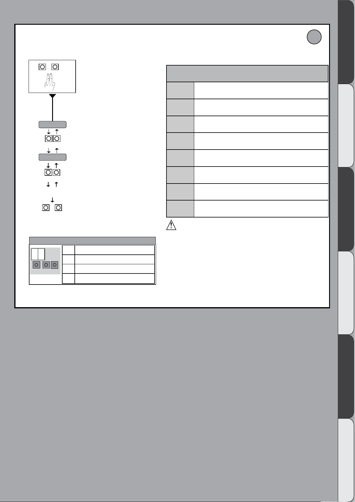
Diagnostics
code
01
02
03
04
05
06
07
08
09
10
14
15
Description Notes
Idle
Opening
Stop opening limit switch
Stop opening
Closing
Stop closing limit switch
Stop closing
Stop due to photocell triggering
Opening due to photocell triggering
Photocell triggering pause
Maximum working time in opening reached
Maximum working time in closing reached
PERSEO CBD 230.P SD - 13
Page 6

INSTALLER WARNINGS
WARNING! Important safety instructions. Carefully read and comply with
all the warnings and instructions that come with the product as incorrect
installation can cause injury to people and animals and damage to property.
The warnings and instructions give important information regarding safety,
installation, use and maintenance. Keep hold of instructions so that you can
attach them to the technical le and keep them handy for future reference.
GENERAL SAFETY
This product has been designed and built solely for the purpose indicated herein.
Uses other than those indicated herein might cause damage to the product and
create a hazard.
- The units making up the machine and its installation must meet the requirements
of the following European Directives, where applicable: 2004/108/EC, 2006/95/
EC, 2006/42/EC, 89/106/EC, 99/05/EC and later amendments. For all countries
outside the EEC, it is advisable to comply with the standards mentioned, in addition to any national standards in force, to achieve a good level of safety.
- The Manufacturer of this product (hereinafter referred to as the “Firm”) disclaims
all responsibility resulting from improper use or any use other than that for
which the product has been designed, as indicated herein, as well as for failure
to apply Good Practice in the construction of entry systems (doors, gates, etc.)
and for deformation that could occur during use.
- Before installing the product, make all structural changes required to produce
safety gaps and to provide protection from or isolate all crushing, shearing and
dragging hazard areas and danger zones in general in accordance with the
provisions of standards EN 12604 and 12453 or any local installation standards.
Check that the existing structure meets the necessary strength and stability
requirements.
- Before commencing installation, check the product for damage.
- The Firm is not responsible for failure to apply Good Practice in the construction
and maintenance of the doors, gates, etc. to be motorized, or for deformation
that might occur during use.
- Make sure the stated temperature range is compatible with the site in which the
automated system is due to be installed.
- Do not install this product in an explosive atmosphere: the presence of ammable
fumes or gas constitutes a serious safety hazard.
- Disconnect the electricity supply before performing any work on the system.
Also disconnect buer batteries, if any are connected.
- Before connecting the power supply, make sure the product ’s ratings match the
mains ratings and that a suitable residual current circuit breaker and overcurrent
protection device have been installed upline from the electrical system. Have
the automated system’s mains power supply tted with a switch or omnipolar
thermal-magnetic circuit breaker with a contact separation that meets code
requirements.
- Make sure that upline from the mains power supply there is a residual current
circuit breaker that trips at no more than 0.03A as well as any other equipment
required by code.
- Make sure the earth system has been installed correctly: earth all the metal parts
belonging to the entry system (doors, gates, etc.) and all parts of the system
featuring an earth terminal.
- Installation must be carried out using safety devices and controls that meet
standards EN 12978 and EN 12453.
- Impact forces can be reduced by using deformable edges.
- In the event impact forces exceed the values laid down by the relevant standards,
apply electro-sensitive or pressure-sensitive devices.
- Apply all safety devices (photocells, safety edges, etc.) required to keep the
area free of impact, crushing, dragging and shearing hazards. Bear in mind the
standards and directives in force, Good Practice criteria, intended use, the installation environment, the operating logic of the system and forces generated by
the automated system.
- Apply all signs required by current code to identify hazardous areas (residual
risks). All installations must be visibly identied in compliance with the provisions
of standard EN 13241-1.
- Once installation is complete, apply a nameplate featuring the door/gate’s data.
- This product cannot be installed on leaves incorporating doors (unless the motor
can be activated only when the door is closed).
- If the automated system is installed at a height of less than 2.5 m or is accessible,
the electrical and mechanical parts must be suitably protected.
- Install any xed controls in a position where they will not cause a hazard, away
from moving parts. More specically, hold-to-run controls must be positioned
within direct sight of the part being controlled and, unless they are key operated,
must be installed at a height of at least 1.5 m and in a place where they cannot
be reached by the public.
- Apply at least one warning light (ashing light) in a visible position, and also
attach a Warning sign to the structure.
- Attach a label near the operating device, in a permanent fashion, with information on how to operate the automated system’s manual release.
- Make sure that, during operation, mechanical risks are avoided or relevant
protective measures taken and, more specically, that nothing can be banged,
crushed, caught or cut between the part being operated and surrounding parts.
- Once installation is complete, make sure the motor automation settings are
correct and that the safety and release systems are working properly.
- Only use original spare parts for any maintenance or repair work. The Firm disclaims all responsibility for the correct operation and safety of the automated
system if parts from other manufacturers are used.
- Do not make any modications to the automated system’s components unless
explicitly authorized by the Firm.
- Instruct the system’s user on what residual risks may be encountered, on the
control systems that have been applied and on how to open the system manually in an emergency. give the user guide to the end user.
- Dispose of packaging materials (plastic, cardboard, polystyrene, etc.) in accordance with the provisions of the laws in force. Keep nylon bags and polystyrene
out of reach of children.
WIRING
WARNING! For connection to the mains power supply, use: a multicore cable with
a cross-sectional area of at least 5x1.5mm
phase power supplies or 3x1.5mm
type H05 VV-F cable can be used with a cross-sectional area of 4x1.5mm2). To connect auxiliary equipment, use wires with a cross-sectional area of at least 0.5 mm
- Only use pushbuttons with a capacity of 10A-250V or more.
- Wires must be secured with additional fastening near the terminals (for example,
using cable clamps) in order to keep live parts well separated from safety extra
low voltage parts.
- During installation, the power cable must be stripped to allow the earth wire
to be connected to the relevant terminal, while leaving the live wires as short
as possible. The earth wire must be the last to be pulled taut in the event the
cable’s fastening device comes loose.
WARNING! safety extra low voltage wires must be kept physically separate from
low voltage wires.
Only qualied personnel (professional installer) should be allowed to access
live parts.
CHECKING THE AUTOMATED SYSTEM AND MAINTENANCE
Before the automated system is nally put into operation, and during maintenance
work, perform the following checks meticulously:
- Make sure all components are fastened securely.
- Check starting and stopping operations in the case of manual control.
- Check the logic for normal or personalized operation.
- For sliding gates only: check that the rack and pinion mesh correctly with 2 mm
of play along the full length of the rack; keep the track the gate slides on clean
and free of debris at all times.
- For sliding gates and doors only: make sure the gate’s running track is straight
and horizontal and that the wheels are strong enough to take the weight of the
gate.
- For cantilever sliding gates only: make sure there is no dipping or swinging
during operation.
- For swing gates only: make sure the leaves’ axis of rotation is perfectly vertical.
- Check that all safety devices (photocells, safety edges, etc.) are working properly
and that the anti-crush safety device is set correctly, making sure that the force
of impact measured at the points provided for by standard EN 12445 is lower
than the value laid down by standard EN 12453.
- Impact forces can be reduced by using deformable edges.
- Make sure that the emergency operation works, where this feature is provided.
- Check opening and closing operations with the control devices applied.
- Check that electrical connections and cabling are intact, making extra sure that
insulating sheaths and cable glands are undamaged.
- While performing maintenance, clean the photocells’ optics.
- When the automated system is out of service for any length of time, activate the
emergency release (see “EMERGENCY OPERATION” section) so that the operated
part is made idle, thus allowing the gate to be opened and closed manually.
-
If the power cord is damaged, it must be replaced by the manufacturer or their
technical assistance department or other such qualied person to avoid any risk .
- If “D” type devices are installed (as dened by EN12453), connect in unveried
mode, foresee mandatory maintenance at least every six months
WARNING!
Remember that the drive is designed to make the gate/door easier to use and
will not solve problems as a result of defective or poorly performed installation
or lack of maintenance
SCRAPPING
Materials must be disposed of in accordance with the regulations in force. There
are no particular hazards or risks involved in scrapping the automated system. For
the purpose of recycling, it is best to separate dismantled parts into like materials
(electrical parts - copper - aluminium - plastic - etc.).
DISMANTLING
If the automated system is being dismantled in order to be reassembled at another
site, you are required to:
- Cut o the power and disconnect the whole electrical system.
- Remove the actuator from the base it is mounted on.
- Remove all the installation’s components.
- See to the replacement of any components that cannot be removed or happen
to be damaged.
2
or 4x1.5mm2 when dealing with three-
2
for single-phase supplies (by way of example,
Anything that is not explicitly provided for in the installation manual is not allowed. The operator’s proper operation can only be
guaranteed if the information given is complied with. The Firm shall
not be answerable for damage caused by failure to comply with the
instructions featured herein.
While we will not alter the product’s essential features, the Firm reserves the right, at any time, to make those changes deemed opportune to improve the product from a technical, design or commercial
point of view, and will not be required to update this publication
accordingly.
D811944_03
2
.
14 - PERSEO CBD 230.P SD
AVVERTENZE PER L’INSTALLATORE D811766_06
Page 7

INSTALLATION MANUAL
1) GENERAL INFORMATION
D811944_03
The PERSEO CBD 230.P SD control board comes with standard factory settings.
Any change must be made using the programmer with built-in display.
Its main features are:
Control of up to 4 bollards: STOPPY MBB -500 C. - STOPPY MBB 219-700 C.
Note: Bollards of the same type must be used.
- Separate inputs for safety devices
- Built-in radio receiver rolling code with transmitter cloning.
The board has a terminal strip of the removable kind to make maintenance or
replacement easier. It comes with a series of prewired jumpers to make the installer ’s
job on site easier. If the terminals are being used, remove the relevant jumpers.
2) TECHNICAL SPECIFICATIONS
Power supply* 220-230V 50-60Hz (*)
Motor outpu 220-230V~; 3A max
Flashing light/trac light 220-230V~; 40W
Accessory output: 24V~; 1A max
LED Output 24V~ 0,1A max
Buzzer Output 24V~ 0,1A max
Aux Contact Max 24V 0,5A
2nd Ch rx Contact Max 24V 0,5A
Low voltage/mains insulation >2Mohm 500Vdc
Operating temperature range -20° C+ 60° C
Thermal overload protection built into motor
Dielectric rigidity mains/LV 2500Vac for 1 second
Dimensions See Fig.B
Fuses See Fig.C
3) RECEIVER TECHNICAL SPECIFICATIONS
Max. n° of radio transmitters that
can be memorized
Frequency 433.92 MHz
2048
Code by means of Rolling-code algorithm
N° of combinations 4 billion
RADIO CHANNEL FUNCTIONALITY
PR1
PR 2
Select the command from parameter
R1
Closes the relay contact on the terminal
block J4 “2nd CH RX”
(* other voltages to order)
Usable transmitter versions:
All ROLLING CODE transmitters compatible with
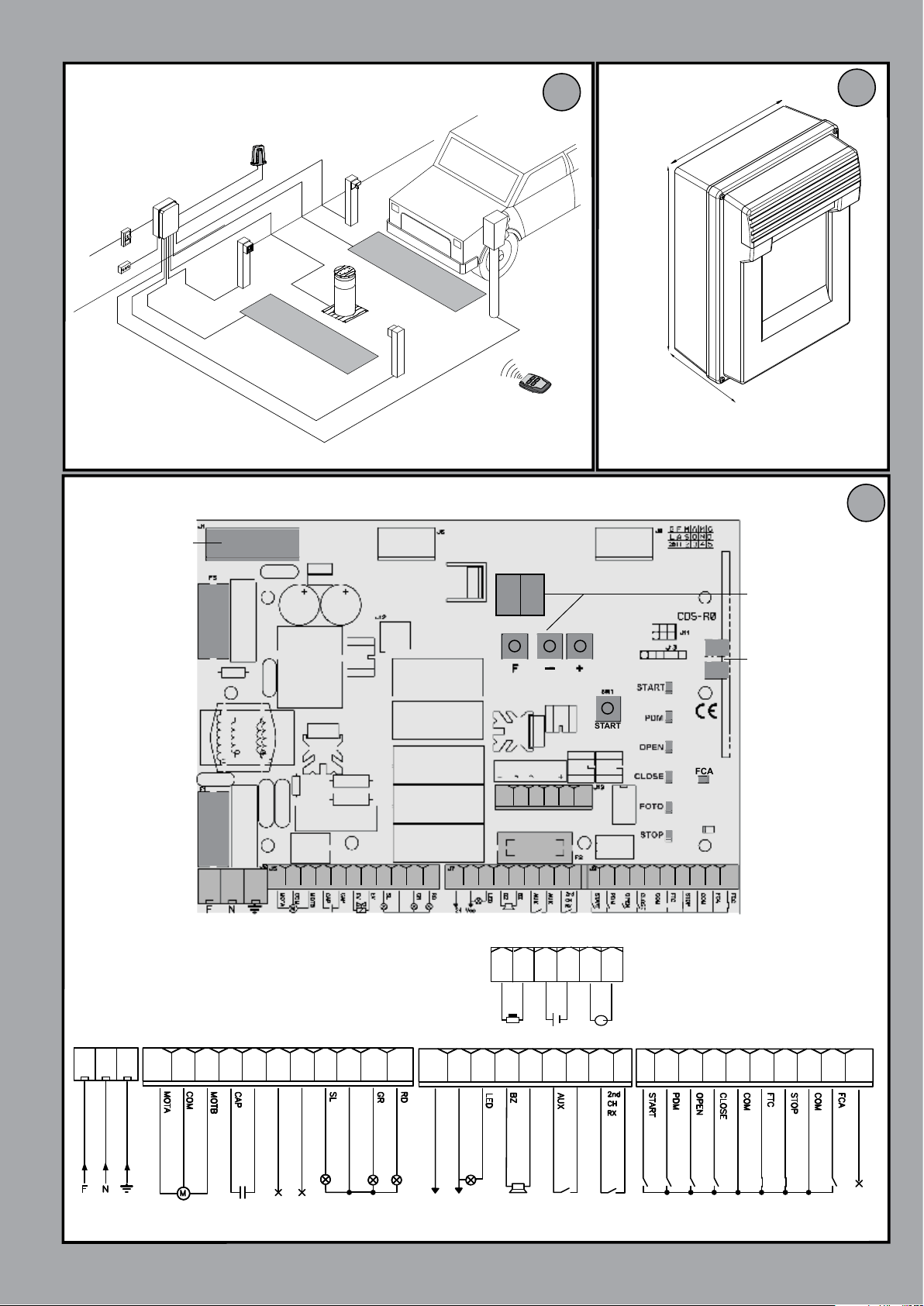
3) TUBE ARRANGEMENT Fig. A
4) CONTROL PANEL DIMENSIONS Fig.B
5) TERMINAL BOARD WIRING Fig. C
WARNINGS - When performing wiring and installation, refer to the standards in
force and, whatever the case, apply good practice principles.
Wires carrying dierent voltages must be kept physically separate from each other,
or they must be suitably insulated with at least 1mm of additional insulation.
Wires must be secured with additional fastening near the terminals, using devices
such as cable clamps.
All connecting cables must be kept far enough away from the dissipater.
WARNING! For connection to the mains power supply, use a multicore
cable with a cross-sectional area of at least 3x1.5mm2 of the kind provided
for by the regulations in force.
To connect the motors, use a cable with a cross-sectional area of at least 1.5mm2
of the kind provided for by the regulations in force. By way of example, if the
cable is run outside (unprotected), it must be at least type H07RN-F, while if it is
run inside (in a raceway), it must be at least type H05 VV-F.
ENGLISH
POWER TERMINAL BLOCK J2
Terminal Description
L N E
MO TA
M
COM
MOTB
CAP
CAP
EV
EV
SL
SL-COM GR-RD-COM
GR
RD
Single-phase power supply 220-230V 50/60Hz, with earth cable
L Live
N Neutral
E Earth
Motor connection
MOTA Motor opening
COM Motor Common
MOTB Motor closing
Motor capacitor
Not used
SL Flashing Light - max. 40W
SL-COM/ GR-RD-COM 230V
GR Green Light - max. 40W
RD Red Light - max. 40W
PERSEO CBD 230.P SD - 15
Page 8

POWER TERMINAL BLOCK J5
Terminal Description
24 Vac
INSTALLATION MANUAL
D811944_03
OUT24
Output 24V~, 1A MAX
24 Vac
BZ
AUX
2nd
CH
RX
INPUTS TERMINAL BLOCK J9
Terminal Description
START
PDM
OPEN
LED
BZ
AUX
COM
COM
COM
LED (Cover lights)
Self-powered output. 24V~, 100mA max
BZ (Cover buzzer)
Self-powered output. 24V, 100mA max
AUX
Free contact relay output; 500mA max, 24V / Vdc
2nd CH RX
Built-in radio receiver 2nd channel N.O. output, max. 500mA, 24 Vac/Vdc
START
N.O. input that operates the bollard’s opening and closing. The command is ignored while opening.
PDM
Programmable input. Use parameters FP, PD and AU for the setting procedure.
OPEN
N.O. input - opening only Connect clocks, daily timers or weekly timers here if wanted.
By keeping this input controlled, the automation performs the opening manoeuvre and will close automatically only
when the input is freed.
COM
CLOSE
FTC
COM
STOP
COM
FCA
COM
FCC
COM
INPUTS TERMINAL BLOCK J10.
Terminal Description
EF
+
BAT
SHIELD
ANT
CLOSE
N.O. input for closing. It allows the automation to be closed only if the safety devices have not triggered.
FTC
NC safety input (photocell). Enter the programme wanted by programming the FT parameter. It triggers only in the
closing phase; it never triggers in opening.
STOP
N.C. safety input. When it is activated, the automation is immediately stopped. During the pause time, a stop control
eliminates the automatic closing, leaving the bollard open waiting for a command.
FCA
Opening limit switch N.O. input. . When activated the opening travel nishes.
Not used
EF Electric brake output
Connection for two white power supply cables for the motor’s parking electric brake.
Activation is possible only when the bollard is completely lifted.
BAT Input for anti blackout electric brake feeder.
Permits the continuous power supply of the electric brake even without electrical energy, preventing the bollard
from lowering spontaneously in case of a blackout. Do not connect the batteries directly to this input but request
the original accessory STOPPY BAT.
ANTENNA
Antenna connection for the integrated receiver.
16 - PERSEO CBD 230.P SD
Page 9

INSTALLATION MANUAL
PR2 for CH2 output chanel
PR1
for CH1output chanel
2 blinks followed by a
pause of about 1 second.
1
1
6 blinks followed by a pause
of about 1 second.
NUMBER OF LED DL1 BLINKING SIGNALS
1
When pressing the key PR1 (for channel 1) or PR2 (for channel 2) for the first time, the receiver sets to the programming
mode. Every time the key PR1 is pressed after that, the receiver switches to the configuration for the subsequent function, that
is indicated by the number of flashings (see table).
For example, if PR2 is pressed for 4 consecutive times, the receiver stores the second channel as timer output
(4 flashings/pause/4 flashings/pause/...).
At this stage, after selecting the channel (PR1 or PR2) and the desired function, the key T (T1-T2-T3 or T4) of the transmitter
will be stored in the memory of the receiver as indicated in the table for programming.
Programming
and
Impulse output
Press the hidden key (Fig.4) on the transmitter until the
LED remains lit, then press the T key (1-2-3 or 4) on
the transmitter until it starts flashing again, wait for the
LED to go off or switch off the power. The transmitter's
T key is now memorized.
LEGEND
Constant blinking.
Automatic memory
storage only
with
impulse output
The key T1 of the transmitter is automatically stored on the output
CH1 while the key T2 on CH2. Do not store the TRC1 with this
function (key T2 is not available).
Press the hidden key (Fig.4) on the transmitter until the
LED remains lit, then press key T1 on the transmitter (if
other keys are pressed, they are ignored) until it starts
flashing again, wait for the LED to go off (10 sec) or
transmit a key to exit. T1 and T2 are now automatically
memorized on CH1 and CH2.
Standard Programming
Advanced Programming
Cancellation of
the entire
receiver memory
WARNING! This operation deletes all of the radiocontrols stored
on channel 1 and channel 2 from the memory of the receiver.
While the LED is flashing, keep buttons PR1 and PR2
on the receiver held down together for longer than 10
sec. The LED flashes very quickly.
By the time the LED goes off, all the transmitters are
deleted and you exit programming mode.
FUNCTION
FUNCTION DESCRIPTION
PROGRAMMING PROCEDURE
The associated output relay stays attracted for 1 second.
You will exit programming mode if no memorizing is performed
for 10 seconds.
X4
WIRELESS PROGRAMMING
6) SELECT BOLLARD FIG.D
D811944_03
Set the type of motor connected to the board
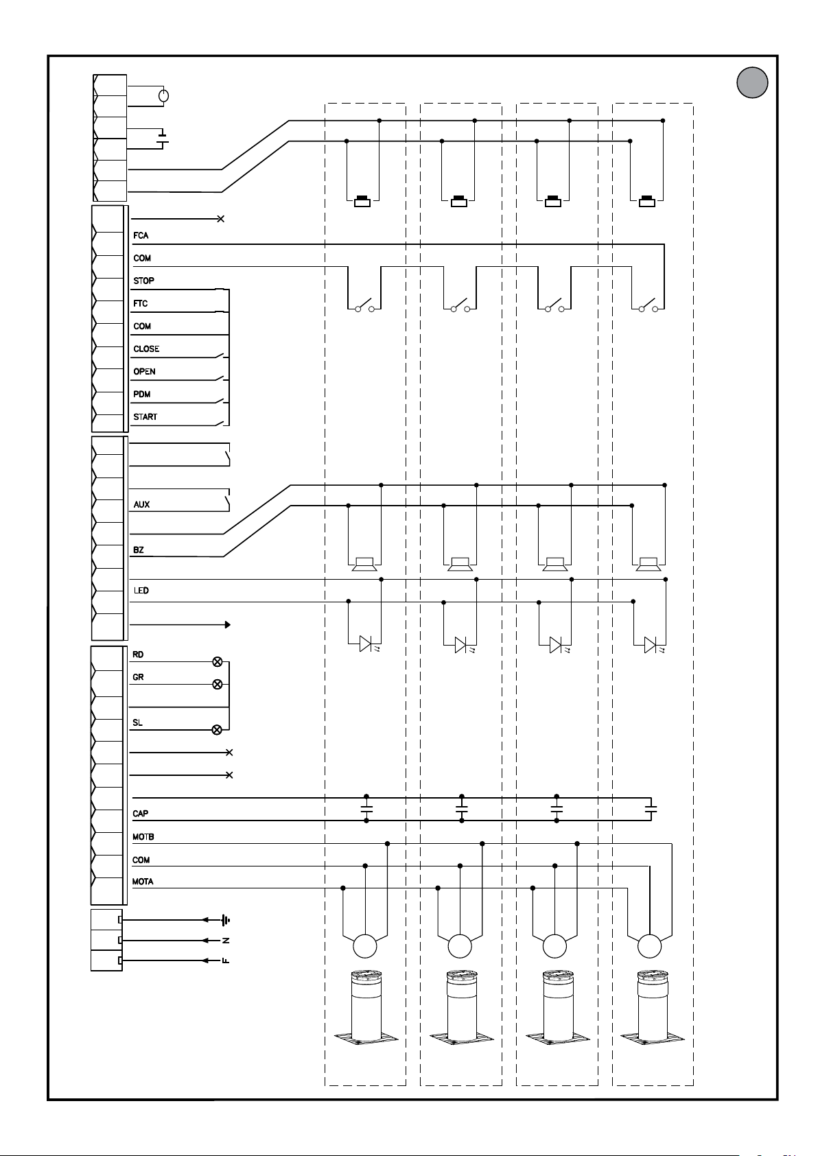
7) CONNECTIONS FOR SIMULTANEOUS OPERATION FIG.E
The PERSEO CBD 230.P SD control unit can be used to operate up to four
bollards connected in parallel, thus achieving simultaneous operation with a
single control panel.
Use a junction box with a suitable protection rating to wire the bollards together
so as to avoid bulky connections near the control panel.
MOTOR CABLES: Connect in parallel, observing the motors’ polarity by joining
together the black cables, brown cables and blue cables.
CAPACITOR CABLES: Connect in parallel in the terminals provided
ELECTRONIC BRAKE CABLES: Connect in parallel in the terminals provided
LIGHT CABLES: Connect in parallel in the terminals provided
OPENING LIMIT SWITCH CABLES: Connect in series in the terminals provided
BUZZER CABLES: Connect in parallel in the terminals provided
8)CALLING UP MENUS : FIG.1
8.1) LEVEL 1 PROGRAMMING MENU (TABLE “A”)
8.2) LEVEL 2 PROGRAMMING MENU (TABLE “B”)
8.3) LEVEL 3 PROGRAMMING MENU (TABLE “C”)
9) TROUBLESHOOTING
If you encounter a malfunction of any kind, make sure that you have selected
the correct bollard (FIG.D).
- Lights on top cap double ashing. Indicates scheduled maintenance is due.
Check Sr, Nt and NL parameters
- Lights on top cap triple ashing and status 14 or 15 on display at end of
operation. Check the opening limit switch
10) WIRELESS PROGRAMMING
10.1) MANUAL PROGRAMMING
In the case of standard installations where no advanced functions are required,
it is possible to proceed to manual storage of the transmitters, making referen-
ce to programming table A and to the example for basic programming.
1) If you wish the transmitter to activate output 1, press pushbutton PR1, otherwise if you wish the transmitter to activate output 2, press pushbutton PR2.
2) When LED DL1 starts blinking, press hidden key on the transmitter, LED DL1
will remain continuously lit.
3) Press the key of the transmitter to be memorized, LED DL1 will ash quickly
to indicate that it has been memorized successfully. Flashing as normal will then
be resumed.
4) To memorize another transmitter, repeat steps 2) and 3).
5) To exit memorizing mode, wait for the LED to go o completely or press the
key of a remote control that has just been memorized.
IMPORTANT NOTE: ATTACH THE ADHESIVE KEY LABEL TO THE FIRST MEMORISED TRANSMITTER (MASTER).
In the case of manual programming, the rst transmitter assigns the key code
to the receiver; this code is necessary in order to carry out subsequent cloning
of the radio transmitters.
10.2) SELF-LEARNING MODE PROGRAMMING
This mode is used to copy the keys of a transmitter already stored in the receiver
memory, without accessing the receiver.
The rst transmitter is to be memorised in manual mode (see paragraph 8.4).
a) Press hidden key on the transmitter already memorised.
b) Press key T on the transmitter already memorised, which is also to be attributed
to the new transmitter.
c) Within 10 s., press hidden key on the new transmitter to be memorised.
d) Press key T to be attributed to the new transmitter.
e) To memorise another transmitter, repeat the procedure from step (c) within a
maximum time of 10 seconds, otherwise the receiver exits the programming mode.
f ) To copy another key, repeat from step (a), having waited for the receiver to exit the
programming mode (or after disconnecting the receiver from the power supply).
ENGLISH
PERSEO CBD 230.P SD - 17
Page 10

INSTALLATION MANUAL
TABLE “A” - LEVEL 1° PROGRAMMING
Parameter Denition Default
Selects the
Lo
CL
Ft
OB
PF
LD
Bu
functioning
logic.
Close input
conguration
Photocells 02
Not available
Warning ash 00
Bollard lights 00
Buzzer 01
01
00
03
Cross Out
Setting Used
00
01
02
00
01
02
00
01
02
00
01
02
03
0-30
00
01
02
03
00
01
Optional Extras Description
Hold-to-run
Semi automatic
Automatic
Standard close input The command causes the device to close
Close-when-released input
The close command acts as a release closing and safety
function.
During closure, it reopens and waits for the photoelectric
cell free commands.
When closing it reopens; reclosing after 1’’ when the photocell is disengaged
When closing it reopens; reclosing after 5’’ when the photocell is disengaged
Not available
Cover lights ashing during movement, cover lights xed
when the bollard is opened and closed
Cover lights ashing during movement and with bollard
closed, cover lights xed when the bollard is open
Cover lights always ashing
Cover lights ashing during movement and with bollard
open, cover lights xed when the bollard is closed
Buzzer o
Buzzer on during movement
The automation works when the commands are held
down. The start command opens once and closes once.
The automation works with jog commands, without
automatic reclosing. Hence, when fully open, to control
closing you need to act on the start or close command
respectively.
The automation works in jogs.When the opening
manoeuvre is completed in the standard cycle, automatic reclosing is activated after the pause time set
(parameter tP).
Close-when-released input
This mode has been developed so the bollard closes
automatically only when the vehicle has completely
passed by the photocell or magnetic detector (the
most suitable accessories for this purpose). Connect
the NO contact of the detector or photocell to the
Close contact terminals.
If the vehicle is on the detector or in front of the photocell it does not cause immediate closing but rather you
have to wait for the signal to be released.
The close command acts as a release closing and safety
function.
When closing, the close command engaging stops the
automation. When disengaged the bollard resumes
closing.
Before each start, the ashing light is activated, for the
set time, along with the AUX output, if set (AU parameter). A 0 pre-ashing is disabled.
D811944_03
Resetting
dF
tP
default parameters.
Pause time
(expressed in
seconds)
18 - PERSEO CBD 230.P SD
00
01
02
00
03
04
05
10
1-99
No resetting
Resetting the default parameters.
To reset the default parameters, set parameter dF on 1
and exit the menu’.
Not available
Waiting time before automatic closing in Automatic
mode (Lo parameter).
Page 11

TABLE “B” - LEVEL 2° PROGRAMMING
D811944_03
INSTALLATION MANUAL
Parameter Denition Default
Sr
Nt
NL
AV
Te
Cr
Request for
maintenance
Programming
maintenance
cycles in
thousands
Programming
maintenance
cycles in
millions
AUX
TERMON 00
Slow-down
speed
00
00
0.0
00
20
Cross Out
Setting Used
00
01
02
00-99
0.0-9.9
00
01
02
03
04
05
06
07
08
09
10
11
00-30
10-45
Optional Extras Description
disabled the request for maintenance is not active.
active on the congured outputs
active on the congured outputs and the bollard lights ash
twice
scheduled maintenance required
photocell triggering
$ non disponibile
PDM contact actuated The AUX output is activated if the PDM input is closed.
bollard closed The AUX output is activated when the bollard is closed.
bollard open The AUX output is activated when the bollard is open.
stop contact actuated The AUX output is activated if the Stop input is open.
warning ash
start contact The AUX output is activated if the Start input is closed.
open contact The AUX output is activated if the Open input is closed.
blackout
assistance required
at the end of the countdown, by means of counters nt
and nL, one of the programmed outputs is activated
(see parameter Av)
at the end of the countdown, by means of counters nt
and nL, one of the programmed outputs is activated
(see parameter Av) and the bollard lights ash twice.
Thanks to the combination of the two parameters
the countdown can be set after which a request for
maintenance is signalled.
Thousands can be set with the nt parameter, millions
with the nL parameter. Example: to set 275,000 maintenance manoeuvres set nL on 0.2 and nt on 75. The
value displayed in the parameters updates along with
the manoeuvres.
If the maintenance request is enabled (Sr parameter),
the AUX output is activated once the value set for
parameter nt and nl is reached.
The AUX output is activated if the photocell input is
open, photocell triggered.
The AUX output is activated as described in the Pf
pre-ashing parameter.
The AUX output is activated when the device is
switched on
If congured, the contact indicates that the electronic
control unit has detected an error in the automated device and, more specically, has detected that the limit
switches are broken. Whatever the case, the lights on
the top cap triple ash to report the error.
Sets the temperature dierence between the bollard’s
motor and the ambient temperature in centigrade
degrees.
If the parameter is not zero, the control unit will heat
the motor in order to obtain the set temperature
dierence.
Example: TE=15. The control unit will ensure that the
motor maintains a temperature that is 15° above the
ambient temperature.
By setting the parameter FP=3, it is possible to enable
or disable the Termon system, operating directly on the
PDM input.
Sets the deceleration speed at the end of the closing
manoeuvre.
The value of the deceleration speed at the end of
opening is preset by the company.
ENGLISH
PERSEO CBD 230.P SD - 19
Page 12

TABLE “C” - LEVEL 3° PROGRAMMING
Parameter Denition Default
Cross Out
Setting Used
D811944_03
Optional Extras Description
PD
Pa
CP
FP
R1
HT
PDM dynamic
input polarity
Output AUX
polarity
Commands
during pause
Special PDM
functions
Radio channel 1
command
selection
Select mains
frequency
00
00
01
00
00
01
00
01
01
00
01
00
02
03
00
01
01
02
30
20-80
Input congured as NO
Input congured as NC
Output congured as NO
Output congured as NC
OFF
ON
None Not congured.
Opening consent
Opening consent and pause time reset
TERMON enabling
Channel 1 deactivated
Channel 1 set as START
Channel 1 set as OPEN
The outputs can be congured as NO or NC, but in
the event of a power outage, the contacts will open
anyway
Depending on how the parameter is set, the automated device accepts or rejects commands during pause
time..
PDM is used to enable opening. Until it is pressed, no
opening command is accepted through the OPEN
input. If PDM is held down, no closing command is
accepted through the CLOSE input, meaning the
bollard stays open.
The PDM functions as described in point 1, but in case
of automatic logic, the pause time is reloaded.
The PDM function enables the TERMON system. Based
on the setting of the PD parameter, the closing or
opening of the contact activates or deactivates the
TERMON system. This makes it possible to interface a
schedule with a potential free contact to optimise the
heating system.
20 - PERSEO CBD 230.P SD
 Loading...