

Page 1
CONTROL UNIT
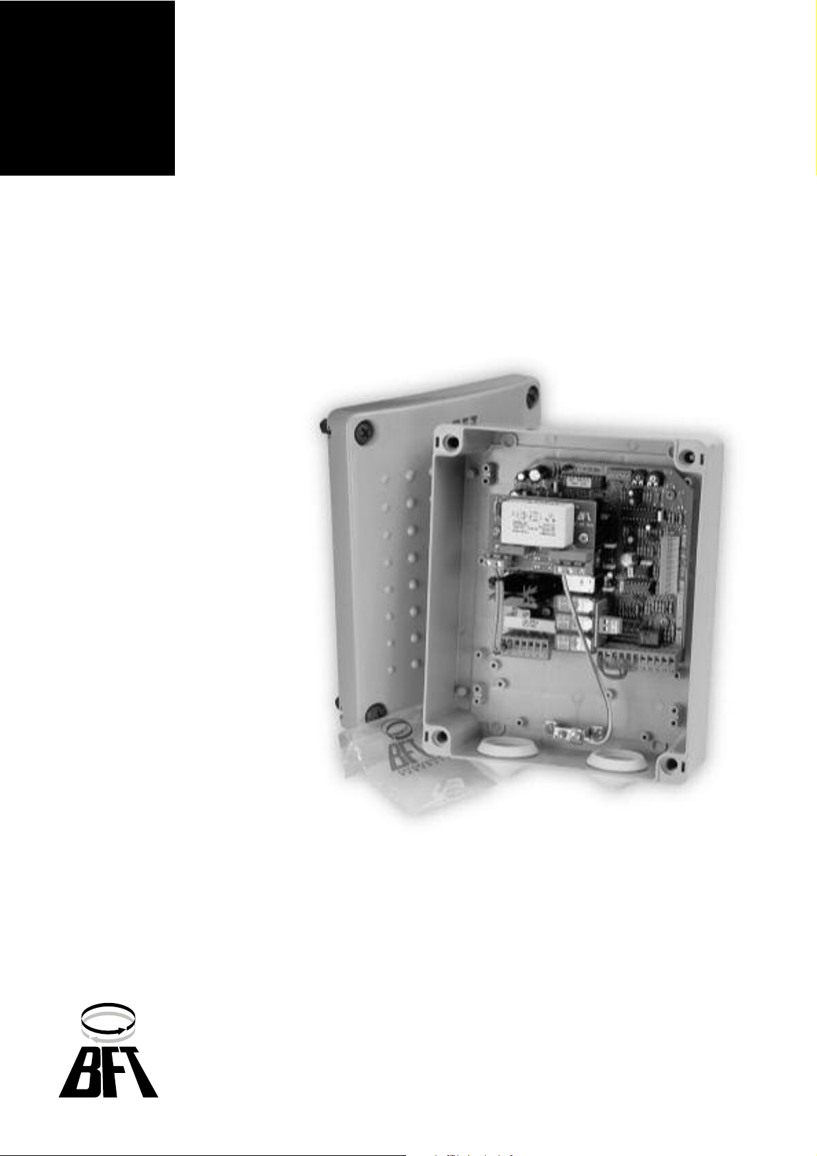
ORION G
D811230
30-11-00 Vers. 04
Page 2

447
D811230_04
ORION G-GBR
ORION G-GBR
Thank you for buying this product, our company is sure that you will be more
than satisfied with the product’s performance. The product is supplied with
a “WARNINGS” leaflet and an “INSTRUCTION MANUAL”. These should
both be read carefully as they provide important information about safety,
installation, operation and maintenance. This product complies with the
recognised technical standards and safety regulations. We declare that this
product is in conformity with the following European Directives: 89/336/
EEC and subsequent amendments.
1) GENERAL OUTLINE
The ORION G board is used to control one single-phase motor of up to 800W.
Its main feature is the electronic breaking control during the stopping phase.
ATTENTION - Only qualified personnel should be employed.
2) GENERAL SAFETY
WARNING! An incorrect installation or improper use of the product
can cause damage to persons, animals or things.
• The “Warnings” leaflet and “Instruction booklet” supplied with this
product should be read carefully as they provide important information
about safety, installation, use and maintenance.
• Scrap packing materials (plastic, cardboard, polystyrene etc) according
to the provisions set out by current standards. Keep nylon or polystyrene
bags out of children’s reach.
• Keep the instructions together with the technical brochure for future
reference.
• This product was exclusively designed and manufactured for the use
specified in the present documentation. Any other use not specified in
this documentation could damage the product and be dangerous.
• The Company declines all responsibility for any consequences resulting
from improper use of the product, or use which is different from that
expected and specified in the present documentation.
• Do not install the product in explosive atmosphere.
• The Company declines all responsibility for any consequences resulting
from failure to observe Good Technical Practice when constructing
closing structures (door, gates etc.), as well as from any deformation
which might occur during use.
• The installation must comply with the provisions set out by the following
European Directives: 89/336/EEC and subsequent amendments.
• Disconnect the electrical power supply before carrying out any work on
the installation. Also disconnect any buffer batteries, if fitted.
• Fit an omnipolar or magnetothermal switch on the mains power supply,
having a contact opening distance equal to or greater than 3mm.
• Check that a differential switch with a 0.03A threshold is fitted just
before the power supply mains.
• Check that earthing is carried out correctly: connect all metal parts for
closure (doors, gates etc.) and all system components provided with an
earth terminal.
• The Company declines all responsibility with respect to the automation
safety and correct operation when other manufacturers’ components
are used.
• Only use original parts for any maintenance or repair operation.
• Do not modify the automation components, unless explicitly authorised
by the company.
• Instruct the product user about the control systems provided and the
manual opening operation in case of emergency.
• Do not allow persons or ch ildren to rem ain in the automation
ope ration area.
• Keep radio control or other control devices out of children’s reach, in
order to avoid unintentional automation activation.
• The user must avoid any attempt to carry out work or repair on the
automation system, and always request the assistance of qualified
personnel.
• Anything which is not expressly provided for in the present instructions,
is not allowed.
3) TECHNICAL SPECIFICATIONS
Power supply: ....................................................... 230Vac ±10% 50/60Hz
Max. motor power: .............................................................................800W
Power supply to accessories: ................................... 24Vac - 180mA max
Panel consumption: ....................................................................... 100 mA
Fixed operation time: ............................................................ 140 s approx.
Fixed pedestrian operation time: .............................................. 9 s approx.
Adjustable automatic closing time: ...................................... from 2 to 90 s
Pre-alarm time: ...................................................................................... 3 s
Environmental conditions: ........................................ from -20°C to +55°C
Protection degree: ............................................................................ IP 55
Dimensions: ................................................................................. see fig.1
Weight: ............................................................................................. 1.2 kg
4) TERMINAL BOARD CONNECTIONS (Fig.2)
ATTENTION! - Keep the low voltage connections definitely separated from
the power supply connections.
JP3 FILTER
1 Earth (GND).
2-3 Single-phase power supply: 230V ± 10% 50/60 Hz. (2 Neutral - 3
Phase).
ORION G
3-4-5 Motor connection (3/5 operation - 4 common wire).
3-6 Capacitor.
2-7 Blinker 230 Vac.
8-9 Open-Close push button and key selector (N.O.).
8-10 Stop push button (N.C.). If not used, leave jumped.
8-11 Photocell contact or rubber skirt(N.C.) If not used, leave jumped.
8-12 Opening limit switch (N.C.). If not used, leave jumped.
8-13 Closing limit switch (N.C.). If not used, leave jumped.
14-15 Output 24 Vac 180mA max.
15-16 Gate-open warning light 24 Vac 3W max.
17-18 Antenna input for radio receiver board (17 signal - 18 braid).
ATTENTION - To invert motor running direction, invert the motor connections
3 and 5 and the limit switch connections 12 and 13.
Do not move the capacitor connection.
SOG OPTIONAL BOARD (fig.2).
9-20 Opening push button (N.O.). When the “Open” command is given,
the motor opens independently of its state.
19-21 Closing push button (N.O.). When the “Close” command is given, the
motor closes independently of its state.
ATTENTION: In some versions of the ORION G boards, terminals 20
and 21 of the SOG optional board have the HOLD-TO-RUN control
feature (UP) instead of the separate open-close control (ACS).
19-22 Push button for pedestrian access (N.O.). When the “Pedestrian”
command is given, the gate opens of about 1 metre.
23-24 Rubber skirt contact connection (N.C.). If the rubber skirt steps in,
the movement is reversed for about 30 centimetres. If not used, leave
jumped.
25-26 Second radio channel output (if a twin-channel board is fitted).
5) DIP SWITCH FUNCTIONS (Fig.3)
DIP 1 MODE
OFF: A start impulse during the motor run causes the gate to stop (4 - step
operation) both in opening and closing phase.
ON: A start impulse during the motor run causes the gate to reverse
direction (2-step operation) in closing phase.
DIP 2 PRE-ALARM
OFF: The flashing light turns on simultaneously with the start of the motors.
ON: The flashing light turns on abt. 3 seconds before the motors start.
DIP 3 PHOTOCELLS
OFF: Photocell intervention causes the operator to stop both in the opening
or closing phase. After removing the obstacle, the operator opens.
ON: Photocell intervention has no effect on the opening phase and
immediately reverses movement during the closing phase.
DIP 4 AUTOMATIC CLOSING TIME TCA
OFF: Switches off the automatic closure
ON: The gate closes again automatically after a pause time set on the
trimmer T1. Such a function is activated:
- In full open position.
- In the opening phase by means of the start push button or radio control.
DIP 5 IMPULSE BLOCK
OFF: A start impulse during the opening phase causes the operator to stop.
ON: A start impulse during the opening phase has no effect.
DIP 6: Not used.
6) TRIMMER FUNCTIONS (Fig.3)
TRIMMER T1 TCA: Sets the pause time before the automatic closure. The
time can be increased by turning it clockwise.
CONTROL UNITS
CONTROL UNITS
Page 3

448
D811230_04
TRIMMER T2 BRAKE: Controls the braking couple.
ATTENTION - The trimmer braking effect is set by the manufacturer during
testing and is then sealed. If the trimmer needs recalibrating, please take
note of the following:
a) Braking should not be sudden.
b) Braking which is too weak creates slippage due to inertia.
Braking can be increased by turning it clockwise.
7) LED FUNCTIONS (Fig.1)
7.1) BOARD ORION G
1 - START
Lights up upon start impulse.
2 - STOP
Turns off upon opening of the block contact.
3 - PHOTOCELL
Turns off if photoelectric cells are not aligned or if there are obstacles
interfering with the cells.
4 - OPENING LIMIT SWITCH
Turns off in a full open position.
5 - CLOSING LIMIT SWITCH
Turns off in a full closed position.
6 - OPENS
Turns on during the motor opening phase.
7 - CLOSES
Turns on during the motor closing phase.
8 - MAINS SUPPLY
Turns on when there is power and when the fuses are integral.
SOG optional board
9 - OPENS
Turns on at the “hold-to-run” open command.
10 - CLOSES
Turns on at the “ hold-to-run” close command.
11 - RUBBER SKIRT ALARM
Turns on when the rubber or infrared safety skirts is activated.
12 - PEDESTRIAN
Turns on at the pedestrian opening command.
8) MAINTENANCE AND DEMOLITION
The maintenance of the system should only be carried out by qualified
personnel regularly. The materials making up the set and its packing must
be disposed of according to the regulations in force. Batteries must be
properly disposed of.
The descriptions and illustrations contained in the present manual
are not binding. The Company reserves the right to make any alterations
deemed appropriate for the technical, manufacturing and commercial
improvement of the product, while leaving the essential product
features unchanged, at any time and without undertaking to update
the present publication.
ORION G-GBR
ORION G-GBR
CONTROL UNITS
CONTROL UNITS
Page 4

449
D811230_04
Fig. 1
Fig. 3
Fig. 2
125
06
225
183
90
195
230V 50/60Hz 10%
+
-
JP3
JP2
JP1
1
1
2
3
4
M
5
6
7
8
9
10
11
12
13
14
15
16
17
18
19
20
21
22
23
24
25
26
2
3
Start
Bl.
Phot.
Swo.
Swc.
Open
Close
Ped
All CST
II° CAN
24V AC
OV
CA
ANTENNA
ANTENNE
ANTENNA
ANTENA
ANTENNE
ANTENNA
N
L
FILTRO - FILTER - FILTRE
FILTER - FILTRO - FLTRO
NO
NO
NC
NC
NC
NC
NO
NO
NC
160mA/T
10A/F
8
ON
DIP
T1 T2
1
1
83 4 5 6 7 9 10 11 12 13 14 15 16 17 18
22334 5 6
1
34444 3
2
JP3JP1
JP2
7
1 2 3 4
5
6
SOG
N
L
12
19 20 21 22 23 24 25 26
11 10 9
19
20
21
22
23
24
25 26
SOG
1) TRIMMER SIGILLATO
TRIMMER SCALED
TRIMMER SIGILLÈ
TRIMMER VERSLEGELT
TRIMMER SELLADO
TRIMMER LACRADO
2) INSERIMENTO SCHEDA RADIO RIC.
ENCLENCHEMENT CARTE RADIOREC.
PLUGGING-IN OF RADIO-RECEIVER BOARD
CONEXION TARJETA RADIORRECEPTOR
EINFÜGUNG KARTE FUNKEMPÄNGER
INSERÇÃO PLACA RÁDIO RECEPTOR
3) SCHEDE OPTIONAL
OPTIONAL BOARDS
OPTIONAL-KARTEN
FICHA OPCIONAL
CARTES OPTIONNELLES
PLACAS OPCIONAIS
4) MORSETTIERE PER IL COLLEGAMENTO
PLAQUE A BORNES POUR LA CONNECTION
TERMINAL BOARD FOR CONNECTION
CONECTORES PARA LA CONEXION
KLEMBRETT FÜR DEN ANSCHLUSS
RÉGUAS DE BORNES PARA CONEXÃO
ORION G-GBR
ORION G-GBR
CONTROL UNITS
CONTROL UNITS
 Loading...