

Page 1

OBERON
Limit Switch Adjustment
& Control Board Settings
Please remember these instruction are only a substitude and the full
Instruction manuals should always be read prior to the install
Page 2

www.bft.it
Control Board Setting
To simplify the setting of the limits switches, It’s recommend you remove the
big blue cover off the motor ( See Fig 2 below )
Firstly set the control board into ENGLISH ( ENG ) in the Language menu.
Also in the logic menu the “HOLD —TO — RUN” may be switched on from the
factory ( setting no 1 ) you need to switch this off ( setting 0 )
At this stage I would also program all your remotes in, under the RADIO menu
Page 3
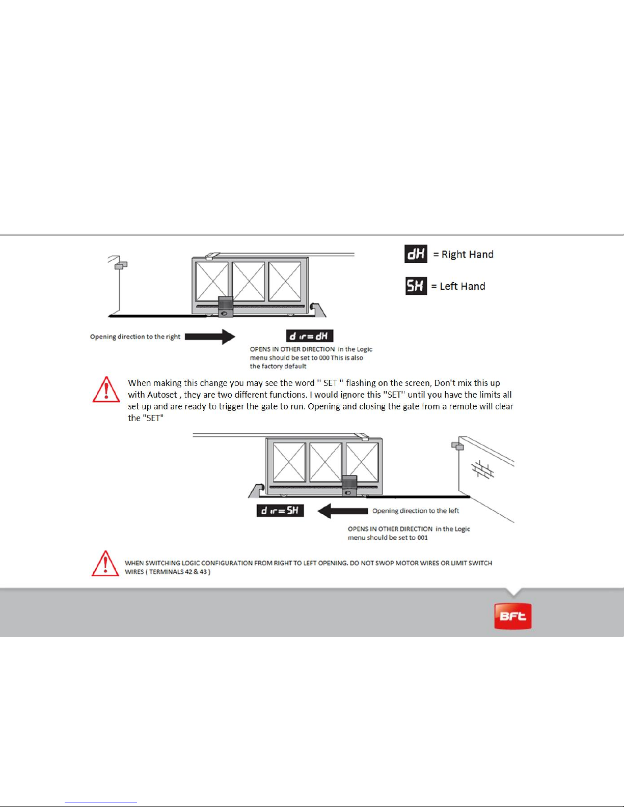
Setting the Motor Direction
Page 4

Limit Switch Adjustment
1.
Unlock the gate and manually open it to the
desired open position.
2.
3.
4.
During this manoeuvre look at which direction the
cams turn.
You will notice that the cams turn in a clockwise
direction, for a gate opening to the right and in an
anti-clockwise direction for a gate opening to the left.
This means for right hand opening gate the top Cam,
Cam A is the opening limit and then the bottom Cam,
Cam B is for closing.
5
. BUT for a left hand opening gate
gaste it will be the opposite. The top
Ca Cam, Cam A is now for closing
and bottom Cam, Cam B is for
the opening
Page 5

Limit switch adjustment
6.
By now you should have
1) Set your motor direction and identified which cam is for your opening and which one
is your closing
7.
Page 6

Limite switch adjustment
8.
9.
10
Now loosen the central screw ( lose enough to turn the
cams ) but not to lose
And manually move the gate to your desired open
position ( make sure you leaving a gap between the gate
and post ) Then turn your limit cam by hand until you
hear the click of the micro switch.
Now move your gate to the desired closed position, once
again making sure its not closed up against a post .
Manually turn the opposite limit cam by hand until you
hear the click
Now tighten the center screw
Page 7

Limite switch adjustment
11.
Manually move the gate off its limit switch, and lock the gearbox back in. Now
give the gate a start command from a remote or by a short across terminals 60
and 61. The gate will now move at a slow speed until it reaches the opening
limit switch.
With additional cycles you can do the fine adjustment
in open and close
12.
13.
Now by using the micrometer screw, adjust the exact limit
switch position. Be careful as these screws are quite
sensitive and a very small turn creates a big movement on
the gate
Page 8

Limit Switch Adjustment
14.
At this point you can run an autoset.
15.
16.
Important NOTE: adjust the parameters “slowdown distance“ in the opening
and closing, to ensure that the engine arrives in proximity of the limit switch
after at least 20-30 cm of slow speed, otherwise the stop ramp in to the limit
switch position is not precise.
For security reasons we recommend placing the gate to 100 mm before the
closed position and approximately 150 mm before fully opening position.
Page 9

© 2010, Bft Spa – All rights reserved.
This document is protected by copyright. No part of it may be modified, reproduced or distributed
in any form by any means without prior written authorization of Bft Spa..
THANK YOU
 Loading...