How it Works
Log In / Sign Up
Buy Points
How it Works
FAQ
Contact Us
Questions and Suggestions
Users
Bertazzoni
Loading...
K
K48HERTX + KC48HERTAV
K48HERTX + KC48HERTX
K48HERX14
2
K71A.HB4X
K71AMLF1XE.UA
K90 AM H CR A
2
K90 AM H NE A
2
K90 AM H VI A
2
K90 AM HX A
2
K90CONXA
K90 HER CR A
K90 HER NE A
K90 HER VI A
KC36HERNE
5
KC36HERTX
2
KC36HERVI
3
KC48HERTAV
2
KC48HERTX
KC48HERVI
5
KCH24XV
5
KCH30XV
5
KCH36XV
3
KG120CONX
KG120CONXA
KG30CONX
5
KG30X
3
KG36CONX
8
KG36X
2
KG48CONX
8
KG48X
3
KG90CONX
2
KG90CONXA
KIN 30 PER X
KIN 30 PRO X
7
KIN 36 PER X
KIN36PROX
6
KIN46PROX
4
kin48xt
KIN52MOD1XC
2
KIN70MOD1XB
KIN86MOD1XB
KMC30BI
4
KMC30NE
4
KMC30X
5
KMC36BI
4
KMC36NE
4
KMC36X
5
KMC48BI
5
KMC48NE
4
KMC48X
4
KO30PROX
5
KOTR30MXE
5
KOTR30X
7
KOTR30XT
7
KR110HER1ADC
KR70HER1ADA
KR70HER1NDA
3
KT120PRO1XA
KT60MAS1XB
KT60PRO1XA
KT90MAS1NEC
KT90MAS1XB
KT90PRO1XA
KTE60MOD1B
KTE60MOD1C
KTI120PRO1XA
KTI36XT
KTI42XT
KTI48XT
KTI90PRO1XA
KTV24PRO1X
6
KTV24XV
5
KTV30PRO1X
2
KTV30XV
5
KU100 PRO 1 X A
2
KU120 PRO 1 X A
2
KU122 PRO 1X
KU24 PRO 1X
KU24PRO1X14
7
KU24PRO1XV
5
KU30 PRO
KU30PRO1X
6
KU30PRO1X14
8
KU30PRO1XV
6
KU36PRO1X
6
KU36PRO1X14
7
KU36PRO1XV
6
KU36 PRO 2X
2
KU36PRO2X14
6
KU48PRO1X
3
KU48PRO1X14
5
KU48 PRO 2X
2
KU48PRO2X14
6
KU60 PRO 1X
KU90 PRO 1X
KU90 PRO 1 X A
2
KU90PRO2XA
KUD40PRO1XA
M
M3W0GTU4X5A
M3Y0GTU4X2A
Loading...
Loading...
Nothing found
KO30PROX
Installation Guide
1 pgs
79.33 Kb
0
Installation Manual
16 pgs
923.03 Kb
0
Installation Manual
1 pgs
115.62 Kb
0
Owner's Manual
40 pgs
1.95 Mb
0
Specifications
2 pgs
241.29 Kb
0
Table of contents
Loading...
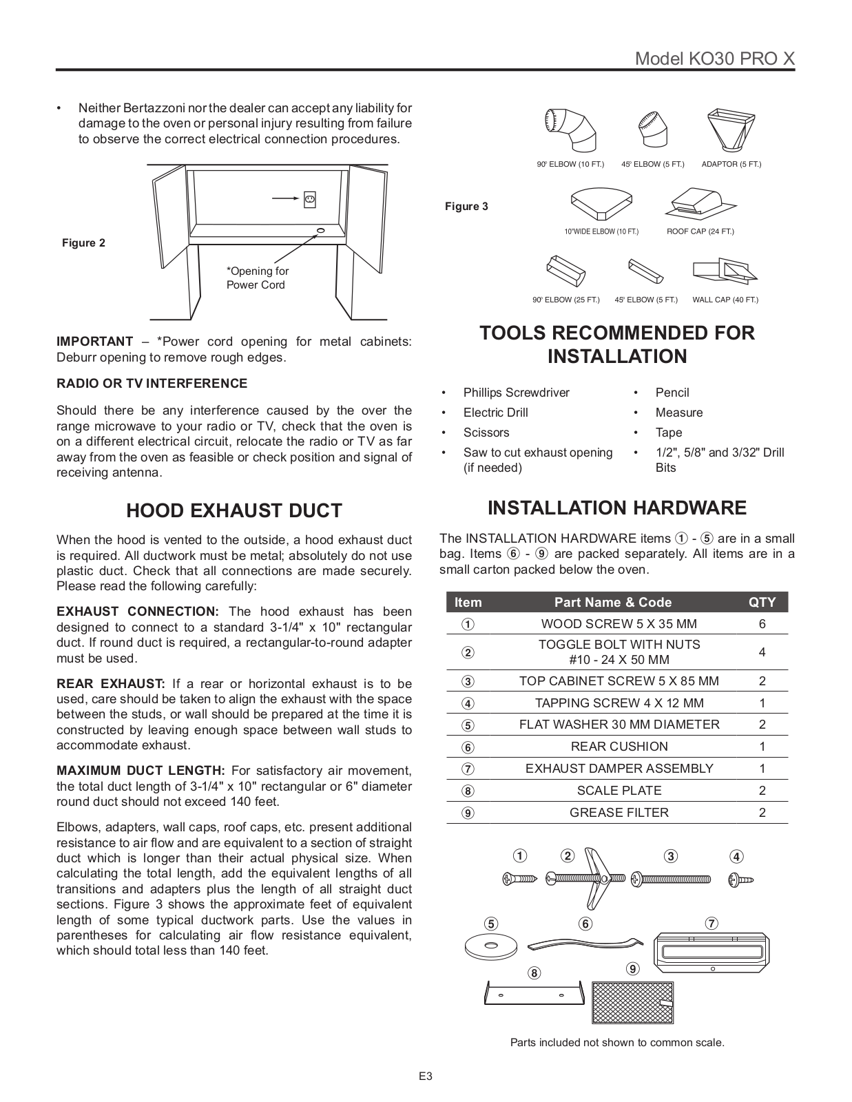
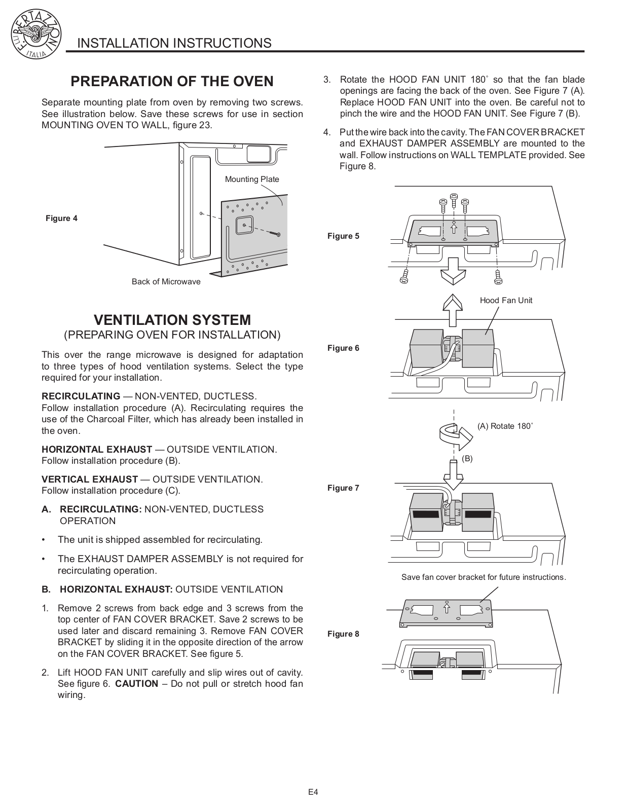
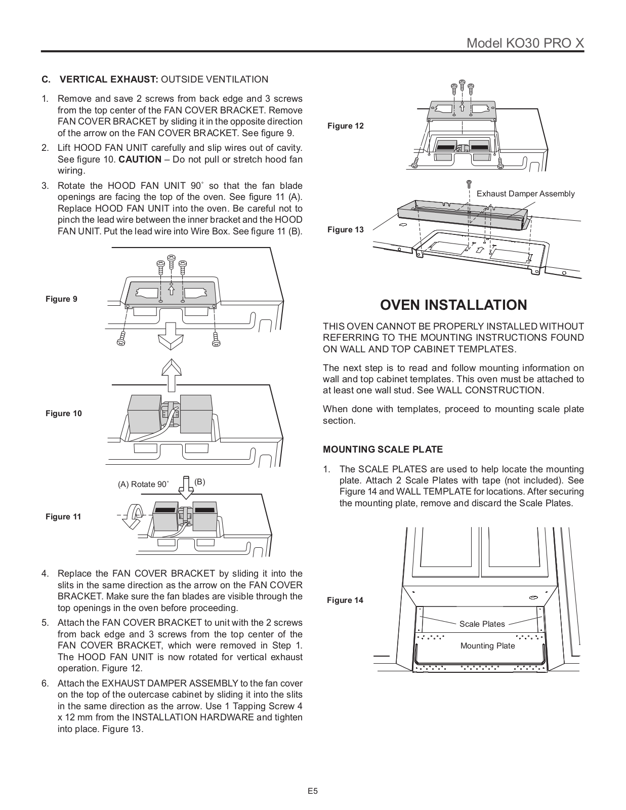
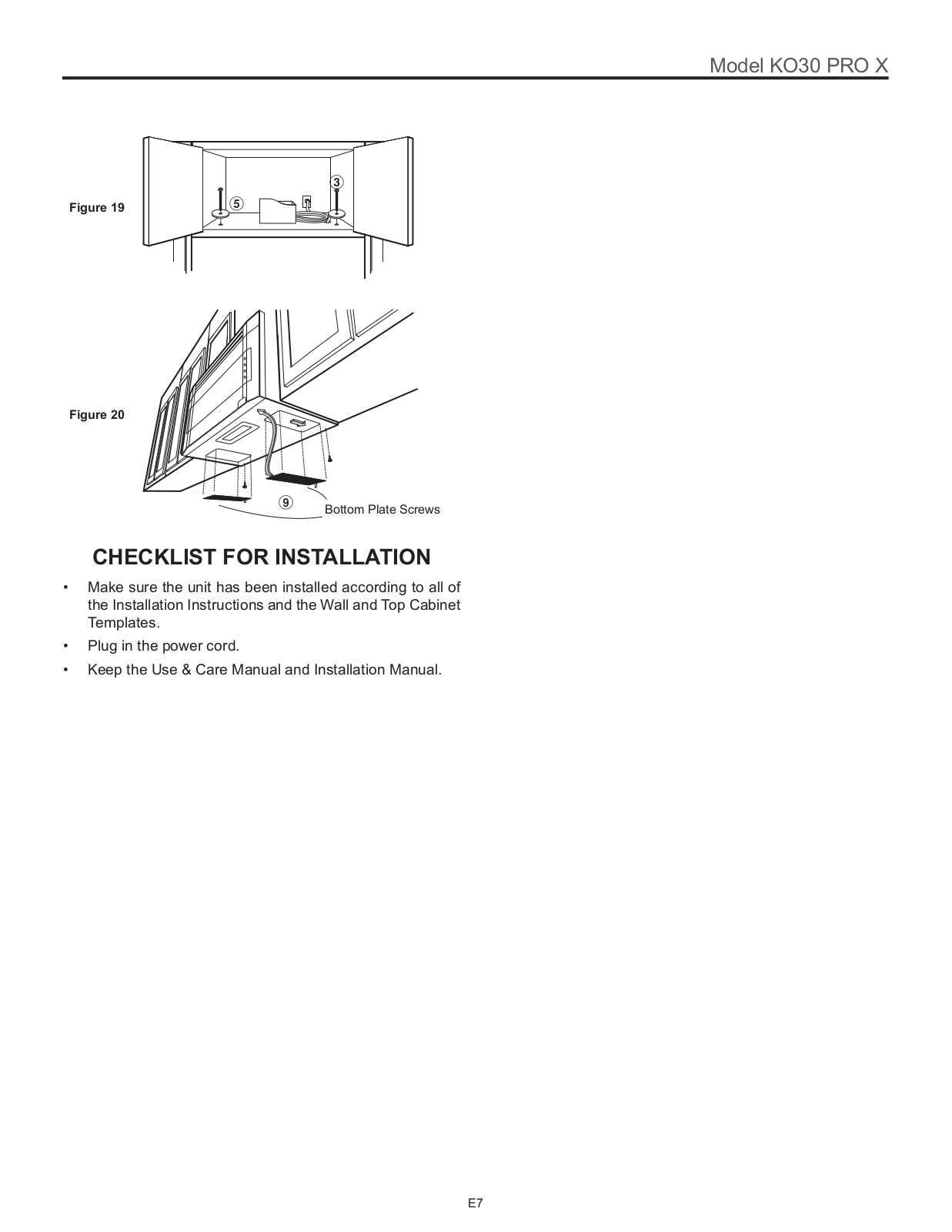
Bertazzoni KO30PROX Installation Manual
...
Bertazzoni Installation Manual
Download
Specifications and Main Features
Frequently Asked Questions
User Manual
Download
Loading...
+
hidden pages
Unhide
You need points to download manuals.
1 point = 1 manual.
You can buy points or you can get point for every manual you upload.
Buy points
Upload your manuals