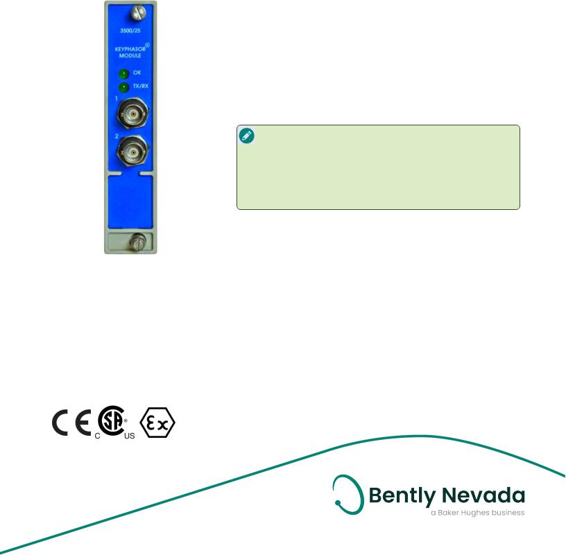
Bently Nevada 3500/25 Data sheet

3500/25 Enhanced Keyphasor Module
Datasheet
BentlyNevadaMachineryCondition Monitoring |
141532 Rev. T |
Description
The3500/25Enhanced Keyphasor Moduleis a half-height, two-channelmoduleused to provideKeyphasor signals to themonitor modules in a 3500rack. Themodulereceives input signals from proximity probes or magnetic pickups and converts thesignals to digitalKeyphasor signals that indicate when theKeyphasor mark on theshaft coincides with the Keyphasor transducer. The3500Machinery Protection System can accept up to four Keyphasor signals for normal configuration and up to eight Keyphasor signals in a paired configuration.
Keyphasor signalis a once-per-turn or multiple- event-per-turn pulsefrom a rotating shaft or gear used to providea precisetiming measurement. This allows 3500monitor modules and externaldiagnostic equipment to measureshaft rotativespeed and vector parameters such as 1Xvibration amplitudeand phase.
TheEnhanced Keyphasor Moduleis an improved 3500 system module. It offers expanded Keyphasor signal processing capabilities over theprevious design while maintaining completedownward-compatibility in terms of form, fit and function with existing Keyphasor modules for use in legacy systems. TheKeyphasor module, PWA 125792-01, is completely replaced by theupdated 149369-01module.
When a system Keyphasor input is required for TripleModular Redundant (TMR) applications, the3500system should employ two Keyphasor modules. In this configuration, the modules work in parallelto provideboth a primary and secondary Keyphasor signalto theother modules in therack.
A system with morethan four Keyphasor inputs may usea paired configuration provided thereareno morethan four

3500/25EnhancedKeyphasorModule |
|
Datasheet |
141532 Rev. T |
primary Keyphasor input signals. A paired configuration requires two consecutive monitoring positions in either theupper/lower or both half-slot positions. Four Keyphasor modules willaccept four primary and four backup input channels and providefour output channels (oneper module). A configuration of two paired and onenon-paired (three Keyphasor modules total) is also possible. In such a configuration, theuser may configure theonenon-paired Keyphasor (order either two 2-channelor one1-channeland one2channeloption)
TheIsolated Keyphasor I/Omoduleis designed for applications wheretheKeyphasor signals aretied in parallelto multipledevices and requireisolation from other systems, such as a controlsystem. TheIsolated I/Omodulewas created specifically for Magnetic Pickup applications but is compatiblewith and will provideisolation for Proximitor*applications as long as an externalpower supply is provided.
Theintent ofthis I/Omodulewas primarily to measureshaft speed and not phase. The modulecan providephasemeasurements, but this I/Ointroduces a slightly higher phaseshift than theNon-Isolated I/Oversion. Figure1 shows theamount ofphaseshift that the Isolated I/Omodules willadd at different machinespeeds.
Enhanced product features includegeneration ofonce-per-turn event signals from multi- event-per-turn inputs, field-upgradeable firmware, and asset management data reporting.
2/10

3500/25EnhancedKeyphasorModule |
|
Datasheet |
141532 Rev. T |
Specifications
Inputs
Power |
3.2 Watts typical |
Consumption |
|
|
Each KeyphasorModuleaccepts up |
|
to two transducersignals from |
|
proximity probetransducers or |
|
magnetic pickups. Theinput signal |
|
rangeis +0.8 V to -21.0 V |
Signal |
(NonIsolated I/Omodules)or+5V to |
-11V (Isolated I/Omodules). Signals |
|
|
exceeding this rangearelimited |
|
internally by themodule. Passive |
|
magnetic pickups requirea shaft |
|
rotativespeed greaterthan 200 rpm |
|
(3.3 Hz). |
Input |
21.8 k Ωminimum |
Impedance |
Signal Conditioning
|
Input rangeof 1 to 1,200,000 cpm |
|
Speed/ |
(0.017 to 20 kHz). Supports multiple |
|
events perrevolution to a maximum |
||
Frequency |
||
of 20 kHz. |
||
Signal |
||
Output rangeof 1 to 99,999 cpm |
||
Ranges |
||
|
(0.017 to 1667 Hz) |
|
Speed/ |
|
|
Frequency |
Specified at +25°C (+77°F). |
|
Signal |
||
Accuracy |
|
|
Non- |
0.017 to 100 Hz… ±1 cpm |
|
101 to 500 Hz… ±8 cpm |
||
processed |
||
Signals |
501 to 20 kHz… ±1% of cpm |
|
|
||
Processed |
0.017 to 60 Hz… ±1 cpm |
|
61 to 150 Hz… ±8 cpm |
||
Signals |
||
151 to 20 kHz… ±1% of cpm |
||
|
Transducer Conditioning
Auto |
Minimum signal amplitudefor |
|
triggering is 2 volts peak to peak and |
||
Threshold |
minimum frequency is 120 rpm (2 |
|
|
Hz). |
|
|
Useforany input above0.017 Hz(1 |
|
Manual |
rpm for1 event perrevolution). User- |
|
selectablefrom 0 to -20 volts dc. |
||
Threshold |
Minimum signal amplitudefor |
|
|
triggering is 500 millivolts peak to |
|
|
peak. |
|
Hysteresis |
User-selectablefrom 0.2 to 2.5 Volts. |
|
Outputs |
|
|
|
|
|
|
Two buffered Keyphasoroutputs are |
|
Buffered |
availableat thefront of therack via |
|
coaxial connectors. Two buffered |
||
Keyphasor |
||
Keyphasoroutputs arealso available |
||
Signals |
||
at theback of therack via Euro Style |
||
|
connectors. |
|
Output |
504 Ωmaximum buffered output |
|
Impedance |
impedance. |
|
Keyphasor |
-24 Vdc, 40 mA maximum per |
|
Transducer |
||
channel. |
||
PowerSupply |
||
Front Panel LEDs |
||
OK LED |
Indicates when a fault has been |
|
detected in theKeyphasorModule. |
||
|
||
TX/RXLED |
Indicates when theKeyphasor |
|
Moduleis communicating with the |
||
|
Rack InterfaceModule(RIM). |
|
Environmental Limits |
||
|
|
|
|
-30°C to +65°C (-22°F to +150°F) |
|
|
when used with KeyphasorI/O |
|
Operating |
Moduleotherthan theInternal Barrier |
|
version. |
||
Temperature |
0°C to +65°C (32°F to +150°F)when |
|
|
used with KeyphasorInternal Barrier |
|
|
I/OModule(Internal Termination). |
|
Storage |
-40°C to +85°C (-40°F to +185°F) |
|
Temperature |
||
Humidity |
95%, non-condensing |
|
3/10
 Loading...