

Page 1
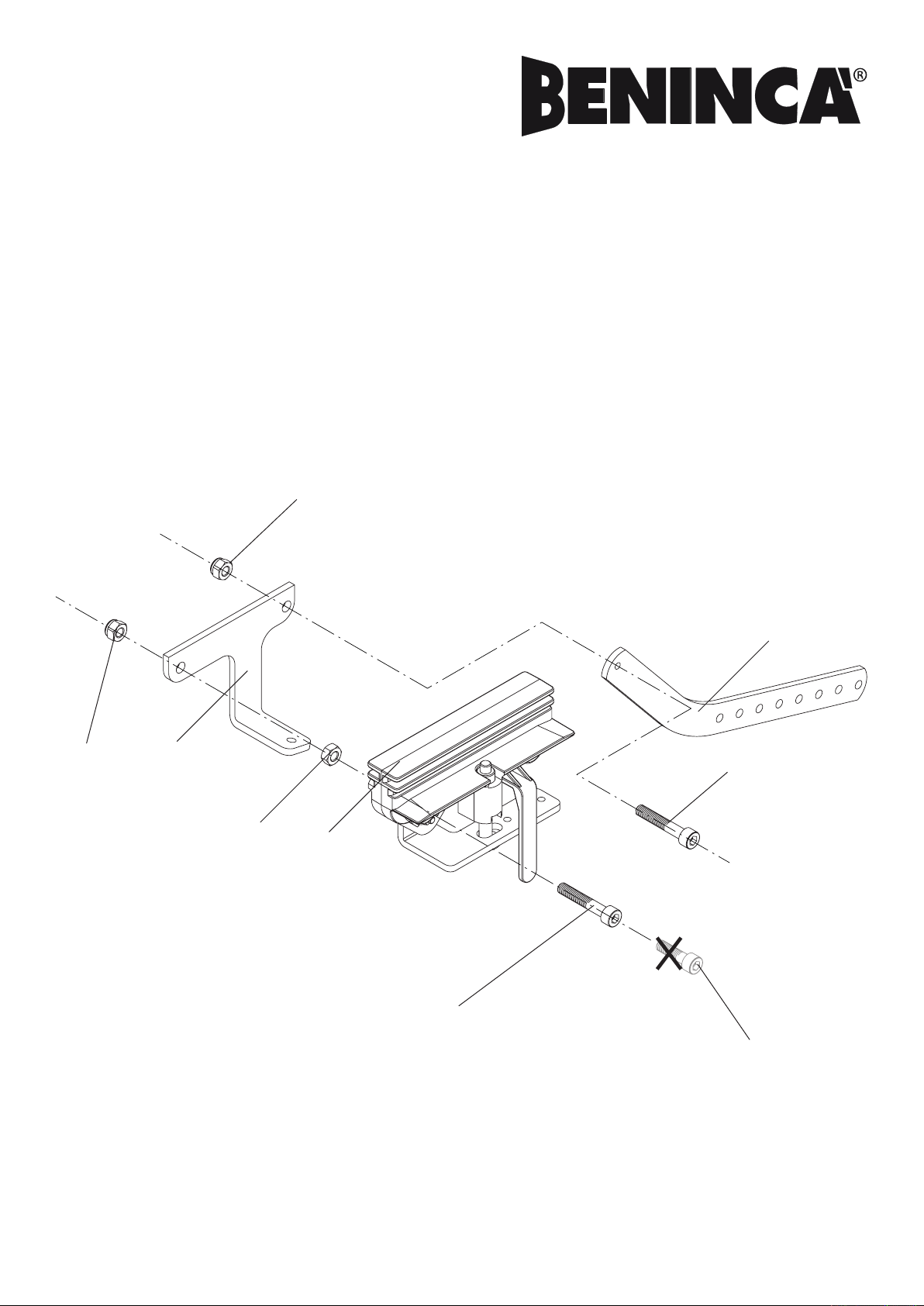
Fig.1
S
P
AU.MS25
L8542071
Rev. 01/05/00
Vite M6x35 UNI 5931
Screw M6x35 UNI 5931
Schraube M6x35 UNI 5931
Vis M6x35 UNI 5935.
Tornillo M6x35 UNI 5935.
Sruba M6x35 UNI 5935
KIT SBLOCCO A FILO.
WIRE RELEASE.
FREIGABE ÜBER DRAHT.
DÉBLOCAGE À FIL.
KIT DE DESBLOQUEO POR CABLE.
PRĘTOWY ZESTAW ODBLOKOWUJĄCY.
Vite M6x35 UNI 5931
Screw M6x35 UNI 5931
Schraube M6x35 UNI 5931
Vis M6x35 UNI 5935.
Tornillo M6x35 UNI 5935.
Sruba M6x35 UNI 5935
Vite M6x25 UNI 5931
Screw M6x25 UNI 5931
Schraube M6x25 UNI 5931
Vis M6x25 UNI 5935.
Tornillo M6x25 UNI 5935.
Sruba M6x25 UNI 5935
D1
D2
D3
T
Page 2
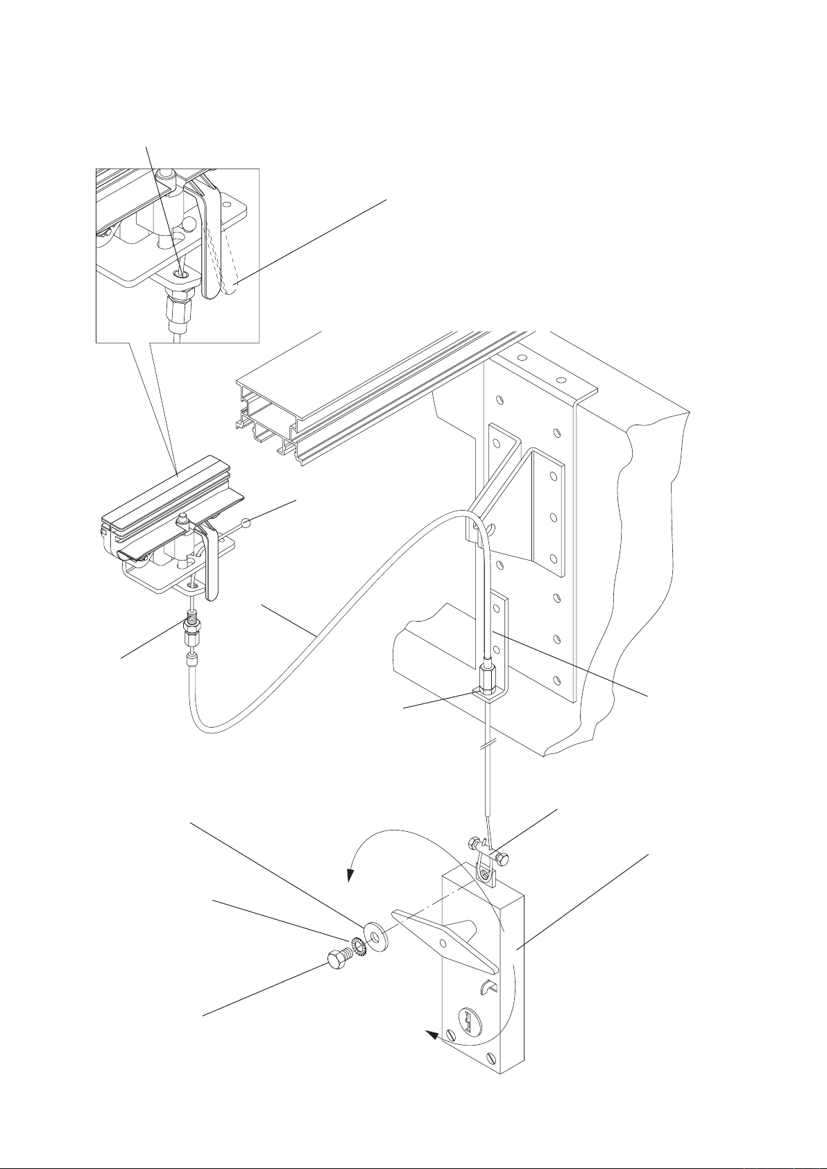
Guaina.
Sheath.
Hülse.
Gaine.
Guaina.
Osłona.
Registro.
Register.
Regulierung.
Réglage.
Reglaje.
Rejestr.
Staffa.
Support.
Stütze.
Support.
Soporte.
Zaczep.
Morsetto.
Clamp.
Klammer.
Étau.
Perrillo.
Zacisk.
Blocca.
Block.
Sperrung.
Blocage.
Bloquea.
Blokuje.
Sblocca.
Unblock.
Freigabe.
Déblocage.
Desbloquea.
Odblokowuje.
Maniglia con piastra.
Handle with plate.
Handgriff mit Platte.
Manette avec plaque.
Manilla con placa.
Uchwyt z płytą.
Rosetta per M8 DIN 6798E.
Washer M8 DIN 6798E.
Scheibe M8 DIN 6798E.
Rondelle M8 DIN 6798E.
Arandela para M8 DIN 6798E.
Podkładka dla M8 DIN 6798E.
Rosetta 9x24 UNI 6593.
Washer 9x24 UNI 6593.
Scheibe 9x24 UNI 6593.
Rondelle 9x24 UNI 6593.
Arandela 9x24 UNI 6593.
Podkładka 9x24 UNI 6593.
Vite M8x10 UNI 5739.
Screw M8x10 UNI 5739.
Schraube M8x10 UNI 5739.
Vis M8x10 UNI 5739.
Tornillo M8x10 UNI 5739.
Śruba M8x10 UNI 5739.
Cavo di acciaio.
Steel cable.
Stahlkabel.
Corde en acier.
Cable de acero.
Pręt żelazny.
Fig.2
Registro.
Register.
Regulierung.
Réglage.
Reglaje.
Rejestr.
ATTENZIONE : La vite del registro non deve sporgere.
CAUTION: the screw of the adjuster must not protrude.
ACHTUNG: Die Stellschraube darf nicht hervorragen.
ATTENTION : La vis de la rosette ne doit pas saillir.
ATENCIÓN: El tornillo del registro no debe salir.
UWAGA! Śruba regulacyjna nie może wystawać.
Per ripristinare il funzionamento automatico tirare la leva
To reset the automatic operation of the system pull the lever.
Um die automatische Funktion wieder herzustellen, den Hebel ziehen.
Pour remettre en état le fonctionnement automatique tirer le levier.
Para restablecer el funcionamiento automático tirar de la palanca.
W celu przywrócenia działania automatycznego należy pociągnąć za
dźwignię.
Page 3

1 - Applicare la staffa “S” al pattino di
trascinamento “P” (Fig.1):
A Rimuovere la vite M6x25 premontata
sul pattino e sostiturla con una delle
due viti M6x35 fornite nel kit.
B Inserire il dado esagonale standard
D1 fornito nel kit nell’apposita sede al
posto del dado autobloccante D2 da
utilizzare per ssare la staffa “F”.
C Utilizzando l’altra vite M6x35 ed il
dado autobloccante D3 presente
nel blister della staffa di traino,
completare il ssaggio della staffa.
Evitare l’eccessivo serraggio di questa
vite per non bloccare il movimento
della staffa di trascinamento “T”.
2 - Applicare il cavo di sblocco al
AU.MS25” (Fig.2):
A Inlare il cavo i metallo nel pattino di
scorrimento come indicato in Figura 2
B Avvitare il registro sulla staffa e inlare
la guaina .
C Fissare l’altro capo del cavo al
dispositivo di sblocco utilizzato. Nella
gura è rappresentato a titolo di
esempio il colegamento alla maniglia
per porte da garage AU.MS .
NOTA: E’ utilizzabile qualsiasi
dispositivo di sblocco a lo purchè
disponga di una corsa di almeno
15mm.
1 - Fit the bracket “S” to the pulling
slide “P” (Fig. 1):
A. Remove the screw M6x25 which is pre-
mounted on the slide and replace it with
one of the two screws M6x35 supplied
in the kit.
B. Insert the standard hexagonal nut D1
supplied in the kit in the appropriate
seat instead of the selocking nut D2
which must be used to t bracket “F”.
C. Complete the tting of the bracket by
using the other screw M6x35 and the
selocking nut D3, which is supplied
in the pulling bracket blister. Do not
excessively tighten this screw as it
could impair the movement of the
pulling bracket “T”.
2 - Mount the release cable onto
AU.MS25” (Fig.2):
A. Insert the metal cable in the slide, as
indicated in Figure 2.
B. Fit the adjuster on the bracket and
insert the sheath.
C. Fix the other end of the cable to the
release device. The gure shows an
example of connection to the garage
door handle AU.MS.
N.B.: Any type of cord release device
can be used under the condition that
the release stroke is of at least 15 mm.
1 – Den Bügel “S” an den Gleitschuh “P”
anbringen (Abb. 1):
A Die am Gleitschuh vormontierte Schraube
M6x25 abnehmen und mit einer der
beiden mitgelieferten Schrauben M6x35
ersetzen..
B Die mitgelieferte Standard-
Sechskantmutter D1 in den
entsprechenden Sitz anstelle der
selbstsichernden Mutter D2 einsetzen, die
zur Befestigung des Bügels „F“ verwendet
wird.
C Mit der anderen Schraube M6x35 und
der selbstsichernden Mutter D3, die sich
in der Gleitbügelverpackung bendet,
die Bügelbefestigung vollenden. Diese
Schraube darf nicht allzu sehr festgedreht
werden, um die Bewegung des
Gleitbügels „T“ nicht zu verhindern.
AU.MS25” anbringen (Abb.2):
A Das Metallkabel in den Gleitschuh, wie in
Abb. 2 gezeigt, stecken.
B Die Stellschraube am Bügel festschrauben
und die Hüslse einsetzen.
C Das andere Kabelende an die verwendete
Vorrichtung befestigen. Die Abbildung
zeigt als Beispiel den Anschluss an den
Türgriff einer Garage AU.MS .
BEMERKUNG: Es kann eine beliebige
Entsicherungsvorrichtung mit Draht
verwendet werden, vorausgesetzt sie hat
einen Hub von mindestens 15 mm.
1 – Appliquez la bride “S” au chariot
d’entraînement “P” (Fig.1):
A Enlevez la vis M6x25 pré montée sur le
chariot et substituez-la avec une des
deux vis M6x35 fournies dans le kit.
B Insérez l’écrou hexagonal standard D1
fourni dans le kit dans son logement
à la place de l’écrou de sûreté D2 à
utiliser pour xer la bride “F”.
C En utilisant l’autre vis M6x35 et l’écrou
de sûreté D3 présent dans le blister du
bras de traction, achevez le xage de
la bride. Evitez de trop serrer cette vis
à n de ne pas bloquer le mouvement
du bras de traction “T”.
2 - Appliquez le câble de
déverrouillage au AU.MS25” (Fig.2):
A Insérez le câble métallique dans le
chariot entraînement comme indiqué
dans la Figure 2
B Vissez la rosette sur la bride et insérez
la gaine.
C Fixez l’autre bout du câble au dispositif
de déblocage utilisé. La gure illustre
à titre d’exemple l’assemblage à la
poignée pour portes de garage AU.MS.
NOTA: On peut utiliser n’importe
quel dispositif de déblocage à l, à
condition qu’il ait une course d’au
moins 15mm.
1 - Aplicar el soporte “S” al patín de
arrastre “P” (Fig.1):
A Sacar el tornillo M6x25 premontado en el
patín y reemplazarlo con uno de los dos
tornillos M6x35 incluidos en el kit.
B Introducir la tuerca hexagonal estándar
D1, incluida en el kit, en el alojamiento
previsto y en lugar de la tuerca
autoblocante D2 a utilizar para jar el
soporte “F”.
C Utilizando el otro tornillo M6x35 y la
tuerca autoblocante D3 presente en el
blister del soporte de arrastre, completar
la jación del soporte. Evitar un apriete
excesivo de este tornillo para no bloquear
el movimiento del soporte de arrastre “T”.
2 - Aplicar el cable de desbloqueo al
AU.MS25” (Fig.2):
A Insertar el cable de metal en el patín de
deslizamiento como indicado en la gura
2
B Enroscar el registro sobre el soporte e
insertar la vaina.
C Fijar la otra extremidad del cable en el
dispositivo de desbloqueo utilizado. En
la gura se muestra, como ejemplo, la
conexión a la manija para puertas de
garaje AU.MS .
NOTA: se puede utilizar cualquier
dispositivo de desbloqueo con cable
siempre que disponga de una carrera
por lo menos de 15mm.
1 – Zamontować strzemiączko “S” do ślizgacza
przesuwu “P” (Rys. 1):
A Odkręcić śrubę M6x25 zamocowaną wcześniej
na ślizgaczu i zastąpić ją jedną ze śrub M6x35
znajdujących się w zestawie.
B Włożyć do swojej siedziby - w miejsce
nakrętki samoblokującej D2, standardową
nakrętkę sześciokątną D1 będącą w zestawie;
nakrętka D2 zostanie wykorzystana do
zamocowania strzemiączka.”F”:
C Dokończyć mocowania strzemiączka
przy użyciu drugiej śruby M6x35 oraz
nakrętki samoblokującej D3 znajdującej się
w wyposażeniu strzemiączka przesuwu.
Nie dokręcać zbyt mocno śruby, żeby nie
zablokować ruchu strzemiączka przesuwu „T”:
2 - Założyć do urządzenia AU.MS25 drążek
odblokowania (Rys. 2).
A Zaczepić drążek metalowy do ślizgacza
przesuwu tak, jak wskazano na rysunku 2.
B Przykręcić do strzemiączka śrubę regulacyjną i
założyć uszczelkę.
C Zamocować przeciwną końcówkę drążka
do używanego urządzenia odblokowania.
Na rysunku pokazane jest przykładowo
zamocowanie do uchwytu drzwi garażowych
AU.MS.
UWAGA! Można używać jakiegokolwiek
urządzenia odblokowania linkowego, pod
warunkiem że długość biegu wynosi co
najmniej 15 mm.
Page 4

AUTOMATISMI BENINCÀ SpA - Via Capitello, 45 - 36066 Sandrigo (VI) - Tel. 0444 751030 r.a. - Fax 0444 759728
 Loading...