


Over The Range |
Convection |
Microwave Oven |
Installation Manual |
MWOTR 30200 CSS |
EN FR |
01M-8851283200-3516-01 |
Please read this manual first!
Dear Customers!
Thank you for preferring a Beko product. We hope that you get the best results from your product which has been manufactured with high quality and state-of-the-art technology. Therefore, please read this entire user manual and all other accompanying documents carefully before using the product and keep it as a reference for future use. If you handover the product to someone else, give the user manual as well. Follow all warnings and information in the user manual.
Meanings of the Symbols
Following symbols are used in the various section of this manual:
C
A
B

 Warning for hot surfaces.
Metallic containers for food and beverages are not allowed during microwave cooking.
Care should be taken not to displace the turntable when removing containers from the appliance.
The appliance shall not be cleaned with a steam cleaner.
This product has been manufactured in environmental friendly modern plants without giving any harm to the nature.

CONTENTS
1 Important instructions |
4 |
1.1 General safety........................................................... |
4 |
1.1.1 Electrical safety...................................................... |
5 |
2 Your over the range convection |
|
microwave oven |
6 |
2.1 Overview...................................................................... |
6 |
2.2 Technical data........................................................... |
6 |
3 Mounting space |
7 |
4 External exhaust |
8 |
4.1 Installing hood exhaust........................................ |
8 |
4.1.1 Outside top exhaust (example only)............ |
8 |
4.1.2 Outside back exhaust (example only)......... |
9 |
4.1.3 Exhaust connection............................................ |
9 |
4.1.4 Maximum duct length...................................... |
10 |
4.1.5 Elbows, transitions, wall and roof caps, |
|
etc.,......................................................................................10 |
|
4.2 Damage – shipment / installation................... |
11 |
4.3 Parts included.......................................................... |
11 |
4.3.1 Hardware packet................................................. |
11 |
4.3.2 Additional parts.................................................. |
12 |
4.4 Tools and materials needed............................. |
13 |
5 Installation |
14 |
5.1 Placement of the mounting plate................... |
14 |
5.1.1 Removing the microwave oven from the |
|
carton/ removing the mounting plate.................. |
14 |
5.1.2 Finding the wall studs...................................... |
14 |
5.1.3 Determining wall plate location |
|
under your cabinet....................................................... |
14 |
5.1.4 Aligning the wall plate..................................... |
16 |
5.2 Installation types (choose A, B or C).............. |
17 |
5.2.1 Outside top exhaust |
|
(vertical duct type A)................................................... |
17 |
5.2.2 Outside back exhaust |
|
(horizontal duct type B)............................................. |
23 |
5.2.3 Recirculating |
|
(non-vented ductless type C).................................. |
28 |
6 How to use the product |
32 |
Over The Range Convection Microwave Oven / Installation Manual |
3 / 63 EN |
|
|

1 Important instructions
1.1 General safety
C Read and save these instructions
Doing so will:
•make installation easier.
•help you in the future if you have questions.
•help if you have an electrical inspection.
Call your dealer when you have questions or need service. When you call, you will need the microwave model and serial numbers.
WARNING: To reduce the risk of fire, electric A shock, or injury to persons, always exercise basic safety precautions, in-
cluding the following:
Read all instructions before using the appliance.
This product requires a three-prong grounded outlet. The installer must perform a ground continuity check on the power outlet box before beginning the installation to insure that the outlet box is properly grounded.
If not properly grounded, or if the outlet box does not meet electrical requirements noted (under ELECTRICAL REQUIREMENTS), a qualified electrician should be employed to correct any deficiencies.
For personal safety, remove house fuse or open circuit breaker before beginning installation to avoid severe or fatal shock injury.
For personal safety, the mounting surface must be capable of supporting the cabinet load, in addition to the added weight of this 63–85 pound (28.5–38.5 kg) product, plus additional oven loads of up to 50 pounds (22.7 kg) or a total weight of 113–135 pounds (51.3–61.2 kg).
For personal safety, this product cannot be installed in cabinet arrangements such as an island or a peninsula. It must be mounted to BOTH a top cabinet AND a wall.
For easier installation and personal safety, it is recommended that two people install this product.
For personal safety, this appliance must be properly grounded to avoid severe or fatal shock.
4 / 63 EN |
Over The Range Convection Microwave Oven / Installation Manual |
|
|

1 Important instructions
The power cord of this appliance is equipped with a three-prong (grounding) plug which mates with a standard three-prong (grounding) wall receptacle to minimize the possibility of electric shock hazard from this appliance.
Do not, under any circumstances, cut, deform or remove any of the prongs from the power cord. Do not use with an extension cord.
1.1.1 Electrical safety
Product rating is 120 volts AC, 60 Hertz, 15 amps and 1500 watts. This product must be connected to a supply circuit of the proper voltage and frequency.
Wire size must conform to the requirementsoftheNationalElectrical Code or the prevailing local code for this kilowatt rating. The power supply cord and plug should be brought to a separate 15to 20ampere branch circuit single grounded outlet. The outlet box should be located in the cabinet above the microwave oven. The outlet box and supply circuit should be installed by a qualified electrician and conform to the National Electrical Code or the prevailing local code.
Over The Range Convection Microwave Oven / Installation Manual |
5 / 63 EN |
|
|
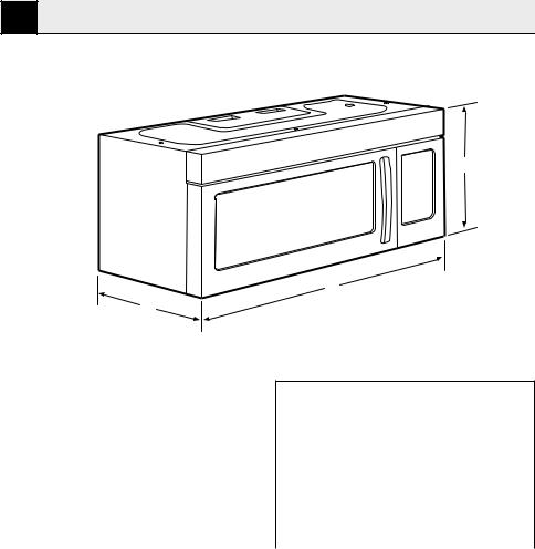
2 Your over the range convection microwave oven
2.1 Overview
A
B
C
2.2 Technical data |
|
|
|
Product Dimensions |
|
|
|
A-Height |
15.7 ˝ (39.9 cm) |
|
|
B-Width |
29.9 ˝ (75.9 cm) |
|
|
C-Depth |
15.0 ˝ (38.1 cm) |
|
|
Cutout Dimensions
Height (Min.) |
16.75 ˝ (42.5 cm) |
|
|
Height (Max.) |
17.0 ˝ (43.2 cm) |
|
|
Width (Min.) |
30.0 ˝ (76.2 cm) |
|
|
Depth (Min.) |
12.0 ˝ (30.5 cm) |
|
|
Depth (Max.) |
13.0 ˝ (33.0 cm) |
|
|
6 / 63 EN |
Over The Range Convection Microwave Oven / Installation Manual |
|
|

3 Mounting space
[12“ (30.5 cm) min.]
163⁄4 “ (42.5 cm)
30“ (76.2 cm)
 2“ (5.1 cm)
Bottom Edge of Cabinet Needs to be 30 (76.2 cm)
 or More from the Cooking Surface
30“
(76.2 cm) min.
Backsplash
66 (167.6 cm) or More from the Floor to the Top of the Microwave
C The space between the cabinets must be 30“ (76.2 cm)wide and free of obstructions.
If you are going to vent your micro- C wave oven to the outside, see Hood Exhaust Section for exhaust duct
preparation.
When installing the microwave oven C beneath smooth, flat cabinets, be careful to follow the instructions on the top cabinet template for power
cord clearance.
Over The Range Convection Microwave Oven / Installation Manual |
7 / 63 EN |
|
|
4 External exhaust
4.1 Installing hood exhaust
C |
|
Read these instructions only if you |
|
|
|
|
|
|
|||||||||
|
plan to vent your exhaust to the out- |
|
|
|
|
|
|
||||||||||
|
side. If you plan to recirculate the air |
|
|
|
|
|
|
||||||||||
|
|
|
|
|
|
|
back into the room, proceed to title 5 |
|
|
|
|
|
|
||||
4.1.1 Outside top exhaust |
|
|
|
|
|
||||||||||||
(example only) |
|
|
|
|
|
||||||||||||
The following chart describes an example of one |
|
|
|
|
|
||||||||||||
possible ductwork installation. |
|
|
|
|
|
||||||||||||
|
|
|
|
|
|
|
|
|
|
|
|
|
|
|
|
|
|
|
|
|
|
|
|
|
|
Duct pieces |
Equivalent |
x |
Number |
= |
Equivalent |
||||
|
|
|
|
|
|
|
|
|
|
|
|
|
Length |
used |
Length |
||
|
|
|
|
|
|
|
|
|
|
|
Roof Cap |
24 Ft. (7.3 m) |
x |
(1) |
= |
24 Ft. (7.3 m) |
|
|
|
|
|
|
|
|
|
|
|
|
|
|
|
|
|
|
|
|
|
|
|
|
|
|
|
|
|
|
|
|
|
|
|
|
|
|
|
|
|
|
|
|
|
|
|
|
12 Ft. (3.6 m) |
12 Ft. (3.6 m) |
x |
(1) |
= |
12 Ft. (3.6 m) |
|
|
|
|
|
|
|
|
|
|
|
|
|||||||
|
|
|
|
|
|
|
|
|
|
|
Straight Duct |
|
|
|
|
|
|
|
|
|
|
|
|
|
|
|
|
|
(6”/15.2 cm |
|
|
|
|
|
|
|
|
|
|
|
|
|
|
|
|
|
Round) |
|
|
|
|
|
|
|
|
|
|
|
|
|
|
|
|
|
|
|
|
|
|
|
|
|
|
|
|
|
|
|
|
|
|
|
Rectangular-to- |
5 Ft. (1.5 m) |
x |
(1) |
= |
5 Ft. (1.5 m) |
|
|
|
|
|
|
|
|
|
|
|
|
Round |
|
|
|
|
|
|
|
|
|
|
|
|
|
|
|
|
|
Transition Adap- |
|
|
|
|
|
|
|
|
|
|
|
|
|
|
|
|
|
tor* |
|
|
|
|
|
|
|
|
|
|
|
|
|
|
|
|
|
|
|
|
|
|
|
|
|
|
|
|
|
|
|
|
|
|
|
|
|
|
|
|
|
|
|
|
|
|
|
|
|
|
Equivalent lengths of duct pieces are based on actual tests |
|
Total Length |
= |
41 Ft. (12.5 m) |
|||||
|
|
|
|
|
|
|
|
and reflect requirements for good venting performance |
|
|
|
|
|||||
|
|
|
|
|
|
|
|
with any vent hood. |
|
|
|
|
|
||||
|
|
|
|
|
|
|
|
|
|
|
|
|
|||||
|
|
|
|
|
|
|
|
|
|
|
|
|
|
|
|
|
|
If a rectangular-to-round transition C adaptor is used, the bottom corners of the damper will have to be cut to fit, using the tin snips, in order to al-
low free movement of the damper.
8 / 63 EN |
Over The Range Convection Microwave Oven / Installation Manual |
|
|
4 External exhaust
4.1.2 Outside back exhaust (example only)
The following chart describes an example of one possible ductwork installation.
Duct pieces |
Equivalent |
x |
Number |
= |
Equivalent |
|||
|
|
|
|
Length |
used |
Length |
||
|
|
|
Wall Cap |
40 Ft. (12.2 m) |
x |
(1) |
= |
40 Ft. (12.2 m) |
|
|
|
|
|
|
|
|
|
|
|
|
3 Ft. Straight |
3 Ft. (0.9 m) |
x |
(1) |
= |
3 Ft. (0.9 m) |
|
|
|
||||||
|
|
|
Duct (31⁄4” x |
|
|
|
|
|
|
|
|
10”/8.2 x 25.4 |
|
|
|
|
|
|
|
|
cm Rectangular) |
|
|
|
|
|
|
|
|
|
|
|
|
|
|
|
|
|
|
|
|
|
|
|
|
|
|
90° Elbow |
10 Ft. (3 m) |
x |
(2) |
= |
20 Ft. (3 m) |
|
|
|
|
|
|
|
|
|
Equivalent lengths of duct pieces are based on actual tests |
|
Total Length |
= |
63 Ft. (19.2 m) |
||||
and reflect requirements for good venting performance with |
|
|
|
|
||||
any vent hood. |
|
|
|
|
|
|||
For back exhaust, care should be taken to align exhaust with space be- C tween studs, or wall should be prepared at the time it is constructed by leaving enough space between the wall studs to accommodate exhaust.
If you need to install ducts, note that the total duct length of 31⁄4” x C 10” (8.2 x 25.4 cm) rectangular or 6” (15.2 cm) diameter round duct should not exceed 120 equivalent
feet (36.5 m).
Outside ventilation requires a HOOD EXHAUST DUCK. Read the following carefully. It is important that venting be installed using the most direct
C route and with as few elbows as possible. This ensures clear venting of exhaust and helps prevent blockages. Also, make sure dampers swing freely and nothing is blocking the ducts.
4.1.3 Exhaust connection
The exhaust adaptor has been designed to mate with a standard 31⁄4” x 10” (8.2 x 25.4 cm) rectangular duct. If a round duct is required, a rectangu- lar-to-round transition adaptor must be used. Do not use less than a 6” 6” (15.2 cm) diameter duct.
Over The Range Convection Microwave Oven / Installation Manual |
9 / 63 EN |
|
|

4 External exhaust
4.1.4 Maximum duct length
For satisfactory air movement, the total duct length of 31⁄4” x 10” (8.2 x 25.4 cm) rectangular or 6” (15.2 cm) diameter round duct should not exceed 120 equivalent feet (36.5 m).
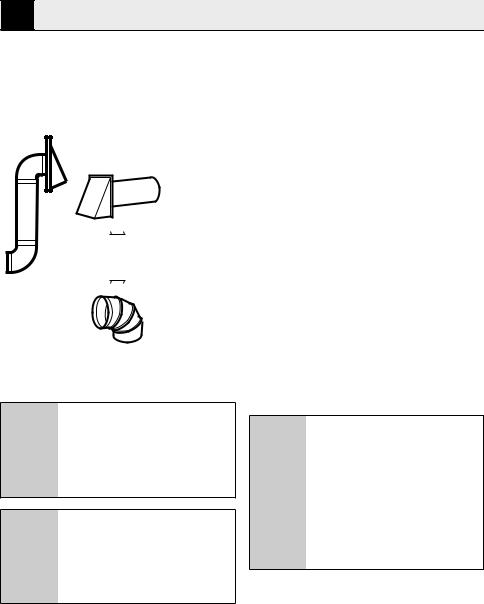
4.1.5 Elbows, transitions, wall and roof caps, etc.,
Present additional resistance to airflow and are equivalent to a section of straight duct which is longer than their actual physical size. When calculating the total duct length, add the equivalent lengths of all transitions and adaptors plus the length of all straight duct sections. The chart below shows you how to calculate total equivalent ductwork length using the approximate feet of equivalent length of some typical ducts.
Duct pieces |
Equivalent |
x |
Number |
= |
Equivalent |
|
Length |
used |
Length |
||
Rectangular-to-Round |
5 Ft. (1.5 m) |
x |
( ) |
= |
Ft. or m |
Transition Adaptor* |
|
|
|
|
|
Wall Cap |
40 Ft. (12.2 m) |
x |
( ) |
= |
Ft. or m |
90° Elbow |
10 Ft. (3 m) |
x |
( ) |
= |
Ft. or m |
45° Elbow |
45° Elbow |
x |
( ) |
= |
Ft. or m |
90° Elbow |
25 Ft. (7.6 m) |
x |
( ) |
= |
Ft. or m |
10 / 63 EN |
Over The Range Convection Microwave Oven / Installation Manual |
|
|
4 External exhaust
|
|
|
45° Elbow |
5 Ft. (1.5 m) |
x |
( ) |
= |
Ft. or m |
|
|
|
|
|
|
|
|
|
|
|
|
Roof Cap |
24 Ft. (7.3 m) |
x |
( ) |
= |
Ft. or m |
|
|
|
|
|
|
|
|
|
|
|
|
Straight Duct 6“ (15.2 cm) |
1 Ft. (0.3 m) |
x |
( ) |
= |
Ft. or m |
|
|
|
||||||
|
|
|
Round or |
|
|
|
|
|
|
|
|
31⁄4” x 10” (8.2 x 25.4 |
|
|
|
|
|
|
|
|
cm) rectangula |
|
|
|
|
|
|
|
|
|
|
|
|
|
|
|
|
|
|
|
|
Total Ductwork |
= |
Ft. or m |
|
|
|
|
|
|
|
|
|
If a rectangular-to-round transition C adaptor is used, the bottom corners of the damper will have to be cut to fit, using the tin snips, in order to al-
low free movement of the damper.
For back exhaust, care should be taken to align exhaust with space be- C tween studs, or wall should be prepared at the time it is constructed by leaving enough space between the wall studs to accommodate exhaust.
4.2 Damage – shipment / installation
•• If the unit is damaged in shipment, return the unit tı the store in which it was bought for repair or replacement.
•• If the unit is damaged by the customer, repair or replacement is the responsibility of the customer.
•• If the unit is damaged by the installer /if other than the customer), repair or replacement must be made by arrangement between customer and installer.
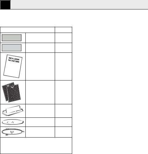
4.3 Parts included
4.3.1 Hardware packet
Part |
Quantity |
Wood Screws |
2 |
(1⁄4“ x 2“) |
|
Toggle Bolts (and |
2 |
wing nuts) (3⁄16“ |
|
x 3“) |
|
Self-Aligning Machine |
3 |
Screws |
|
(1⁄4“-28 x 31⁄4“) |
|
Nylon Grommet |
1 |
(for metal cabinets) |
|
You will find the installation hardware contained in a packet with the unit. Check to make sure you have all these parts.
NOTE: Some extra parts are included.
Over The Range Convection Microwave Oven / Installation Manual |
11 / 63 EN |
|
|
4 External exhaust
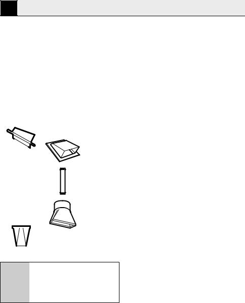
4.3.2 Additional parts
Part |
Quantity |
To p C abinet |
1 |
Template and |
|
Rear Wall Template |
1 |
Installation |
1 |
Instructions |
|
Separately Packed |
2 |
Grease Filters |
|
Exhaust adaptor |
1 |
Glass tray |
1 |
Turntable ring |
1 |
You will find the installation hardware contained in a packet with the unit. Check to make sure you have all these parts.
NOTE: Some extra parts are included.
12 / 63 EN |
Over The Range Convection Microwave Oven / Installation Manual |
|
|
4 External exhaust
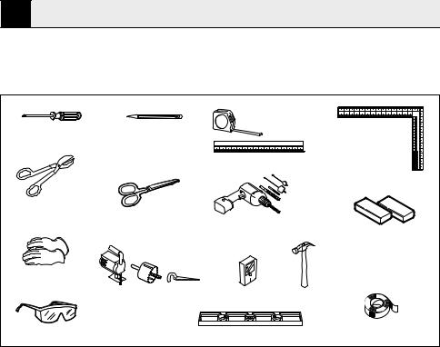
4.4 Tools and materials needed
# 1 Phillips screwdriver |
Pencil |
|
Tin snips (for cutting |
|
damper, if required) |
Scissors |
|
|
|
(to cut template, if necessary) |
Gloves
Saw (saber, hole or keyhole)
Ruler or tape measure and straight edge
Electric drill with 3⁄16“, 1⁄2“ and5⁄8“ drill bits
Stud nderor Hammer (optional)
Carpenter square (optional)
Filler blocks or scrap wood pieces, if needed for top cabinet spacing (used on recessed botto cabinet installations only
Safety goggles |
Level |
Duct and masking tape |
|
Over The Range Convection Microwave Oven / Installation Manual |
13 / 63 EN |
|
|
5 Installation
5.1 Placement of the mounting plate
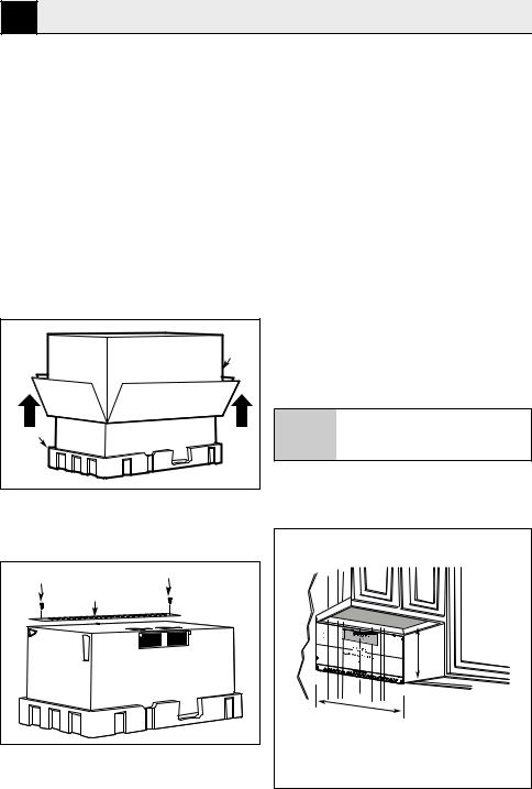
5.1.1 Removing the microwave oven from the carton/ removing the mounting plate
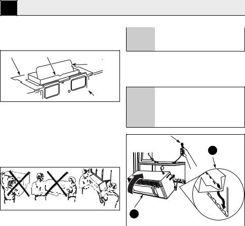
1.Remove the installation instructions, filters, glass tray and the small hardware bag. Do not remove the Styrofoam protecting the front of the oven.
2.Fold back all 4 carton flaps fully against carton sides. Then carefully roll the oven and carton over onto the top side. The oven should be resting in the Styrofoam.
Carton |
Styrofoam |
3.Pull the carton up and off the oven.
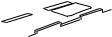
4.Cut the middle of the outer protective plastic bag to remove the mounting plate
Screws |
Screws |
|
Mounting Plate |
||
|
5.Remove the screws from the mounting plate. This plate will be used as the rear wall template and for mounting. Reinstall the screws into the holes where they were removed.
5.1.2 Finding the wall studs
1. Find the studs, using one of the following methods:
•• Stud finder – a magnetic device which locates nails.
•• Use a hammer to tap lightly across the mounting surface to find a solid sound. This will indicate a stud location.
2.After locating the stud(s), find the center by probing the wall with a small nail to find the edges of the stud. Then place a mark halfway between the edges. The center of any adjacent studs should be 16“ (40.6 cm) or 24“ (61 cm) from this mark.
3.Draw a line down the center of the studs.
A WARNING: The microwave must be connected to at least one wall stud.
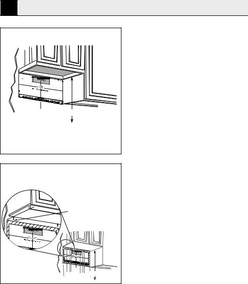
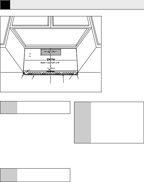
5.1.3 Determining wall plate location under your cabinet
Plate position—beneath at bottom cabinet
16-1/2ʺ
C
L
At least 30ʺ
Draw a vertical line on the wall at the center of the 30ʺ wide space. Tape the Rear Wall Template onto the wall matching the centerline and touching the bottom of the cabinet.
14 / 63 EN |
Over The Range Convection Microwave Oven / Installation Manual |
|
|
5 Installation
Plate position—beneath framed recessed cabinet bottom
C |
|
L |
33ʺ to Cooktop |
|
Draw a vertical line on the wall at the center of the 30ʺ space.
Tape the Rear Wall Template onto the wall matching the centerline and touching the bottom cabinet frame.
The microwave must be level.
Use a level to make sure the cabinet bottom is level.
If the cabinets have a front overhang only, with no back or side frame, install the mounting plate down the same distance as the front overhang depth. This will keep the microwave level.
1.Measure the inside depth of the front overhang.
2.Draw a horizontal line on the back wall an equal distance below the cabinet bottom as the inside depth of the front overhang.
3.For this type of installation with front overhang only, align the mounting tabs with this horizontal line, not touching the cabinet bottom as described in subtitle 5.1.4.
Plate position—beneath recessed bottom cabinet with front overhang
Draw a line on the
back wall equal to the depth of the front
overhang.
C
L
33" to Cooktop
Your cabinets may have decorative trim that interferes with the microwave installation. Remove the decorative trim to install the microwave properly and to make it level
Over The Range Convection Microwave Oven / Installation Manual |
15 / 63 EN |
|
|
5 Installation
Hole B
Horizontal Line |
Area E |
12" 
4"
Centerline notches
C
L
Draw a Vertical Line on Wall from Center of Top Cabinet
Hole A Horizontal Line
Draw a Horizontal line on wall from bottom of “Rear Wall Template”.
A Wear gloves to avoid cutting fingers on sharp edges.
5.1.4 Aligning the wall plate
1.Draw a Vertical line on the wall at the center of the 30” wide space.
2.Draw a Horizontal line on the wall at the bottom of “Rear Wall Template”.
3.Drill 5/8” holes for toggle bolts on 2 locations (Hole A, Hole B) but if the location of hole is same as that of stud, drill a 3/16” hole for wood screw. In other words, toggle bolt can not be used to the location of stud.
C DO NOT MOUNT THE PLATE AT THIS TIME.
Holes A and B are inside area E. If both of A and B are not in a stud, find a stud somewhere in area E and
C draw a forth circle to line up with the stud. It is important to use at least one wood screw mounted firmly in a stud to support the weight of the microwave. Set the mounting plate aside.
16 / 63 EN |
Over The Range Convection Microwave Oven / Installation Manual |
|
|

5 Installation
5.2 Installation types (choose A, B or C)
this microwave oven is designed for adaptation to the following three types of ventilation:
•• Outside Top Exhaust (Vertical Duct Type A)
Adaptor in Place for |
Outside Top Exhaust |
•• Outside Back Exhaust (Horizontal Duct Type B)
Adaptor Must Be
Moved to the Back for
Outside Back Exhaust
This microwave is shipped assem- C bled for Recirculating. Select the type of ventilation required for your installation and proceed to that sec-
tion.
5.2.1 Outside top exhaust (vertical duct type A)
installation overview
A1. Attach Mounting Plate to Wall
A2. Prepare Top Cabinet
A3. Adapting Microwave Blower for
A4. Check Damper Operation
A5. Mount Microwave Oven
A6. Adjust Exhaust Adaptor
A7. Connect Ductwork
Make sure the screws for the blower A motor and blower plate are securely tightened when they are reinstalled.
This will help to prevent excessive vibration.
A Make sure the motor wiring has been properly routed and secured, and that the wires are not pinched.
•• Recirculating (Non-Vented Ductless Type C)
Over The Range Convection Microwave Oven / Installation Manual |
17 / 63 EN |
|
|

5 Installation
A1. Attach Mounting Plate to Wall
Attach the plate to the wall using toggle bolts. At least one wood screw must be used to attach the plate to a wall stud.
1.Remove the toggle wings from the bolts.
2.Insert the bolts into the mounting plate through the holes designated to go into drywall and reattach the toggle wings to 3⁄4” (19 mm) onto each bolt.
To use toggle bolts:
A Be careful to avoid pinching fingers between the back of the mounting plate and the wall.
4.Tighten all bolts. Pull the plate away from the wall to help tighten the bolts.
A2. Use top cabinet template For preparation of top Cabinet
You need to drill holes for the top support screws, a hole large enough for the power cord to fit through, and a cutout large enough for the exhaust adaptor.
|
Spacing for Toggles |
|
More Than Wall |
|
Thickness |
Mounting |
Toggle Wings |
Toggle |
|
Plate |
Bolt |
|
Wall |
|
Bolt End |
3.Place the mounting plate against the wall and insert the toggle wings into the holes in the wall to mount the plate.
Before tightening toggle bolts and wood screw, make sure the tabs on C the mounting plate touch the bottom of the cabinet when pushed flush against the wall and that the plate is properly centered under the
cabinet.
•• Read the instructions on the TOP CABINET TEMPLATE.
•• Tape it underneath the top cabinet.
•• Drill the holes, following the instructions on the TOP CABINET TEMPLATE.
A Wear safety goggles when drilling holes in the cabinet bottom.
18 / 63 EN |
Over The Range Convection Microwave Oven / Installation Manual |
|
|

5 Installation
A3. Adapting microwave blower for outside top exhaust
1.Place the microwave in its upright position, with the top of the unit facing up. Remove the screw that holds the blower plate to the microwave. Remove and save the screw holding the blower motor to the microwave.
 Blower Plate
Back of
 Microwave
Blower Motor

 Screw
Screw
2.Carefully pull out the blower unit. The wires will extend far enough to allow you to adjust the blower unit.
End B
End A

Back of
Microwave
3.Roll the blower unit 90° so that fan blade openings are facing out the top of the microwave.
Before Rotation |
After Rotation |
Back of |
Back of |
Microwave |
Microwave |
4. Place the blower unit back into the opening.
AFTER: Fan Blade |
|
Openings Facing |
Top |
|
Back of |
|
Microwave |
5.Secure blower unit to microwave with the screw removed in Step 1. Make sure the screw is tight.
6.Replace blower plate with the screw removed in Step 1. Make sure the screw is tight.
Back of
 Microwave
7.Attach the exhaust adaptor to the top of the blower plate by sliding it into the guides of the blower plate. Push in securely until it is in the locking tabs. Take care to assure that the damper hinge is installed so that the damper swings freely.
Adaptor
Guide
Back of
 Microwave
Locking Tab
Over The Range Convection Microwave Oven / Installation Manual |
19 / 63 EN |
|
|
5 Installation
A4. Check for proper damper opera- |
|
If filler blocks are not used, case |
|
tion |
A damage may occur from overtight- |
|
ening screws. |
Blower Plate |
Exhaust Adaptor |
1. Lift microwave, tilt it forward, and hook slots |
|||
|
|
||||
|
Damper |
at back bottom edge onto four lower tabs of |
|||
|
|
mounting plate. |
|
|
|
|
|
2. Rotate front of oven up against cabinet bottom. |
|||
|
Back of |
When |
mounting |
the |
microwave |
|
Microwave |
oven, thread power cord through |
|||
|
|
||||
•• Make sure tape securing damper is removed |
hole in bottom of top cabinet. Keep |
||||
and damper pivots easily before mounting |
C it tight throughout Steps 1–3. Do not |
||||
microwave. |
|
pinch cord or lift oven by pulling cord. |
|||
•• You will need to make adjustments to assure |
|
|
|
|
|
proper alignment with your house exhaust duct |
|
|
|
|
|
after the microwave is installed. |
|
|
1 |
|
|
A5. Mount the microwave oven |
|
|
|
||
|
|
|
|
||
2 |
C |
For easier installation and person- |
|
|
|
|
|
|||
al safety, we recommend that two |
3. Insert a self-aligning screw through top center |
|||
people install this microwave oven. |
||||
|
|
|
cabinet hole. Temporarily secure the oven by |
|
|
|
|
turning the screw at least two full turns after |
|
A |
Do not grip or use handle during in- |
|||
|
the threads have engaged. (It will be completely |
|||
stallation. |
|
tightened later.) Be sure to keep power cord |
||
|
|
|
tight. Be careful not to pinch the cord, especially |
|
|
|
|||
|
|
|
when mounting flush to bottom of cabinet. |
|
C |
If your cabinet is metal, use the ny- |
|||
lon grommet around the power cord |
|
|
||
hole to prevent cutting of the cord. |
|
|
||
|
|
|
|
|
C |
We recommend using filler blocks if |
|
|
|
the cabinet front hangs below the |
|
|
||
cabinet bottom shelf. |
|
|
||
20 / 63 EN |
Over The Range Convection Microwave Oven / Installation Manual |
|
|
 Loading...