


DIGITAL PRO MIXER DDM4000
User Manual
A50-16713-00001

DIGITAL PRO MIXER DDM4000
Important Safety Instructions
Caution
+To reduce the risk of electric shock, do not remove the top cover (or the rear section). No user serviceable parts inside. Refer servicing to qualifi ed personnel.
+To reduce the risk of fi re or electric shock, do not expose this appliance to rain and moisture. The apparatus shall not be exposed to dripping or splashing liquids and no objects fi lled with liquids, such as vases, shall be placed on the apparatus.
This symbol, wherever it appears, alerts you to the presence of uninsulated dangerous voltage inside the enclosure - voltage that may be suffi cient to constitute a risk of shock.
This symbol, wherever it appears, alerts you to important operating and maintenance instructions in the accompanying literature. Please read the manual.
1)Read these instructions.
2)Keep these instructions.
3)Heed all warnings.
4)Follow all instructions.
5)Do not use this apparatus near water.
6)Clean only with dry cloth.
7)Do not block any ventilation openings. Install in accordance with the manufacturer’s instructions.
8)Do not install near any heat sources such as radiators, heat registers, stoves, or other apparatus (including amplifi ers) that produce heat.
9)Do not defeat the safety purpose of the polarized or grounding-type plug.Apolarized plug has two blades with one wider than the other. A grounding-type plug has two blades and a third grounding prong. The wide blade or the third prong are provided for your safety. If the provided plug does not fi t into your outlet, consult an electrician for replacement of the obsolete outlet.
10)Place the power cord so that it is protected from being walkedonandsharpedges.Besurethatthepowercordis protected particularly at plugs, convenience receptacles and the point where it exits from the apparatus.
11)The apparatus shall be connected to a MAINS socket outlet with a protective earthing connection.
12)Where the MAINS plug or an appliance coupler is used as the disconnect device, the disconnect device shall remain readily operable.
13)Only use attachments/accessories specified by the manufacturer.
14)Use only with the cart, stand, tripod, bracket, or table specifi ed by the manufacturer, or sold with the apparatus. When a cart is used, use caution when moving the cart/ apparatus combination to avoid injury from tip-over.
15)Unplug this apparatus during lightning storms or when unused for long periods of time.
16)Refer all servicing to qualifi ed service personnel. Servicing is required when the apparatus has been damaged in any way, such as power supply cord or plug is damaged, liquid has been spilled or objects have fallen into the apparatus,theapparatushasbeenexposedtorainormoisture, does not operate normally, or has been dropped.
Caution
+These service instructions are for use by qualifi ed service personnel only. To reduce the risk of electric shock do not perform any servicing other than that contained in the operation instructions. Repairs have to be performed by qualifi ed service personnel.
2 |
|

DIGITAL PRO MIXER DDM4000
DIGITAL PRO MIXER
Ultimate 5-Channel Digital DJ Mixer with Sampler, 4 FX Sections, Dual BPM Counters and MIDI
== |
|
DDM4000 |
32-bit digital DJ mixer with beat-synchronized sampler, 4 multi-FX sections, 2 patented1 BPM coun- |
||
|
ters, digital crossfader and MIDI |
|
== |
4 Phono/Line stereo channels allowing max. 8 signal sources to be connected simultaneously |
|
== 2 Microphone inputs with Gain, EQ, Talk function and FX
== 4 stereo channels with Gain, programmable parametric 3-band EQ with Kill function, fader curve control and flexible crossfader assignment
== Fully featured MIDI controller for your DJ software
== Sophisticated sampler with beat-controlled loop function, real-time pitch control, sampler FX and crossfader start option
== 2 freely assignable and BPM-synchronized, high-quality FX engines (Bitcrusher, Resonator, Reverb, Flanger, etc.)
== Ultra-fast, accurate and patented BPM counters for automatic BPM synchronization of sampler, FX, crossfader and external drum machines, etc. via MIDI
== Digital crossfader with flexible curve adjustment, reverse button and automatic, BPM-synchronized crossfading
== Dual-mode crossfader with innovative frequency-selective crossfading
== Dedicated Headphone section includes PFL Mix/Split and Bass/Snare boost functions
== Recall your last mixer setting at the push of a button
== Digital S/PDIF output for direct recording of your performance
== Rack mount brackets included for ultimate flexibility
== High-quality components and exceptionally rugged construction ensure long life
== Conceived and designed by BEHRINGER Germany
1) U.S. Patent No.: 6812394 / German Patent No.: 102 23 735
|
3 |

DIGITAL PRO MIXER DDM4000
Foreword
Dear Customer,
Welcome to the team of
BEHRINGER users, and thank you very much for expressing your confidence in us by purchasing this device.
Writing this foreword for you gives me great pleasure, because it represents the culmination of many months of hard work delivered by our engineering team to achieve a very ambitious goal: to design a digital DJ mixer that offers a maximum of performance thanks to its one-of-a-kind functions and intuitive control. The task of designing our new
DDM4000 certainly meant a great deal of responsibility, which we assumed by focusing on you, the discerning user and musician. Meeting your expectations also meant a lot of work and night shifts. But it was fun, too. Developing a product usually brings a lot of people together. What a great feeling it is when all who participated in such a project can be proud of what they’ve achieved.
It is our philosophy to share our enjoyment with you, because you are the most important member of the BEHRINGER team. With your highly competent suggestions for new products you’ve made a significant contribution to shaping our company and making it successful. In return, we guarantee you uncompromising quality as well as excellent technical and audio properties at an extremely reasonable price. All of this will enable you to give free rein to your creativity without being hampered by budget constraints.
We are often asked how we manage to produce such high-quality devices at such unbelievably low prices. The answer is quite simple: it’s you, our customers! Many satisfied customers mean large sales volumes, enabling us to get better purchasing terms forcomponents,etc.Isn’titonlyfairtopassthisbenefitontoyou?
Because we know that your success is our success, too!
I would like to thank everyone who has made the DDM4000 possible. You have all made your own personal contributions, from the developers and the many other employees at this company, to you, the BEHRINGER user.
My friends, it’s been worth the effort!
Thank you very much,
Uli Behringer
|
Table of contents |
|
1. Introduction......................................................................... |
5 |
|
1.1 |
Before you get started.................................................. |
5 |
|
1.1.1 Shipment............................................................. |
5 |
|
1.1.2 Initial operation.................................................... |
5 |
|
1.1.3 Online registration............................................... |
5 |
2. Controls and connections.................................................. |
6 |
|
2.1 |
Stereo channels 1 – 4................................................... |
7 |
2.2 |
Microphone channel..................................................... |
7 |
2.3 |
Crossfader section........................................................ |
8 |
2.4 |
Main and Phones section............................................. |
9 |
2.5 |
BPM and Effects section............................................... |
9 |
2.6 |
Sampler...................................................................... |
10 |
2.7 |
Rear panel connectors................................................ |
10 |
2.8 |
Rear panel outputs...................................................... |
11 |
2.9 |
Power section.............................................................. |
11 |
2.10 Hookup example....................................................... |
12 |
|
3. Operation........................................................................... |
13 |
|
3.1 |
Console Setup............................................................ |
13 |
|
3.1.1 Selection lists on screen.................................... |
13 |
3.2 |
Using stereo channels................................................ |
13 |
|
3.2.1 EQ modes: SINGLE and MULTI........................ |
13 |
|
3.2.2 Channel Setup................................................... |
14 |
3.3 |
Operating the Microphone channel............................. |
14 |
|
3.3.1 Mic Setup.......................................................... |
14 |
|
3.3.2 Talk Setup.......................................................... |
16 |
3.4 |
Operating the crossfader............................................ |
16 |
|
3.4.1 Crossfader modes: KILL and X-OVER.............. |
16 |
|
3.4.2 Crossfader Setup.............................................. |
16 |
|
3.4.3 Bounce to MIDI Clock........................................ |
16 |
3.5 |
Operating the Main section......................................... |
16 |
|
3.5.1 Ultramizer.......................................................... |
16 |
|
3.5.2 Loading and saving user settings...................... |
17 |
3.6 |
Operating the Phones section.................................... |
17 |
4. BPM and Effects section.................................................. |
17 |
|
4.1 |
Effects section............................................................ |
18 |
|
4.1.1 Selecting the signal source............................... |
18 |
|
4.1.2 Activating an effect............................................ |
18 |
|
4.1.3 Selecting an effect............................................. |
18 |
|
4.1.4 Effect descriptions............................................. |
18 |
|
4.1.5 Editing effects.................................................... |
19 |
|
4.1.6 BPM-synchronized effect parameters............... |
19 |
|
4.1.7 FX Setup........................................................... |
20 |
4.2 |
BPM Counter.............................................................. |
20 |
4.3 |
MIDI Clock.................................................................. |
21 |
5. Sampler.............................................................................. |
21 |
|
5.1 |
Recording samples..................................................... |
21 |
5.2 |
Playing back samples................................................. |
22 |
|
5.2.1 Insert function.................................................... |
22 |
|
5.2.2 Reverse and Loop playback.............................. |
22 |
|
5.2.3 Crossfader start................................................. |
22 |
|
5.2.4 Pitch Bend......................................................... |
22 |
5.3 |
Sampler effect............................................................. |
22 |
6. Further settings................................................................. |
23 |
|
6.1 |
Loading factory settings.............................................. |
23 |
6.2 |
Output Setup............................................................... |
23 |
6.3 Adjusting display contrast........................................... |
23 |
|
7. The DDM4000 as MIDI controller..................................... |
23 |
|
7.1 |
MIDI protocol.............................................................. |
23 |
7.2 |
Common MIDI settings............................................... |
23 |
|
7.2.1 Setting the MIDI channel................................... |
24 |
|
7.2.2 Sending a MIDI dump........................................ |
24 |
7.3 |
Configuring Microphone channel, Sampler and |
|
|
crossfader as MIDI controller..................................... |
24 |
7.4 |
Configuring stereo channels as MIDI controller.......... |
24 |
8. Installation......................................................................... |
24 |
|
9. Specifications.................................................................... |
25 |
|
10. Appendix.......................................................................... |
26 |
|
11. Warranty .......................................................................... |
27 |
|
4 |
|

DIGITAL PRO MIXER DDM4000
1. Introduction
Congratulations! The DDM4000 is a state-of-the-art 32-bit digital
DJ mixer, jam-packed with creative tools, yet its intuitive layout will let you feel at home in an instant. Editing, storing and recalling your settings is simply a breeze!
Hook up your turntables and CD/MP3 players to its 4 stereo channels, each with fully programmable EQ and Kill switches. Put ultimateversatilityatyourfingertipswithfullyprogrammablebeatsync’able multi-FX modules, a pair of high-precision BPM counters and a digital crossfader with custom curve adjustment. And the super-cool BPM-sync’d sampler with real-time pitch control, loop and reverse functions will make your crowd go wild.
++ Please read this manual to familiarize yourself with the control elements of the unit and its functions. After you have carefully read this manual, keep it for future reference.
1.1 Before you get started
1.1.1 Shipment
Your DDM4000 was carefully packed at the factory, and the packaging was designed to protect the unit from damage caused by rough handling. Nevertheless, we recommend that you carefully examine the packaging and its contents for any signs of physical damage that may have occurred during transit.
++ If the unit is damaged, please do NOT return it to us; instead, notify your dealer and the shipping company immediately, otherwise claims for damage or replacement may not be granted.
++ We recommend using a case to ensure optimal protection of the device.
++ Please always use the original packaging to avoid damage due to storage or shipping.
++ Never let unsupervised children play with the DDM4000 or with its packaging.
++ Recycle whenever possible.
1.1.2 Initial operation
Ensure adequate air supply and to avoid overheating do not place the unit near radiators etc.
++ Before you connect your DDM4000 to the mains, please make sure that your local voltage matches the voltage required by the unit.
Caution! The following applies only to units that can be switched between 120 V and 230 V: The fuse holder on the mains connector has 3 triangular markings, with two of these triangles opposing each other. The DDM4000 is set to the operating voltage printed next to these markers and can be set to another voltage by turning the fuse holder by 180°.
++ Please note that when operating the unit at 120 V, a higher fuse rating is required. Please refer to the
“Specifications” for details.
++ If you set the unit to a different mains voltage, be sure to use a fuse of the correct type and rating. Please refer to the “Specifications” for details.
++ Blown fuses must be replaced by fuses of the same type and rating! Please refer to the “Specifications” for details.
Caution!
++ Before changing the fuse, switch off the device and pull the plug to avoid electric shock or damage to the device.
The DDM4000 power connection is made by using the enclosed cable and the amplifier’s standard IEC receptacle. It meets all of the international safety certification requirements.
++ Please make sure that all units have a proper earth connection. For your own safety, never remove or disable the earth conductor from the unit or of the AC power cord.
IMPORTANT NOTES CONCERNING
INSTALLATION
++ The sound quality may diminish within the range of powerful broadcasting stations and high-frequency sources.
Increase the distance between the transmitter and the device and use shielded cables for all connections.
1.1.3 Online registration
Please do remember to register your new BEHRINGER equipment right after your purchase by visiting www.behringer.com (alternatively www.behringer.de) and kindly read the terms and conditions of our warranty carefully.
Should your BEHRINGER product malfunction, our goal is to have it repaired as quickly as possible. To arrange for warranty service, please contact the retailer from whom the equipment was purchased. Should your BEHRINGER dealer not be located in your vicinity, you may directly contact one of our subsidiaries.
Corresponding contact information is included in the original equipment packaging (Global Contact Information/European Contact Information). Should your country not be listed, please contact the distributor nearest you. A list of distributors can be found in the support area of our website (www.behringer.com).
Registering your purchase and equipment with us helps us process your repair claims quicker and more efficiently.
Thank you for your cooperation!
Caution!
++ Extreme output volumes may damage your hearing and/ or your loudspeakers. Turn down all volume and level controls before you switch on the unit. Always set the volume to an appropriate level.
Introduction |
5 |

DIGITAL PRO MIXER DDM4000
2. Controls and connections
This chapter describes the various controls and connections of the DDM4000 mixer. We have divided the console into several functional sections for a better overview.
Fig. 2.0: Overview of DDM4000
2.1Stereo channels 1 – 4
2.2Microphone channel
2.3Crossfader section
2.4Main and Phones section
2.5BPM and Effects section
2.6Sampler
2.7Rear panel connectors
2.8Rear panel outputs
2.9Power section
6 |
Controls and connections |
|
DIGITAL PRO MIXER DDM4000 |
2.1 Stereo channels 1 – 4 |
2.2 Microphone channel |
2 |
1 |
|
3 |
|
5 |
4 |
|
|
6 |
7
9
8 |
|
|
|
|
|
|
10 |
|
|
|
|
|
|
|
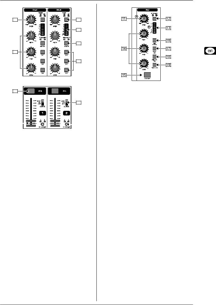
Fig. 2.1: Stereo channel strips
{1} The input select switch lets you switch between two signal sources. Select Line to hear the signal of the Line input [67].
Select Phono/Line to listen to the incoming source signal at the Phono/Line [68] input.
{2} The GAIN knob adjusts the level of the input signal. The actual level is displayed on the level meter {3}.
{3} The 7-segment LED meter indicates the level of the input signal.
{4} Each input channel features a 3-band equalizer (HIGH, MID and LOW) with kill feature, giving you up to 12 dB of boost and a maximum cut of -? dB (kill). The kill feature lets you mute the given frequency range. When each EQ knob is turned fully left, the signal is effectively muted. All EQ parameters can be adjusted in Channel Setup.
{5} The MODE push button changes the functionality of the preset push button {6} from Multi to Single.
{6} The preset push buttons P1, P2 and P3 allow you to store and activate equalizer presets. When activated in Single Mode, these push buttons provide a maximum cut of -? dB (kill function).
{7} Press the PFL push button to listen in on the channel’s signal using headphones.
{8} The fader controls the channel volume.
{9} The CURVE switch adjusts the response of the fader. In
SOFT Mode, the fader responds slower to steady fader movement in the upper range and quicker in the lower range.
In Sharp Mode, the fader adjusts the volume quicker in the upper third and slower in the lower range. In MID Mode, the fader responds in a linear fashion. Since a difference in volume levels is heard when switching between modes, don’t use this switch while playing music!
[10]The CF ASSIGN push button lets you determine on which side of the crossfader [20] (A or B) the signal is to be heard.
Fig. 2.2: Microphone channel
[11]The GAIN knob adjusts the level of the microphone signal at the MIC 1 input.
[12]This switch determines which signal is to be displayed on the level meter [13]. IN VU shows the unprocessed input level which helps you to adjust the microphone signal correctly.
XMC VU shows the level after it has passed the Ultramic processor.
[13]The 7-segment LED meter indicates the level of the microphone channel.
[14]The microphone channel strip features a 3-band equalizer
(HIGH, MID and LOW). The range is +/-12 dB.
[15]The ON/OFF push button turns the microphone channel on and off.
[16]The MIC SETUP push button opens the Mic Setup menu on the display. This allows you to adjust the settings of the equalizer, the Ultramic processor and the MIC FX (effects processor).
[17]The XMC ON push button activates the ULTRAMIC processor, which includes a 2-band compressor and expander.
Ultramic settings can be adjusted in Mic Setup.
[18]The MIC FX ON push button activates the microphone effects processor. Select the effect in Mic Setup.
[19]The TALK ON push button activates the Talkover function. This attenuates the volume level of the music as soon as you speak into the microphone. This is a very useful function to make yourself heard over the music being played. You can adjust all the relevant settings in Talk Setup.
Controls and connections |
7 |

DIGITAL PRO MIXER DDM4000
2.3 Crossfader section
Fig. 2.3: Crossfader section
[20]The replaceable crossfader is used to fade between the signals that are assigned to its two sides A and B. You can assign the stereo channels and sampler using the CF Assign push buttons [10] and [65].
[21]The CF ON push button activates the crossfader. When the push button is not pressed, the signals of the individual channels are routed straight to the Main outputs.
[22]There are 3 Kill push buttons (HIGH, MID and LOW) on each side of the crossfader which let you mute the given frequency range. In Crossfader Setup (see Chapter 3.4.2), it is possible to activate a special X-OVER mode that enhances the crossfader’s functionality in combination with the Kill push buttons. For more information, read Chapter 3.4.1.
[23]Press the FULL FREQ push button to remove any frequency cuts of the KILL EQ [22].
[24]The CURVE knob lets you seamlessly adjust the response of the crossfader.
The REVERSE functionallowsyoutoreversetheconfigurationof the crossfader. This way you can toggle between Channel A and
B at the flick of a switch.
[25]REVERSE HOLD activates a permanent Reverse function. The crossfader fades between sides A and B in the reverse direction. This means that A is now on the right and B on the left side.
[26]REVERSE TAP activates a momentary Reverse function. This means that A and B are interchanged as long as the TAP push button is held down.
The BOUNCE TO MIDI CLOCK function provides an automatic, quick crossfading synchronized to the rhythm of the music
(“bouncing”). The bounce speed is determined by the MIDI Clock.
[27]Press the BOUNCE TO MIDI CLK push button to activate the bouncing. Once the push button is pressed, the signal repeatedly jumps from A to B and back again corresponding to the interval pre-selected by using the BEAT push buttons [28].
[28]The BEAT push buttons let you determine the Bounce rate, which can range between one and 16 beats.
[29]These LEDs indicate the number of beats you have chosen.
++ Find a detailed description of this function in Chapter
3.4.3.
8 |
Controls and connections |
DIGITAL PRO MIXER DDM4000
2.4 Main and Phones section
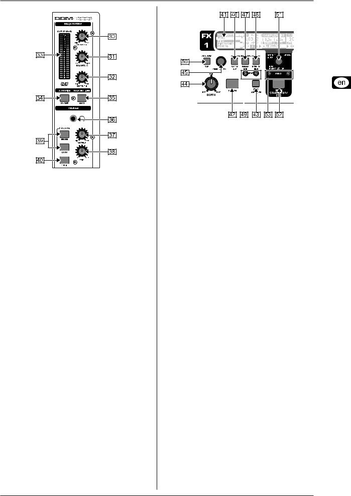
Fig. 2.4: Main and Phones section
MAIN OUTPUT:
[30]The OUTPUT A knob controls the volume of output A
([73]).
[31]The BALANCE knob adjusts the stereo panning of output
A.
[32]The OUTPUT B knob controls the volume of output B
([74]).
[33]The high-resolution, 22-segment OUTPUT LEVEL meter indicates the level of the output signal on OUTPUT A.
[34]ULTRAMIZE ON/OFF push button: The Ultramizer is an effect that enhances the loudness and assertiveness by dynamic compression. In Ultramizer Setup (see Chapter
3.5.1), you can configure the Ultramizer.
[35]The LOAD push button lets you load the user settings of the entire mixer. The settings that are active when the device is turned off are loaded when the device is switched back on again. Read more about saving and loading user settings in Chapter 3.5.2.
PHONES:
[36]Connect the headphones to the PHONES jack (1/4" TRS connector).
[37]The OUTPUT knob controls the volume of the headphones.
[38]The MIX knob adjusts the balance between PFL signal and
PGM signal (PFL = Pre Fader Listening, fader independent pre-listening of individual channels; PGM = Program, Master signal). When the knob is turned completely to the left, you only hear the PFL signal, whereas when turned completely to the right the Master signal is heard. Between these two positions, you can adjust the mix of both signals.
[39]The PUNCH EQ function helps synchronize two tracks. You can orient yourself to the snare or the bass drum or both.
Press the SNARE or BASS push button to emphasize the selected sound in the headphones.
[40]When the SPLIT push button is pressed, the PFL signal is heard in the left headphone and the PGM signal is only heard in the right headphone.
2.5 BPM and Effects section
Fig. 2.5: BPM Counter and Effects section (here FX1)
The DDM4000 has 2 identical effects units. There are 2 additional independent effects units for the mic signal and the Sampler. All effects can be used at the same time. The BPM Counter and MIDI
Clock are also found in this section.
[41]The graphic display shows BPM values, effect names and effect parameters as well as channel assignments. It also leads you through Console Setup.
[42]The FX ON push button activates the effects unit.
[43]Press the FX ASSIGN push button to assign an effects unit to a signal source (push button flashes). The possible input sources are listed on the display. Select the preferred source by turning and pressing the PARAMETER knob [45].
[44]The DEPTH knob adjusts the effect intensity (depth). For some effects, it also lets you adjust the mix between the original signal (dry) and the effect signal (wet).
[45]Press the PARAM(eter) knob to select the effect parameters. By turning the knob, you can change the parameter shown on the display.
[46]Press SELECT/LOW to access the effects list (on the display). Turn and press the knob [45] to load a preset.
[47]Press the PARAM/MID push button to access the effect parameters. Turn the knob [45] to change the parameter value.
[48]Press DEFAULT/HIGH to restore a preset.
++ When the effect is activated (by pressing the FX ON push button), the push buttons [46] (LOW), [47] (MID) and [48] (HIGH) are used as Kill switches in the effect’s signal path.
[49]Depending on the selected effect, the BEAT push buttons can adjusttime-relatedparameters.However,thevaluesentered are not in milliseconds or similar units, but in beats.
[50]To enter the tempo manually, tap this push button (at least 2 x) in the rhythm of the music (TAP). By keeping the AUTO
BPM/TAP push button pressed a little longer (> 1 s), the automatic tempo input (AUTO BPM) is reactivated.
[51]Turn the CONSOLE SETUP knob to adjust the tempo of the MIDI Clock (press and turn simultaneously = coarse adjustment). A short press on the knob confirms the entry made. A long press on the knob lets you access Console
Setup (see Chapter 3.1).
[52]The MIDI START/STOP/ESC turns on the MIDI Clock.
[53]The ADJUST push buttons let you transfer the tempo of the BPM counter to the MIDI Clock.
++ All functions of the BPM and Effects section are described in detail in Chapter 4.
Controls and connections |
9 |
 Loading...