

Page 1
Quick Start Guide
(1)
(2)
(3)
(4)
(5)
(6)
(7)
(8)
(9)
(10) (11) (12) (13) (14) (15)
(17)
(16)
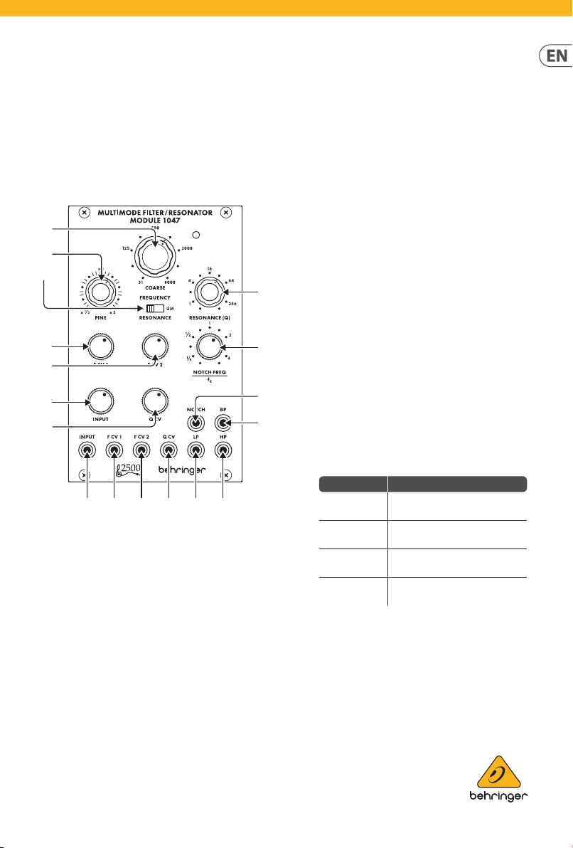
MULTIMODE FILTER /
RESONATOR MODULE 1047
Legendary 2500 Series 12dB State
Variable Filter Module for Eurorack
Controls
(1) COARSE – Use thi s knob to dial in the gene ral frequenc y
area you want f or the high-pas s threshold, low-p ass
threshold, band-pass center frequency and notch lter
center fr equency, then go to the FI NE knob to rene the
freque ncy setting . The frequenc y set by the COARSE and
FINE knobs (“ fc”) will be use d simultaneousl y for every
lter in the module.
(2 ) FINE – U se this knob to rene a nd focus the fre quency set
by the COARSE FREQ UENCY knob.
(3 ) RESONANCE (NORM/LIM) – This sli ding switch let s
you choos e between norma l resonance mode (NO RM)
and limiti ng mode (LIM), which limit s the height of a
lter’s res onant peak. The LIM s etting prevent s circuit
overload w hen focusing a lte r on a strong harmon ic or
fundamental frequency, especially at high Q settings on
the RESON ANCE (Q) knob. In other sit uations, the LIM
setti ng can result in a ver y low output signal, a nd so the
NORM set ting is usually pre ferred.
(4 ) RESONANCE (Q) – This k nob controls the wi dth/
smoothness and narrowness/sharpness of the lter
curve s. At low Q settings, t he lter curves ar e wider and
smoother, wit h a gentler eec t on the sound (except fo r
the notch l ter, which functio ns most eect ively at low
Q setti ngs). As you increase the Q s etting, the lte r curves
graduall y become narrower an d sharper, which can hel p
you to focu s in on narrow frequ ency bands. At high er Q
setti ngs, the various lt ers can produce r esonant peaks
in the lter c urves that boos t some frequen cies and may
require m oving the RESONANC E (NORM/LIM) switch t o
the LIM setting to prevent overloading the circuit (or the
INPUT atte nuator knob can be tu rned down).
(5 ) F C V 1 – This knob adjust s the strength of t he control
voltage si gnal coming in throu gh the F CV 1 jack.
(6 ) F C V 2 – This knob adjust s the strength of t he control
voltage si gnal coming in throu gh the F CV 2 jack.
(7 ) NOTC H FEQUENCY/fc – Use this kno b to oset the notc h
lter’s cente r frequency (“ fc”) set by the COARS E and FINE
frequency controls. For standard notch lter behavior, the
NOTCH FREQ/ fc control should b e set to “1” on the scale.
This stan dard setting c an then be tweaked by m oving the
NOTCH FREQ/ fc knob very sligh tly around “1”. Also, if
higher Q val ues are added via the R ESONANCE knob whi le
the notch l ter is oset fro m fc, the higher Q value s result
in a resona nt peak at fc, with the n otch at the point set by
the NOTCH FREQ /fc knob.
Knob Setting Eect
Full CCW
CCW to 1/4
CW to 4
Full CW
(8 ) INPUT – Th is knob adjusts th e strength of the a udio signal
coming thr ough the INPUT jack.
(9) Q CV – This k nob adjusts the s trength of the Q cont rol
voltage si gnal coming in throu gh the Q CV jack.
(10) INPUT – Use this jac k to route audio signal s into the
module via c ables with 3.5 mm con nectors. You can als o
route in a key board gate signal to “rin g” the lter and
produce a un ique percussive s ound when you press a ke y.
Notch lter output becomes a
copy of the high-pass output
Notch frequency shifts
signicantly below fc
Notch frequency shifts
signicantly above fc
Notch lter output becomes a
copy of the low-pass lter output
V 1.0
Page 2
LOWPASS RESPONSE
16 Hz
16 Hz
16 KHz
BANDPASS RESPONSE
16 Hz
16 Hz 16 KHzFc
HIGHPASS RESPONSE
2 MULTIMOD E FILTER / RESONATOR MODULE 1047
(11) F CV 1 – Use thi s jack to route exte rnal control volt age or
(12 ) F CV 2 – Use this jac k to route exter nal control voltag e or
(13 ) Q CV – Use this j ack to route exter nal control volt age
(14) LP – This jack send s out the nal signal f rom the low-pass
(15) HP – This jack se nds out the nal signa l from the high-
(16) NOTCH – This jack s ends out the nal sign al from the
(17) BP – This jack se nds out the nal signa l from the band-
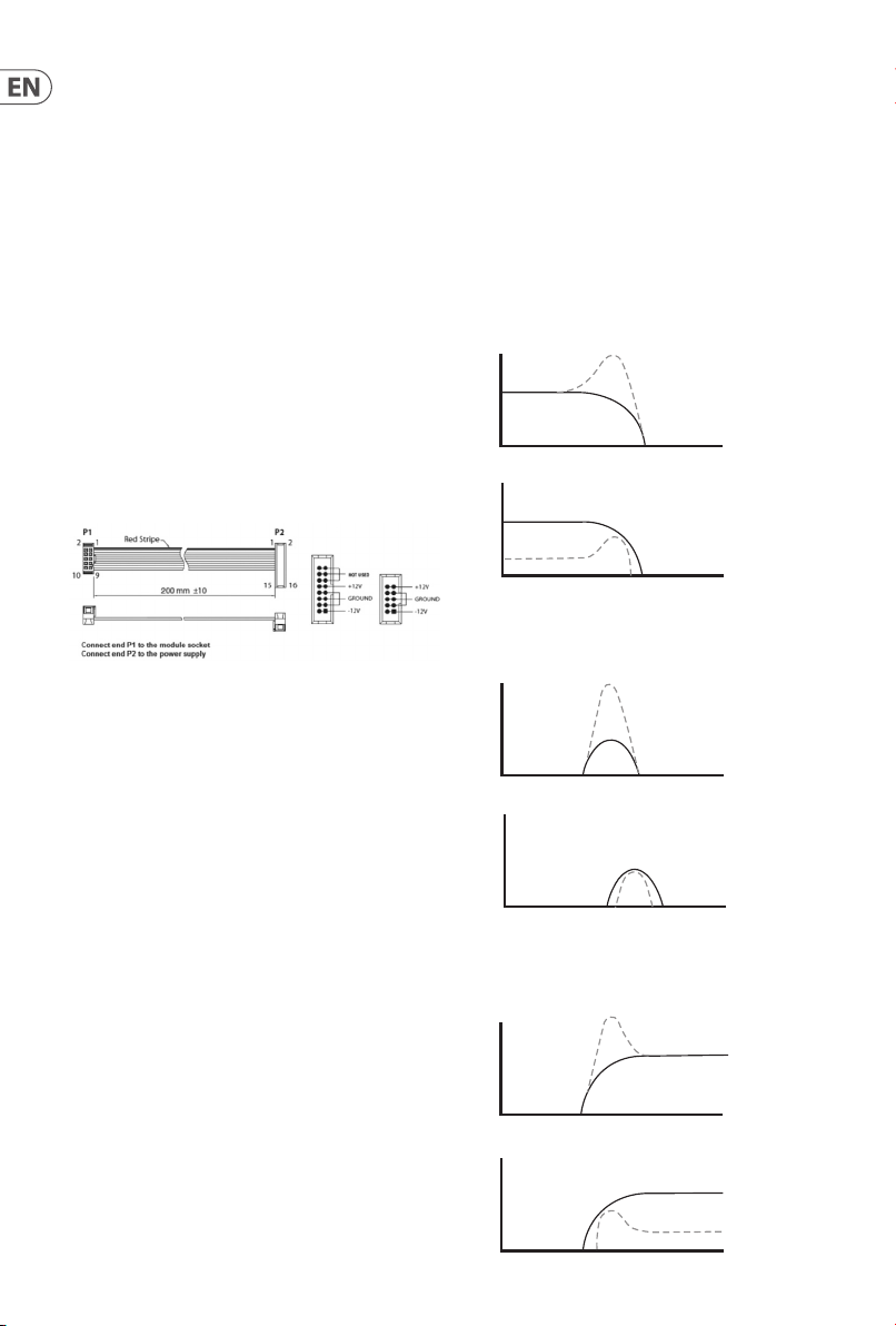
Power Connection
The MULTIMODE FILTER / RE SONATOR MODULE 1047 module
comes wit h the required powe r cable for connec ting to a standar d
Eurorac k power supply syst em. Follow these st eps to connect
power to the mo dule. It is easier to make t hese connecti ons before
the modul e has been mounted int o a rack case.
1. Turn the power supp ly or rack case power o and
2. Ins ert the 16-pin conn ector on the power c able into the
3. Ins ert the 10-pin co nnector into the s ocket on the back of
4. Af ter both ends of the po wer cable have been se curely
Installation
modulation signals for the lter frequency setting into the
module via c ables with 3.5 mm con nectors.
modulation signals for the lter frequency setting into the
module via c ables with 3.5 mm con nectors.
signals fo r the RESONANCE (Q) set ting into the modu le via
cables w ith 3.5 mm connecto rs.
lter via c ables with 3.5 mm conne ctors.
pass lter v ia cables with 3.5 mm c onnectors.
notch lter v ia cables with 3.5 mm c onnectors.
pass lter v ia cables with 3.5 mm c onnectors.
disconne ct the power cabl e.
socket on t he power supply or rac k case. The connec tor has
a tab that wi ll align with the gap in t he socket, so it can not
be inser ted incorrec tly. If the power supply d oes not have
a keyed socke t, be sure to orient pi n 1 (-12 V) with the red
stripe o n the cable.
the modul e. The connector ha s a tab that will align wi th the
socket for correct orientation.
attac hed, you may mount the mo dule in a case and tur n on
the power supply.
The free -moving threa ded plates allow pre cise position ing of the
module, bu t each plate should be p ositioned in th e approximate
relation to the mounting holes in your module before attaching
the screws.
Hold the mo dule against the Eu rorack rails so th at each of the
mounting h oles are aligned w ith a threaded rai l or threaded
plate. Att ach the screws pa rt way to star t, which will allow sma ll
adjustments to the positioning while you get them all aligned. After
the nal pos ition has been es tablished, tig hten the screws do wn.
Filter Curves
Q=2
NORMAL MODE
Q=½
16 KHzFc
Q=½
LIMIT MODE
Q=2
16 KHzFc
Q=½
NORMAL MODE
Q=½
LIMIT MODE
Q=2
Fc
NORMAL MODE
Q=½
16 KHzFc
Q=2
16 Hz 16 KHzFc
16 Hz
Q=2
The neces sary screws a re included wit h the module for mou nting in
a Eurorac k case. Connect t he power cable bef ore mounting.
Dependi ng on the rack case, t here may be a series o f xed holes
spaced 2 HP ap art along the len gth of the case, or a t rack that allows
individ ual threaded plate s to slide along the len gth of the case.
LIMIT MODE Q=½
Q=2
Page 3

Fc/4 4FcFc
NOTCH FREQ
Fc/4 4FcFc
NOTCH FREQ
Fc/4 4FcFc
NOTCH FREQ
3Quick Start Guide
Notch Responses
Fc
Q=½ Q=½
= ¼
Q=2
Fc
Q=2
Q=2
Specications
Inputs
Input
Type 1 x 3.5 mm TS jack, DC coupled
Impedance 50 kΩ, unbalanced
Max input level +18 dBu
Frequency CV input 1
= 1
= 4
Fc
Type 1 x 3.5 mm TS jack, DC coupled
Impedance 50 kΩ, unbalanced
Max input level ±10 V
CV scaling 1 V/oct.
Frequency CV input 2
Type 1 x 3.5 mm TS jack, DC coupled
Impedance 50 kΩ, unbalanced
Max input level ±10 V
CV scaling 1 V/oct.
Q CV input
Type 1 x 3.5 mm TS jack, DC coupled
Impedance 50 kΩ, unbalanced
Max input level ±10 V
CV scaling 1 V doubles the Q factor
Outputs
Filter outputs (LP / HP / BP / Notch)
Type 4 x 3.5 mm TS jack, DC coupled
Impedance 1 kΩ, unbalanced
Max output level +18 dBu
Controls
Coarse frequency 1 x rotary knob, 31 Hz to 8 kHz
Fine frequency 1 x rotary knob, x1/2 to x2
Resonance (Q) 1 rotary knob, Q = 0.5 to >256
Resonance (Norm / lim)
2-way sliding switch
Normal / limiting, switchable
Frequency CV 1 / 2 attenuators 2 x rotary knob, -∞ to unity gain
Q CV attenuator 1 x rotary knob, -∞ to unity gain
Input attenuator 1 x rotary knob, -∞ to unity gain
Notch frequency/fc 1 x rotary knob, ±3 octave range
Power
Power supply Eurorack
Current draw 55 mA (+12 V), 45 mA (-12 V)
Physical
Dimensions 43 x 81 x 129 mm (1.7 x 3.2 x 5.1")
Rack units 16 HP
Weight 0.17 kg (0.37 lbs)
Page 4

4 MULTIMOD E FILTER / RESONATOR MODULE 1047
LEGAL DISCLAIMER
Music Tribe accepts no liability for any loss which may be suered by any person who relies either wholly or in part upon any description, photograph,
or statement contained herein. Technical specications, appearances and other information are subject to change without notice. All trademarks are the property
of their respective owners. Midas, Klark Teknik, Lab Gruppen, Lake, Tannoy, Turbosound, TC Electronic, TC Helicon, Behringer, Bugera, Auratone and Coolaudio are
trademarks or registered trademarks of Music Tribe Global Brands Ltd. © Music Tribe Global Brands Ltd. 2020 All rights reserved.
LIMITED WARRANTY
For the applicable warranty terms and conditions and additional information regarding Music Tribe’s Limited Warranty, please see complete details online at
musictribe.com/warranty.
 Loading...