

Page 1

RS485
Bus coupler BC8000
Version: 2.3
Last change: 2006-11-06
Page 2

Contents
Contents
1. Foreword 3
Notes on the documentation 3
Liability Conditions 3
Delivery conditions 3
Copyright 3
Safety Instructions 4
State at Delivery 4
Description of safety symbols 4
2. Basic information 5
Description of the BC8000 5
The Beckhoff bus terminal system 5
The interfaces 7
Power supply 7
Power supply to the power contacts 7
Power contacts 7
RS 485 Connection 9
K-bus contacts 9
Supply isolation 9
The operating modes of the bus coupler 10
Mechanical construction 11
Technical / PLC Data 13
The peripheral data in the process image 14
Starting operation and diagnostics 16
3. RS485 – Controller BC8000 18
System Introduction 18
Interface Programming 19
The Medium: Plugs and Cables 22
The User Programming Interface 23
Remanent Data 23
Persistent Data 23
4. Appendix 25
Example: Process image in the bus terminal controller 25
Representation of analog signals in the process image 27
Baud Rate Selection Table 28
Read out address 28
Programming Example 29
BC8000 as a Slave 31
General Information 31
TwinCAT as the Master 31
KS8000 as the Master 31
KS2000 Settings 32
Terminal Mapping 32
Firmware 33
5. Questions and Answers 33
General 33
No communication with the BC8x00 33
Mapping of the digital and the byte-oriented Bus Terminals onto a fixed
address 33
Drop of the digital outputs 33
Index 35
6. Support and Service 36
Beckhoff's branch offices and representatives 36
Beckhoff Headquarters 36
2 BC8000
Page 3

Foreword
Foreword
Notes on the documentation
This description is only intended for the use of trained specialists in control and automation engineering
who are familiar with the applicable national standards. It is essential that the following notes and
explanations are followed when installing and commissioning these components.
Liability Conditions
The responsible staff must ensure that the application or use of the products described satisfy all the
requirements for safety, including all the relevant laws, regulations, guidelines and standards.
The documentation has been prepared with care. The products described are, however, constantly under
development. For that reason the documentation is not in every case checked for consistency with
performance data, standards or other characteristics. None of the statements of this manual represents a
guarantee (Garantie) in the meaning of § 443 BGB of the German Civil Code or a statement about the
contractually expected fitness for a particular purpose in the meaning of § 434 par. 1 sentence 1 BGB. In
the event that it contains technical or editorial errors, we retain the right to make alterations at any time
and without warning. No claims for the modification of products that have already been supplied may be
made on the basis of the data, diagrams and descriptions in this documentation.
Delivery conditions
In addition, the general delivery conditions of the company Beckhoff Automation GmbH apply.
Copyright
©
This documentation is copyrighted. Any reproduction or third party use of this publication, whether in
whole or in part, without the written permission of Beckhoff Automation GmbH, is forbidden.
BC8000 3
Page 4
Foreword
i
Safety Instructions
State at Delivery
All the components are supplied in particular hardware and software configurations appropriate for the
application. Modifications to hardware or software configurations other than those described in the
documentation are not permitted, and nullify the liability of Beckhoff Automation GmbH.
Description of safety symbols
The following safety symbols are used in this documentation. They are intended to alert the reader to the
associated safety instructions..
This symbol is intended to highlight risks for the life or health of personnel.
Danger
This symbol is intended to highlight risks for equipment, materials or the
Attention
environment.
This symbol indicates information that contributes to better understanding.
Note
4 BC8000
Page 5

Basic information
Basic information
Up to 64 bus terminals
each with 2 I/O channels
for any form of signal
Decentralized wiring of the
I/O level
IPC as control unit
Bus couplers for all current
bus systems
Standard C rail assembly
Modularity
BC8000 5
Description of the BC8000
The bus terminal controller BC8000 is a bus coupler with integrated PLC
functionality. The controller is programmed in IEC 1131-3. Up to 64
terminals belonging to the Beckhoff bus terminal system can be connected
to the BC8000. These include analog signal types for current and voltage,
as well as PT100 and thermocouples, in addition to digital input and output
terminals. The serial interface of the bus terminal controller can be used for
connection to additional serial devices.
The Beckhoff bus terminal system
The bus terminal system is the universal connecting link between a
fieldbus system and the sensor/actor level. A unit consists of a bus coupler,
which is the interface to the fieldbus, and up to 64 electronic terminals, of
which the last is an end terminal. Terminals, each with two I/O channels,
are available for any form of technical signal and can be combined as
desired. The various types of terminal are all constructed in the same way,
so that the planning costs are kept extremely low. The height and depth of
the construction are calculated for compact terminal cabinets.
Fieldbus technology makes it possible to use compact control
architectures. The I/O level does not need to be taken right up to the
control unit. Sensors and actors can be connected decentrally with minimal
lengths of cable. You can position the control unit at any convenient
location in the installation. Using an industrial PC as control unit makes it
possible to implement the operating and monitoring element as part of the
control hardware, so the control unit can be located on an operating desk,
control point or similar. The bus terminals constitute the decentralized
input/output level of the control unit in the switch cabinet and its
subordinate terminal cabinets. As well as the sensor/actor level, the power
unit of the equipment is also controlled via the bus system. The bus
terminal replaces a conventional terminal as the cabling level in the switch
cabinet; the switch cabinet can be made smaller.
The Beckhoff bus terminal system combines the advantages of a bus
system with the functionality of compact terminals. Bus terminals can be
used on all current bus systems and serve to reduce the diversity of parts
in the control unit, while behaving like the conventional standard units for
the relevant bus system and supporting the entire range of functionality of
the bus system.
The simple and compact assembly on a standard C rail, and the direct
cabling of actors and sensors without cross connections between the
terminals, serve to standardize the installation, as does the uniformly
designed labeling.
The small size and great flexibility of the bus terminal system mean that
you can use it anywhere that you could use a terminal and use any type of
connection – analog, digital, serial or direct sensors.
The modular construction of the terminal row, using bus terminals with
various functions, limits the number of unused channels to at most one per
function. Two channels to a terminal is the optimum solution for the number
of unused channels and the cost per channel. The possibility of using
power input terminals to provide separate power supplies also helps to
minimize the number of unused channels.
Page 6
Basic information
6
6
End terminal
Potential
contacts
RS485
Supply voltage
Display of channel status
The K-bus
End terminal
Power input terminals
for
Separately powered groups
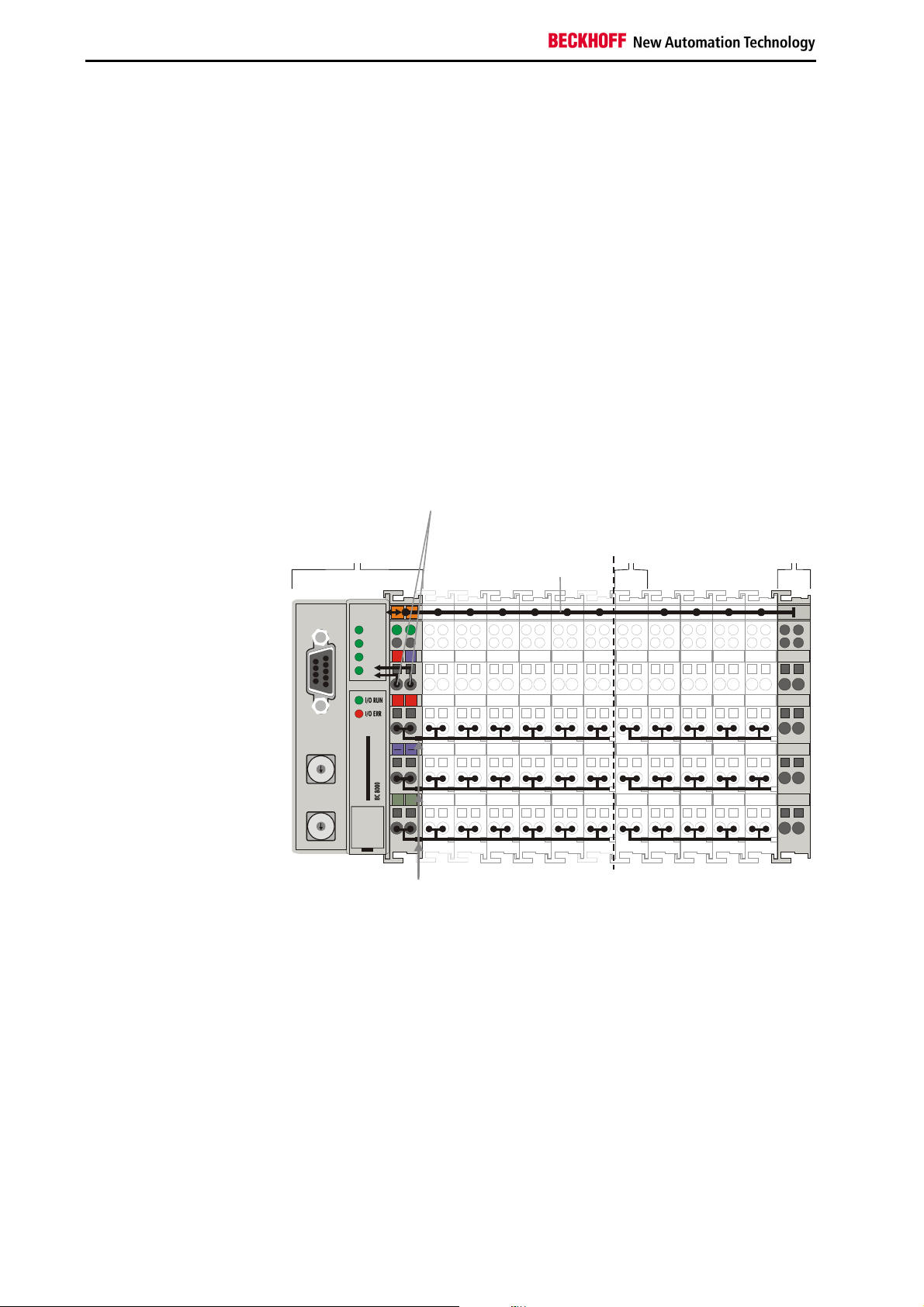
The principle of the bus
terminal
The integrated light-emitting diodes close to the sensor/actor indicate the
status of each channel.
The K-bus is the path taken by data within the terminal row. The bus
coupler carries the K bus through all the terminals by means of six contacts
on the side walls of the terminals, and the end terminal terminates the K
bus. The user does not need to know anything about the function of the K
bus or the internal operation of terminals and bus couplers. There are
numerous software tools available which provide for convenient planning,
configuration and operation.
Three power contacts pass the operating power to the following terminals.
You can use power input terminals to subdivide the terminal row as desired
into groups, each with a separate power supply. These power input
terminals are not taken into account for addressing the terminals, you can
insert them at any position along the terminal row.
You can install up to 64 terminals on a terminal row, including power input
terminals and the end terminal.
bus controller
BC 8000
for the
bus controller
feed
terminal
K bus
Additional characteristics of
the bus terminal controllers
Bus couplers for various
fieldbus systems
RS 485
0
1
9
2
8
3
7
4
5
0
1
9
2
8
3
7
4
5
0201
WD
RX
24V
0V
TX
PLC
+ +
BECKHOFF
PE PE
Power
Galvanic
isolation
Bus terminal controllers (BC) differ from bus couplers (BK) in that, in
addition to K-bus processing, a real-time PLC task is also running. Unlike
bus couplers, the signals from the terminals are processed by the PLC
task, while the fieldbus carries the in- and outputs of the PLC task. It is
possible, however, to subdivide the terminals to that some terminals are
pre-processed by the PLC task, while others are sent directly over the
fieldbus to a supervising system.
Various bus terminal controllers can be used to couple the electronic
terminal strip with integrated PLC task quickly and easily to different
fieldbus systems. It is also possible to convert to another fieldbus system at
a later time. The bus terminal controller performs all the monitoring and
control tasks that are necessary for operation of the connected bus
terminals. The operation and configuration of the bus terminals is carried
out exclusively by the bus terminal controller. Fieldbus, K-bus and I/O level
are galvanically isolated.
6 BC8000
Page 7
Basic information
RS 485
RS 485
Address
If data exchange over the fieldbus fails, the PLC task continues to run as
an autonomous system.
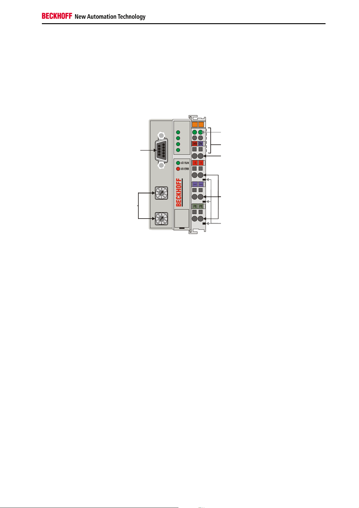
The interfaces
There are six ways of making a connection to a bus coupler. These
interfaces are designed as plug connections and spring terminals.
Serial controller RS485 BC8000
WD
RX
TX
PLC
Power LEDs
bus coupler/power contacts
K bus
Bus coupler power supply 24 V
DC/GND
24 V DC on the topmost
terminals
Lower 3 terminal pairs for
power input
maximum 24 V
maximum 10 A
Power contacts
feeding points
selector
Power contacts
Power supply
The bus couplers need an operating power of 24 V DC which is connected
via the topmost spring terminals, labeled "24 V” and "0 V”. This power
supply serves not only the electronic components of the bus coupler but
(via the K bus) also the bus terminals. The power supply of the bus coupler
circuitry and that of the K-bus (Terminal bus) are electrically isolated from
the voltage of the field level.
Power supply to the power contacts
The six lower connections with spring terminals can be used to supply
power to the peripherals. The spring terminals are connected in pairs to the
power contacts. The power supply to the power contacts has no
connection to the power supply of the bus couplers. The power input is
designed to permit voltages up to 24 V. The pair-wise arrangement and the
electrical connection between the feed terminal contacts makes it possible
to loop through the wires connecting to different terminal points. The load
on the power contact may not continuously exceed 10 A. The current
capacity between two spring terminals is the same as the capacity of the
connecting wires.
Power contacts
Spring contacts at the side
On the right-hand side face of the bus coupler are three spring contacts
which are the power connections. The spring contacts are recessed in slots
to prevent them from being touched. When a bus terminal is connected,
the blade contacts on the left-hand side of the bus terminal are connected
to the spring contacts. The slot and key guides at the top and bottom of the
bus couplers and bus terminals ensure reliable location of the power
contacts.
BC8000 7
Page 8

Basic information
8 BC8000
Page 9
Basic information
Periphery level
Bus terminals
Bus coupler
24 V DC
9 pole Sub-D female
connector strip
RS 485 Connection
There is a recessed front surface on the left-hand side. A 9-pole Sub-D
connector can be plugged in here. A detailed description of the RS485
interface can be found in a further part of this manual (chapter entitled 'The
media: plugs and cable').
K-bus contacts
6 contacts at the side
3 supply groups:
fieldbus
K-bus
peripheral level
Setting up the power levels
in the bus terminal system
The connections between the bus coupler and the bus terminals are
effected by gold contacts at the right-hand side of the bus coupler. When
the bus terminals are plugged together, these gold contacts automatically
complete the connection to the bus terminals. The K bus is responsible for
the power supply to the electronic components of the K bus in the bus
terminals, and for the exchange of data between the bus coupler and the
bus terminals. Part of the data exchange takes place via a ring structure
within the K bus. Disengaging the K bus, for example by pulling on one the
bus terminals, will break this circuit so that data can no longer be
exchanged. However, there are mechanisms in place which enable the bus
coupler to locate the interruption and report it.
Supply isolation
The bus couplers operate with three independent supplies. The input
power supplies the electrically isolated K-bus circuitry in the bus coupler
and the K-bus itself. The power supply is also used to generate the
operating power for the fieldbus.
Note: All the bus terminals are electrically isolated from the K bus, so that
the K-bus is completely electrically isolated.
Terminal bus
BC8000 9
Field bus
Page 10
Basic information
Power on selltest
Bus terminal test
OK
Start-up behaviour of the
bus coupler
The operating modes of the bus coupler
When it is first switched on the bus coupler carries out a self-test to check
the functions of its components and the communications of the K bus, and
while this is going on the red I/O LED will flash. When the self-test has
been completed successfully, the bus coupler will begin to test the
attached bus terminals (the "bus terminal test”) and read in the
configuration from which it constructs an internal structure list, which is not
accessible from outside. If an error occurs the bus coupler will enter the
operating mode "STOP”. If the start-up sequence is completed without
errors the bus coupler will enter the mode "fieldbus start”.
Structure list
Communication start
PLC start/
Stop
The bus coupler reports the error to the master by means of the Profibus
diagnostics. Clearing the error returns the bus coupler to its normal
operating mode.
10 BC8000
Page 11
Basic information
Mechanical construction
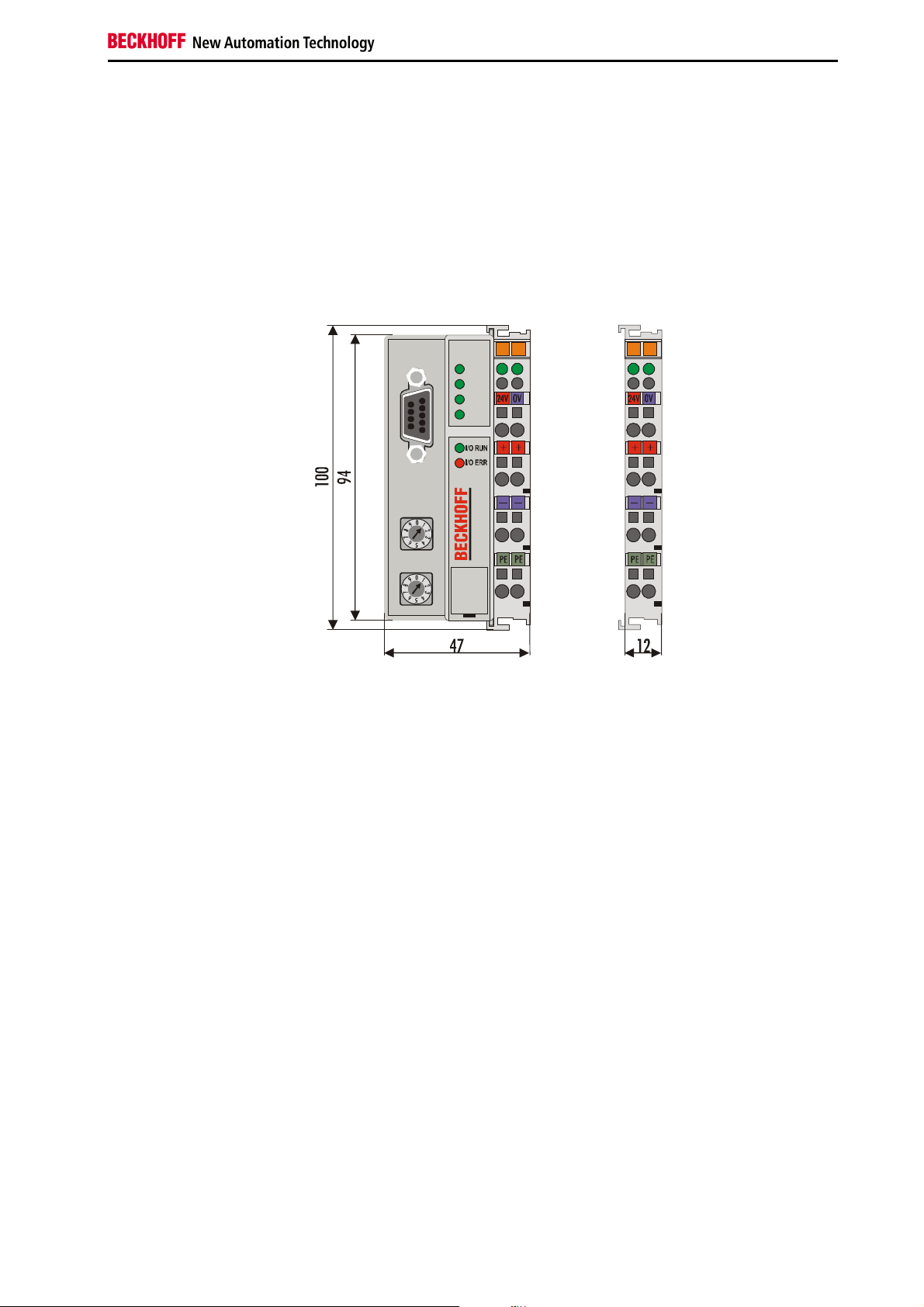
The Beckhoff bus terminal system is remarkable for its compact
construction and high degree of modularity. When you design the
installation you will need to plan for one bus coupler and some number of
bus terminals. The dimensions of the bus couplers do not depend on the
fieldbus system. If you use large plugs, for example like some of the bus
plugs used for the Profibus, they may protrude above the overall height of
the cabinet.
Dimensions of a bus
coupler
RS 485
WD
RX
TX
PLC
The overall width of the construction is the width of the bus coupler,
including the bus end terminal, plus the width of the installed bus terminals.
The bus terminals are 12 mm or 24 mm wide, depending on their function.
Depending on the gauge of cables used the overall height of 68 mm may
be overstepped by about 5 mm to 10 mm by the cables at the front.
Assembly and link
It takes only a slight pressure to latch the bus coupler and the various bus
terminals onto a supporting 35mm C rail and a locking mechanism then
prevents the individual housings from being removed. You can remove
them without effort if you first release the latching mechanism by pulling the
orange tab. You should carry out work on the bus terminals and the bus
coupler only while they are switched off: if you plug or unplug components
while the power is on you may briefly provoke some undefined state (and,
for instance, reset the bus coupler).
You can attach up to 64 bus terminals in series on the right-hand side of
the bus coupler. When you assemble the components, make sure that you
mount the housings so that each slot comes together with the
corresponding key. You cannot make any functional connections merely by
pushing the housings together along the supporting track. When they are
correctly mounted there should be no appreciable gap between the
adjacent housings.
The right-hand side of a bus coupler is mechanically similar to a bus
terminal. There are eight connections on the top which can be used to
connect to thick-wire or thin-wire lines. The connection terminals are spring
loaded. You open a spring terminal by applying a slight pressure with a
screwdriver or other pointed tool in the opening above the terminal and you
can then insert the wire into the terminal without any obstruction. When you
release the pressure the terminal will automatically close and hold the wire
securely and permanently.
BC8000 11
Page 12

Basic information
Insulation test
PE power contacts
The connection between bus couplers and bus terminals is automatically
effected by latching the components together. The K bus is responsible for
passing data and power to the electronic components of the bus terminals.
In the case of digital bus terminals, the field logic receives power via the
power contacts. Latching the components together has the effect that the
series of power contacts constitutes a continuous power track. Please refer
to the circuit diagrams of the bus terminals: some bus terminals do not loop
these power contacts through, or not completely (e.g. analog bus terminals
or 4-channel digital bus terminals). Each power input terminal interrupts the
series of power contacts and constitutes the beginning of a new track. The
bus coupler can also be used to supply power to the power contacts.
The power contact labeled "PE” can be used as protective earth or ground.
This contact stands proud for safety reasons and can carry short-circuit
currents of up to 125A. Note that in the interests of electromagnetic
compatibility the PE contacts are capacitively connected to the supporting
track. This may lead to spurious results and even damage to the terminal
when you test the insulation (e.g. insulation test for breakdown using a
230V mains supply to the PE line). You should therefore disconnect the PE
line on the bus coupler while you carry out insulation tests. You can
disconnect other power supply points for the duration of the test by drawing
the power supply terminals out from the remaining row of terminals by at
least 10mm. If you do this, there will be no need to disconnect the PE
connections.
The protective earth power contact ("PE”) may not be used for any other
connections.
12 BC8000
Page 13

Basic information
Technical / PLC Data
The electrical data of the RS485 bus terminal controller are presented in
this chapter. The bus terminal controller is set to 19,200 baud data rate.
Addresses from 0 to 99 are selectable via two address selectors on the
coupler. The following table gives an overview of all the data:
Technical data BC8000
Number of bus terminals
Digital
peripheral signals
Analogue peripheral signals
Peripheral bytes
Electrical power supply
Input current
Power-on surge
K-bus output current
Connector
Voltage of the power contact
Power contacts current
drawn
Voltage stability
Typical weight
Operating temperature
Storage temperature
Relative humidity
Vibration/shock stability
EMC immunity, burst / ESD
Installation location
Protection class
PLC data
Programmability
Program size
Program memory
Data storage
Remanent flags
Runtime system
PLC cycle time
Programming languages
Station addresses
Interface
Baud rate
64
256 inputs and outputs
128 inputs and outputs
512 inputs and 512 outputs
24 V (- 15% / +20%) EN 61131
70 mA + (total K bus current)/4
500 mA max.
2.5 x steady operating current
1750 mA max.
1 x D-sub plug, 9-pin
24 V DC / AC
10 A
500 Veff (power contact / supply voltage)
170 g
0°C ... +55°C
-25°C ... +85°C
95% without dew formation
according to IEC 68-2-6 / IEC 68-2-27
according to EN 61000-4-4 / EN 61000-4-2, limit values in accordance with
EN 50082-2
arbitrary
IP20
via programming interface or RS485 interface (TwinCAT BC/TwinCAT)
approx. 3000 PLC statements
32 kbytes / 96 kbytes
32 kbytes / 64 kbytes
512 bytes
1 PLC task
approx. 3 ms for 1000 instructions (including K-bus I/O cycle)
IL, LD, FBD, SFC, ST
Selectable to 99 via DIP switch
0: reserved
1 – 98: programming mode
99: interface available for the PLC program
RS485
19,200 baud, 8 data bits, even parity, one stop bit
Current consumption on the
K-bus
For operation of the K-bus electronics, the bus terminals require energy
from the K-bus that is supplied by the bus coupler. Refer to the catalog or
the corresponding data sheets of the bus terminals for details of the K-bus
current consumption. In doing so, pay attention to the maximum output
current of the bus coupler that is available for powering the bus terminals.
Using a special power supply terminal (KL9400), power can be fed back
into the K-bus at any chosen point. If you wish to use a power supply
terminal, please contact Beckhoff’s technical support.
BC8000 13
Page 14

Basic information
The peripheral data in the process image
When the bus coupler is first switched on it determines the configuration of
the attached input/output terminals and automatically assigns the physical
slots of the input/output channels to the addresses in the process image.
The bus coupler sets up an internal list of assignments in which each of the
input and output channels has a specific position in the process image. A
distinction is made here between input and output and between bit-oriented
(digital) and byte-oriented (analog, or complex) signal processing.
It also forms two groups, whereby one contains only inputs and the other
only outputs. In each group, the byte-oriented channels take the lowest
addresses, in ascending order, and these are then followed by the bitoriented channels.
Digital signals
(bit-oriented)
Digital signals are bit-oriented. This means that one bit of the process
image is assigned to each digital channel. The bus coupler sets up a block
of memory containing the current input bits and arranges to immediately
write out the bits from a second block of memory which belongs to the
output channels.
The precise assignment of the input and output channels to the process
image of the control unit is explained in detail in the Appendix by means of
an example.
Analog signals
(byte-oriented)
The processing of analog signals is always byte-oriented and analog input
and output values are stored in memory in a two-byte representation. The
values are held as "SIGNED INTEGER” or "twos-complement”. The digit
"0” represents the input/output value "0V”, "0mA” or "4mA”. When you use
the default settings, the maximum value of the input/output value is given
by "7FFF” hex. Negative input/output values, such as -10V, are
represented as "8000” hex and intermediate values are correspondingly
proportional to one another. The full range of 15-bit resolution is not
realized at every input/output level. If you have an actual resolution of 12
bits, the remaining three bits have no effect on output and are read as "0”
on input. Each channel also possesses a control and status byte in the
lowest value byte. If the control/status byte is mapped in the control unit
has to be configured in the master configuration software. An analog
channel is represented by 2 bytes user data in the process image.
Word alignment
In assigning peripheral signals to the process image of the PLC task and to
the fieldbus process image (depending on fieldbus), the analog and special
signals are mapped with word alignment.
Special signals and
interface
A bus coupler supports bus terminals with additional interfaces, such as
RS232, RS485, incremental encoder, etc.. These signals can be regarded
in the same way as the analog signals described above. A 16-bit data
width may not be sufficient for all such special signals; the bus coupler can
support any data width.
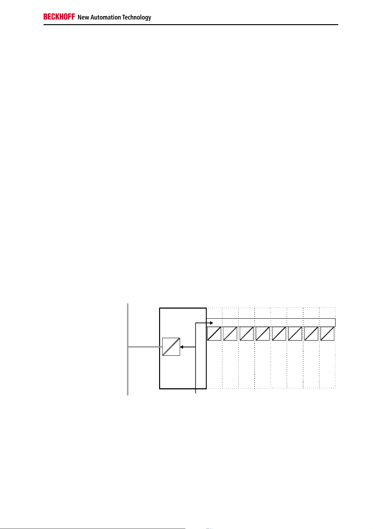
Default assignment of
inputs and outputs to the
process image
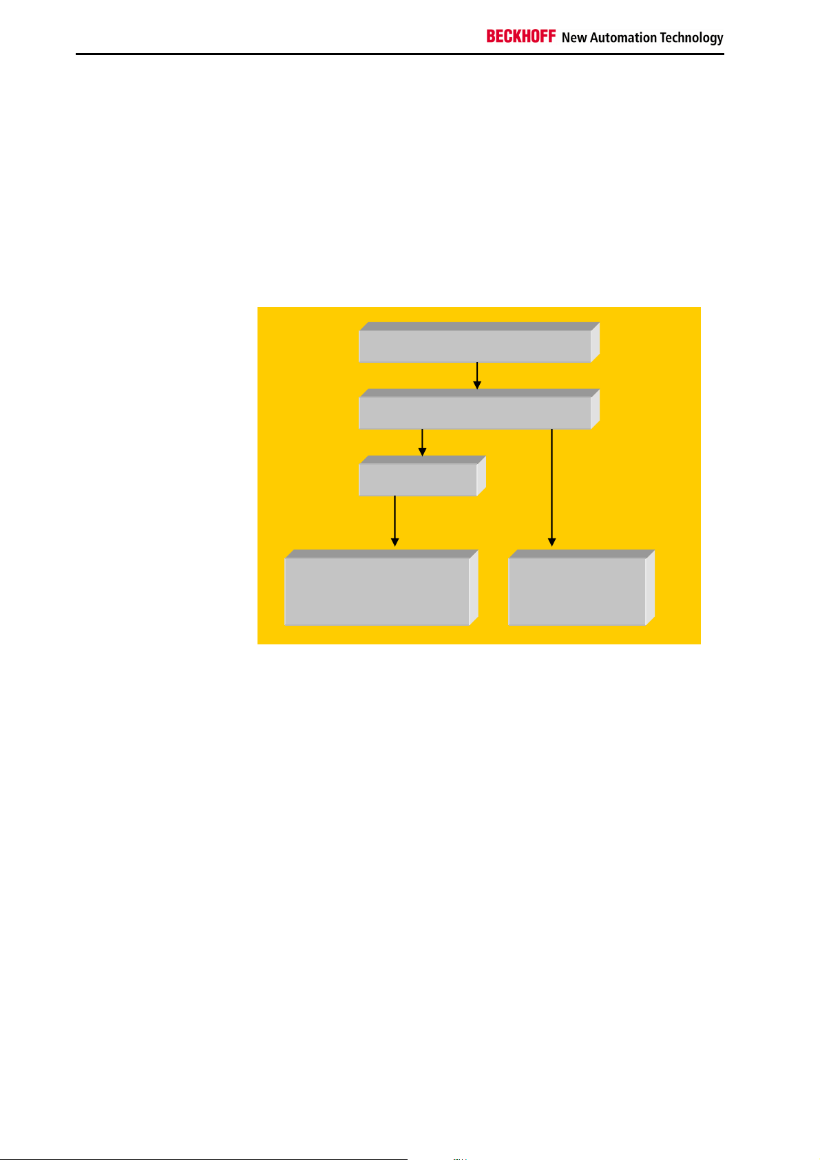
When the bus coupler is first switched on it determines the number of
attached bus terminals and sets up a list of assignments. This list
distinguishes between analog channels and digital channels and between
input and output; which are grouped separately. The assignments begin
immediately to the left of the bus coupler. The software in the bus coupler
creates the assignment list by collecting the entries for the individual
channels one at a time, counting from left to right. These assignments
distinguish four groups:
14 BC8000
Page 15

Basic information
Function type of the channel Assignment level
1.
2.
3.
4
Analog outputs byte-wise assignment
Digital outputs bit-wise assignment
Analog inputs byte-wise assignment
Digital inputs bit-wise assignment
Analog inputs/ouputs are representative of other complex multi-byte signal
bus terminals (RS485, SSI sensor interface, ...)
Overview of the subdivision of the process image in the bus coupler:
Output data in the bus
coupler
O0
...
byte-oriented data
...
Ox
Ox+1
bit-oriented data
Ox+y
Input data in the bus
coupler
I0
...
byte-oriented data
...
Ix
Ix+1
...
bit-oriented data
...
Ix+y
The way from I/Os to the
process image in the
application software
The bus coupler automatically assigns the I/Os of the terminals to the
process image in the RS485 communication protocol. These allocations
can be modified with the Beckhoff KS2000 configuration software. Various
mapping parameters (e.g. Motorola/Intel format) can be set in the bus
coupler.
Processing complex signals
Data which contains no contradictions is said to be consistent. The
following consistency is required here: 1. The high byte and low byte of an
analog value (word consistency), 2. The control/status byte and the
corresponding parameter word for accessing the register. The interaction
of the peripherals with the control unit means that data can initially be
guaranteed consistent only within an individual byte: the bits which make
up a byte are read in together, or written out together. Byte-wise
consistency is quite adequate for processing digital signals but is not
sufficient for transferring values longer than eight bits, such as analog
values. The various bus systems guarantee consistency to the required
length. It is important to use the appropriate procedure for importing this
consistent data from the master bus system to the control unit. The
protocol for communication with the BC8000 always exchanges the
coupler's complete process image, thus ensuring data consistency.
Processing complex signals
All byte-oriented signal channels such as RS232, RS485 and incremental
encoder, can use byte lengths greater than two. Apart from the actual
difference in length, the procedure is always comparable with that for
analog signals
BC8000 15
Page 16

Basic information
Starting operation and diagnostics
When the bus coupler is first switched on it at once checks the attached
configuration. A correct start-up procedure is indicated by the red LED "I/O
ERR” going out. If this LED flashes, this indicates a fault somewhere in the
terminals. You can determine the actual error code by observing the speed
of flashing and number of flashes. This will enable you to clear the fault
quickly.
The diagnostic LEDs
The bus coupler has two groups of LEDs to provide a status display. The
top group of 4 LEDs indicates the status of the respective field bus. In the
case of the BC8000, various data transfer communication states are
displayed.
There are two further green LEDs on the top right side of the bus coupler to
display the supply voltage. The left LED displays the bus coupler's 24 V
power supply. The right LED signals the power supply to the Power
contacts.
Local errors
Two LEDs, the "I/O LEDs”, which are situated below the fieldbus status
LEDs described above, are used to display the operating mode of the bus
terminals and the connection to these bus terminals. The green LED lights
up to indicate error-free operation, where "error-free” implies that
communication with the fieldbus system is also operating correctly. The red
LED flashes at two different rates to indicate a fault, whereby the specific
error is encoded in the pattern of flashes, as follows.
Flashing code
Fast flashing
First slow sequence
Second slow sequence
Start of the error code
Error code
Error argument
Error code Error argument Description
1 pulse
2 pulses
3 pulses
4 pulses
5 pulses
7 pulses
9 pulses
0
1
2
0
n (n > 0)
0 Terminal bus command error
0
n
n Terminal bus error during register
0 PLC time to long
0
n (n>0)
EEPROM checksum error
In line code buffer overflow
Unknown data type
Programmed configuration
Invalid table entry/bus coupler
Invalid table comparison (terminal n)
Terminal bus data error
Breakage after terminal n (0: coupler)
communication with terminal n
Checksum error in program flash memory
Terminal n is not consistent with the
configuration that existed at boot image
entry
The number of pulses (n) indicates the position of the last bus terminal
before the error. Passive bus terminals such as an infeed terminal, for
example, are not counted.
In the case of some errors, the bus coupler does not end the flashing
sequence when the error is remedied. The bus coupler's operating state
remains 'Stop'. The bus coupler can only be restarted by switching the
supply voltage off and on or by means of a software reset. It is only
permitted to remove and to plug in bus terminals in the network after
deactivation. The electronic circuitry of the bus terminals and of the bus
coupler is largely protected against destruction, but malfunctions and
16 BC8000
Page 17

WD
RX
TX
damage cannot be ruled out when devices are plugged together while live.
The occurrence of an error during ongoing operation does not immediately
trigger output of the error code via the LEDs. The bus coupler must be
requested to diagnose the bus terminals. The diagnostic request is
generated after switching on or at the request of the master.
Communication errors
The top four LEDs show the operating states of RS485 communication.
The two bottom LEDs indicate local communication between the bus
coupler and bus terminals (as explained above).
The I/O RUN LED is controlled by the PLC in the synchronous state. The 3
communications LEDs indicate the state of the RS485 transmission. The
operating conditions are indicated by the „WD,“ „RX“ and „TX“ LEDs.
PLC-RUN
The green PLC LED on the bus terminal controller lights up when the PLC
task is in the RUN mode.
RS485
PLC
LED
WD
RX
TX
PLC
blinks,
flickers
blinks,
flickers
lights up,
blinks
Operating state
off Controller operating as master.
The bus terminal controller is receiving data via the
interface.
The bus terminal controller is sending data over the
serial interface.
PLC task is in RUN mode
Creating boot image
The green I/O LED lights up in connection with access to the internal K
bus. However, the bus coupler queries the configuration of the bus
terminals after switching on and does not exchange any data with the
terminals. That is to say, the red I/O LED goes off after an error-free
startup without the green I/O LED having to light up. Then, the green I/O
LED does not light up until data transfer is commenced (see above).
BC8000 17
Page 18

RS485 – Controller BC8000
RS485
External RS485 device
BC8000
RS485
or programming cable to the configuration port of the BC8000
RS485 – Controller BC8000
General
Address selection 99:
Master operation
System Introduction
The BC8000 bus terminal controller allows assembly of a simple peer-topeer connection based on RS485 transmission. Connection for
programming the RS485 controller is established via the serial port on the
PC.
The controller can be programmed per programming standard IEC 1131-3
using TwinCAT BC or TwinCAT software.
There are two different operating modes for the BC8000. These are
selected via the address selection switches.
RS485 connection
Address selection 1-98:
Programming mode
Address selection
BC8000
An additional, external device is connected to the RS485 port of the
BC8000. It could be a display, barcode scanner, BK8000 or similar device.
RS485 connection
RS485
RS232
PC
BC8000
BC8000
The BC8000 is programmed in this mode. There are two possible
transmission paths:
1. The RS485 interface of the bus terminal controller.
The description of the RS485 interface and of the cable is described in
the chapter „The Medium: Cables and Plugs“.
2. The configuration interface of the bus terminal controller.
A special cable is required (included with TwinCAT BC).
• Address 0:
• Address 1-98:
• Address 99:
Reserved
Programming mode
The interface is available for the PLC program.
Master operating mode of the BC8000.
18 BC8000
Page 19

RS485 – Controller BC8000
If the serial interface on the bus terminal controller is not used for master
mode operation, the following chapter may be skipped.
Interface Programming
As described above, the RS485 interface of the BC8000 cannot be used
simultaneously for programming and for communication with an external
device. Hence as a first step the external device will be connected to a
serial communication terminal KL6001. After programming, this terminal is
removed and a KL6001 terminal emulation can be started. This emulation is
the RS485 interface of the BC8000.
Programming Instructions
In order to simplify the process of programming the interface, a flow
diagram has been prepared to make the sequence clear. To orient you, you
will find portions of this diagram repeated in the margin.
KL6001 operation
For programming a KL6001 is used in order to be able to monitor the
communication with the external serial device. The terminal must be
entered in the controller as standard format and with 5 bytes of user data,
as emulation requires this format. In order to shift the terminal, one may
either use KS2000 software or order a parameterised terminal (Order
designation KL6001-0020). The terminal is situated in the process image of
the controller (e.g. at %QB0 and %IB0 if it is plugged in as the first byteoriented terminal – see appendix).
BC8000 19
Page 20

RS485 – Controller BC8000
RS485
RS485 connection
External RS485 device
BC8000
or programming cable to the configuration port of the BC8000
KL6021-0020
KL6001 emulation
The emulation of the serial interface of the BC8000 behaves like a KL6001
and is therefore programmed in exactly the same way. Further information
can be found in the configuration instructions of the KL6001. Once
programming is successfully completed, the terminal can be removed. It
must be noted that the address of the terminal in the emulation must be
changed (emulation address: %IB500..505 and %QB500..505). The
emulation becomes active as soon as the address selector switch is set to
„99“ and the bus terminal controller is restarted.
Input Output
%IB500 Status byte
%IB501 Data in 0
%IB502 Data in 1
%IB503 Data in 2
%IB504 Data in 3
%IB505 Data in 4
%QB500 Control byte
%QB501 Data out 0
%QB502 Data out 1
%QB503 Data out 2
%QB504 Data out 3
%QB505 Data out 4
The table shows the mapping of the interface emulation of the bus terminal
controller. The KL6001-0020 is exactly the same, but at another address.
The terminal address depends on the socket position and on the other
connected terminals. The example in the appendix should clarify this.
RS485 connection
RS485
RS232
PC
BC8000
Control byte in process
data exchange
The control byte is transmitted from the terminal to the controller. For
setting up data exchange (handshake), the control and the status byte are
used in process data exchange.
20 BC8000
Page 21

RS485 – Controller BC8000
i
MSB
REG=0 OL2 OL1 OL0 0 IR RA TR
Status byte in process data
mode
The status byte is transmitted from the terminal to the controller. It contains
the data required for handshake.
MSB
REG=0 IL2 IL1 IL0 BUF_F IA RR TA
TR/TA:TRANSMITREQUEST/ TRANSMITACCEPTED bits
The handshake for data transmission is provided via this bit. A change of
state in TR causes the data set defined via OL0-OL2 (5 bytes maximum) to
be loaded into the transmission FIFO buffer. The terminal signals execution
of this instruction via TA.
RA/RR:REICEIVEACCEPTED/RECEIVEREQUEST
The terminal notifies the controller via a change of state in RR that the data
set defined in IL0-IL1 is located in D0-D4. The data shift is acknowledged
in the control byte using RA; only then will new data be transmitted by the
terminal to the controller.
IR/IA:
INIT-REQUEST/INITACCEPTED
If IR is high, the terminal initializes. The transmission and reception
functions are disabled, the FIFO pointers are reset and the interface is
initialized with the values in the appropriate registers. The completion of
the initialization is acknowledged by the terminal using IA.
BUF_F:
BUFFER-FULL_Flag
The reception FIFO buffer is full. Data received now will be lost.
Error handling
If a parity, framing or overrun error occurs, the corresponding data is lost in
transmission and will not be loaded into the reception FIFO buffer of the
terminal.
If the buffer is full, incoming data will be ignored.
After programming
If programming is successful, four steps must be followed:
1. The absolute addresses (in the BC8000) of the terminals must be
adjusted (only if the KL6001 is removed – see appendix: “Example:
Process image in the bus terminal controller“).
2. Rewrite the address of the serial terminal for the emulation (%QB500
and %IB500).
3. Create the boot image and shut off the controller.
4. Set the address selector to 99 and restart the controller.
The PLC program of the controller will now send and receive via the
RS485 port (9-pin D-sub socket).
Logging on to the controller is now no longer possible. In order to enable
Note
this again, the address selector switch must be set to an address from 1 to
98 and the controller must then be restarted, that is by turning the power
supply off, then on.
For communication with the KL6001 or the emulation, there is a library
which greatly simplifies the handling of communication (TwinCAT PLC
Serial Communication/ComlibBC5B.lib). There is a programming example
in the appendix.
Data block settings for
RS485 controller interface
(only when address 99 is
active)
Default settings are: 8 data bits, even parity bit, one stop bit, baud rate
19,200 baud.
Allowable settings are given in the appendix:
„Baud Rate Selection Table“
BC8000 21
Page 22

RS485 – Controller BC8000
i
1
5: GND
3: RxD/TxD
PE
When addresses 1..98 are selected the baud rate cannot be set. It is
Note
Setting of station addresses
Address selector
identical to the default value.
Selection of station addresses is carried out using the rotary switches on the
left side of the bus terminal controller. The address is set as decimal
number. The upper rotary switch sets the units value and the low one the
tens value of the address. (Example: station address 18: lower rotary switch
= 1, upper rotary switch = 8). In order for the rotary switch setting to be
stored by the bus terminal controller, a reset of the bus terminal controller
must be carried out (brief interruption of the power supply or software reset).
Address
selector
The Medium: Plugs and Cables
Cable connection is provided by a 9-pin D-sub plug on the left side of the
bus terminal controller. A two-conductor shielded cable can be used in which
the shield is bonded to the signal ground (GND).
8: RxD/TxD
6: 5 V
With the BC8000 bus terminal controllers can connections be developed with
several participants, whereby the maximum length amounts to 1200m.
PC
TxD/RxD (3)
RxD/TxD (8)
BC8000
RxD/TxD (3)
TxD/RxD (8)
22 BC8000
Shield
Page 23

RS485 – Controller BC8000
RxD/TxD (3)
TxD/RxD (8)
5 V (6)
Bus matching resistor
Fundamental
characteristics of physical
data transmission per
RS485
TwinCAT BC
RS485
transmission
Network topology
Medium
Max. cable length
Transmission rate
Plug connector
GND (5)
Line-topology, active bus matching resistor on both
ends
Shielded twisted-conductor cable
1200 m
19.2 kbaud
(selectable only with address 99 active – see table in
appendix)
9-pin D-sub plug
The User Programming Interface
The TwinCAT BC programming system for the bus terminal controller uses
the programming system of TwinCAT PLC. Programs can be loaded into a
bus terminal controller via a programming cable and analyzed there.
The programming system for Beckhoff bus terminal controllers is
manufacturer independent according to IEC1131-3. The PLC programs
can be written in 5 different programming languages (IL, FBD, LD, SFC,
ST). In addition, TwinCAT BC offers extensive debug functionalities
(breakpoint, single step, monitoring,...), which facilitate commissioning.
Remanent Data
Data that is to be retained after the coupler has been switched off are
referred to as remanent data (or retain variables). In the BC8x00 this
includes all the variables in the flags area.
Example: VarM1 AT %MB0: INT;
The default setting 64 bytes to be saved, i.e. from %MB0 to %MB63.
The KS2000 software allows this region to be increased to a maximum of
512 bytes (Table 1, Register 15).
Persistent Data1
The Persistent Data remain intact, even after a new program download and
1
From Firmware B2
BC8000 23
Page 24

a reset. Like the Retain Variables, they are stored in the flags area of the
Bus Terminal Controller.
Example: VarP1 AT %MB0: INT;
The Persistent Data are in the same area as the Retain Variables and also
start at %MB0. You first have to enable Retain Variables in order to
achieve a storage increase through the Persistent Data. By default, no
Persistent Variables are declared.
The Persistent Variable memory area must always be smaller or equal
than that of the Retain Variables.
The KS2000 software allows this area to be increased to a maximum of
512 bytes (Table 1, Register 18).
These data are deleted by a general reset.
24 BC8000
Page 25

Appendix
in the bus
Appendix
With this configuration, the
bus terminal controller sets
up the following assignment
list
Portion for byte-oriented
data
Example: Process image
terminal controller
An example shows the assignment of in- and output channels to the
process image. The sample construction should consist of the following
assembly of bus terminals:
Position Functional groups on the rail
POS00
POS01
POS02
POS03
POS04
POS05
POS06
POS07
POS08
POS09
POS10
POS11
POS12
POS13
POS14
POS15
POS16
POS17
POS18
POS19
POS20
POS21
In the BCXXXX bus terminal controllers, all terminals are always assigned
to the PLC, namely in complex evaluation with word alignment. In an
analogue terminal this means 4 input bytes and 4 output bytes per channel.
Relative byte
address
16..23
24..31
32..39
40..45
Bus terminal controller
Digital inputs, 2 channels
Digital inputs, 2 channels
Digital inputs, 2 channels
Digital inputs, 2 channels
Digital inputs, 2 channels
Digital inputs, 2 channels
Digital outputs, 2 channels
Digital outputs, 2 channels
Digital outputs, 2 channels
Analogue inputs, 2 channels
Analogue outputs, 2 channels
Analogue outputs, 2 channels
Analogue inputs, 2 channels
Power feed terminal
Digital inputs, 2 channels
Digital inputs, 2 channels
Digital inputs, 2 channels
Digital outputs, 2 channels
Analogue outputs, 2 channels
KL6001_0020 standard 5 bytes user data
End terminal
Bit position
0..7
none %IB0..7 %QB0..7 POS10
8..15
none %IB8..15 %QB8..15 POS11
none %IB16..23 %QB16..23 POS12
none %IB24..31 %QB24..31 POS13
none %IB32..39 %QB32..39 POS19
none %IB40..45 %QB40..45 POS20
Controller process
image
Input Output
Position in
the block
BC8000 25
Page 26

Appendix
i
Portion for bit-oriented
data, INPUT
Relative byte
address
Portion for bit-oriented
data, OUTPUT
Relative byte
address
Positions POS14 and POS21 are not relevant to data exchange. They do
not appear in the list. If a byte is not fully utilized, e.g. %QB46, the bus
terminal controller pads the remaining bits of the byte with zeros.
Note
If the KL6001-0020 is removed after successful programming of the
interface, all terminals after address 45 shift 6 bytes downward, that is to
address 40.
The distribution of the process image in the bus terminal controller in
overview:
Output data in the bus
terminal controller
O0
...
byte-oriented data
...
O45
O46.0
bit-oriented data
O46.5
Input data in the bus
terminal controller
I0
...
byte-oriented data
...
I45
I46.0
...
bit-oriented data
...
I48.2
Bit position Controller
process image
46
0 %IB46.0 POS01
46
1 %IB46.1 POS01
46
2 %IB46.2 POS02
46
3 %IB46.3 POS02
46
4 %IB46.4 POS03
46
5 %IB46.5 POS03
46
6 %IB46.6 POS04
47
7 %IB46.7 POS04
47
0 %IB47.0 POS05
47
1 %IB47.1 POS05
47
2 %IB47.2 POS06
47
3 %IB47.3 POS06
47
4 %IB47.4 POS15
47
5 %IB47.5 POS15
47
6 %IB47.6 POS16
47
7 %IB47.7 POS16
48
0 %IB48.0 POS17
48
1 %IB48.1 POS17
Bit position Controller process
image
46
0 %QB46.0 POS07
46
1 %QB46.1 POS07
46
2 %QB46.2 POS08
46
3 %QB46.3 POS08
46
4 %QB46.4 POS18
46
5 %QB46.5 POS18
Position in the
block
Position in the
block
26 BC8000
Page 27

Appendix
15
0
GA
Representation of analog signals in the process image
Every analog channel consists of three input bytes and three output bytes
but, in the standard case, one analog channel only occupies one data word
in the process image. These two bytes represent the value as an unsigned
integer, i.e. 15 bits with a sign. The data format is used independently of
the actual resolution. For example: in the case of the resolution of 12 bits,
the four least significant bits are irrelevant. Using the KS2000 configuration
software, it is possible to insert the third byte into the process image for
any chosen channels. The least significant byte has control and status
functions. Various operating modes can be set with the control byte. The 6
least significant bytes can by used as addressing bits. Addressing serves
to write and read the register set. The register set has 64 registers and
permits setting of various operating parameters, for example selection of a
thermocouple type or representation of the value in a different number
format. For further information, refer to the corresponding documentation of
the terminals.
I/O bytes of an analog
channel in the process
image
Output byte 1 Output byte 0 empty Control byte
Input byte 1 Input byte 0 empty Status byte
Significance of the
control/status bytes
for accessing
the register model
BIT 7 0 = NORMAL MODE, 1 = CONTROL MODE
BIT 6
BIT 5
BIT 4
BIT 3
BIT 2
BIT 1
BIT 0
0 = READ, 1 = WRITE
Register address, MSB
Register address
Register address
Register address
Register address
Register address, LSB
Register set of an
analog channel
63
47
31
16
0 Length Type
User area
OFF SET
IN
Factory settings
SoftwareVers
Type
Secondary process image
The meanings of the registers and of the status bytes are explained in the
bus terminals' corresponding data sheets. The structure of the module is
identical for all bus terminals featuring more extensive signal processing.
BC8000 27
Page 28

Appendix
Baud Rate Selection Table
(selectable only with operation mode 99 active and by using KS2000
software)
From Firmware B1
Table 1
Register Characteristic Default
22
Baud rate
0: 38,400 baud
1: 19,200 baud
2: 9,600 baud
3: 57,600 baud
4: 1,200 baud
5: 2,400 baud
6: 4,800 baud
23
Mode
0: 7 data bits, even parity
1: 7 data bits, odd parity
2: 8 data bits, no parity
3: 8 data bits, even parity
4: 8 data bits, odd parity
24
Stop bits
0: one stop bit
1: two stop bits
1
X
3
X
0
X
From Firmware B2
Table 1
Register Characteristic Default
32
Baud rate
0: 38400 baud
1: 19200 baud
2: 9600 baud
3: 57600 baud
4: 1200 baud
5: 2400 baud
6: 4800 baud
33
Mode
0: 7 data bits, even parity
1: 7 data bits, odd parity
2: 8 data bits, no parity
3: 8 data bits, even parity
4: 8 data bits, odd parity
34
Stop bits
0: one stop bit
1: two stop bits
2
X
2
X
0
X
From Firmware B2
Read out address
Table 1
This enables reading of the currently selected address from the flags area.
Register 14 Bit 10 "1" active address in %MB502
"0" no address Default
28 BC8000
Page 29

Appendix
Local variables in program
MAIN
MAIN program
ComControl
Sending
Programming Example
PROGRAM MAIN
(* Program description *)
(* The BC8000 sends a word of output data every 500ms to a BK8000 *)
(* at that time the low byte is always incremented by one *)
(* The BK8000 then returns a word of input data *)
(* The BC8000 analyzes this, shifts the byte one bit to the left and *)
(* again outputs it on its output terminals. Required hard/software: *)
(* 1 x BC8000,1 x KL1104, 2 x KL2114, 1x 9010, 1 x BK8000, *)
(* 2 x KL1104, 2 x KL2112, 1 x KL9010 *)
(* Communications Lib, serial cable with two D-sub plugs *)
VAR
ComControl : KL6Control5B; (* function bloc for automatic *)
(* communication *)
Receive: ReceiveByte; (* function bloc for receiving data *)
Send: SendByte (* function bloc for sending data *)
Sb: BYTE;
Senden:ARRAY[0..6] OF BYTE;
start: BOOL; (* auxiliary variable set to FALSE for the first cycle *)
i2: USINT;
i3: USINT;
Summe: BYTE; (* checksum *)
Timer1: TON; (* starts transmission every 500 ms*)
Starten: BOOL; (* set TRUE every 500ms until all *)
(* data have been sent *)
J0: UINT;
t1: INT;
byAusgang1:ARRAY[0..20] OF BYTE;
EingWorte: USINT;
END_VAR
IF NOT start THEN (* Initialization of the array for the BK8000 protocol *)
senden[0]:=16#50; (* start marker *)
senden[1]:=16#01; (* number of words to be sent *)
senden[2]:=16#11; (* message ident *)
senden[3]:=16#0B; (* coupler address *)
senden[4]:=16#FF; (* DO *)
senden[5]:=16#FF; (* D1 *)
senden[6]:=16#6B; (* checksum *)
Start:=TRUE;
END_IF
(*++++++++++++++++++++++++++++++++++++++++++++++++++++++*)
(* Handshake with the terminal or terminal emulation *)
ComControl( COMin:=KL6InData ,
COMout:=KL6OutData ,
TxBuffer:=TxBuffer ,
RxBuffer:=RxBuffer );
(*-------------------------------- TRANSMISSION --------------------------------------*)
Timer1(IN:=NOT Timer1.Q,PT:=t#100ms); (* a protocol is transmitted *)
(* every 0.5 seconds *)
IF Timer1.Q THEN
Starten:=TRUE;
END_IF
IF Starten THEN
(*------------------------- calculate CHECKSUM --------------------------------------*)
Summe:=0;
BC8000 29
Page 30

Appendix
Receiving
Global variables
FOR i3:=0 TO 5 DO
Summe:=Summe+ senden[i3];
END_FOR
(*------------------------- TRANSMIT SENDEN ----------------------------------------*)
FOR J0:=0 TO 6 DO
IF J0<4 THEN
Sb := senden[J0]; (* values from the ARRAY *)
ELSIF J0=4 THEN
Sb:=senden[J0]; (* D0 as counter from 0 to 255 *)
ELSIF J0=5 THEN
Sb:= senden[J0]; (* D1 is here &HFF *)
ELSIF J0=6 THEN
sb:=Summe; (* checksum *)
END_IF
Send(SendByte:=Sb , TxBuffer:=TxBuffer );
END_FOR
(*------------------------- COUNTER -----------------------------------------------------*)
i2:=i2+1;
IF i2>255 THEN
i2:=0;
END_IF
senden[4]:=i2;
Starten:=FALSE;
END_IF
(*------------------------RECEPTION-----------------------------------------------*)
REPEAT
Receive(RxBuffer:= RxBuffer);
IF Receive.ByteReceived THEN (* waits until data have arrived *)
byAusgang1[t1]:= Receive.ReceivedByte;
byausgang1[t1];
IF byAusgang1[0]<>16#70 THEN(* If the start marker is not *)
(* recognized, the program exits the loop *)
EXIT;
END_IF
EingWorte:=byAusgang1[1];
t1:=t1+1;
END_IF
UNTIL rxBuffer.count = 0
END_REPEAT
IF (T1>5+2*EingWorte) THEN
T1:=0;
END_IF
byAusgang0:=ROL(ByAusgang1[5],byEingang0);
VAR_GLOBAL
(* Address 500 is the emulation terminal *)
(* where %500=status, %501=D0, %502=D1, %503=D2, *)
(* %504=D3, %505=D4 *)
Kl6InData AT %IB500 : KL6inData5B;
Kl6OutData AT %QB500 : KL6outData5B;
RxBuffer : ComBuffer;
TxBuffer : ComBuffer;
byAusgang0 AT %QB6: BYTE; (* 2 x KL2114 *)
byEingang0 AT %IB6:BYTE; (* 1 x KL1104 *)
END_VAR
30 BC8000
Page 31

Appendix
TwinCAT example
BC8000 as a Slave
General Information
When the BC8000 is used as a slave, all the terminals are assigned to the
bus terminal controller. Data can be exchanged with TwinCAT, or with the
KS8000 software, by way of PLC variables. PLC variables are all the
addressed variables on the BC8000 above address 128. This applies to
the input and output process images. The default setting is for the data to
have a length of 16 bytes. The starting address and the length of the data
can both be changed with the aid of the KS2000 software. It should be
noted here that the highest address that can be set is 511.
TwinCAT as the Master
The serial interface is selected under "Miscellaneous" from the System
Manager. The COM port is to be set, and the parameters set to 19200
baud, "even" parity, "8" databits, "1" stopbit. These parameters are fixed,
and can not be changed.
It is also necessary that the lengths of the input and the output data agree.
A BK8000 is entered into the System Manager, and terminals can be
selected, as shown in the figure below, in order to reach the 16 bytes of
input and output. Four KL3002s yield 16 bytes. Which terminal is used is
not significant, as it can be renamed in the System Manager. What is
important that neither less nor more than 16 bytes are configured.
BC8000 31
KS8000 as the Master
The KS8000 software is the OCX for the serial communication with the
BK8000 and BK8100 bus couplers. This software tool can also be used to
control the BC8000 and the BC8100. The restriction here is that access is
limited to the PLC variables.
The COM port is to be set, and the parameters set to 19200 baud, "even"
parity, "8" databits, "1" stopbit. These parameters are fixed, and can not be
changed.
It is also necessary for the lengths of the input and output data to agree.
The default setting for these is 16 bytes or 8 words of input and output.
Page 32

Appendix
VisualBasic Beispiel
Dim LRet As Long
Dim PlSendBuff(7) As Long
Dim PlRecBuff(7) As Long
Dim RecLen As Long
Dim SendLen As Long
Dim Address As Long
Dim Status As Long
Private Sub cmdButton_Click()
Lret = BKcomOCX1.BK8xProcSyncReadWriteReq(Address, Status,
SendLen, PlSendBuff(0), RecLen, PlRecBuff(0))
LblShow = PlRecBuff(0)
End Sub
Private Sub cmdEnd_Click()
BKcomOCX1.BKxPortOpen = False
End
End Sub
Private Sub Form_Load()
RecLen = 8
SendLen = 8
Address = 11
Status = 1
BKcomOCX1.BKxBaudrate = Baud_19200
BKcomOCX1.BKxCommPort = 2
BKcomOCX1.BKxTyp = BKxType_RS232
BKcomOCX1.BKxPortOpen = True
End Sub
KS2000 Settings
In order to log in via the KS2000 software, the Multipoint address must
correspond with the address of the Bus Terminal Controller.
In order to make changes to the register settings, it is necessary to lift the
write protection in the KS2000 software.
Table 1
Register Description Value range Default
values
0
Offset of the PLC variables inputs 0..511 128
1
Length of the PLC variables inputs 0..511 16
2
Offset of the PLC variables outputs 0..511 128
3
Length of the PLC variables outputs 0..511 16
Terminal Mapping
The precise assignment of the byte-oriented bus terminals may be found in
the appropriate Bus Terminal documentation.
The documentation is available on the product CD or on the Internet under
www.beckhoff.de.
Byte oriented bus terminals Bit oriented bus Terminals
KL1501 KL10XX, KL11XX, KL12XX, KL17XX
KL2502
KL20XX, KL21XX, KL22XX, KL26XX
KL27XX
KL3XXX
KL4XXX
KL5XXX
KL6XXX
KL9110, KL9160, KL9210, KL9260
32 BC8000
Page 33

Questions and Answers
Persistent data, changing of the default values during
Example 3200B2020000
Table
Firmware
The label under the coupler will tell you which firmware is installed in the
Bus Coupler. (Fourth and fifth positions)
The current Firmware version is B2.
To update your firmware you need the KS2000 software and the
appropriate serial cable, supplied along with KS2000. You may find the
firmware under www.Beckhoff.de.
Firmware Description
B1
Released version
B2
emulation
Questions and Answers
Problem
Solution
Problem
Solution
Example
Problem
General
No communication with the BC8x00
After changing the BC8x00 default parameters, you can log in neither with
KS2000 nor with TwinCAT (BC).
It is likely that the interface parameters were changed. Proceed as follows
in order to reload the default parameters:
- Switch off the BC8x00
- Remove all bus terminals and only connect the end terminal
- Set address 99
- Switch the BC8x00 back on
- I/O RUN and ERR flash simultaneously (manufacturer‘s setting active)
You can now continue as usual.
Mapping of the digital and the byte-oriented Bus Terminals
onto a fixed address
You want a constant start address for the digital inputs and outputs.
With the KS2000 software, you can enter an offset start value for the digital
inputs and outputs in table 0. The byte-oriented Bus Terminals should not
jut into this process image, i.e. no overlap should occur.
Table 0:
Register 19 offset for digital outputs
Register 20 offset for digital inputs
"0" is the default setting (automatic Bus Terminal mapping)
You have a KL3002 and a KL2012. In the default case, the KL3002 maps
onto %IB0- %IB7 and %QB0-QB7 in the memory. The digital output
terminal would now map to %QX8.0 and %QX8.1. As soon as you now plug
another byte-oriented Bus Terminal, the process image of the digital Bus
Terminal is moved to a higher memory. You can now pre-empt this by
entering 20 in register 19. This means that KL2012 now maps onto
%QX20.0 and %QX20.1.
Drop of the digital outputs
Your digital outputs drop away.
BC8000 33
Page 34

Questions and Answers
Solution
Recommendation
Your program takes longer than 100 ms. Because the internal K-Bus runs
synchronous with your PLC program, it is no longer triggered early enough,
and the Bus Terminal watchdog becomes active. This can be rectified by
triggering a short refresh of the K-Bus. The setting can be carried out with
the KS2000 software.
Table 1 register 17
LowByte cycle time to K-Bus refresh (<= 80 ms)
HighByte Retries
Enter 0x0350 in table 1, register 17, i.e. three retries, all at 80 ms.
Note that this causes the Bus Terminal watchdog to increase to 240 ms
during a fault condition (this is not true in case of a K-Bus error, where the
watchdog will remain at 100 ms).
34 BC8000
Page 35

Questions and Answers
Index
Address selector 19
Assembly 8
Baud rate 25
Cable length 20
Current consumption on the K-bus 10
Device description 3
Diagnostic LED 13
Error code 13
Interfaces 5
K-bus 4
KS2000 29
KS8000 28
Manufacturer’s setting 30
Mapping of digital Bus Terminals 30, 31
Mechanical construction 8
Number of stations 20
Persistent-Data 20
PIN assignment 19
PLC data 10
PLC LED 14
Power contacts 4, 5, 8
Power supply 5
Process image example 22
Programming Example 26
Read out address 25
Remanent Data 20
RS485 cable 19
Slave 28
Starting operation 13
Technical data 10
TwinCAT 28
Word alignment 11
If you have suggestions to make or ideas about our documentation, please send us an e-mail,
stating the version number, at
Dokumentation@Beckhoff.de.
BC8000 35
Page 36

Support and Service
Support and Service
Beckhoff and their partners around the world offer comprehensive support and service, making available
fast and competent assistance with all questions related to Beckhoff products and system solutions.
Beckhoff's branch offices and representatives
Please contact your Beckhoff branch office or representative for local support and service on Beckhoff
products!
The addresses of Beckhoff's branch offices and representatives round the world can be found on her
internet pages: http://www.beckhoff.com
You will also find further documentation for Beckhoff components there.
Beckhoff Headquarters
Beckhoff Automation GmbH
Eiserstr. 5
33415 Verl
Germany
phone: + 49 (0) 5246/963-0
fax: + 49 (0) 5246/963-198
e-mail: info@beckhoff.com
web: www.beckhoff.com
Beckhoff Support
Support offers you comprehensive technical assistance, helping you no only with the application of
individual Beckhoff products, but also with other, wide-ranging services:
• support
• design, programming and commissioning of complex automation systems
• and extensive training program for Beckhoff system components
hotline: + 49 (0) 5246/963-157
fax: + 49 (0) 5246/963-9157
e-mail: support@beckhoff.com
Beckhoff Service
The Beckhoff Service Center supports you in all matters of after-sales service:
• on-site service
• repair service
•
spare parts servive
• hotline service
hotline: + 49 (0) 5246/963-460
fax: + 49 (0) 5246/963-479
e-mail: service@beckhoff.com
36 BC8000
 Loading...