

Page 1

MODBUS
Bus Terminal Controller
BC7300
Version: 1.5
Last change: 2006-11-06
Page 2

Please note the following
Target group
Safety requirements
The documentation has been prepared with care. The products described
©
This description is only intended for the use of trained specialists in control
and automation engineering who are familiar with the applicable national
standards.
The responsible staff must ensure that the application or use of the
products described satisfy all the requirements for safety, including all the
relevant laws, regulations, guidelines and standards.
are, however, constantly under development. For that reason the
documentation is not in every case checked for consistency with
performance data, standards or other characteristics, and does not
represent an assurance of characteristics in the sense of § 459, Para. 2 of
the German Civil Code. In the event that it contains technical or editorial
errors, we retain the right to make alterations at any time and without
warning. No claims for the modification of products that have already been
supplied may be made on the basis of the data, diagrams and descriptions
in this documentation.
This manual is copyrighted. Any reproduction or third party use of this
protected publication, whether in whole or in part, without the written
permission of Elektro Beckhoff GmbH, is forbidden.
BC7300
Page 3

Table of contents
1. Foreword 5
Notes on the documentation 5
Liability Conditions 5
Delivery conditions 5
Copyright 5
Safety Instructions 6
State at Delivery 6
Description of safety symbols 6
Table of contents
2. Basic Principles 7
Device Description of the BC7300 7
The Beckhoff Bus Terminal System 7
The interfaces 9
Electrical power supply 9
Power contacts feeding points 9
Power contacts 9
Fieldbus connection 9
Configuration and programming interface 10
KS2000 Software 10
TwinCAT BC 10
K-Bus Contacts 10
Electrical isolation 10
Operating Modes of the Bus Terminal Controller 11
Mechanical structure 11
Technical data 14
Peripheral Data in the Process Image 15
Start-up procedure and Diagnostics 16
Fieldbus errors 18
3. MODBUS 19
Basic Principles 19
Bus Topology 19
Process Data and Memory Map 20
MODBUS Process Image 22
BC7300 Process Image 22
Assignment of the Bus Terminals 23
Setting and Parameterisation of the MODBUS 24
Parameterisation Table 25
The MODBUS Protocol 26
ASCII 26
RTU 26
Functions 27
Read Digital Outputs (Function 1) 27
Read Digital Inputs (Function 2) 28
Read Analog In/Outputs (Function 3) 28
Read Analog Inputs (Function 4) 29
Writing a Digital Output (Function 5) 30
Writing an Analog Output (Function 6) 30
Writing a Number of Digital Outputs (Function 15) 31
Writing a Number of Analog Outputs (Function 16) 32
Writing and Reading Analog Outputs and Inputs 33
(Function 23) 33
Echoes a query (Sub-Function 0) 35
Bus Coupler Reset (Sub-Function 1) 35
Delete All Counter Contents (Sub-Function 10) 35
Bus Communication Error Counter (Sub-Function 11) 35
Error Answer Counter (Sub-Function 13) 35
Slave Answers (Sub-Function 14) 36
BC7300 3
Page 4

Table of contents
Unsent Slave Answers (Sub-Function 15) 36
Number of Error Answers (Sub-Function 16) 36
BC7300 Error Answers 37
4. Bus Terminal Controller 38
PLC Cycle Time 38
PLC Variables 38
Remanent Variables 38
Persistent Data 39
Allocated flags area 40
5. Appendix 41
MODBUS Interface 41
Mapping the Bus Terminals 42
List of references 42
Firmware 42
Table 42
Example Program 43
Explanation of the Program 43
The Program in the Bus Terminal Controller 43
Creating the BOOT Program 44
MODBUS Communication 44
6. Questions and Answers 46
General 46
No communication with the BC7300 46
Mapping of the digital and the byte-oriented Bus Terminals onto a fixed
address 46
Drop of the digital outputs 46
7. Index 47
8. Support and Service 48
Support and Service 48
Beckhoff Headquarters 48
Beckhoff's branch offices and representatives 48
4 BC7300
Page 5

Foreword
Foreword
Notes on the documentation
This description is only intended for the use of trained specialists in control and automation engineering
who are familiar with the applicable national standards. It is essential that the following notes and
explanations are followed when installing and commissioning these components.
Liability Conditions
The responsible staff must ensure that the application or use of the products described satisfy all the
requirements for safety, including all the relevant laws, regulations, guidelines and standards.
The documentation has been prepared with care. The products described are, however, constantly under
development. For that reason the documentation is not in every case checked for consistency with
performance data, standards or other characteristics. None of the statements of this manual represents a
guarantee (Garantie) in the meaning of § 443 BGB of the German Civil Code or a statement about the
contractually expected fitness for a particular purpose in the meaning of § 434 par. 1 sentence 1 BGB. In
the event that it contains technical or editorial errors, we retain the right to make alterations at any time
and without warning. No claims for the modification of products that have already been supplied may be
made on the basis of the data, diagrams and descriptions in this documentation.
Delivery conditions
In addition, the general delivery conditions of the company Beckhoff Automation GmbH apply.
Copyright
©
This documentation is copyrighted. Any reproduction or third party use of this publication, whether in
whole or in part, without the written permission of Beckhoff Automation GmbH, is forbidden.
BC7300 5
Page 6
Foreword
i
Safety Instructions
State at Delivery
All the components are supplied in particular hardware and software configurations appropriate for the
application. Modifications to hardware or software configurations other than those described in the
documentation are not permitted, and nullify the liability of Beckhoff Automation GmbH.
Description of safety symbols
The following safety symbols are used in this documentation. They are intended to alert the reader to the
associated safety instructions..
This symbol is intended to highlight risks for the life or health of personnel.
Danger
This symbol is intended to highlight risks for equipment, materials or the
Attention
environment.
This symbol indicates information that contributes to better understanding.
Note
BC7300 6
Page 7

Basic Principles
Up to 64 Bus Terminals
Each having 2 I/O channels
for each signal form
De-centralised wiring of
each I/O level
IPC as controller
Bus Couplers for all usual
bus systems
Standard C - rail assembly
Modularity
Device Description of the BC7300
The BC7300 Bus Terminal Controller is a Bus Coupler with integrated PLC
functionality and a MODBUS slave interface.
The controller is programmed in IEC 1131-3. Up to 64 terminals belonging
to the Beckhoff Bus Terminal System can be connected to the BC7300.
These include analog signal types for current and voltage, as well as
PT100 and thermocouples, in addition to digital input and output terminals.
The Bus Terminal Controller's MODBUS interface allows a MODBUS
master to be connected.
The Beckhoff Bus Terminal System
The Bus Terminal system is the universal interface between a fieldbus
system and the sensor / actuator level. A unit consists of a Bus Coupler as
the head station, and up to 64 electronic series terminals, the last one
being an end terminal. For each technical signal form, terminals are
available each having two I/O channels, and these can be mixed in any
order. All the terminal types have the same mechanical construction, so
that difficulties of planning and design are minimised. The height and depth
match the dimensions of compact terminal boxes.
Fieldbus technology allows more compact forms of controller to be used.
The I/O level does not have to be brought to the controller. The sensors
and actuators can be wired de-centrally, using minimum cable lengths. You
can locate the controller installation anywhere within the plant. The use of
an Industrial PC as the controller means that the operating and observing
element can be implemented in the controller’s hardware. The controller
can therefore be located at an operating panel, in a control room, or at
some similar place. The Bus Terminals form the de-centralised input/output
level of the controller in the control cabinet and the subsidiary terminal
boxes. The power sector of the plant is also controlled over the bus system
in addition to the sensor/actuator level. The Bus Terminal replaces the
conventional series terminal as the wiring level in the control cabinet. The
control cabinet can have smaller dimensions.
The Beckhoff Bus Terminal system unites the advantages of a bus system
with the possibilities of the compact series terminal. Bus Terminals can be
driven within all the usual bus systems, thus reducing the controller parts
count. The Bus Terminals then behave like conventional connections for
that bus system. All the performance features of the particular bus system
are supported.
The easy, space-saving assembly on a standard C-rail, and the direct
wiring of actuators and sensors without cross-connections between the
terminals standardises the installation. The consistent labelling scheme
also contributes.
The small physical size and the great flexibility of the Bus Terminal system
allows it to be used wherever a series terminal is also used. Every type of
connection, such as analog, digital, serial or the direct connection of
sensors can be implemented.
The modular assembly of the terminal strip with Bus Terminals of various
functions limits the number of unused channels to a maximum of one per
function. The presence of two channels in one terminal is the optimum
compromise of unused channels and the cost of each channel. The
possibility of galvanic isolation through potential feed terminals also helps
Basic Principles
BC7300 7
Page 8
Basic Principles
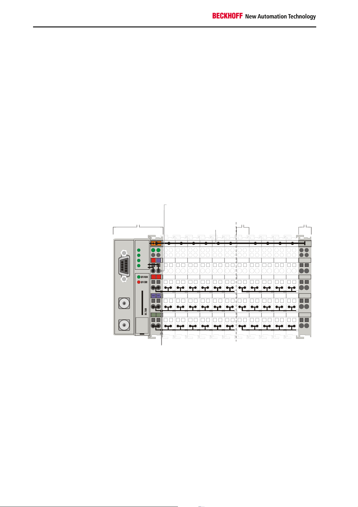
6
6
End Terminal
Potential
contacts
Bus Coupler
Display of the channel state
K-Bus
End terminal
Potential feed terminals for
galvanically isolated groups
The principle of the
Bus Terminal
to keep the number of unused channels low.
The integrated LEDs show the state of each channel at a location close to
the sensors and actuators.
The K-Bus is the data path within a terminal strip. The K-Bus is led
through from the Bus Coupler through all the terminals via six contacts on
the terminals‘ side walls. The end terminal terminates the K-Bus. The user
does not have to learn anything about the function of the K-Bus or about
the internal workings of the terminals and the Bus Coupler. Many software
tools that can be supplied make project planning, configuration and
operation easy.
The operating voltage is passed on to following terminals via three power
contacts. You can divide the terminal strip into arbitrary galvanically
isolated groups by means of potential feed terminals. The feed terminals
play no part in the control of the terminals, and can be inserted at any
points within the terminal strip.
Up to 64 terminals may be located in a terminal strip, including the potential
feed terminals and end terminal.
Bus Coupler
BC7300
power
supply
input
terminal
K-Bus
MODBUS
0
1
9
2
8
3
7
4
5
0
1
9
2
8
3
7
4
5
0201
WD
RX
24V
0V
TX
PLC
+ +
BECKHOFF
PE PE
Power
Potential
isolation
Additional characteristics of
the Bus Terminal
Controllers
Bus Terminal Controllers (BC) differ from Bus Couplers (BK) in that, in
addition to K-Bus processing, a real-time PLC task is also running. Unlike
Bus Couplers, the signals from the terminals are processed by the PLC
task, while the fieldbus carries the in- and outputs of the PLC task. It is
possible, however, to subdivide the Bus Terminals to that some Bus
Terminals are pre-processed by the PLC task, while others are sent
directly over the fieldbus to a supervising system.
Bus Terminal Controllers
for various fieldbus systems
Various Bus Terminal Controllers can be used to couple the electronic
terminal strip with integrated PLC task quickly and easily to different
fieldbus systems. It is also possible to convert to another fieldbus system at
a later time. The Bus Terminal Controller performs all the monitoring and
control tasks that are necessary for operation of the connected Bus
Terminals. The operation and configuration of the Bus Terminals is carried
out exclusively by the Bus Terminal Controller. Fieldbus, K-Bus and I/O
level are galvanically isolated.
BC7300 8
Page 9
02
01
+
+
4
3
2
1
3
2
Power LEDs
Bus Coupler / power contacts
PLC
Basic Principles
If data exchange over the fieldbus fails, the PLC task continues to run as
an autonomous system.
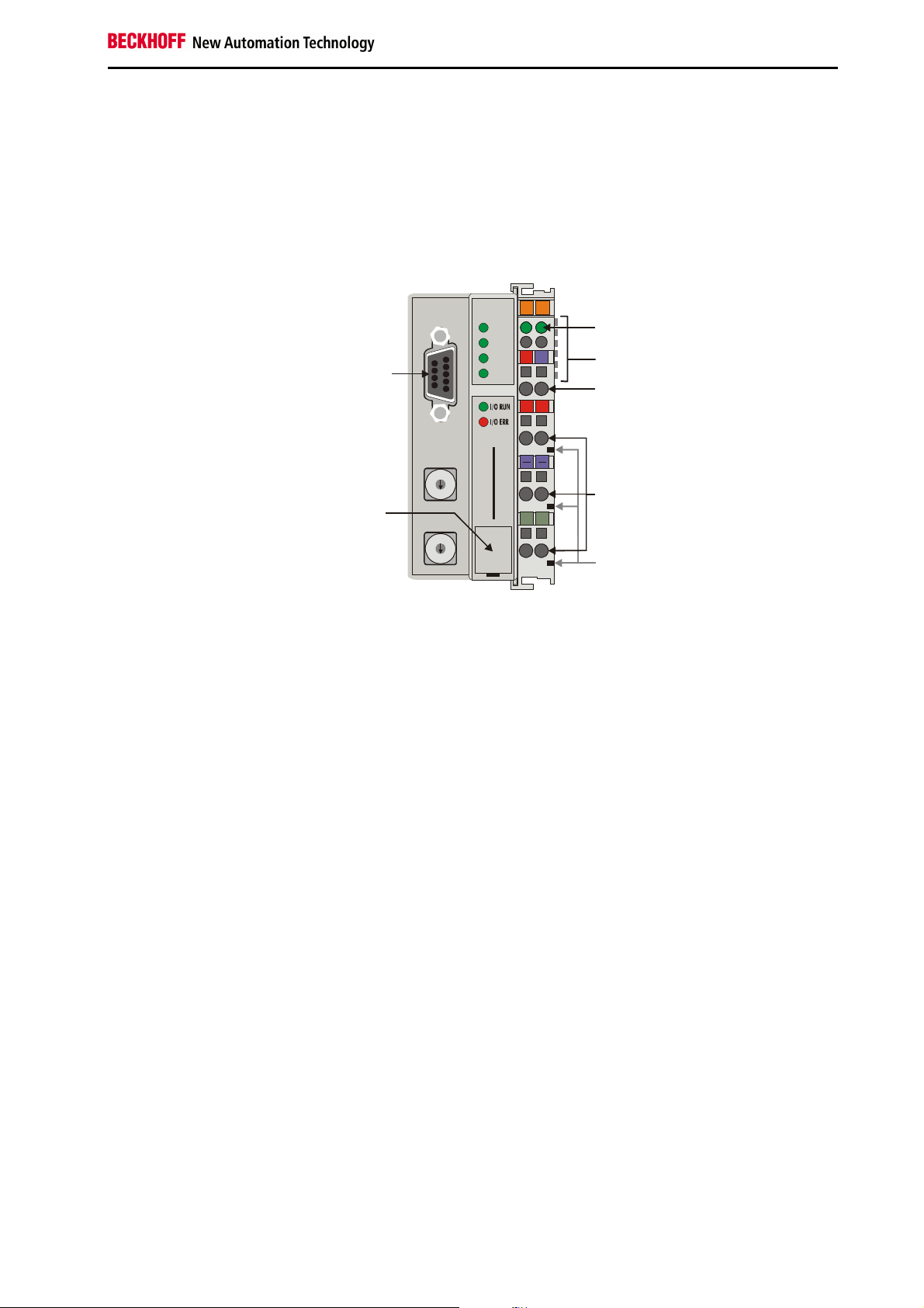
The interfaces
A Bus Terminal Controller has six different methods of connection. These
interfaces are designed as plug connectors and as spring-loaded terminals.
The MODBUS – Bus
Terminal Controller
BC7300
MODBUS
MODBUS
WD
RX
TX
24V
0V
K-Bus
Bus Coupler power supply
24 V DC / GND
0
1
9
Configuration and
programming
interface
8
7
4
6
5
BECKHOFF
BC 7300
PE PE
0
9
8
7
6
5
Power contacts
feeding points
Power contacts
24 V DC to the topmost
terminals “24 V” and “0 V”
Electrical power supply
The Bus Terminal Controllers require a 24 V DC supply for their operation.
The connection is made by means of the upper spring-loaded terminals
labelled “24 V” and “0 V”. This supply voltage feeds not only the Bus
Coupler electronics via the K-Bus, but also the Bus Terminals. The power
supply for the Bus Coupler electronics and that of the K-Bus are electrically
separated from the potential of the field level.
Lower 3 terminal pairs for
power feed
Maximum 24 V
Maximum 10 A
Power contacts feeding points
The bottom six connections with spring-loaded terminals can be used to
feed the supply for the peripherals. The spring-loaded terminals are joined
in pairs to a power contact. The feed for the power contacts has no
connection to the voltage supply for the Bus Coupler. The design of the
feed permits voltages of up to 24 V. The assignment in pairs and the
electrical connection between feed terminal contacts allows the connection
wires to be looped through to various terminal points. The current drawn
from the power contact must not exceed 10 A for long periods. The current
rating between two spring-loaded terminals is identical to that of the
connecting wires.
Spring contacts on the side
Power contacts
On the right hand face of the Bus Terminal Controller there are three spring
contacts for the power contact connections. The spring contacts are hidden
in slots so that they can not be accidentally touched. By attaching a Bus
Terminal the blade contacts on the left hand side of the Bus Terminal are
connected to the spring contacts. The tongue and groove guides on the top
and bottom of the Bus Terminal Controllers and of the Bus Terminals
guarantees that the power contacts mate securely.
9 pin sub-D socket strip
Fieldbus connection
There is a recessed front face on the left hand side. The MODBUS
connection plug can be inserted here. A full description of the fieldbus
interfaces is found elsewhere in this manual. (In the section on The
Medium: Plugs and Cables)
BC7300 9
Page 10

Basic Principles
Serial interface under the
front cover
6 contacts on the side
3 potential groups:
Fieldbus
K-Bus
Peripheral level
Configuration and programming interface
The standard Bus Terminal Controllers have an RS232 interface at the
bottom of the front face. The miniature connector can be joined to a PC
with the aid of a connecting cable and either the KS2000 configuration
software or TwinCAT BC. The interface allows the analog channels to be
configured with the KS2000 software. The BC7300 is programmed via the
same interface.
KS2000 Software
In order to link the MODBUS BK7300 Bus Terminal Controller and the
KS2000 configuration software, the coupler's address selection switch
must be set to "00", and it must be restarted (i.e. the coupler must be
switched off and then on again). The MODBUS must not be connected.
TwinCAT BC
In order to link the MODBUS BK7300 Bus Terminal Controller and the
TwinCAT BC programming software, the coupler's address selection switch
must be set to "00", and it must be restarted (i.e. the coupler must be
switched off and then on again). The MODBUS must not be connected.
K-Bus Contacts
In order to connect the Bus Coupler and Bus Terminals the Bus Coupler
has gold contacts on the right hand side. When the Bus Terminals are
pushed together the gold contacts automatically make the connection
between the Bus Terminals. The voltage supply to the K-Bus electronics in
the Bus Terminals and the data exchange between the Bus Coupler and
the Bus Terminals is carried out by the K-Bus. A part of the data exchange
takes place via a ring structure within the K-Bus. Opening the K-Bus, e.g.
by pulling out one of the Bus Terminals, opens the ring. Data exchange is
no longer possible. Special mechanisms nevertheless allow the Bus
Coupler to identify the location of the interruption and to report it.
Electrical isolation
The Bus Terminal Controllers operate by means of three independent
potential groups. The supply voltage feeds the K-Bus electronics in the Bus
Terminal Controller and the K-Bus itself, which is electrically separate. The
supply voltage is also used to generate the operating voltage for the
fieldbus.
Remark: All the Bus Terminals are galvanically isolated from the K-Bus.
The K-Bus is thus galvanically isolated from everything else.
BC7300 10
Page 11
Operating Modes of the Bus Terminal
Controller
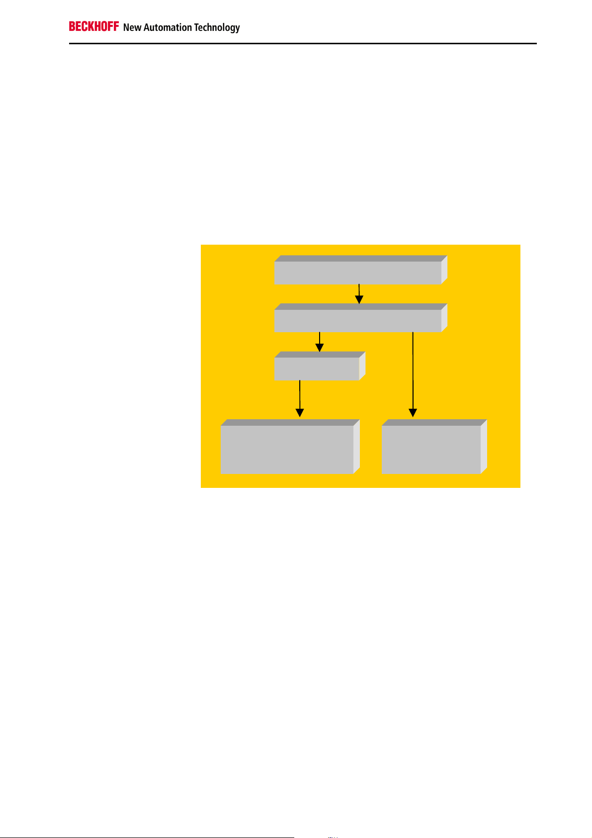
Start-up behaviour of the
Bus Terminal Controller
Immediately after being switched on, the Bus Terminal Controller checks,
in the course of a “self test”, all the functions of its components and the
communication of the K-Bus. The red I/O LED blinks while this is
happening. After completion of the self-test, the Bus Terminal Controller
starts to test the attached Bus Terminals (in a "Bus Terminal test"), and
reads in the configuration. An internal structure list is created from the Bus
Terminal configuration. In case of an error, the Bus Terminal Controller
enters the „STOP“ state. Once the start-up has completed without error,
the Bus Terminal Controller enters the "fieldbus start" state.
Basic Principles
Power On self test
Bus Terminal test
Structure list
OK
Error
PLC start /
Communication start
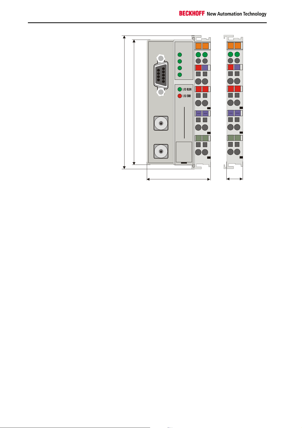
Mechanical structure
The system of the Beckhoff Bus Terminals is characterised by low physical
volume and high modularity. When planning a project it must be assumed
that at least one Bus Coupler and a number of Bus Terminals will be used.
The mechanical dimensions of the Bus Couplers are independent of the
fieldbus system. If large plugs are used, such as, for example, certain bus
plugs for the Profibus, the maximum height of the housing can be
exceeded.
Stop
BC7300 11
Page 12
Basic Principles
020201
01
+++
+
PEPEPE
PE
RUN
MODBUS
24V
24V
4
3
2
1
0
0
47
12
Dimensions of a Bus
Coupler in mm
4
9
RX
TX
PLC
F
F
0
1
9
2
8
3
7
4
6
5
O
H
K
C
E
B
0
1
9
8
7
6
5
0V
0
0
3
7
C
B
0V
The total width in practical cases is composed of the width of the Bus
Coupler with the bus end terminal and the width of the Bus Terminals in
use. Depending on function, the Bus Terminals are 12 or 24 mm wide. The
front wiring increases the total height of 68 mm by about 5 to 10 mm,
depending on the wire thickness.
Assembly and connection
The Bus Coupler and all the Bus Terminals can be clipped by light
pressure onto a 35 mm C-mounting rail. A locking mechanism prevents
the individual housings from being pulled off again. For removal from the
mounting rail the orange coloured tension strap releases the latching
mechanism, allowing the housing to be pulled off the rail without any force.
Work should only be carried out on the Bus Terminals and the Bus Coupler
when switched off. Pulling out and inserting under power can cause
undefined states to be temporarily caused. (A reset of the Bus Coupler, for
example).
Maximum number of
terminals
Up to 64 Bus Terminals can be attached to the Bus Coupler on the right
hand side. When plugging the components together, be sure to assemble
the housings with groove and tongue against each other. A properly
working connection can not be made by pushing the housings together on
the mounting rail. When correctly assembled, no significant gap can be
seen between the attached housings.
The right hand part of the Bus Coupler can be compared to a Bus
Terminal. Eight connections on the top permit connection with solid or fine
wires. The connection is implemented with the aid of a spring device. The
spring-loaded terminal is opened with a screwdriver or rod, by exerting
gentle pressure in the opening above the terminal. The wire can be
inserted into the terminal without any force. The terminal closes
automatically when the pressure is released, holding the wire securely and
permanently.
The connection between the bus coupler and the bus terminals is
automatically realised by pushing the components together. The transfer of
the data and the supply voltage for the intelligent electronics in the Bus
Terminals is performed by the K-Bus. The supply of the field electronics is
performed for the digital Bus Terminals through the power contacts.
BC7300 12
Page 13

Plugging together the power contacts creates a supply rail. Note the circuit
diagrams for the Bus Terminals, since some Bus Terminals do not loop
these power contacts through, or only do so partially (e.g. analog Bus
Terminals or 4 channel digital Bus Terminals). The potential feed terminals
interrupt the power contacts, and represent the start of a new supply rail.
The Bus Coupler can also be made use of to feed the power contacts.
Insulation testing
PE power contacts
The power contact labelled “PE” can be used as a protective earth. For
safety reasons this contact mates first when plugging together, and can
ground short-circuit currents of up to 125 A. Note that, for reasons of
electromagnetic compatibility, the PE contacts are capacitatively coupled to
the mounting rail. This can both lead to misleading results and to damaging
the terminal during insulation testing. (e.g.: breakdown of the insulation
from a 230 V power user to the PE conductor.) The PE conductor to the
Bus Coupler must be disconnected for the insulation testing. In order to
uncouple further feed locations for the purposes of testing, the feed
terminals can be pulled at least 10 mm out from the connected group of
other terminals. In that case, the PE conductors do not have to be
disconnected.
The “PE” power contact must not be used for other potentials.
Basic Principles
BC7300 13
Page 14
Basic Principles
Technical data
The MODBUS – the fieldbus-specific electrical data is listed in this section.
The following table gives an overview of all the data:
Technical data BC7300
Supply voltage
Input current
Power-on surge
K Bus supply current up to
Configuration facility
Number of Bus Terminals
Digital peripheral signals
Analog peripheral signals
Baud rate
Protocol
Bus connection
Voltage of the
power contact
Power contacts current
drawn
Electric strength
Typical weight
Operating temperature
Storage temperature
Relative humidity
Vibrations/Shock resistance
EMC resistance burst / ESD
Installation position
Type of protection
PLC data
Programmability
Program size
Program memory
Data memory
Remanent flags
Runtime system
PLC cycle time
Programming languages
Station addresses
Baud rate in programming
mode
24 V DC
70mA +
(total K-Bus current)/4
500 mA max.
2.5 x steady operating current
1750 mA max.
via KS2000 or the controller
64
256 inputs/outputs
128 inputs/outputs
From 150 baud to 38400 baud
RTU and ASCII
D-Sub RS 485
9-pin
24 V DC / AC max.
10 A max.
500 Veff (power contact / supply voltage / fieldbus)
none
170 g
0°C ... +55°C
-20°C ... +85°C
95% without dew formation
conforms to IEC 68-2-6 / IEC 68-2-27
conforms to EN 50082 (ESD, Burst) / EN 50081
any
IP20
via programming interface (TwinCAT BC/TwinCAT)
approx. 3000 PLC statements
32 kbytes / 96 kbytes
32 kbytes / 64 kbytes
512 bytes
1 PLC task
approx. 3 ms for 1000 instructions (including K-Bus I/O cycle)
IL, LD, FBD, SFC, ST
selectable to 99 via DIP switch
0 Programming mode and configuration mode
1 – 99 Slave address
19,200 baud, 8 data bits, even parity, one stop bit
Current consumption on
the K-Bus
The Bus Terminals require energy for the operation of the K-Bus
electronics, and this is supplied by the Bus Coupler. Find the current
consumption of the K-Bus from the catalogue, or from the appropriate data
sheets for the Bus Terminals. Consider the maximum output current of the
Bus Coupler that is available for supply of the Bus Terminals. A special
power supply terminal (KL9400) can be inserted at any location to insert
more power into the K-Bus. Refer to Beckhoff’s technical support
department regarding the use of a power supply terminal.
BC7300 14
Page 15

Basic Principles
Digital signals
(bit-oriented)
Analog signals
(byte-oriented)
Special signals and
interface
Default assignment of
inputs/outputs to the
process image
Peripheral Data in the Process Image
After being switched on, the Bus Coupler determines the configuration of
the inserted input/output terminals. The assignment of the physical slots for
the input/output channels and the addresses in the process image is
carried out automatically by the Bus Coupler.
The Bus Coupler creates an internal assignment list, in which the
input/output channels have a specific position in the process image. A
distinction is made here according to inputs and outputs, and according to
bit-oriented (digital) and byte-oriented (analog or complex) signal
processing.
Two groups are created, one for inputs and the other for outputs. Each
group has the byte-oriented channels in ascending sequence starting from
the lowest address. The bit-oriented channels are placed after this block.
The digital signals are bit-oriented. This means that one bit in the process
image is assigned to each channel. The Bus Coupler creates a memory
area containing the current input bits, and ensures that the bits in a second
memory area dedicated to the output channels are written out immediately.
The details of the assignment of the input and output channels to the
controller's process image is explained fully with the aid of an example in
the appendix.
The processing of all analog signals is always byte-oriented. Analog input
and output values are represented in memory by two bytes each. Values
are represented in SIGNED INTEGER or two‘s complement format. The
number "0" stands for the input/output value "0 V", "0 mA" or "4 mA". The
maximum value of an output or input value is represented, according to the
standard settings, by "7FFF" (hex). Negative input or output values, e.g. 10 V, are represented from "8000" (hex). The intermediate values are
correspondingly proportional. A range with a resolution of 15 bits is not
achieved for all inputs and outputs. If the actual resolution is 12 bits, the
last three bits have no effect in outputs, while as inputs they are read as
"0". Each channel also has a control and status byte. The control and
status byte is the lowest value byte. The master configuration software
must specify whether the control/status byte is also mapped into the
controller. An analog channel is represented in the process image by 2
bytes of user data.
A Bus Coupler supports Bus Terminals with other interfaces such as
RS232, RS485, incremental encoder and others. These signals can be
considered similarly to the analog signals named above. For some special
signals the bit width of 16 is not sufficient. The Bus Coupler can support
any byte width.
Once it has been switched on, the Bus Coupler finds out how many Bus
Terminals are inserted, and creates an assignment list. The analog and
digital channels, divided into inputs and outputs, are assembled into
separate parts of this list. The assignment starts on the left next to the Bus
Coupler. The software in the Bus Coupler collects the individual entries for
each of the channels in order to create the assignment list counting from
left to right.
BC7300 15
Page 16

Basic Principles
Four groups are distinguished in the assignment:
Functional type of the channel Assignment level
1.
2.
3.
4
Analog outputs assignment by bytes
Digital outputs assignment by bits
Analog inputs assignment by bytes
Digital inputs assignment by bits
Analog inputs and outputs here also represent other Bus Terminals with
complex multi-byte signals (RS232, SSI sensor interface, ...)
Data consistency
Items of data are said to be consistent if their content all belongs together,
and if they are transmitted as a single block. Examples of data items that
belong together are: 1. the high and low bytes of an analog value (word
consistency), and 2. a control/status byte and the associated parameter
word for access to the registers. Data consistency in the interaction of
peripheral devices and their controllers is, in a basic sense, only assured
for a single byte. In other words, the bits of a byte are output or read in
together. Byte consistency is sufficient for handling digital signals.
Whenever values have a length of more than 8 bits, analog values for
instance, the consistency must be extended. The different bus systems
guarantee consistency up to the required length. Correct transfer of the
consistent data from the bus system master to the controller is important.
The corresponding manual for the bus system will provide a detailed
description of the correct procedure, in particular the description of the
used master interfaces. Those chapters of this manual that deal with the
fieldbus refer to the most widespread interfaces.
Complex signal processing
All the byte-oriented signal channels such as RS232, RS485 or
incremental encoders operate to some extent with byte lengths of more
than two. Apart from the difference in length, they are always handled
similarly to the analog signals.
Start-up procedure and Diagnostics
After switching on, the Bus Coupler immediately checks the connected
configuration. Error-free start-up is signalled by extinction of the red LED
“I/O ERR“. If the “I/O ERR” LED blinks, an error in the area of the terminals
is indicated. The error code can be determined from the frequency and
number of blinks. This permits rapid rectification of the error.
The diagnostic LEDs
The Bus Coupler has two groups of LEDs for the display of status. The
upper group with four LEDs indicates the status of the respective fieldbus.
The significance of the “fieldbus status“ LED is explained in the relevant
sections of this manual - it conforms to conventional fieldbus displays.
On the upper right hand side of the Bus Couplers are two more green
LEDs that indicate the supply voltage. The left hand LED indicates the 24 V
supply of the Bus Coupler. The right hand LED signals the supply to the
power contacts.
Local errors
Two LEDs, the “I/O LEDs”, in the area below the field bus status LEDs
referred to above, serve to indicate the operating status of the Bus
Terminals and the connections to these terminals. The green LED lights up
in order to indicate fault-free operation. The red LED blinks with two
different frequencies in order to indicate an error.
BC7300 16
Page 17

The error is encoded in the blinks as follows:
Blink code
Fast blinking
First slow sequence
Second slow sequence
Basic Principles
Start of the error code
Error code
Error code argument
Error code Error
argument
Persistent,
continuous
blinking
1 pulse
2 pulses
3 pulses
4 pulses
5 pulses
9 pulses
14 pulses
15 pulses
16 pulses
EMC problems - Check power supply for overvoltage or
0
1
2
0
n (n > 0)
0 K-Bus command error - No Bus Terminal connected; attach Bus
0
n
n K-Bus error with register
0
n (n>0)
n Bus Terminal n has the wrong format - Start the coupler again, and if the error
n Number of Bus Terminals is no longer
n Length of the K-Bus data is no longer
Start of the error code Error type Error location
Description Remedy
undervoltage peaks
- Implement EMC measures
- If a K-Bus error is present, it can be
localised by a restart of the coupler (by
switching it off and then on again)
EEPROM checksum error
Inline code buffer overflow
Unknown data type
Programmed configuration
Incorrect table entry / Bus Coupler
Incorrect table comparison (Bus
Terminal n)
K-Bus data error
Break behind Bus Terminal n (0:
coupler)
communication with Bus Terminal n
Checksum error in program flash
memory
Bus Terminal n is not consistent with
the configuration that existed at boot
image entry
correct
correct
- Set manufacturer’s setting with the KS2000
- Connect fewer Bus Terminals; too many
entries in the table for the programmed
configuration
- Software update required for the coupler
- Check programmed configuration for
correctness
- Incorrect table entry / Bus Coupler
Terminals.
- One of the Bus Terminals is defective; halve
the number of Bus Terminals attached and
check whether the error is still present with
the remaining Bus Terminals. Repeat until the
defective Bus Terminal is located.
- Check whether the n+1 Bus Terminal is
correctly connected; replace if necessary.
– Check whether the Bus End Terminal 9010
is connected.
Exchange Bus Terminals
Transmit program to the BC7300 again
Check the nth Bus Terminal. If a new Bus
Terminal is to be inserted, delete the boot
project (manufacturer's setting)
occurs again then exchange the Bus Terminal
- Start the coupler again, and if the error
occurs again after this, use the KS2000
software to set manufacturer’s settings
- Start the coupler again, and if the error
occurs again after this, use the KS2000
software to set manufacturer’s settings
The number of pulses (n) indicates the position of the last Bus Terminal
before the fault. Passive Bus Terminals, such as a power feed terminal, are
not included in the count.
In the case of some errors, rectification does not cause the Bus Coupler to
leave the blink sequence. The Bus Coupler stays in the "Stop" state. The
Bus Coupler can only be re-started either by switching the power supply off
and on again, or by a software reset.
Insertion and removal of Bus Terminals is only permitted when switched
BC7300 17
Page 18

Basic Principles
WD
RX
TX
PLC
MODBUS
off. The electronics in the Bus Terminals and in the Bus Coupler are
protected to a large measure against damage, but incorrect function and
damage cannot be ruled out if they are plugged in under power.
The occurrence of a fault in the course of operation does not immediately
trigger the display of error codes by the LEDs. The Bus Coupler must be
requested to diagnose the Bus Terminals. The diagnostic request is
generated after switching on.
MODBUS LEDs
LED: on off
WD Watchdog is active Watchdog is not yet running
or the watchdog time has elapsed
RX Receive Data
Data is being received
TX Transmit Data
Data is being transmitted
PLC Program running
LED flashes while a boot project is being created
WD
If a K-Bus error occurs during operation, the procedures for reaction to a KBus error are executed in accordance with the parameterisation. If the KBus error occurs during booting, the slave is not included in the data
exchange.
Fieldbus errors
A fieldbus error only occurs when the watchdog (WD) period has elapsed.
The watchdog is preset to 1000 ms. The WD is activated as soon as a
"write" access has been made to the coupler's process data (WD LED
goes on). After this, another "write" command must be sent to the process
data within the set WD time, in order to start the WD from zero again.
Once a WD error has occurred, data communication can only be restarted
by resetting the coupler (see "Coupler Reset", under Diagnostics).
The maximum watchdog time is 65000 ms, and it can be set by rotary
switch or via the KS2000 software.
BC7300 18
Page 19

020201
01
+++
+
PEPEPE
PE
RUN
24V
0
9
8
7
6
3
2
1
0
9
8
7
6
3
2
1
B
K
7
3
0
0
02
01
+
+
PE
PE
02
01
+
+
PE
PE
02
01
+
+
PE
PE
020201
01
PE
4
3
2
1
3
2
02
01
02
01
PE
PE
02
01
PE
PE
020201
01
+++
+
PEPEPE
PE
RUN
MODBUS
24V
0
9
4
3
2
1
0
9
4
3
2
1
020102
01
+
+
PE
PE
02
01
+
+
PE
PE
02
01
+
+
PE
PE
MODBUS
Basic Principles
The MODBUS is a master-slave bus system in which only one device (the
master) actively starts a transaction (queries). The passive device (the
slave) then sends an answer (response) if the telegram was directly
addressed to it and provided that it has no errors.
Bus Topology
The BK7300 uses the RS485 physical data transmission. This means that
a two-wire cable is needed for the data transmission. The communication
structure corresponds to the linear topology. At the beginning and end of
the lines the bus requires termination resistors. The structure of the
Modbus network is similar to that of PROFIBUS.
0201
MODBUS
RX
0V
TX
4
5
BECKHOFF
4
5
MODBUS
0
1
9
8
7
4
6
5
0
9
8
7
6
5
0201
RUN
RX
24V
0V
TX
+ +
+++
BECKHOFF
BK 7300
PE PE
PEPEPE
+
+ +
+ +
RX
0V
TX
8
7
6
5
BECKHOFF
BK 7300
8
7
6
5
Broadcast function
Beckhoff Bus Terminal Controllers support the broadcast function. For this
purpose the slave address in the telegram must be set to "00". Slaves do
not answer a broadcast. Not all functions are supported.
Functions that support a broadcast:
• 5 Force single coil
• 6 Preset single register
• 15 Force multiple coils
• 16 Preset multiple register
PIN assignment
The BC7300 uses RS485 for the data transmission. A screened two-wire
cable is sufficient. The connection to the coupler is a 9-pin sub-D socket.
The data line is connected to PIN 3 and PIN 8.
BC7300 19
Page 20

MODBUS
1
5: GND
3: RxD/TxD
RxD/TxD (3)
TxD/RxD (8)
5 V (6)
Cable
Sub-D socket
Bus termination
BC7300
TxD/RxD (3)
RxD/TxD (8)
Abschirmung
BC7300
RxD/TxD (3)
TxD/RxD (8)
8: RxD/TxD
6: 5 V
The MODBUS requires termination resistors at the beginning and end of
the bus lines.
GND (5)
Process Data and Memory Map
The following example illustrates how the process image is constructed in
the Bus Terminal Controller, and the functions of the MODBUS telegram
with which digital and analog values can be read.
The Bus Terminal Controller has two process images. One is the fieldbus
interface and the other is the process image on the Bus Terminal
Controller. Bus Terminals can be assigned to one or the other process
image. The PLC variables offer an interface between these two process
images.
MODBUS
The input process image of the BC7300 starts from address 0x0000. All
the byte-oriented Bus Terminals (see Appendix) are entered here into the
process image first. The bit-oriented Bus Terminals them follow, and each
word (16 bit) is filled before starting a new one. The PLC variables are
entered into the process image last.
The output process image starts at address 0x0800. The entry begins
again here with the byte-oriented Bus Terminals, continues with the bitoriented Bus Terminals and finally the PLC variables.
All the digital signals can be directly addressed with functions 1, 2, 5 and
15.
20 BC7300
Page 21

PE
6
6
+
PE
PE
PEPEPEPEPE
PE
Bus Terminal Controller
The process image in the Bus Terminal Controller ignores all the Bus
Terminals that have been assigned to the MODBUS process image. The
controller first enters all the byte-oriented Bus Terminals, following the
sequence with which they are plugged in. The digital Bus Terminals come
next. The PLC variables are positioned from addresses %I128 and
%Q128.
Example
MODBUS
RUN
RX
TX
PLC
0
1
9
2
8
3
7
4
5
0
1
9
2
8
3
7
4
5
02
24V
0V
+ +
PE P E
+ +
PE P E
+ +
BECKHOFF
BC 7300
PEPEPE
+ +
PE P E
+
PE P E
POS 1 KL1012 MODBUS terminal
POS 2 KL1012 BC7300 terminal
POS 3 KL2012 MODBUS terminal
POS 4 KL2012 BC7300 terminal
POS 5 KL3002 MODBUS terminal
POS 6 KL3002 BC7300 complex terminal
POS 7 KL3002 BC7300 compact terminal
POS 8 KL4032 MODBUS terminal
POS 9 KL4032 BC7300 complex terminal
POS 10 KL4002 BC7300 compact terminal
KL9010
PLC Variables
POS 11 16 bytes INPUT
POS 12 16 bytes OUTPUT
BC7300 21
Page 22

MODBUS
MODBUS example
MODBUS Process Image
Terminals
POS 1. Terminal 2 digital inputs
POS 3. Terminal 2 digital outputs
POS 5. Terminal 2 analog inputs
POS 8. Terminal 2 analog outputs
PLC variables 16 byte inputs
PLC variables 16 byte outputs
BC7300 Process Image
Example for the BC7300
Byte address Terminal Inputs Terminal Outputs
128..143
Functions Offset Length
4, 23 0x0802 16 bit
2 0x0000
3, 6, 16, 23 0x0002 16 bit
1, 5, 15 0x0000
4, 23 0x0800
3, 6, 16, 23 0x0000
4, 23 0x0803
3, 6, 16, 23 0x0003
0
KL3002 (POS 6)
1
2
3
4
5
6
7
8
KL3002 (POS 7)
9
10
11
12
KL4032 (POS 9)
13
14
15
16
17
18
19
20
KL1012 (POS 2)
21
PLC Variables PLC
Status Control
- Data 0 Data 0
Data 1 Data 1
Status Control
- Data 0 Data 0
Data 1
Data 0 Control
Data 1 Data 0 Data 0
Data 1 Data 1
Status Control
- Data 0 Data 0
Data 1
Status Data 0
- Data 1
Data 0 Data 0
Data 1
Bit 0/1 Bit 0/1
-
0x0001
0x0001
0x0801
0x0001
0x0804
0x0805
0x0806
0x0807
0x0808
0x0809
0x080A
0x0004
0x0005
0x0006
0x0007
0x0008
0x0009
0x000A
KL3002
(POS 6)
KL4032
(POS 9)
KL4032
(POS 10)
KL2112
(POS 4)
Variables
1 bit
1 bit
1 bit
1 bit
16 bit
16 bit
16 bit
16 bit
16 bit
16 bit
16 bit
16 bit
16 bit
16 bit
16 bit
16 bit
16 bit
16 bit
16 bit
16 bit
16 bit
16 bit
16 bit
16 bit
Data 1
Data 1
Data 1
-
22 BC7300
Page 23

Assignment of the Bus Terminals
In the default setting, all the Bus Terminals are assigned to the Bus
Terminal Controller. This can be changed with the KS2000 software. The
assignment of the terminals is specified in Table 1 of the BC7300.
Compact
Hex Bin Description
0 00 The Bus Terminal is assigned to the MODBUS, and byte-
1 01 No function
2 10 The Bus Terminal is assigned to the BC, and byte-oriented
3 11 The Bus Terminal is assigned to the BC, and byte-oriented
Compact evaluation of a byte-oriented Bus Terminal means that only the
user data is transmitted.
Example: a KL3xx2 has 2 input words, and a KL4xx2 has 2 output words.
Complex
Complex evaluation of a byte-oriented Bus Terminal means that the user
data and the control and status byte are transmitted.
Example: a KL3xx2 has 4 input words and 4 output words; the same
applies to a KL4xx2.
You will find further information in the documentation for the Bus
Terminals.
Table 1 Default Description
Offset 4
Offset 5
Offset 6
Offset 7
Offset 8
Offset 9
Offset 10
Offset 11
0xFFFF 1.-8. terminal
0xFFFF 9.-16. terminal
0xFFFF 17.-24. terminal
0xFFFF 25.-32. terminal
0xFFFF 33.-40. terminal
0xFFFF 41.-48. terminal
0xFFFF 49.-56. terminal
0xFFFF 57.-64. terminal
KS2000 example
As from Version 2.3.2, the KS2000 software permits the adaptation of the
Bus Terminals to be set via a dialogue. You can update your KS2000
software at www.Beckhoff.de.
oriented Bus Terminals are given compact mapping (user
data only)
Bus Terminals are given compact mapping (user data only)
Bus Terminals are given complex mapping (with control
and status)
BC7300 23
Page 24

MODBUS
Setting and Parameterisation of the
MODBUS
Example
Now you want to set a new rate of 1200 baud
Incorrect Entry
KS2000
The MODBUS is parameterised by means of the rotary switch on the
BC7300. Only the Bus Terminal Controller's end terminal may be inserted
for this.
Only plug the KL9010 into the BC7300. Use the rotary switch to select the
parameters. The x10 address switch is used to select the parameter, while
the x1 address switch is used for the associated setting. The settings can
be found in the table. Connect the Bus Coupler's 24 V supply, and the
Modbus coupler will now start up in parameterisation mode. The LEDs WD,
RX, TX and ERROR are now toggled, and the LEDs I/O RUN and I/O ERR
give the function value.
You want to check whether the correct baud rate has been set.
1. Switch off the Bus Coupler's 24 V supply
2. Remove all the terminals except the KL9010 end terminal
3. Set the x10 address selection switch to 0 and the x1 switch to 3
4. Switch on the Bus Coupler's 24 V supply again
The coupler indicates the set baud rate via the LEDs.
3 x flashes of the I/O RUN and I/O ERR LEDs means 9600 baud
WD,RX,TX,ERROR LEDs
1 2 3 1 2 3 1 2 3 1 2 3
I/O Run, I/O ERR
5. Switch off the Bus Coupler's 24 V supply
6. Set the x10 address selection switch to 3 and the x1 switch to 6
7. Switch on the Bus Coupler's 24 V supply again
The Bus Coupler indicates the new set baud rate via the LEDs.
6 x flashes of the I/O RUN and I/O ERR LEDs means 1200 baud
If a parameter is set that the MODBUS Bus Terminal Controller does not
recognise, this is indicated by a constant even flashing of the I/O RUN and
I/O ERR LEDs, while all the other LEDs remain off.
The parameter settings can also be carried out with the KS2000 software.
24 BC7300
Page 25

Parameterisation Table
Parameter x 10 x 1 Default Parameter value
0 1..9 - Indicates the parameter of the x 10 function
Modbus
Frame
Baud rate
End of Frame Time
Watchdog 100 ms
Watchdog 1000 ms
Factory setting
1
2
3
4 0..9 0 In ms for RTU mode (0 dependent on the baud
5 0..9 0 Watchdog x 100 ms
6 0..9 1 Watchdog x 1000 ms
9 9
1 RTU mode
2
1 8 data bits, no parity one stop bit
2 8 data bits even Parity one stop bit
3 8 data bits odd Parity one stop bit
4 7 data bits even Parity one stop bit
5 7 data bits odd Parity one stop bit
6 one stop bit
7 2 stop bits
8 8 data bits, no parity two stop bits
9 8 data bits even Parity two stop bits
10 8 data bits odd Parity two stop bits
11 7 data bits even Parity two stop bits
12
1 38400 baud
2 19200 baud
3 9600 baud
4 4800 baud
5 2400 baud
6 1200 baud
7 600 baud
8 300 baud
9
1
ASCII mode
1
7 data bits odd Parity two stop bits
3
150 baud
rate)
In seconds for ASCII mode (0 EOF time switched
off)
BC7300 25
Page 26

MODBUS
ASCII frame
RTU frame
The MODBUS Protocol
ASCII
In ASCII mode the telegram starts with a colon ( : ) character (0x3A), and
ends with a carriage return and a line feed (CRLF) (0x0D, 0x0A). The
characters transferred are represented in the ASCII code.
Start Address Function Data LRC END
1
charact
RTU
In RTU mode the protocol starts with a pause of 3.5 characters, and
finishes in the same way (illustrated in the diagram with T1-T2-T3-T4). The
characters permitted for transmission in all fields are hexadecimal 0... 9,
A..., F.
Start Address Function Data CRC
T1-T2-
T3-T4 1 charact
er
:
2
charact
ers
er
2
charact
ers
1
charact
er
n
charact
ers
n
charact
ers
2
charact
ers
Check
2
charact
ers
2
charact
ers
CRLF
END
T1-T2-
T3-T4
26 BC7300
Page 27

Functions
In the MODBUS protocol, the functions determine whether data are to be
read or written, and what kind of data is involved. In the ASCII protocol the
fourth and fifth bytes are function bytes, while in the RTU protocol it is the
second byte.
The Beckhoff MODBUS Bus Terminal Controller supports the following
functions:
Function Code Description
Read coil status
Read input status
Read holding registers
Read input registers
Force single coil
Preset single register
Diagnostics
Force multiple coils
Preset multiple registers
Read / Write Registers
1 Read digital outputs
2 Read digital inputs
3 Read analog outputs / GPR
4 Read analog inputs / GPR
5 Write one digital output
6 Write one analog output /
GPR
8 Read the MODBUS diagnostic register
15 Write a number of digital outputs
16 Write a number of analog
outputs / GPR
23 Write and read a number of process data outputs / GPRs
GPR – General Preset Register (see Modbus Interface)
The functions are briefly described in the next section and clarified with the
aid of an example.
READ COIL STATUS
Read Digital Outputs (Function 1)
Function 1 can be used to read the settings of the digital outputs.
In this example the first 10 digital outputs of slave number 11 are read. The
start address is zero. If an offset is to be entered, this is done in the "Start
address" field.
Query
Start address high
Byte Name Example RTU ASCII
Start frame
Slave address
Function code
Start address low
Count high
Count low
Error Check
LRC / CRC
End of frame
„:“ 0x3A
11 0x0B „0B“ 0x30, 0x42
1 0x01 „01“ 0x30, 0x31
0 0x00 „00“ 0x30, 0x30
0 0x00 „00“ 0x30, 0x30
0 0x00 „00“ 0x30, 0x30
10 0x0A „10“ 0x31, 0x30
0xBC
0xA7
t1-t2-t3 CRLF 0xD, 0xA
„E4“ 0x45, 0x34
Response
The Bus Terminal Controller answers with byte count 2, i.e. 2 bytes of data
are returned. The query was for 10 bits, and these are now distributed over
2 bytes. The third bit in the output process image of the BC7300 is set, and
the Bus Coupler returns a "4" in the first data byte.
BC7300 27
Page 28

MODBUS
READ INPUT STATUS
Read Digital Inputs (Function 2)
Function 2 can be used to read the digital input data.
In this example the first 10 digital inputs of slave number 11 are read. The
Byte Name Example RTU ASCII
Start frame
Slave address
Function code
Byte Count
Data bits 0..7
Data bits 8..15
Error Check
LRC / CRC
End of frame
start address is zero. If an offset is to be entered, this is done in the "Start
address" field.
Query
„:“ 0x3A
11 0x0B „0B“ 0x30, 0x42
1 0x01 „01“ 0x30, 0x31
2 0x02 „02“ 0x30, 0x32
4 0x04 „04“ 0x30, 0x34
0 0x00 „00“ 0x30, 0x30
0x23
0x3D
t1-t2-t3 CRLF 0xD, 0xA
„EE“ 0x45, 0x45
READ HOLDING
REGISTERS
Byte Name Example RTU ASCII
Start frame
Slave address
Function code
Start address high
Start address low
Count high
Count low
Error Check
LRC / CRC
End of frame
„:“ 0x3A
11 0x0B „0B“ 0x30, 0x42
2 0x02 „02“ 0x30, 0x32
0 0x00 „00“ 0x30, 0x30
0 0x00 „00“ 0x30, 0x30
0 0x00 „00“ 0x30, 0x30
10 0x0A „10“ 0x31, 0x30
0xF8
0xA7
t1-t2-t3 CRLF 0xD, 0xA
„E3“ 0x45, 0x33
Response
The Bus Terminal Controller answers with byte count 2, i.e. 2 bytes of data
are returned. The query was for 10 bits, and these are now distributed over
2 bytes. The first bit in the input process image of the BC7300 is set, and
the Bus Coupler returns a "1" in the first data byte.
Byte Name Example RTU ASCII
Start frame
Slave address
Function code
Byte Count
Data 0..7
Data 8..15
Error Check
LRC / CRC
End of frame
„:“ 0x3A
11 0x0B „0B“ 0x30, 0x42
2 0x02 „02“ 0x30, 0x32
2 0x02 „02“ 0x30, 0x32
1 0x01 „01“ 0x30, 0x31
0 0x00 „00“ 0x30, 0x30
0x20
0x29
t1-t2-t3 CRLF 0xD, 0xA
„F0“ 0x46, 0x30
Read Analog In/Outputs (Function 3) 1
Function 3 can be used to read the input and output words and the
registers.
In this example the first two analog outputs of slave number 11 are read.
The analog outputs begin at offset 0x800 (hex). The length indicates the
number of channels to be read.
1
From Firmware B4 reading with function 3 is allowed.
28 BC7300
Page 29

Query
READ INPUT REGISTER
Byte Name Example RTU ASCII
Start frame
Slave address
Function code
Start address high
Start address low
Count high
Count low
Error Check
LRC / CRC
End of frame
„:“ 0x3A
11 0x0B „0B“ 0x30, 0x42
3 0x03 „03“ 0x30, 0x33
8 0x08 „08“ 0x30, 0x38
0 0x00 „00“ 0x30, 0x30
0 0x00 „00“ 0x30, 0x30
2 0x02 „02“ 0x30, 0x32
0xC6
0xC1
t1-t2-t3 CRLF 0xD, 0xA
„E8“ 0x45, 0x38
Response
The Bus Terminal Controller answers with byte count 4, i.e. 4 bytes of data
are returned. The query was for 2 analog channels, and these are now
distributed over 2 words. In the analog output process image, the first
channel has the value 0x3FFF, while the second channel has the value
0x0.
Byte Name Example RTU ASCII
Start frame
Slave address
Function code
Count byte
Data 1 high byte
Data 1 low byte
Data 2 high byte
Data 2 low byte
Error Check
LRC / CRC
End of frame
„:“ 0x3A
11 0x0B „0B“ 0x30, 0x42
3 0x03 „03“ 0x30, 0x31
4 0x04 „04“ 0x30, 0x30
63 0x3F „3F“ 0x33, 0x46
255 0xFF „FF“ 0x46, 0x46
0 0x00 „00“ 0x30, 0x30
0 0x00 „00“ 0x30, 0x30
0xC6
0xC1
t1-t2-t3 CRLF 0xD, 0xA
„B0“ 0x42, 0x30
Read Analog Inputs (Function 4)
Function 4 is used to read the analog inputs.
In this example the first two analog inputs of slave number 11 are read.
The analog outputs begin at offset 0x0000 (hex). The length indicates the
number of words to be read. A KL3002 has 2 words of input data, which is
why the value to be entered in "Count low" is two.
Query
Start address high
Byte Name Example RTU ASCII
Start frame
Slave address
Function code
Start address low
Count high
Count low
Error Check
LRC / CRC
End of frame
„:“ 0x3A
11 0x0B „0B“ 0x30, 0x42
4 0x04 „04“ 0x30, 0x34
0 0x00 „00“ 0x30, 0x30
0 0x00 „00“ 0x30, 0x30
0 0x00 „00“ 0x30, 0x30
2 0x02 „02“ 0x30, 0x32
0x71
0x61
t1-t2-t3 CRLF 0xD, 0xA
„EF“ 0x45, 0x46
Response
The Bus Terminal Controller answers with byte count 4, i.e. 4 bytes of data
are returned. The query was for 2 analog channels, and these will now be
BC7300 29
Page 30

MODBUS
distributed over 2 words. In the analog input process image, the first
channel has the value 0x0038, while the second channel has the value
0x3F1B.
FORCE SINGLE COIL
Writing a Digital Output (Function 5)
Function 5 can be used to write a digital output. In this example the third
digital output of slave number 11 is written. The digital outputs begin at
Byte Name Example RTU ASCII
Start frame
Slave address
Function code
Count byte
Data 1 high byte
Data 1 low byte
Data 2 high byte
Data 2 low byte
Error Check
LRC / CRC
End of frame
offset 0x0000 (hex). The digital value is located in the high byte of the data.
To switch the output on, "Data high" must contain 0xFF (hex), while 0x00
(hex) is used to switch the output off again. "Data low" must contain 0x00
(hex).
Query
„:“ 0x3A
11 0x0B „0B“ 0x30, 0x42
4 0x04 „04“ 0x30, 0x34
4 0x04 „04“ 0x30, 0x30
0 0x00 „00“ 0x30, 0x30
56 0x38 „38“ 0x33, 0x38
63 0x3F „3F“ 0x33, 0x46
11 0x0B „0B“ 0x30, 0x42
0x80
0x7E
t1-t2-t3 CRLF 0xD, 0xA
„6A“ 0x36, 0x41
PRESET SINGLE
REGISTER
Byte Name Example RTU ASCII
Start frame
Slave address
Function code
Start address high
Start address low
Data high
Data low
Error Check
LRC / CRC
End of frame
„:“ 0x3A
11 0x0B „0B“ 0x30, 0x42
5 0x05 „05“ 0x30, 0x35
0 0x00 „00“ 0x30, 0x30
2 0x02 „02“ 0x30, 0x32
255 0xFF „FF“ 0x46, 0x46
0 0x00 „00“ 0x30, 0x32
0x2D
0x50
t1-t2-t3 CRLF 0xD, 0xA
„EF“ 0x45, 0x46
Response
The Bus Terminal Controller answers with the same telegram.
Byte Name Example RTU ASCII
Start frame
Slave address
Function code
Start address high
Start address low
Data high
Data low
Error Check
LRC / CRC
End of frame
„:“ 0x3A
11 0x0B „0B“ 0x30, 0x42
5 0x05 „05“ 0x30, 0x35
0 0x00 „00“ 0x30, 0x30
2 0x02 „02“ 0x30, 0x32
255 0xFF „FF“ 0x46, 0x46
0 0x00 „00“ 0x30, 0x32
0x2D
0x50
t1-t2-t3 CRLF 0xD, 0xA
„EF“ 0x45, 0x46
Writing an Analog Output (Function 6)
Function 6 can be used to access the output process image and the
interface.
The first analog output of slave number 11 is written with function 6. The
analog outputs begin at offset 0x0800 (hex). Here again the offset always
describes a word. This means offset 0x0803 refers to the fourth word in the
output process image.
30 BC7300
Page 31

FORCE MULTIPLE COILS
Query
Byte Name Example RTU ASCII
Start frame
Slave address
Function code
Start address high
Start address low
Data high
Data low
Error Check
LRC / CRC
End of frame
„:“ 0x3A
11 0x0B „0B“ 0x30, 0x42
6 0x06 „06“ 0x30, 0x36
8 0x08 „08“ 0x30, 0x38
0 0x00 „00“ 0x30, 0x30
63 0x3F „3F“ 0x33, 0x46
255 0xFF „FF“ 0x46, 0x46
0xDA
0xB0
t1-t2-t3 CRLF 0xD, 0xA
„A9“ 0x41, 0x39
Response
The Bus Terminal Controller answers with the same telegram.
Byte Name Example RTU ASCII
Start frame
Slave address
Function code
Start address high
Start address low
Data high
Data low
Error Check
LRC / CRC
End of frame
„:“ 0x3A
11 0x0B „0B“ 0x30, 0x42
6 0x06 „06“ 0x30, 0x36
8 0x08 „08“ 0x30, 0x38
0 0x00 „00“ 0x30, 0x30
63 0x3F „3F“ 0x33, 0x46
255 0xFF „FF“ 0x46, 0x46
0xDA
0xB0
t1-t2-t3 CRLF 0xD, 0xA
„A9“ 0x41, 0x39
Writing a Number of Digital Outputs (Function 15)
Function 15 can be used to set or reset a number of digital outputs at the
same time.
In this example the first 20 digital outputs of slave number 11 are written.
The digital outputs begin at offset 0x0000 (hex). Here the offset always
describes a bit. Offset 0x0003 writes to the fourth bit in the output process
image. The length indicates the number of bits, and the "Byte count" is
composed from the combination all the bytes that are to be written.
Example: 20 bits – corresponds to 24 bits – count is 3 bytes (round up to
the nearest byte)
The data bytes contain the values for the individual bits.
In this example, the first 16 bits are set to "TRUE", while bits 17 to 20 are
"FALSE".
BC7300 31
Page 32

MODBUS
Query
PRESET MULTIPLE
REGISTERS
Byte Name Example RTU ASCII
Start frame
Slave address
Function code
Start address high
Start address low
Length high
Length low
Byte Count
Data 1 bit 0..7
Data 2 bit 8..15
Data 3 bit 16..19
Error Check
LRC / CRC
End of frame
„:“ 0x3A
11 0x0B „0B“ 0x30, 0x42
15 0x0F „0F“ 0x30, 0x46
0 0x00 „00“ 0x30, 0x30
0 0x00 „00“ 0x30, 0x30
0 0x00 „00“ 0x30, 0x30
20 0x14 „14“ 0x31, 0x34
3 0x03 „03“ 0x30, 0x33
255 0xFF „FF“ 0x46, 0x46
255 0xFF „FF“ 0x46, 0x46
0 0x00 „00“ 0x30, 0x30
0x01
0x95
t1-t2-t3 CRLF 0xD, 0xA
„D1“ 0x44, 0x31
Response
The Bus Terminal Controller answers with the same telegram.
Byte Name Example RTU ASCII
Start frame
Slave address
Function code
Start address high
Start address low
Data high
Data low
Error Check
LRC / CRC
End of frame
„:“ 0x3A
11 0x0B „0B“ 0x30, 0x42
15 0x0F „0F“ 0x30, 0x46
0 0x00 „00“ 0x30, 0x30
0 0x00 „00“ 0x30, 0x30
0 0x00 „00“ 0x30, 0x30
20 0x14 „14“ 0x30, 0x34
0xDA
0xB0
t1-t2-t3 CRLF 0xD, 0xA
„D2“ 0x44, 0x32
Writing a Number of Analog Outputs (Function 16)
Function 16 can be used to write a number of analog outputs. In this
example the first 2 analog output words of slave number 11 are written.
The analog outputs begin at offset 0x0800 (hex). Here the offset always
describes a word. Offset 0x0003 writes to the fourth word in the output
process image. The length indicates the number of words, and the "Byte
count" is composed from the combination all the bytes that are to be
written.
Example: 4 words – correspond to a byte count of 8
The data bytes contain the values for the analog outputs. In this example,
two words are to be written. The first word is to receive the value 0x7FFF
(hex), and the second word is to receive the value 0x3FFF.
32 BC7300
Page 33

Query
READ / WRITE
REGISTERS
Byte Name Example RTU ASCII
Start frame
Slave address
Function code
Start address high
Start address low
Length high
Length low
Byte Count
Data 1 byte 1
Data 1 byte 2
Data 2 byte 1
Data 2 byte 2
Error Check
LRC / CRC
End of frame
„:“ 0x3A
11 0x0B „0B“ 0x30, 0x42
16 0x10 „10“ 0x31, 0x30
8 0x08 „08“ 0x30, 0x38
0 0x00 „00“ 0x30, 0x30
0 0x00 „00“ 0x30, 0x30
2 0x02 „02“ 0x30, 0x32
4 0x04 „04“ 0x30, 0x34
127 0x7F „7F“ 0x37, 0x46
255 0xFF „FF“ 0x46, 0x46
63 0x3F „3F“ 0x33, 0x46
255 0xFF „FF“ 0x46, 0x46
0xCD
0xE3
t1-t2-t3 CRLF 0xD, 0xA
„1B“ 0x31, 0x42
Response
The Bus Terminal Controller replies with the start address and the length of
the transmitted words.
Byte Name Example RTU ASCII
Start frame
Slave address
Function code
Start address high
Start address low
Length high
Length low
Error Check
LRC / CRC
End of frame
„:“ 0x3A
11 0x0B „0B“ 0x30, 0x42
16 0x10 „10“ 0x31, 0x30
8 0x08 „08“ 0x30, 0x38
0 0x00 „00“ 0x30, 0x30
0 0x00 „00“ 0x30, 0x30
2 0x02 „02“ 0x30, 0x32
0x43
0x02
t1-t2-t3 CRLF 0xD, 0xA
„DB“ 0x44, 0x42
Writing and Reading Analog Outputs and Inputs
(Function 23)
A number of analog outputs can be written and a number of analog inputs
read with one telegram using function 23. In this example the first 2 analog
output words of slave number 11 are written, and the first two analog inputs
are read. The analog outputs start at offset 0x0800 (hex), while the inputs
start at offset 0x0000 (hex). Here the offset always describes a word.
Offset 0x0003 writes to the fourth word in the output process image. The
length indicates the number of words, and the "Byte count" is composed
from the combination all the bytes that are to be written.
Example: 4 words – correspond to a byte count of 8
The data bytes contain the values for the analog outputs. In this example,
two words are to be written. The first word is to receive the value 0x3FFF
(hex), and the second word is to receive the value 0x7FFF.
BC7300 33
Page 34

MODBUS
Query
Read start address
Read start address
Write start address
Write start address
Byte Name Example RTU ASCII
Start frame
Slave address
Function code
Read length high
Read length low
Write length high
Write length low
Byte Count
Data 1 high
Data1 low
Data 2 high
Data 2 low
Error Check
LRC / CRC
End of frame
„:“ 0x3A
11 0x0B „0B“ 0x30, 0x42
23 0x17 „17“ 0x31, 0x37
0 0x00 „00“ 0x30, 0x30
high
0 0x00 „00“ 0x30, 0x30
low
0 0x00 „00“ 0x30, 0x30
2 0x02 „02“ 0x30, 0x32
8 0x08 „08“ 0x30, 0x38
high
0 0x00 „00“ 0x30, 0x30
low
0 0x00 „00“ 0x30, 0x30
2 0x02 „02“ 0x30, 0x32
4 0x04 „04“ 0x30, 0x34
63 0x3F „3F“ 0x33, 0x46
255 0xFF „FF“ 0x46, 0x46
127 0x7F „7F“ 0x37, 0x46
255 0xFF „FF“ 0x46, 0x46
0x76
0xD3
T1-t2-t3 CRLF 0xD, 0xA
„12“ 0x31, 0x32
Response
The Bus Terminal Controller replies with the start address and the length of
the bytes to be transferred in "Byte count". The data information follows. In
this example the first word contains 0x0038 (hex) while the second word
contains 0x3F0B.
Byte Name Example RTU ASCII
Start frame
Slave address
Function code
Byte Count
Data 1 high
Data 1 low
Data 2 high
Data 2 low
Error Check
LRC / CRC
End of frame
„:“ 0x3A
11 0x0B „0B“ 0x30, 0x42
23 0x17 „17“ 0x31, 0x37
4 0x04 „04“ 0x30, 0x34
0 0x00 „00“ 0x30, 0x30
56 0x38 „38“ 0x33, 0x38
63 0x3F „3F“ 0x33, 0x46
11 0x0B „0B“ 0x30, 0x42
0x82
0xDD
t1-t2-t3 CRLF 0xD, 0xA
„58“ 0x35, 0x38
Diagnostics
In the MODBUS, function 08 provides a series of tests for examination of
the communication system between the master and the slave and for
inspection of a variety of internal error states within the slave. A broadcast
telegram is not supported.
The function uses a two-byte sub-function code field in the query to define
the test that is to be carried out. The slave outputs the function code and
the sub-function code as an answer.
The diagnostic queries use a two-byte data field to send diagnostics data
or control information to the slave.
34 BC7300
Page 35

EXAMPLE
Query
Byte Name Example RTU ASCII
Start frame
Slave address
Function code
Subfunction high
Subfunction low
Data high
Data low
Error Check
LRC / CRC
End of frame
„:“ 0x3A
11 0x0B „0B“ 0x30, 0x42
8 0x08 „08“ 0x30, 0x38
0 0x00 „00“ 0x30, 0x30
0 0x00 „00“ 0x30, 0x30
2 0x02 „02“ 0x30, 0x32
3 0x03 „03“ 0x30, 0x33
0xA1
0xC0
t1-t2-t3 CRLF 0xD, 0xA
„E8“ 0x45, 0x38
Response
Byte Name Example RTU ASCII
Start frame
Slave address
Function code
Subfunction high
Subfunction low
Data high
Data low
Error Check
LRC / CRC
End of frame
„:“ 0x3A
11 0x0B „0B“ 0x30, 0x42
8 0x08 „08“ 0x30, 0x38
0 0x00 „00“ 0x30, 0x30
0 0x00 „00“ 0x30, 0x30
2 0x02 „02“ 0x30, 0x32
3 0x03 „03“ 0x30, 0x33
0xA1
0xC0
t1-t2-t3 CRLF 0xD, 0xA
„E8“ 0x45, 0x38
Echoes a query (Sub-Function 0)
Sub-function 0 causes the data that is sent to the slave by the master to be
returned.
Bus Coupler Reset (Sub-Function 1)
Sub-function 1 re-initialises the BC7300. Error counters are reset, and the
coupler executes a self-test. No telegrams are either received or sent while
the coupler is being reset.
Sub-function Data field (query) Data field (response)
00 01 00 00 00 00
Delete All Counter Contents (Sub-Function 10)
Calling this sub-function deletes the contents of all error counters in the
coupler.
Sub-function Data field (query) Data field (response)
00 0B 00 00 Echo Query Data
Bus Communication Error Counter (Sub-Function 11)
Returns the number of faulty communications.
Sub-function Data field (query) Data field (response)
00 0C 00 00 CRC error counter
Error Answer Counter (Sub-Function 13)
This counter contains the number of error answer telegrams that the
coupler has sent.
Sub-function Data field (query) Data field (response)
00 0D 00 00 Error Answer Counter
BC7300 35
Page 36

MODBUS
Slave Answers (Sub-Function 14)
Contains the number of answers that the slave has sent.
Sub-function Data field (query) Data field (response)
00 0E 00 00 Slave Message Count
Unsent Slave Answers (Sub-Function 15)
Contains the number of answers that the slave has not sent. For example,
the slave does not send an answer to a broadcast message.
Sub-function Data field (query) Data field (response)
00 0F 00 00 Slave No Response
Number of Error Answers (Sub-Function 16)
Contains the number of error answers that the slave has sent.
Sub-function Data field (query) Data field (response)
00 10 00 00 Number of error
Count
answers
36 BC7300
Page 37

EXCEPTION RESPONSE
Example
BC7300 Error Answers
When the user sends the slave either a request or information that the Bus
Coupler does not understand, the BC7300 responds with an error report.
This answer contains the function and the error code. 0x80 is added to the
value returned by the function.
Code Name Meaning
1 ILLEGAL FUNCTION Function not implemented
2 ILLEGAL DATA
ADDRESS
3 ILLEGAL DATA VALUE Invalid parameter
4 SLAVE DEVICE ERROR Watchdog or K-Bus error
The following example contains an invalid "Start address".
Query
BYTE Contents Example
1 Slave address 0B
2 Function 01
3 Start address high 0D
4 Start address low FF
5 Data high FF
6 Data low 01
7 LRC
The slave's answer contains the function plus 0x80, together with error
code "02", i.e. an invalid address.
Response
BYTE Contents Example
1 Slave address 0B
2 Function 81
3 Error code 02
4 LRC
Invalid address or length
• Diagnostic functions
• Incorrect number of read/write
accesses to the register
BC7300 37
Page 38

Bus Terminal Controller
PLC Cycle Time
Bus Terminal Controller
PLC Cycle Time
PLC Cycle Time
The PLC cycle time determines the program’s repetition frequency. This
time is not deterministic. This means that when the program in the Bus
Terminal Controller needs more time, the PLC cycle time rises. If the
program needs less than the cycle time, it is repeated at intervals of the set
cycle time.
The processing of the MODBUS and the serial interfaces is executed in the
background time. This should be set to approx. 20 % of the PLC cycle
time.
Example of cycle time
optimisation
Mean cycle time
The „mean cycle time“ is measured in order to optimise the system. You
will find this item in PLC Control under Online\Coupler. About 20% – 30%
is added to this, and the result entered as the PLC cycle time. The
background time is then set to 20% of the PLC cycle time.
PLC cycle time = mean cycle time + 20% = 10 ms + 20% = 12 ms
Background time = PLC cycle time * 0.2 = 12 ms * 0.2 = 2.4 ms ≈ 2 ms
The measured cycle time also includes that required for the K-Bus update.
This results in a connection between the number of terminals that are
inserted and the cycle time. Before initiating the program, the Bus Terminal
Controller executes a K-Bus update, in order to interrogate the inputs. After
the program has been executed, the BC7300 carries out another K-Bus
update, in order to write the current outputs. The background time follows
this.
Mean cycle time 10 ms
Background
time
PLC Variables
PLC variables are variables that are situated in the BC7300 from
addresses %IB128 and %QB128. This offset can be shifted. These
addresses are not assigned to any terminal, so that signals or data can be
transmitted to or received from the master via the PLC variables. The
default setting is for 16 words of input and output. These can be changed
with the KS2000.
Remanent Variables
Retained or remanent variables are data that retain their value when
voltage is not present. In PLC Control this data is placed in the allocated
flags area. Following the default setting, this means that all the variables
from %MB0 - %MB63 are RETAIN data. The maximum setting is for 512
bytes, which can be set using the KS2000 software.
38 BC7300
Page 39

Bus Terminal Controller
Persistent Data2
The Persistent Data remain intact, even after a new program download and
a reset. Like the Retain Variables, they are stored in the flags area of the
Bus Terminal Controller.
Example: VarP1 AT %MB0: INT;
The Persistent Data are in the same area as the Retain Variables and also
start at %MB0. You first have to enable Retain Variables in order to
achieve a storage increase through the Persistent Data. By default, no
Persistent Variables are declared.
The Persistent Variable memory area must always be smaller or equal
than that of the Retain Variables.
The KS2000 software allows this area to be increased to a maximum of
512 bytes (Table 1, Register 18).
These data are deleted by a general reset.
2
From Firmware B4
BC7300 39
Page 40

Bus Terminal Controller
Allocated flags area
The allocated flags area offers a variety of further additional functions and
diagnostic facilities.
Cycle tick counter
The cycle tick counter starts at address %MB504. Each tick corresponds to
about 1 ms. The counter has 32 bits, and can also be written from the PLC
in order to set it to zero or to some other particular value.
Fieldbus diagnostics
Fieldbus diagnostics are located at flag words 508 and 509.
%MX508.0 "TRUE" watchdog time elapsed
The bit is set to "1" if a write telegram has been processed and no new write
telegram is sent to the Bus Terminal Controller within the watchdog time.
No other bits have any function.
K-Bus diagnostics
K-Bus diagnostics are located at flag words 510 and 511.
%MX510.0 "TRUE" K-Bus error
%MX510.1 "TRUE" configuration error
Flag byte
%MW508
%MW510
Data acces via Modbus
From the firmware B4 is it as well possible to access directly reading and
writing on the flag area. This access does not trigger the watchdog. That
means values which are written in this range, remain as well after a
watchdog error set.
Meaning
Bit 0: Fieldbus error
Bits 1-15: reserved
Bit 0: K-Bus error
Bit 1: Configuration error
Bits 2-15: reserved
40 BC7300
Page 41

Appendix
Appendix
Address Description
0x0000
0x00FF
0x0800
0x08FF
0x10000x1006
0x100A
0x100B
0x100C
0x1010
0x1011
0x1012
0x1013
0x1020
0x110A
0x110B
0x1120
0x400
0x40FF
Only Read
Read/Write
Bus Coupler status 15 14 13 12 11 10 9 8 7 6 5 4 3 2 1 0
0x100C
FB CNF KB
FB: Fieldbus error, watchdog time elapsed
KB: Terminal Bus error
CNF: BK configuration window
2 byte PLC interface/
2 byte diagnostic interface
MODBUS Interface
Process data interface
Inputs (%QBx)
Process data interface
Outputs (%IBx)
Bus Coupler identification
2 byte PLC interface
Terminal diagnostics
Bus Coupler status
Process image length in bits Analog outputs
Process image length in bits Analog inputs
Process image length in bits Digital outputs
Process image length in bits Digital inputs
Watchdog Current time in [ms] 1000
2 byte PLC interface
Terminal diagnostics
Watchdog Pre-defined time in [ms] 1000
Flag range3
%MB0 - %MB511
Registers in the complex terminals and Bus Coupler registers can both be
read or written using the 2 byte PLC interface. The complex terminal
registers are described in the associated terminal documentation. The Bus
Coupler registers can be used, for example, to read terminal bus
diagnostics data, the terminal composition or the cycle times, and the
programmed configuration can be written. It is also possible for a manual
terminal bus reset to be carried out. The 2-byte PLC interface requires two
bytes each of output and input data. They are handled using a special
protocol. A description of the 2 byte PLC interface, the registers available
in the Bus Couplers and of function blocks for various PLCs that implement
the 2 byte PLC interface can be supplied on request.
The terminals' error messages can be sent over the 2-byte diagnostic
interface. Terminal bus diagnostics must however be activated for this
purpose. The 2-byte diagnostic interface occupies two bytes each of output
and input data. They are handled using a special protocol. A description of
the 2 byte-diagnostic interface can be supplied on request.
3
From Firmware B4
BC7300 41
Page 42

Appendix
Modicon: „MODBUS Protocol Reference Guide“
Example 3200B2020000
Mapping the Bus Terminals
The precise assignment of the byte-oriented Bus Terminals may be found
in the Bus Terminal configuration guide.
The documentation is available on the product CD or on the Internet under
www.beckhoff.de.
Byte oriented Bus Terminals Bit oriented Bus Terminals
KL1501 KL10XX, KL11XX, KL12XX, KL17XX
KL2502
KL3XXX
KL4XXX
KL5XXX
KL6XXX
KL9110, KL9160, KL9210, KL9260
KL20XX, KL21XX, KL22XX, KL26XX
KL27XX
List of references
http://www.modicon.com
Software – Win-TECH
http://www.win-tech.com
Firmware
The label under the coupler will tell you which firmware is installed in the
Bus Coupler. (Fifth and sixth positions)
The current Firmware version is B2.
To update your firmware you need the KS2000 software and the
appropriate serial cable, supplied along with KS2000. You may find the
firmware under www.Beckhoff.de.
Table
Firmware Description
B1
Released version
B2
PLC optimized
B3
Internal version
B4
Modbus access to flag range
42 BC7300
Page 43

Example program on the
BC7300
Example Program
This example program makes use of the basic settings for the BC7300.
This makes it very easy to quickly include this Bus Terminal Controller in
the data exchange for the first time. The procedure is explained step by
step with the aid of a small example.
Explanation of the Program
The following very simple example should clarify the function and type of
data transmission with the aid of the PLC variables. The blinker block is
called in the MAIN program when the first input of the input terminal has
reached the value zero. The blinker block contains a pulse generator that is
fed to two counters. One of the counters increments output word 130, while
the other counts output word 128 downwards. Both of these output words
are what are known as PLC variables, and they are read by the MODBUS
master.
The Program in the Bus Terminal Controller
In order to generate this example program you need a BC7300, 2 x
KL2012, 2 x KL1002, 1 x KL9010 and a 24V DC mains power supply unit
(2A) with a cable and a connection on your MODBUS master to the
BC7300. The software you require is TwinCAT / TwinCAT BC and a
programming cable. This is included when TwinCAT BC or KS2000 is
supplied.
The first step is to create a program in the BC7300. For this purpose the
address selection switch is set to "00". This it the programming mode for
the Bus Terminal Controller. The MODBUS cannot be operated at the
same time, which means that the fieldbus connection must not be
connected. Connect the supply voltage and the supply to the power
contacts. The Bus Terminal Controller now boots. When booting is
complete the "I/O RUN" LED lights up on the BC7300. Insert the
programming cable into your PC's serial interface and into the
programming interface of the BC7300. Open the flap under the Beckhoff
logo to do this. Start TwinCAT or TwinCAT BC, and under File/New select
the item "BC serial". Confirm with "OK". Then select "ST" as the language,
and confirm with "OK". Now test communication with the BC by executing a
reset under Online/Coupler/K-Bus reset. If a message box then appears
with the number of Bus Terminals inserted (not counting the end terminal),
the communication has been successful. If, after about 15 seconds, a
"Communication error" message appears, check the cable, the address on
the BC7300 and the settings of the serial interface. You will find these
under Online/Communication parameters. The necessary setting is 19200
baud, 1 start bit, even parity.
MAIN block (PRG-ST)
Appendix
BC7300 43
Page 44

Appendix
Blink block (PRG-CRC)
Creating the BOOT Program
The next step is the creation of a boot project. To achieve this, select,
when you are logged in, Online/Create boot project. The PLC LED flashes
while the boot project is being created. Now set the MODBUS slave
address and switch the Bus Terminal Controller off and then on again.
Remove the programming cable, and connect the MODBUS cable.
MODBUS Communication
Function 4 is used in order to obtain the states of the counters in the two
16-bit output words in the MODBUS master.
44 BC7300
Page 45

Query
Start address high
Response
The Bus Terminal Controller answers with byte count 4, i.e. 4 bytes of data
Byte Name Example RTU Description
Slave address
Function code
Start address low
Count high
Count low
Error Check
LRC / CRC
End of frame
11 0x0B
4 0x04
0 0x00
0 0x00
0 0x00
2 0x02 Number of data words
0x71
0x61
t1-t2-t3
are returned. The query was for 2 input words, and these are now
distributed over 4 bytes.
Byte Name Example RTU Description
Start frame
Slave address
Function code
Count byte
Data 1 high byte
Data 1 low byte
Data 2 high byte
Data 2 low byte
Error Check
LRC / CRC
End of frame
11 0x0B
4 0x04
4 0x04 Number of data bytes
0 0x00 Address %QB129
56 0x38 Address %QB128
63 0x3F Address %QB131
11 0x0B Address %QB130
0x80
0x7E
t1-t2-t3
BC7300 45
Page 46

Questions and Answers
Questions and Answers
General
Problem
Solution
Problem
Solution
Example
Problem
Solution
Recommendation
No communication with the BC7300
You cannot log in with either KS2000 nor TwinCAT (BC).
Set the address selection switch to "00" and start the Bus Terminal
Controller again.
Mapping of the digital and the byte-oriented Bus Terminals
onto a fixed address
You want a constant start address for the digital inputs and outputs.
With the KS2000 software, you can enter an offset start value for the digital
inputs and outputs in table 0. The byte-oriented Bus Terminals should not
jut into this process image, i.e. no overlap should occur.
Table 0:
Register 19 offset for digital outputs
Register 20 offset for digital inputs
"0" is the default setting (automatic Bus Terminal mapping)
You have a KL3002 and a KL2012. In the default case, the KL3002 maps
onto %IB0- %IB7 and %QB0-QB7 in the memory. The digital output
terminal would now map to %QX8.0 and %QX8.1. As soon as you now plug
another byte-oriented Bus Terminal, the process image of the digital Bus
Terminal is moved to a higher memory. You can now pre-empt this by
entering 20 in register 19. This means that KL2012 now maps onto
%QX20.0 and %QX20.1.
Drop of the digital outputs
Your digital outputs drop away.
Your program takes longer than 100 ms. Because the internal K-Bus runs
synchronous with your PLC program, it is no longer triggered early enough,
and the Bus Terminal watchdog becomes active. This can be rectified by
triggering a short refresh of the K-Bus. The setting can be carried out with
the KS2000 software.
Table 1 register 17
LowByte cycle time to K-Bus refresh (<= 80 ms)
HighByte Retries
Enter 0x0350 in table 1, register 17, i.e. three retries, all at 80 ms.
Note that this causes the Bus Terminal watchdog to increase to 240 ms
during a fault condition (this is not true in case of a K-Bus error, where the
watchdog will remain at 100 ms).
46 BC7300
Page 47

Index
Allocated flags area 38
Answer counter 33
ASCII 24
Assembly 10
Background time 36
Baud rate 23
Bit-oriented terminals 13
Blink code 15
Broadcast 17
Bus Communication Error 33
Bus termination 18
Byte-oriented terminals 13
Coupler reset 33
Cycle tick counter 38
Cycle time 36
Data consistency 14
Delete All Counter Contents 33
Device description 5
Diagnostic LEDs 14
Diagnostic on the BC 38
Diagnostics 32
Dimensions 9
Electrical power supply 7
End terminal 6
Error Answer Counter 33
Error answers 35
Exception Response 35
Flags 38
Frame 23
Interfaces 7
K-Bus 6, 12
If you have suggestions to make or ideas about our documentation, please send us an e-mail,
stating the version number, at
Dokumentation@Beckhoff.de.
KS2000 8
List of references 40
Manufacturer’s setting 44
Mapping of digital Bus Terminals 44
Mechanical structure 9
Parameterisation 22
Parameterisation Table 23
Persistent Data 37
PLC Cycle Time 36
PLC Variables 36
Power contacts 7
Process Data 18
Protocol 24
Read analog inputs 27
Read analog outputs 26
Read digital inputs 26
Read digital outputs 25
Reading and writing inputs and outputs 31
Remanent Variables 36
RTU 24
Start-up procedure 14
Technical data 12
TwinCAT BC 8
Unsent Slave Answers 34
Watchdog 23
Writing a digital output 28
Writing a number of analog outputs 30
Writing a number of digital outputs 29
Writing an analog output 28
Index
BC7300 47
Page 48

Support and Service
Support and Service
Support and Service
Beckhoff and their partners around the world offer comprehensive support and service, making available
fast and competent assistance with all questions related to Beckhoff products and system solutions.
Beckhoff's branch offices and representatives
Please contact your Beckhoff branch office or representative for local support and service on Beckhoff
products!
The addresses of Beckhoff's branch offices and representatives round the world can be found on her
internet pages: http://www.beckhoff.com
You will also find further documentation for Beckhoff components there.
Beckhoff Headquarters
Beckhoff Automation GmbH
Eiserstr. 5
33415 Verl
Germany
phone: + 49 (0) 5246/963-0
fax: + 49 (0) 5246/963-198
e-mail: info@beckhoff.com
web: www.beckhoff.com
Beckhoff Support
Support offers you comprehensive technical assistance, helping you no only with the application of
individual Beckhoff products, but also with other, wide-ranging services:
• support
• design, programming and commissioning of complex automation systems
• and extensive training program for Beckhoff system components
hotline: + 49 (0) 5246/963-157
fax: + 49 (0) 5246/963-9157
e-mail: support@beckhoff.com
Beckhoff Service
The Beckhoff Service Center supports you in all matters of after-sales service:
• on-site service
• repair service
•
spare parts servive
• hotline service
hotline: + 49 (0) 5246/963-460
fax: + 49 (0) 5246/963-479
e-mail: service@beckhoff.com
48 BC7300
 Loading...