

Page 1
BC3150 - Bus Terminal
Controller for PROFIBUS
Version: 1.1.0
Date: 2006-02-10
Page 2

Page 3

Contents
Contents
BC3150 - Bus Terminal Controller for PROFIBUS
1. Foreword 4
Notes on the Documentation 4
Safety Instructions 5
Documentation Issue Status 6
2. Product Overview 7
BCxx50 - Overview 7
The Principle of the Bus Terminal 8
The Beckhoff Bus Terminal System 9
Technical Data 11
Technical Data - BCxx50 11
Technical Data - PROFIBUS DP 13
Technical Data - PLC 14
3. Mounting and Wiring 15
Mounting 15
Dimensions 15
Installation 16
Wiring 17
Potential Groups, Insulation Testing and PE 17
Power supply 19
Programming cable 20
PROFIBUS Connection 21
PROFIBUS Cabling 23
Fieldbus Components 1
Page 4

Contents
4. Parameterization and Commissioning 25
Start-up Behavior of the Bus Terminal Controller 25
Setting the slave address 26
Configuration 27
Overview 27
Creating a BX File 29
Downloading a BX Configuration 30
Uploading a BX Configuration 32
Bus Terminal Controller resources 34
ADS via Serial 36
ADS Connection via Serial Interface 36
PROFIBUS 37
PROFIBUS Settings 37
Master Configuration 38
Basic Device File (GSD) 38
Creating a TwinCAT PC File 39
Variable Mapping - PROFIBUS DP 41
BC3150 at 3rd party controller 42
SIEMENS S7 42
Configuration - Siemens S7 Controller 42
Configuration: Siemens S7 Controller with BX3100 43
K-Bus 46
K-Bus 46
PLC 48
Inserting a PLC project 48
Measuring the PLC Cycle Time 49
KS2000 50
KS2000 50
5. Programming 51
BCxx50 PLC features 51
TwinCAT PLC 52
TwinCAT PLC Error Codes 53
Remanent data 55
Allocated Flags 56
Local process image in delivery state 57
Mapping of the Bus Terminals 59
Local process image in the TwinCAT configuration 60
Creating a boot project 61
Communication between TwinCAT and BX/BCxx50 62
Up- and downloading of programs 63
2 Fieldbus Components
Page 5

Contents
Libraries 67
Übersicht 67
TcBaseBX 69
System Task Info 69
System Task Info Type 70
System Info 71
System Info Type 72
ADS 73
Local ADS Port Numbers 73
ADS Services 74
BX Debug Function 75
Overview 75
Program Transmission 76
Transmission via Serial Interface 76
Transmission via PROFIBUS 78
Process Image 80
PROFIBUS Process Image 80
6. PROFIBUS 81
System Introduction 81
Fieldbus Overview 81
PROFIBUS DP 85
PROFIBUS DPV1 87
Cables, Plugs and Switches 88
Topology 91
7. Error handling and diagnosis 92
Diagnostics 92
Diagnostic LEDs 94
8. Appendix 97
First steps with the BC3150 97
Moving from BC to BX 99
Firmware Update 102
General Operating Conditions 105
Standards for Device Testing 107
Bibliography 108
List of Abbreviations 109
Support and Service 110
Fieldbus Components 3
Page 6

Notes on the Documentation
1. Foreword
Notes on the Documentation
This description is only intended for the use of trained specialists in control and automation engineering who are
familiar with the applicable national standards. It is essential that the following notes and explanations are followed
when installing and commissioning these components.
Liability Conditions
The responsible staff must ensure that the application or use of the products described satisfy all the requirements for
safety, including all the relevant laws, regulations, guidelines and standards.
The documentation has been prepared with care. The products described are, however, constantly under
development. For that reason the documentation is not in every case checked for consistency with performance data,
standards or other characteristics. None of the statements of this manual represents a guarantee (Garantie) in the
meaning of § 443 BGB of the German Civil Code or a statement about the contractually expected fitness for a
particular purpose in the meaning of § 434 par. 1 sentence 1 BGB. In the event that it contains technical or editorial
errors, we retain the right to make alterations at any time and without warning. No claims for the modification of
products that have already been supplied may be made on the basis of the data, diagrams and descriptions in this
documentation.
© This documentation is copyrighted. Any reproduction or third party use of this publication, whether in whole or in
part, without the written permission of Beckhoff Automation GmbH, is forbidden.
4 Fieldbus Components
Page 7
Safety Instructions
Safety Instructions
Safety Rules
The responsible staff must ensure that the application or use of the products described satisfy all the requirements for
safety, including all the relevant laws, regulations, guidelines and standards.
State at Delivery
All the components are supplied in particular hardware and software configurations appropriate for the application.
Modifications to hardware or software configurations other than those described in the documentation are not
permitted, and nullify the liability of Beckhoff Automation GmbH.
Personnel Qualification
This description is only intended for the use of trained specialists in control and automation engineering who are
familiar with the applicable national standards.
Description of safety symbols
The following safety symbols are used in this operating manual. They are intended to alert the reader to the
associated safety instructions.
This symbol is intended to highlight risks for the life or health of personnel.
Danger
This symbol is intended to highlight risks for equipment, materials or the environment.
Warning
This symbol indicates information that contributes to better understanding.
Note
Fieldbus Components 5
Page 8

Safety Instructions
Documentation Issue Status
Version Comment
1.1.0 Notes to meet the UL requirements added.
•
1.0.1
1.0.0 First release (only German version available)
Chapter Creating a boot project corrected
•
minor routine corrections (typing errors, orthography etc.)
•
English version available
Firmware BC3150
To make a firmware update, you need a serial cable and the KS2000 Configuration Software or the firmware update
program.
Firmware Comment
0xB0 Firmware Version 0xB0
The firmware and hardware version (delivery status) can be found on the label at the bottom of the Bus Terminal
Controller.
6 Fieldbus Components
Page 9

Safety Instructions
2. Product Overview
BCxx50 - Overview
Bus Terminal Controllers are Bus Couplers with integrated PLC functionality. The BCxx50 Bus Terminal Controllers
have a fieldbus interface, are intelligent slaves and can be used as remote intelligence within the system. They are
located in a cost-optimized and compact housing. In contrast to the BCxx00 range, the BCxx50 range supports up to
255 Bus Terminals via the K-Bus extension.
The Bus Terminal Controller is programmed using the TwinCAT programming system according to IEC 61131-3. The
BCxx50 configuration/programming interface is used for loading the PLC program. If the TwinCAT software PLC is in
use, the PLC program can also be loaded via the fieldbus.
The inputs and outputs of the connected Bus Terminals are assigned in the default setting of the mini-PLC. Each
individual Bus Terminal can be configured in such a way that it exchanges data directly through the fieldbus with the
higher-level automation device. Similarly, pre-processed data can be exchanged between the Bus Terminal
Controller and the higher-level controller via the fieldbus.
Fieldbus interface
The variants of the BCxx50 series Bus Terminal Controllers differ in terms of their fieldbus interfaces. Five different
versions cover the main fieldbus systems:
•
BC3150: PROFIBUS DP
•
BC5150: CANopen
•
BC5250: DeviceNet
•
BC8150: RS232 or RS485 (without fieldbus interface)
Programming
The BCxx50 devices are programmed according to the powerful IEC 61131-3 standard. Like for all other BECKHOFF
controllers, the TwinCAT automation software is the basis for parameterization and programming. Users therefore
have the familiar TwinCAT tools available, e.g. PLC programming interface, System Manager and TwinCAT Scope.
Data is exchanged optionally via the serial port (COM1) or via the fieldbus through BECKHOFF PC FCxxxx fieldbus
cards.
Configuration
The configuration is also carried out using TwinCAT. The fieldbus interface can be configured and parameterized via
the System Manager. The System Manager can read all connected devices and Bus Terminals. After the
parameterization, the configuration is saved on the BCxx50 via the serial interface. The configuration thus created
can be accessed again later.
Fieldbus Components 7
Page 10
Safety Instructions
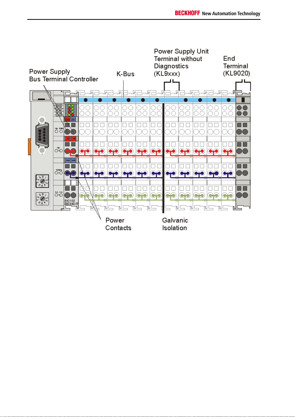
The Principle of the Bus Terminal
8 Fieldbus Components
Page 11

Safety Instructions
The Beckhoff Bus Terminal System
Up to 64 Bus Terminals each having 2 I/O channels for each signal form
The Bus Terminal system is the universal interface between a fieldbus system and the sensor / actuator level. A unit
consists of a Bus Coupler as the head station, and up to 64 electronic series terminals, the last one being an end
terminal. For each technical signal form, terminals are available each having two I/O channels, and these can be
mixed in any order. All the terminal types have the same mechanical construction, so that difficulties of planning and
design are minimized. The height and depth match the dimensions of compact terminal boxes.
Decentralized wiring of each I/O level
Fieldbus technology allows more compact forms of controller to be used. The I/O level does not have to be brought to
the controller. The sensors and actuators can be wired decentrally, using minimum cable lengths. The controller can
be installed at any location within the plant.
Industrial PCs as controllers
The use of an Industrial PC as the controller means that the operating and observing element can be implemented in
the controller’s hardware. The controller can therefore be located at an operating panel, in a control room, or at some
similar place. The Bus Terminals form the decentralized input/output level of the controller in the control cabinet and
the subsidiary terminal boxes. The power sector of the plant is also controlled over the bus system in addition to the
sensor/actuator level. The Bus Terminal replaces the conventional series terminal as the wiring level in the control
cabinet. The control cabinet can have smaller dimensions.
Bus Couplers for all usual bus systems
The Beckhoff Bus Terminal system unites the advantages of a bus system with the possibilities of the compact series
terminal. Bus Terminals can be driven within all the usual bus systems, thus reducing the controller parts count. The
Bus Terminals then behave like conventional connections for that bus system. All the performance features of the
particular bus system are supported.
Assembly on standardized C mounting rails
The easy, space-saving, assembly on a standardized C-rail, and the direct wiring of actuators and sensors, without
cross-connections between the terminals, standardizes the installation. The consistent labelling scheme also
contributes.
The small physical size and the great flexibility of the Bus Terminal system allows it to be used wherever a series
terminal is also used. Every type of connection, such as analog, digital, serial or the direct connection of sensors can
be implemented.
Modularity
The modular assembly of the terminal strip with Bus Terminals of various functions limits the number of unused
channels to a maximum of one per function. The presence of two channels in one terminal is the optimum
compromise of unused channels and the cost of each channel. The possibility of electrical isolation through potential
feed terminals also helps to keep the number of unused channels low.
Display of the channel state
The integrated LEDs show the state of the channel at a location close to the sensors and actuators.
K-Bus
The K-Bus is the data path within a terminal strip. The K-Bus is led through from the Bus Coupler through all the
terminals via six contacts on the terminals’ side walls. The end terminal terminates the K-Bus. The user does not
have to learn anything about the function of the K-Bus or about the internal workings of the terminals and the Bus
Coupler. Many software tools that can be supplied make project planning, configuration and operation easy.
Fieldbus Components 9
Page 12

Safety Instructions
Potential feed terminals for isolated groups
The operating voltage is passed on to following terminals via three power contacts. You can divide the terminal strip
into arbitrary isolated groups by means of potential feed terminals. The potential feed terminals play no part in the
control of the terminals, and can be inserted at any locations within the terminal strip.
Up to 64 terminals can be used within one terminal strip. This count does include potential feed terminals, but not the
end terminal.
Bus Couplers for various fieldbus systems
Various Bus Couplers can be used to couple the electronic terminal strip quickly and easily to different fieldbus
systems. It is also possible to convert to another fieldbus system at a later time. The bus coupler performs all the
monitoring and control tasks that are necessary for operation of the connected Bus Terminals. The operation and
configuration of the Bus Terminals is carried out exclusively by the Bus Coupler. Nevertheless, the parameters that
have been set are stored in each Bus Terminal, and are retained in the event of voltage drop-out. Fieldbus, K-Bus
and I/O level are electrically isolated.
If the exchange of data over the fieldbus is prone to errors or fails for a period of time, register contents (such as
counter states) are retained, digital outputs are cleared, and analog outputs take a value that can be configured for
each output when commissioning. The default setting for analog outputs is 0 V or 0 mA. Digital outputs return in the
inactive state. The timeout periods for the Bus Couplers correspond to the usual settings for the fieldbus system.
When converting to a different bus system it is necessary to bear in mind the need to change the timeout periods if
the bus cycle time is longer.
The interfaces
A Bus Coupler has six different methods of connection. These interfaces are designed as plug connectors and as
spring-loaded terminals.
10 Fieldbus Components
Page 13
Safety Instructions
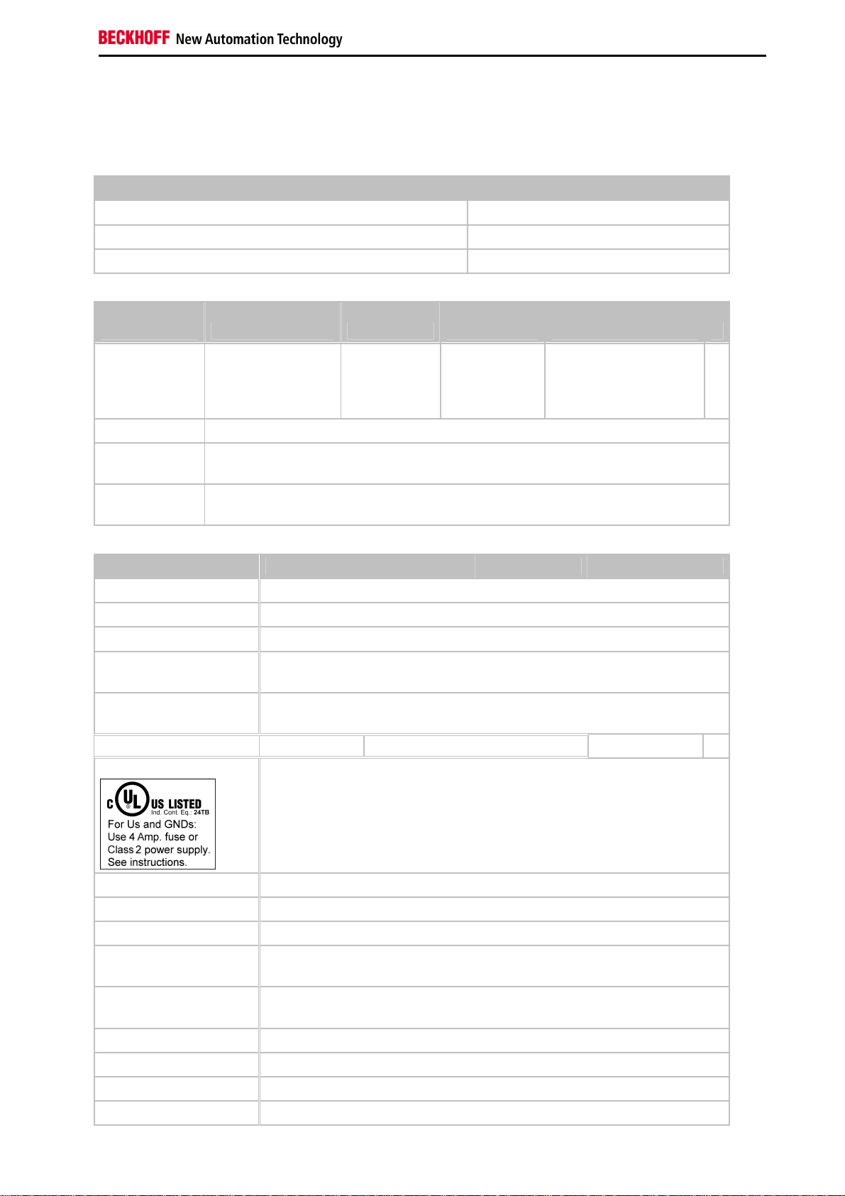
Technical Data
Technical Data - BCxx50
Technical data BCxx5x
Processor 16 bit micro-controller
Diagnostic LEDs 2 x power supply, 2 x K-Bus
Configuration and programming software TwinCAT PLC
Fieldbus
interface BC3150 BC5150 BC5250 BC8150 -
Fieldbus PROFIBUS DP CANopen DeviceNet - Serial ADS
- KS8000 Protocol
- ModbusRTU
- ModbusASCII
Interfaces
Serial interface COM1 (RS232 for configuration and programming, automatic baud rate detection
9600/19200/38400/57600 baud)
Terminal Bus (KBus)
Technical data BC3150 BC5150 BC5250 BC8150 -
Digital peripheral signals 2040 inputs/outputs
Analog peripheral signals 1024 inputs/outputs
Configuration possibility via TwinCAT or the controller
Maximum fieldbus byte
number
Maximum number of bytes
- PLC
Bus connection D-sub, 9-pin Open Style Connector, 5 pin D-sub, 9-pin -
64 (255 with K-Bus extension)
depending on fieldbus
2048 bytes of input data, 2048 bytes of output data
-
Power supply (Us)
Input current (Us) 60 mA + (total K-Bus current)/4
Starting current approx. 2.5 x continuous current
K-Bus current (5 V) maximum 1000 mA
Power contact voltage
(Up)
Power contact current load
(Up)
Recommended fuse (Up) ≤ 10 A
Dielectric strength 500 V
Weight approx. 100 g
Dimensions (W x H x D) approx. 44 mm x 100 mm x 68 mm
24 VDC (-15%/+20%) To meet the UL requirements use a 4 A fuse or a power
supply that has to satisfy NEC class 2!
maximum 24 VDC
maximum 10 A
(power contact / supply voltage / fieldbus)
rms
Fieldbus Components 11
Page 14

Safety Instructions
Technical data BC3150 BC5150 BC5250 BC8150 -
Operating temperature 0°C... +55°C
Storage temperature -25°C... +85°C
Relative humidity 95 % no condensation
Vibration / shock resistance conforms to EN 60068-2-6 / EN 60068-2-27, EN 60068-2-29
EMC resistance burst / ESD conforms to EN 61000-6-2 / EN 61000-6-4
Installation pos. Variable
Protection class IP20
12 Fieldbus Components
Page 15
Safety Instructions
Technical Data - PROFIBUS DP
System data PROFIBUS (BC3150)
Number of I/O modules 126 (BC3150 max. 99 devices)
Number of I/O points depending on controller
Data transfer medium shielded copper cable 2 x 0.25 mm², cable type A according to EN 50170
Segment length up to 1200 m
Number of segments 3
Data transfer rate up to 12 MBaud
Topology RS485 line, optical fiber ring
Transmission time approx. 0.5 ms with 10 stations for 32 bits input/output at 12 MBaud
Fieldbus Components 13
Page 16

Safety Instructions
Technical Data - PLC
PLC data BCxx5x
Programmability via serial programming interface or via the fieldbus
Program memory 48 kbyte
Source code memory 128 kbyte
Data memory 32 kbyte
Remanent flags 2 kbyte
PLC cycle time Approx. 3,0 ms for 1000 IL commands (without I/O cycle)
Programming languages IEC 6-1131-3 (IL, LD, FBD, ST, SFC)
Run time 1 PLC task
Online Change Yes
Up/Down Load Code Yes/Yes
14 Fieldbus Components
Page 17
Safety Instructions
3. Mounting and Wiring
Mounting
Dimensions
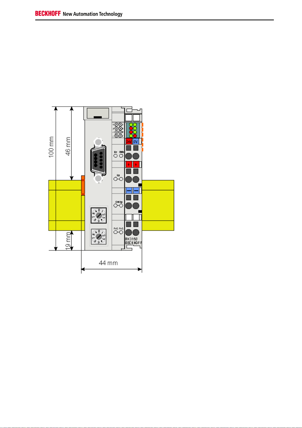
The Beckhoff Bus Terminal system is characterized by low physical volume and high modularity. When planning a
project it must be assumed that at least one Bus Coupler and a number of Bus Terminals will be used. The
mechanical dimensions of the Bus Couplers are independent of the fieldbus system.
Fig. 1.0 BCxx50
The total width of the fieldbus station is the width of the Bus Coupler/Bus Terminal Controller plus the width of the
Bus Terminals being used (incl. KL9010 bus end terminal). Depending on design, the Bus Terminals are 12 or 24 mm
wide. The height is 100 mm.
The BCxx50 series Bus Terminal Controllers are 68 mm deep.
Fieldbus Components 15
Page 18
Safety Instructions
Installation
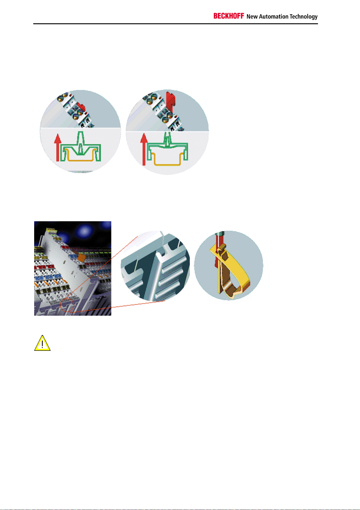
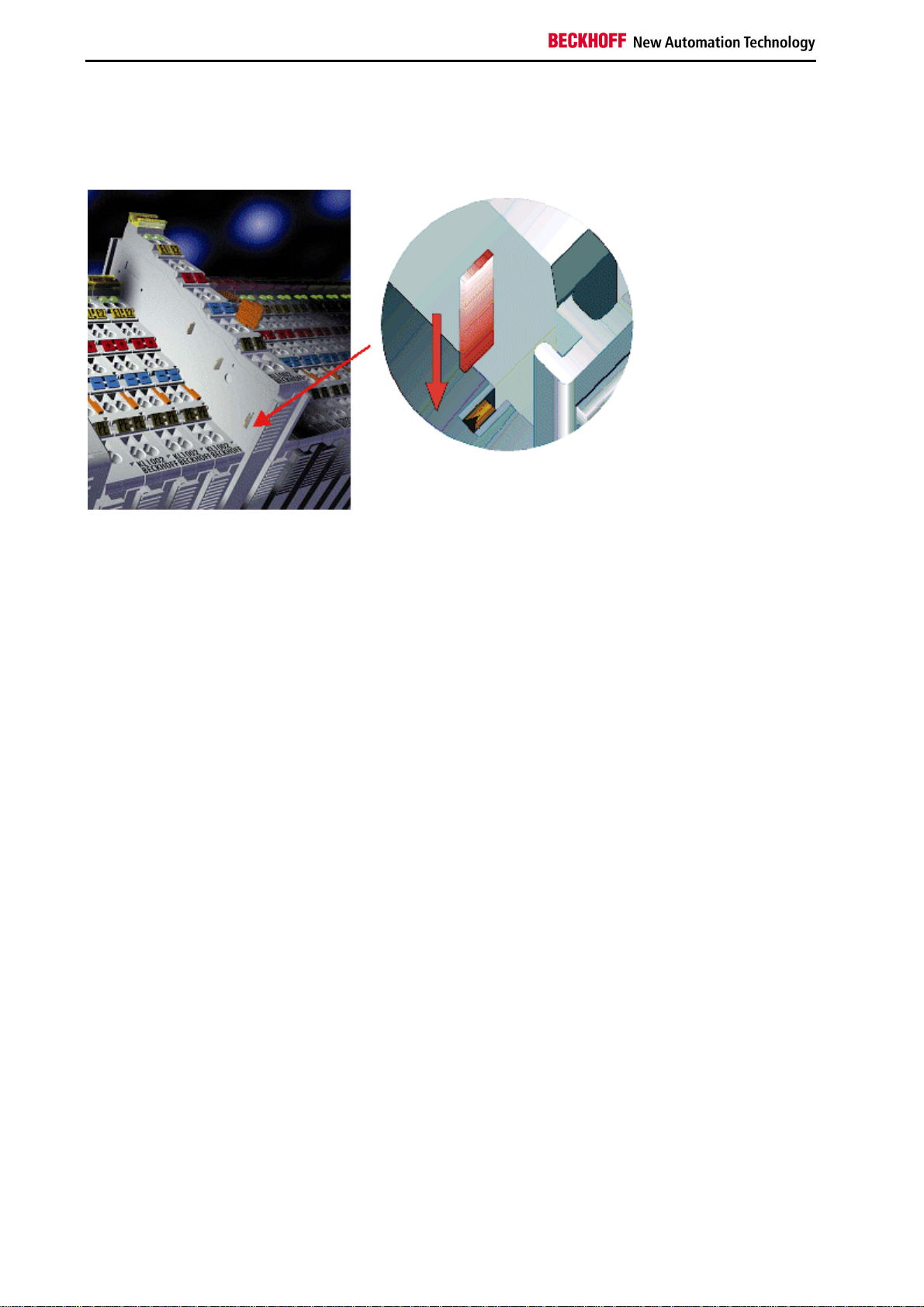
The Bus Coupler and all the Bus Terminals can be clipped, with a light press, onto a 35 mm mounting rail. A locking
mechanism prevents the individual housings from being pulled off again. For removal from the mounting rail the
orange colored tension strap releases the latching mechanism, allowing the housing to be pulled off the rail without
any force.
Up to 64 Bus Terminals can be attached to the Bus Coupler on the right hand side. When plugging the components
together, be sure to assemble the housings with groove and tongue against each other. A properly working
connection can not be made by pushing the housings together on the mounting rail. When correctly assembled, no
significant gap can be seen between the attached housings.
Insertion and removal of Bus Terminals is only permitted when switched off. The
Warning
electronics in the Bus Terminals and in the Bus Coupler are protected to a large measure
against damage, but incorrect function and damage cannot be ruled out if they are plugged
in under power.
The right hand part of the Bus Coupler can be compared to a Bus Terminal. Eight connections at the top enable the
connection with solid or fine wires from 0.08 mm² to 2.5 mm². The connection is implemented with the aid of a spring
device. The spring-loaded terminal is opened with a screwdriver or rod, by exerting gentle pressure in the opening
above the terminal. The wire can be inserted into the terminal without any force. The terminal closes automatically
when the pressure is released, holding the wire securely and permanently.
16 Fieldbus Components
Page 19
Safety Instructions
Wiring
Potential Groups, Insulation Testing and PE
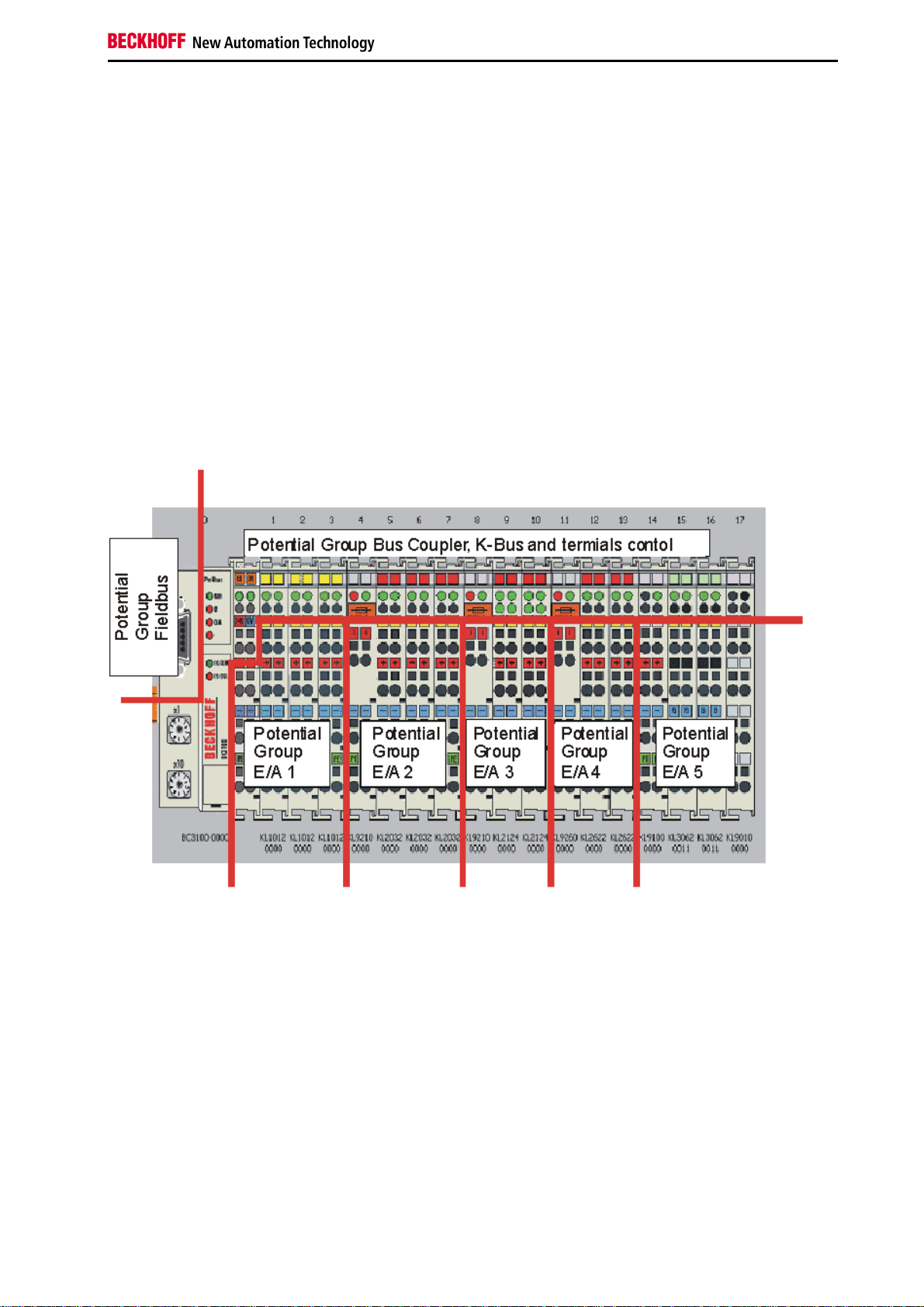
Potential groups
The Beckhoff Bus Terminals stations usually have three different potential groups:
•
The fieldbus interface is electrically isolated (except for individual Low Cost couplers) and forms the first potential group
•
Bus Coupler / Bus Terminal Controller logic, K-Bus and terminal logic form a second galvanically separated
potential group
•
The inputs and outputs are supplied via the power contacts and form further potential groups.
Groups of I/O terminals can be consolidated to further potential groups via potential supply terminals or separation
terminals.
Insulation testing
The connection between the Bus Coupler / Bus Terminal Controller and the Bus Terminals is automatically realized
by pushing the components together. The transfer of the data and the supply voltage for the intelligent electronics in
the Bus Terminals is performed by the K-Bus. The supply of the field electronics is performed through the power
contacts. Plugging together the power contacts creates a supply rail. Since some Bus Terminals (e.g. analog Bus
Terminals or 4-channel digital Bus Terminals) are not looped through these power contacts (or not completely) the
Bus Terminal contact assignments must be considered.
The potential feed terminals interrupt the power contacts, and represent the start of a new supply rail. The Bus
Coupler / Bus Terminal Controller can also be made use of to feed the power contacts.
Fieldbus Components 17
Page 20
Safety Instructions
PE power contacts
The power contact labelled PE can be used as a protective earth. For safety reasons this contact mates first when
plugging together, and can ground short-circuit currents of up to 125 A.
It should be noted that, for reasons of electromagnetic compatibility, the PE contacts are capacitively coupled to the
mounting rail. This can both lead to misleading results and to damaging the terminal during insulation testing (e.g.
breakdown of the insulation from a 230 V power consuming device to the PE conductor). The PE conductor to the
Bus Coupler / Bus Terminal Controller must be disconnected for the insulation testing. In order to uncouple further
feed locations for the purposes of testing, the feed terminals can be pulled at least 10 mm out from the connected
group of other terminals. In that case, the PE conductors do not have to be disconnected.
The PE power contact must not be used for other potentials.
18 Fieldbus Components
Page 21
Safety Instructions
Power supply
Bus Terminal Controller and Bus Terminal supply (Us)
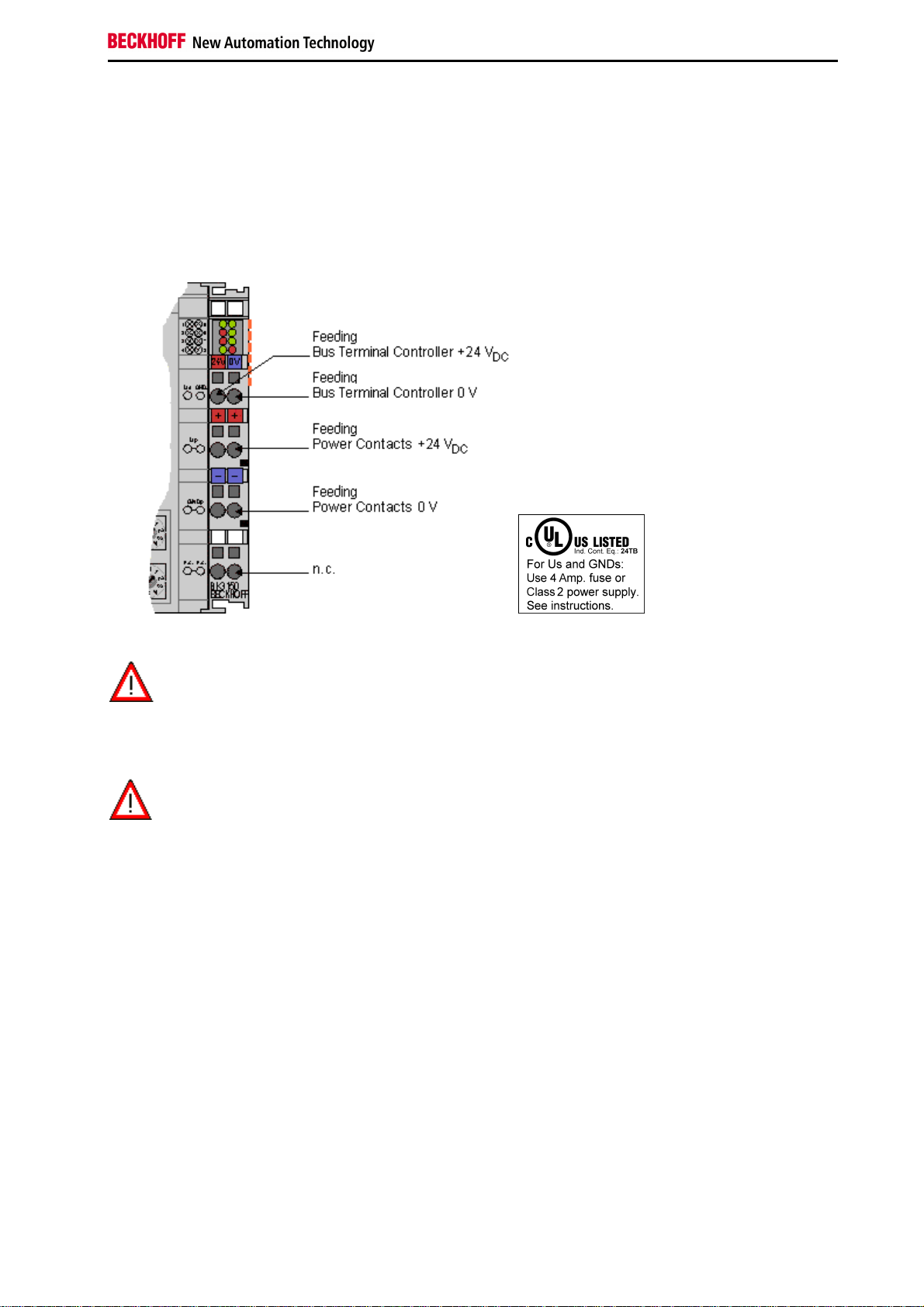
The Bus Terminal Controller requires a supply voltage of 24 VDC for its operation.
The connection is made by means of the upper spring-loaded terminals labelled 24 V and 0 V. This supply voltage
feeds the Bus Coupler / Bus Terminal Controller electronics and, over the K-Bus, the electronics of the Bus
Terminals. It is electrically separated from the potential of the field level.
UL requirements
For the compliance of the UL requirements Us should only be supplied
•
Danger
To meet the UL requirements, Us must not be connected to unlimited power sources!
Danger
by a 24 VDC supply voltage, supplied by an isolating source and protected by
means of a fuse (in accordance with UL248), rated maximum 4 Amp.
•
by a 24 VDC power source, that has to satisfy NEC class 2.
A NEC class 2 power supply shall not be connected in series or parallel with another (class 2) power source!
Power contacts supply (Up)
The bottom six connections with spring-loaded terminals can be used to feed the supply for the peripherals. The
spring-loaded terminals are joined in pairs to a power contact. The feed for the power contacts has no connection to
the voltage supply for the BC electronics.
The spring-loaded terminals are designed for wires with cross-sections between 0.08 mm2 and 2.5 mm2.
The assignment in pairs and the electrical connection between feed terminal contacts allows the connection wires to
be looped through to various terminal points. The current load from the power contact must not exceed 10 A for long
periods. The current carrying capacity between two spring-loaded terminals is identical to that of the connecting
wires.
Power contacts
On the right hand face of the Bus Terminal Controller there are three spring contacts for the power contact
connections. The spring contacts are hidden in slots so that they can not be accidentally touched. By attaching a Bus
Terminal the blade contacts on the left hand side of the Bus Terminal are connected to the spring contacts. The
tongue and groove guides on the top and bottom of the Bus Terminal Controllers and of the Bus Terminals
guarantees that the power contacts mate securely.
Fieldbus Components 19
Page 22
Safety Instructions
Programming cable
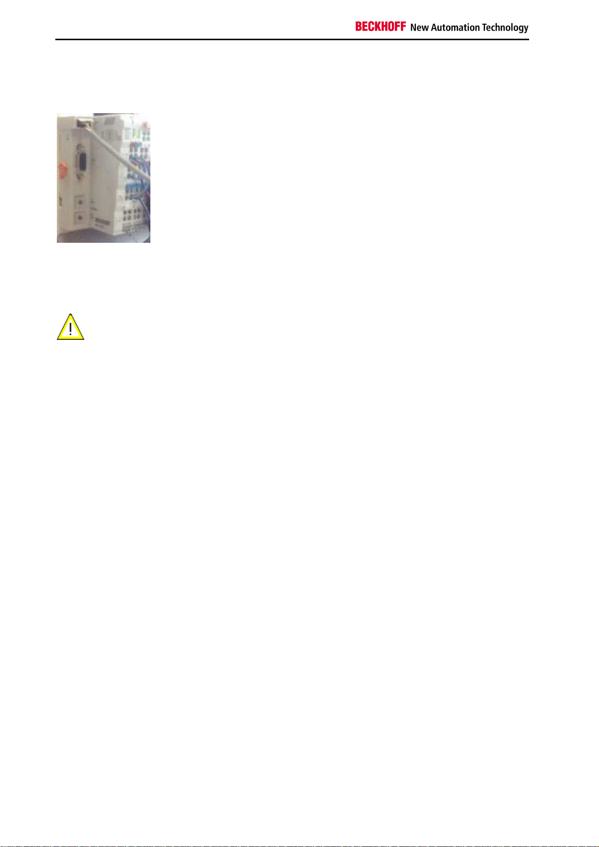
Use the KS2000-Z2 programming cable for serial programming of the Bus Terminal Controller. This cable is included
in the scope of supply of the KS2000 software, or it can be ordered separately (order number KS2000-Z2).
KS2000-Z2
The programming cable offers the option of programming the BCxx50 via the serial interface.
When the programming cable (between BCxx50 and PC) is connected, the ground
Warning
connection of the Bus Terminal controller must not be interrupted or disconnected, since
this may destroy the programming cable.
20 Fieldbus Components
Page 23
Safety Instructions
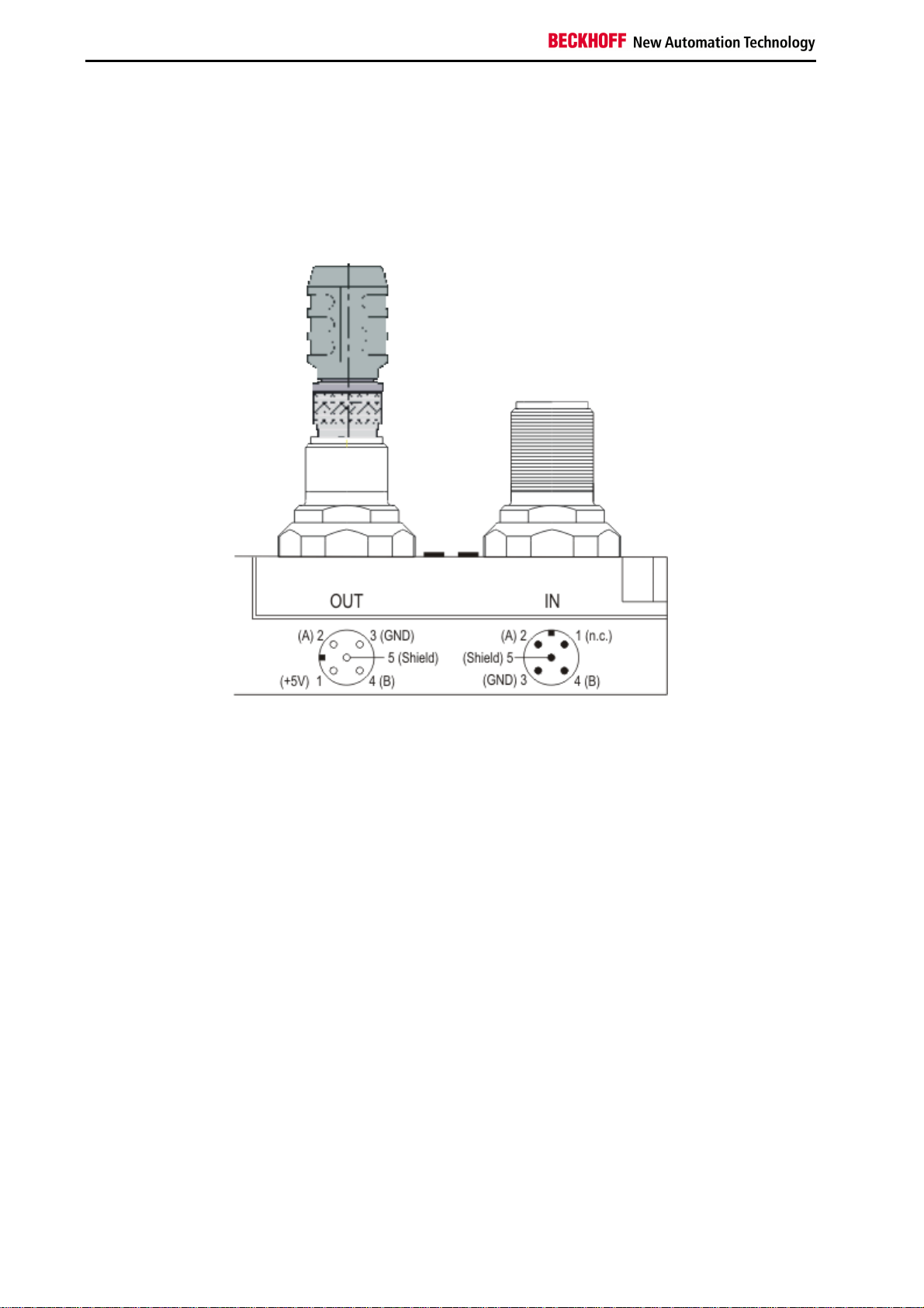
PROFIBUS Connection
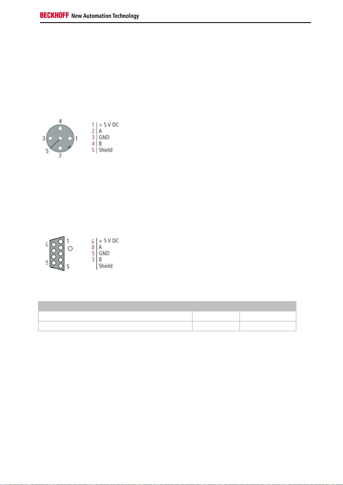
M12 circular connector
The M12 socket is inverse coded, and has five pins. Pin 1 is 5 VDC and 3 is GND for the active termination resistor.
These must never be misused for other functions, as this can lead to destruction of the device. Pin 2 and pin 4 are
the Profibus signals. These must never be swapped over, as this will prevent communication. Pin 5 is the shield, and
this is capacitatively coupled to the Fieldbus Box chassis.
M12 socket pin assignment
Nine pole D-Sub
Pin 6 is 5 VDC und Pin 5 is GND for the active termination resistor. These must never be misused for other functions,
as this can lead to destruction of the device. Pin 3 and pin 8 are the Profibus signals. These must never be swapped
over, as this will prevent communication. Shield is connected to the D-Sub housing that is coupled with lowresistance to the mounting rail.
D-Sub socket pin assignment
Profibus conductor colors
Profibus conductors M12 D-Sub
B red Pin 4 Pin 3
A green Pin 2 Pin 8
Fieldbus Components 21
Page 24
Safety Instructions
Connection of FieldbusBox modules
The connection of the Fieldbus Box modules is done direct or via a T-piece (or Y-piece).
The B318 series does have a male and female connector, that means no external T-piece is required. The supply
voltage (+5VDC) for the termination resistor is only supplied via the female M12 connector. The termination resistor
ZS1000-1610 is only available with male connector, therefore the incoming PROFIBUS line should end in a female
connector.
Two T-pieces are available:
•
ZS1031-2600 with +5VDC on male and female connector for the termination resistor
•
ZS1031-2610 with +5VDC only on the female connector
22 Fieldbus Components
Page 25

Safety Instructions
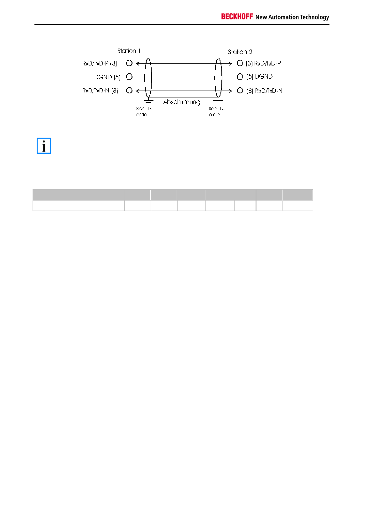
PROFIBUS Cabling
Physical aspects of the data transmission are defined in the Profibus standard (see Profibus layer 1: Physical Layer).
The types of area where a fieldbus system can be used is largely determined by the choice of the transmission
medium and the physical bus interface. In addition to the requirements for transmission security, the expense and
work involved in acquiring and installing the bus cable is of crucial significance. The Profibus standard therefore
allows for a variety of implementations of the transmission technology while retaining a uniform bus protocol.
Cable-based transmission
This version, which accords with the American EIA RS-485 standard, was specified as a basic version for
applications in production engineering, building management and drive technology. A twisted copper cable with one
pair of conductors is used. Depending on the intended application area (EMC aspects should be considered) the
screening may be omitted.
Two types of conductor are available, with differing maximum conductor lengths (see the RS-485 table).
RS485 - Fundamental properties
RS-485 transmission according to the Profibus standard
Network topology Linear bus, active bus terminator at both ends, stubs are possible.
Medium Screened twisted cable, screening may be omitted, depending upon the
environmental conditions (EMC).
Number of stations 32 stations in each segment with no repeater. Can be extended to 127 stations
with repeater
Max. bus length without
repeater
Max. bus length with
repeater
Transmission speed
(adjustable in steps)
Plug connector 9-pin D-Sub connector for IP20
100 m at 12 MBit/s
200 m at 1500 KBit/s, up to 1.2 km at 93.75 KBit/s
Line amplifiers, or repeaters, can increase the bus length up to 10 km. The
number of repeaters possible is at least 3, and, depending on the manufacturer,
may be up to 10.
9.6 kBit/s; 19.2 kBit/s; 93.75 kBit/s; 187.5 kBit/s; 500 kBit/s; 1500 kBit/s; 12 MBit/s
M12 round connector for IP65/67
Cabling for Profibus DP and Profibus FMS
Note the special requirements on the data cable for baud rates greater than 1.5 MBaud. The correct cable is a basic
requirement for correct operation of the bus system. If a simple 1.5 Mbaud cable is used, reflections and excessive
attenuation can lead to some surprising phenomena. It is possible, for instance, for a connected Profibus station not
to achieve a connection, but for it to be included again when the neighboring station is disconnected. Or there may be
transmission errors when a specific bit pattern is transmitted. The result of this can be that when the equipment is not
operating, Profibus works without faults, but that there are apparently random bus errors after start-up. Reducing the
baud rate (< 93,75 kBaud) corrects this faulty behavior.
If reducing the baud rate does not correct the error, then in many cases this can indicate a wiring fault. The two data
lines maybe crossed over at one or more connectors, or the termination resistors may not be active, or they may be
active at the wrong locations.
Installation is made a great deal more straightforward if pre-assembled cables from
Note
BECKHOFF are used! Wiring errors are avoided, and commissioning is more rapidly
completed. The BECKHOFF range includes fieldbus cables, power supply cables, sensor
cables and accessories such as terminating resistors and T-pieces. Connectors and cables
for field assembly are nevertheless also available.
Fieldbus Components 23
Page 26
Safety Instructions
In systems with more than two stations all devices are wired in parallel. It is essential that
Note
the bus cables are terminated with resistors at the conductor ends in order to avoid
reflections and associated transmission problems.
Distances
The bus cable is specified in EN 50170. This yields the following lengths for a bus segment.
Baud rate in kbits/sec 9.6 19.2 93.75 187.5 500 1500 12000
Cable length in m 1200 1200 1200 1000 400 200 100
Stubs up to 1500 kbaud <6.6 m; at 12 Mbaud stub segments should not be used.
Bus segments
A bus segment consists of at most 32 devices. 126 devices are permitted in a Profibus network. Repeaters are
required to refresh the signal in order to achieve this number. Each repeater is counted as one device.
IP-Link is the subsidiary bus system for Fieldbus Boxes, whose topology is a ring structure. There is an IP master in
the coupler modules (IP230x-Bxxx or IP230x-Cxxx) to which up to 120 extension modules (IExxxx) may be
connected. The distance between two modules may not exceed 5 m. When planning and installing the modules,
remember that because of the ring structure the IP-Link master must be connected again to the last module.
Installation guidelines
When assembling the modules and laying the cables, observe the technical guidelines provided by the Profibus User
Organization (Profibus Nutzerorganisation e.V.) for Profibus DP/FMS (see www.profibus.com).
Checking the Profibus wiring
A Profibus cable (or a cable segment when using repeaters) can be checked with a few simple resistance
measurements. The cable should meanwhile be removed from all stations:
1. Resistance between A and B at the start of the lead: approx. 110 Ohm
2. Resistance between A and B at the end of the lead: approx. 110 Ohm
3. Resistance between A at the start and A at the end of the lead: approx. 0 Ohm
4. Resistance between B at the start and B at the end of the lead: approx. 0 Ohm
5. Resistance between screen at the start and screen at the end of the lead: approx. 0 Ohm
If these measurements are successful, the cable is okay. If, in spite of this, bus malfunctions still occur, this is usually
a result of EMC interference. Observe the installation notes from the Profibus User Organization (www.profibus.com).
24 Fieldbus Components
Page 27
Safety Instructions
4. Parameterization and Commissioning
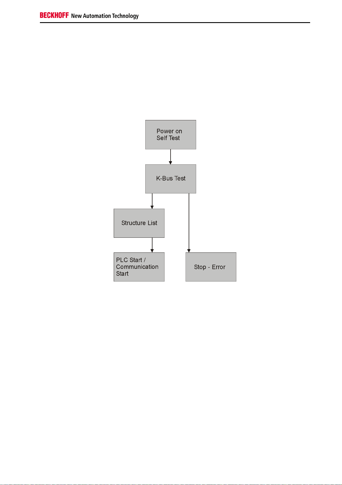
Start-up Behavior of the Bus Terminal Controller
After being switched on, the Bus Terminal Controller checks its state, configures the K-Bus, creates a structure list on
the basis of the inserted bus terminals and starts it's local PLC.
The I/O LEDs illuminate and flash as the Bus Coupler starts up. If there are no errors, the I/O LEDs should stop
flashing within about 2-3 seconds. In the case of an error, the flash code of the according LED depends on the error
type (see Diagnostic LEDs).
Fieldbus Components 25
Page 28
Safety Instructions
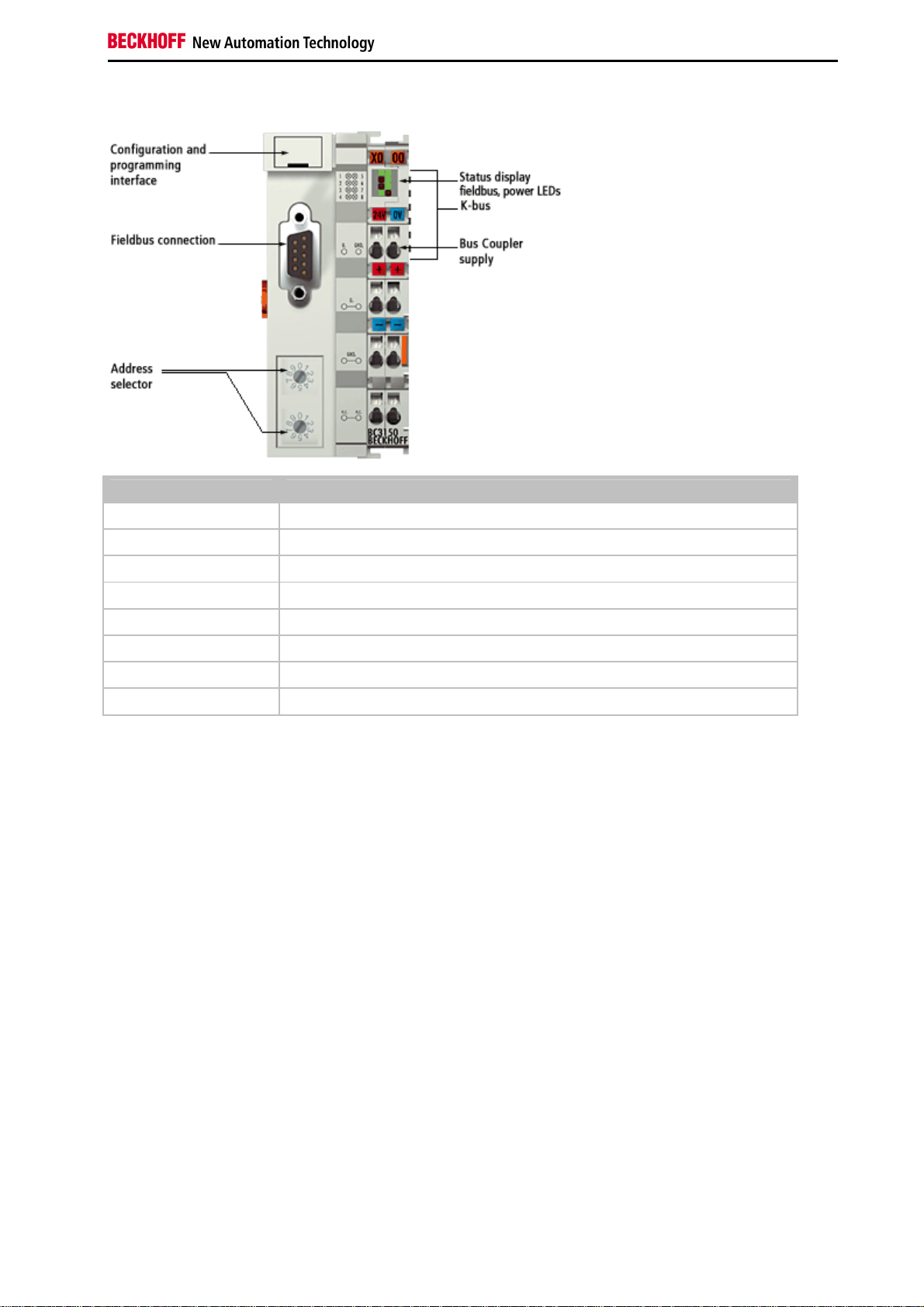
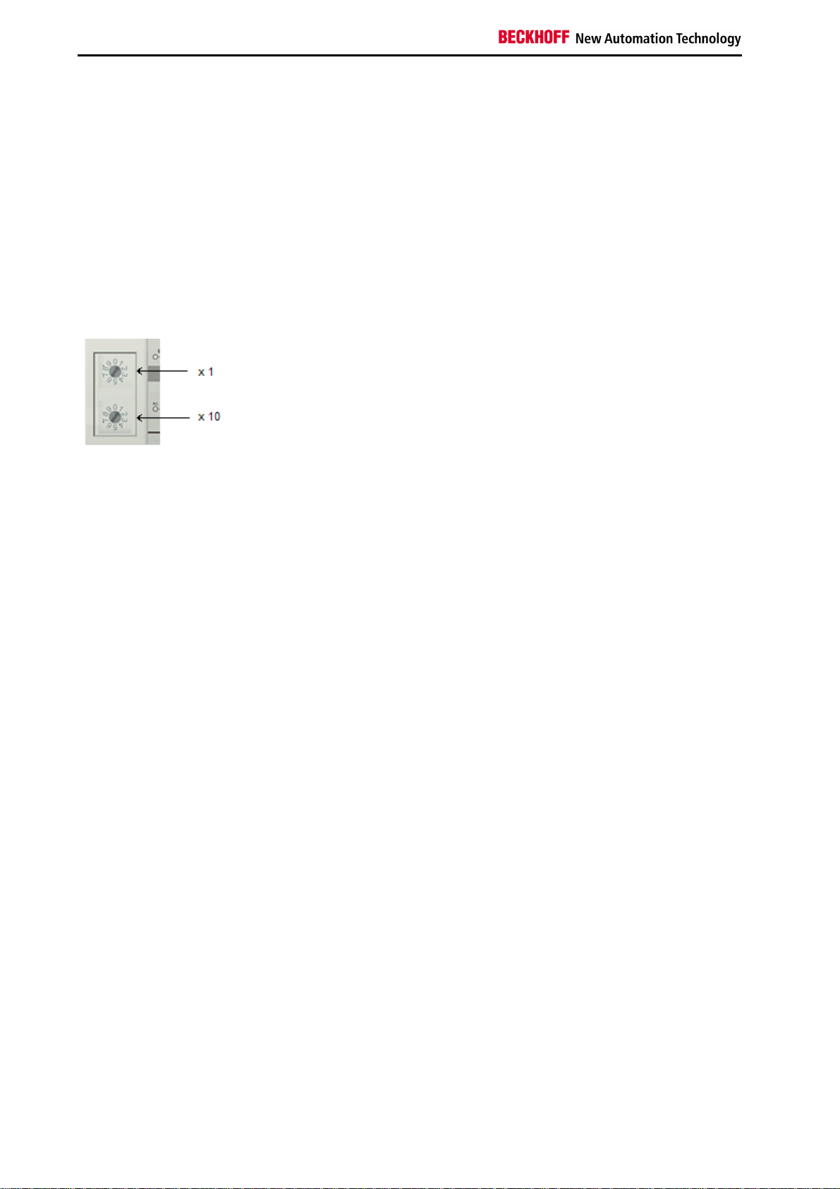
Setting the slave address
The address must be set via the two rotary selection switches. The default setting is 11. All addresses are permitted,
although each address may only occur once within the network. For changing an address the Bus Coupler must be
switched off. The switches can be set to the required position using a screwdriver. Ensure that the switches engage
correctly. The lower switch is the 10-multiplier, the upper switch is the 1-multiplier. The change in address is active as
soon as the module is switched on.
Example
You want to set address 34:
•
lower rotary selection switch Sx11: 3
•
upper rotary selection switch Sx10: 4
26 Fieldbus Components
Page 29

Safety Instructions
Configuration
Overview
Configuration types
DEFAULT-CONFIG
Bus Terminals are mapped in the order they are inserted, i.e. first the complex Bus Terminals followed by the digital
Bus Terminals.
The complex Bus Terminals are mapped as follows:
•
Word Alignment
•
complex representation
The fieldbus slave interface are the PLC variables. The PLC variables have addresses from %QB1000 and %IB1000.
TWINCAT-CONFIG
Bus Terminals and PLC variables can be linked freely in TWINCAT-CONFIG (TC-file required). The configuration is
transferred to the coupler via the System Manager and ADS.
The following is required for TwinCAT Config:
•
Via the fieldbus (PROFIBUS, CANopen, Ethernet)
PROFIBUS: (BC3150, BX3100)
- PC with FC310x from version 2.0 and TwinCAT 2.9 build 1000
- BX3100 with firmware from 0.28 with CIF60 or CP5412
- TwinCAT 2.9 build 946
(WARNING: only one ADS communication is permitted with the Hilscher cards, i.e. either System Manager
or PLC Control)
CANopen: (BC5150, BX5100)
PC with FC510x from version 1.76 or higher and TwinCAT 2.9 build 1030
DeviceNet: (BC5250, BX5200)
on request
Ethernet: (BX9000):
- TwinCAT 2.10 Build xxxx
•
Via serial ADS TwinCAT 2.9 build 1010 for NT4.0, 2000 or XP
- BX3100 version 1.00
- BX5100 version 1.00
- BX5200 version 1.10
- BX8000 version 1.00
- BC3150, BC5150, BC5250 Frimware B0
- BC8150 TwinCAT 2.10 Build 1244
The BX can be parameterised via the System Manager of the TwinCAT program.
•
Variable I/O mapping
•
Type-specific PROFIBUS data (only BC3150 or BX3100)
•
RTC (Real Time Clock) (only BX-controller)
•
SSB bus (Smart System Bus) (only BX-controller)
•
PLC settings
•
K-Bus settings
The configuration can be transferred to the BXxxxx or BCxx50 via fieldbus ADS protocol or with the serial ADS
protocol.
Fieldbus Components 27
Page 30

Safety Instructions
The TwinCAT configuration can be used to link variables, I/Os and data. The following is possible:
•
PLC - K-BUS
•
PLC - fieldbus (e.g. PROFIBUS slave interface)
•
K-Bus - fieldbus (only the BX-Controller)
In addition, the TwinCAT configuration can be used to parameterise special behaviour, for example whether data are
preserved or set to "0" in the event of a fieldbus error.
The real-time clock can be set via a tab in the system manager.
Individual steps
1. Setting the fieldbus address
2. Opening the system manager and creating a TC-file
3. Configuring fieldbus data in the TC-file
4. Saving the TC-file
5. Opening a new system manager, creating a PC file and reading in saved TC-file
6. Creating a link to a PLC task
7. Saving the configuration
8. Starting the TwinCAT system
9. Opening the system manager for the TC-file, completing the configuration and transferring it to the BXxxxx
or BCxx50
10. Transferring the program to the BXxxxx or BCxx50
11. Creating a boot project
28 Fieldbus Components
Page 31

Safety Instructions
Creating a BX File
For configuring the BX, a BX file has to be created in the System Manager. To simplify matters, files for the basic
units have already been prepared. Open the respective BX Controller via New from Template.
Select the associated BX Controller.
All BX Controller components are now available.
•
Fieldbus interface
•
K-Bus Interface
•
PLC Program
•
SSB (only BX-Controller)
Please refer to the relevant section for device configuration.
Fieldbus Components 29
Page 32

Safety Instructions
Downloading a BX Configuration
The configuration is transferred to the Bus Terminal Controller via ADS.
ADS serial (all BX and BCxx50-Controller)
Enter the serial ADS connection, as described in section Serial ADS.
ADS fieldbus (only BX3100, BX5100, BX9000, BC3150, BC5150)
A prerequisite is that TwinCAT operates as the master and data exchange is active, i.e. physical and PROFIBUS,
CANopen configuration must be completed, and data must be exchanged from the master (FC310x, FC510x) to the
Bus Terminal Controller.
Selecting the target system
Select the BXxx00 to which you wish to upload the configuration. F8 opens the dialog for downloading the associated
device.
Select the associated Bus Terminal Controller.
The device state (BX) is displayed at the bottom right of the System Manager.
In Config Mode / FreeRun the configuration can now be transferred to the BX. If the BX is in Stop Mode, ADS
communication has not yet been activated. In this case, the configuration cannot be downloaded.
30 Fieldbus Components
Page 33

Safety Instructions
For activating the configuration select Ctrl+Shift+F4 or Activate Configuration.
The current configuration is uploaded to the BX. The display will show Store Config, and the BUS and I/O LED will
flash. After the configuration has been transferred successfully to the BX, the BX display should show TwinCAT
Config. The required program can now be transferred to the BX (program download via the fieldbus).
Fieldbus Components 31
Page 34

Safety Instructions
Uploading a BX Configuration
The configuration is transferred to the Bus Terminal Controller via ADS.
ADS serial (all BX and BCxx50-Controller)
Enter the serial ADS connection, as described in section Serial ADS.
ADS fieldbus (only BX3100, BX5100, BX9000, BC3150, BC5150)
A prerequisite is that TwinCAT operates as the master and data exchange is active, i.e. physical and PROFIBUS,
CANopen configuration must be completed, and data must be exchanged from the master (FC310x, FC510x) to the
Bus Terminal Controller.
Selecting the target system
Select the BXxx00/BCxx50 to which you wish to upload the configuration. F8 opens the dialog for downloading the
associated device.
Select the associated Bus Terminal Controller.
The device state (Bus Terminal Controller) is displayed at the bottom right of the System Manager.
32 Fieldbus Components
Page 35

Safety Instructions
Click on the red folder. The TwinCAT configuration will now be uploaded.
Fieldbus Components 33
Page 36

Safety Instructions
Bus Terminal Controller resources
The system manager indicates the memory resources used by the Bus Terminal Controller in the Resources tab of
the Bus Terminal Controller.
Mapping code
The mapping code is required for calculating the TwinCAT configuration (see Fig. 1). The percentages are added up.
In the example from Fig 1., 8% of the memory is used for the mapping calculation.
Fig. 1: Memory for code mapping
Data memory mapping
Data memory for mapping. The values are to be considered individually, i.e. each value can be up to 100%.
Fig. 2 Data memory mapping
34 Fieldbus Components
Page 37
Safety Instructions
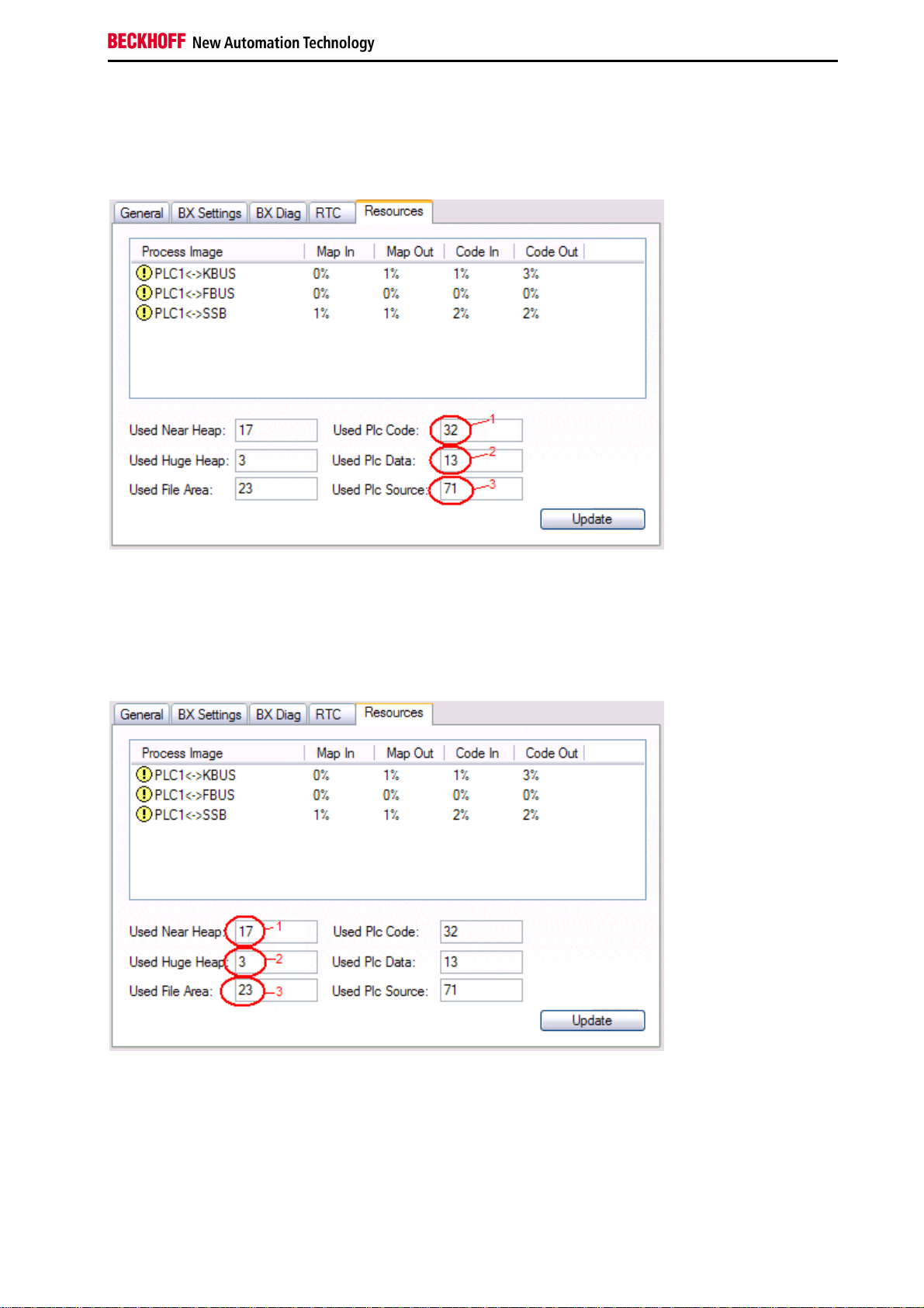
Used code and data memory
Fig. 3 (1): "Used PLC code" in %.
Fig. 3 (2): "Used PLC data" in % of memory.
Fig. 3 (3): "Used PLC Source" in %.
Fig. 3: Code and data memory
Other memory
Fig.4 (1): "Used Near Heap" is required for the COM interface and SSB. % values.
Fig.4 (2): "Used Huge Heap" is required for ADS communication. % values. This value should be less than 30 %.
Fig.4 (3): "Used file Area" is required for TwinCAT configuration, the TSM file and 16kB flash access. % values.
Fig.4: Other memory
Fieldbus Components 35
Page 38

Safety Instructions
ADS via Serial
ADS Connection via Serial Interface
(from firmware version 1.xx or 0.99x - Bus Terminal Controller of BX series and at all BCxx50)
for TwinCAT 2.9 build 1010 (TwinCAT level PLC, NC or NCI)
To ensure correct function of the serial ADS connection, only one connection is permitted.
Note
After successful configuration via the System Manager, close the System Manager before
starting programming.
Initializing the ADS connection
Enter the Bus Terminal Controller in the remote connection under TwinCAT. Click on the TwinCAT icon and open
the feature menu. The following settings can be made under the >AMS Remote< tab.
Remote Name: Any
AMS Net Id: 1.1.1.1.1.1 (Default)
Address: Com Port: baud rate, parity, data bits, stop bits
Transport: "COM port" is to be chosen here
No strings can be entered under address when the dialog is first called (see above). Enter
Note
Communication starts as soon as TwinCAT is in Config or RUN mode. The COM port is not closed until TwinCAT
stops, after which it is available for other programs.
name, AMS Net ID, and transport type and close the dialog. When the dialog is called
again you can enter your COM port.
Reading AMS Net ID
The AMS Net ID can be read from the menu via the display of the Bus Terminal Controller of the BX series.
AMS
1.1.1.1.1.1
Note
If the Bus Terminal Controller has been addressed via a fieldbus ADS connection before
the serial ADS connection was used, the System Manager will automatically have changed
the AMS Net ID. Read the current ADS number.
AMS Net ID
36 Fieldbus Components
Page 39

Safety Instructions
PROFIBUS
PROFIBUS Settings
The PROFIBUS-relevant settings are made in the DP slaves tab.
Reaction to PROFIBUS Error
In the event of a PROFIBUS error (e.g. PROFIBUS cable is pulled), the output data of the PROFIBUS master are
retained unchanged or set to 0 (depending on the parameterization). From the BX3100 perspective these are input
data that are transferred from the PROFIBUS master to the BX3100.
DP data format
The PROFIBUS data can be transferred in Intel or Motorola format.
Checking the DP configuration data
The configuration data can
•
not be checked at all;
•
checked for correct length; or
•
checked for length and content
Fieldbus Components 37
Page 40

Safety Instructions
Master Configuration
Basic Device File (GSD)
All field devices with PROFIBUS slave interface are described via the GSD file. The BC3150 is a PROFIBUS DP
slave. For data exchange, the GSD file has to be inserted in the master configuration tool. The maximum length of
input and output data 128 bytes in each direction.
Download GSD file (German):
Download GSD file (English):
The GSD file can describe the following data types:
Variable Length
Integer 8 1 byte
UnInteger 8 1 byte
Integer 16 2 bytes
UnInteger 16 2 bytes
Integer 32 4 bytes
UnInteger 32 4 bytes
Float 32 4 bytes
Data types that are not listed, e.g. BOOL variables, can be described via the length. For this purpose, the GSD file
includes configuration data starting with a byte and ending with 64 words.
38 Fieldbus Components
Page 41

Safety Instructions
Creating a TwinCAT PC File
DEFAULT CONFIG
DEFAULT-CONFIG contains the PROFIBUS data from the address %IB1000 input and %QB1000. The data length
depends on the number of configured PROFIBUS data. A maximum of 244 bytes of input date and 244 bytes of
output data can be parameterised. No further settings are required for this configuration type.
Fig.1: Inserting BX3100.
Inserting the BX3100 in a PROFIBUS master via the System Manager
Select your PROFIBUS master PC card in the System Manager and right-click on your PROFIBUS master card. The
PROFIBUS devices will then be offered for selection, among them a BX3100. Select this and confirm with OK.
Opening an existing BX file
If you wish to work with the DEFAULT-CONFIG, interrupt the process at this point (see Creating PROFIBUS data in
DEFAULT-CONFIG). Otherwise select your configured BX file. If no such file exists, you have to create one (Creating
a BX file). Once you have selected your BX file, all required PROFIBUS data are copied automatically into your
project from this file. You now have to create a link to your task and set the PROFIBUS address. The configuration
can then be saved and the TwinCAT system started.
Fieldbus Components 39
Page 42

Safety Instructions
Creating PROFIBUS data in DEFAULT-CONFIG
The PROFIBUS data can now be created. Various variables are available:
- Integer 8 bit
- Integer 16 bit
- Integer 32 bit
- UnInteger 8 bit
- UnInteger 16 bit
- UnInteger 32 bit
- FLOAT 32 bit
They have to match the variable types currently projected in the BX.
Data sizes from 1 byte to 64 words are available.
Fig.2: Creating PROFIBUS data
ADS Communication has to be selected for preparing the configuration. If the configuration data are to be transferred
via the fieldbus, data communication has to be active, i.e. the BX must exchange data with the controller.
40 Fieldbus Components
Page 43

Safety Instructions
Variable Mapping - PROFIBUS DP
Creating the PROFIBUS data.
Fig. 1: Creating PROFIBUS data
For linking with the PLC project, the PLC program must be read in. Add your PLC program under PLC Configuration.
The PLC variables can now be linked with the fieldbus variables.
Ensure that the maximum permissible number of PROFIBUS data is not exceeded
Note
(BX3100: max. 244 bytes inputs and 244 bytes outputs)!
(BC3150: max. 128 bytes inputs and 128 bytes outputs)!
Fieldbus Components 41
Page 44

Safety Instructions
BC3150 at 3rd party controller
SIEMENS S7
Configuration - Siemens S7 Controller
Inserting the images
In order to assign an image to the devices in the Siemens software, the following graphics must be copied into the
Step7\S7Data\ncbmp directory.
BC3150d.DIB
BC3150n.DIB
BC3150s.DIB
Inserting the GSD files
•
Go to Extras\Install new GSD in the hardware catalog for your Step7.
•
Select the directory in which the BECKHOFF GSD is located, and import the files.
•
You will then find them in the hardware catalog under Profibus DP\Other field devices\I/O.
42 Fieldbus Components
Page 45

Safety Instructions
Configuration: Siemens S7 Controller with BX3100
BX3100 parameter data
Fig. 1: Settings
Fieldbus Components 43
Page 46

Safety Instructions
BX3100 module configuration
Example 1
1 x BX3100
Fig. 2: Example for entering individual bytes. Note: Each individual byte requires one byte of ConfigData.
44 Fieldbus Components
Page 47

Safety Instructions
Fig. 3: Example for entering associated bytes.
Fieldbus Components 45
Page 48

Safety Instructions
K-Bus
K-Bus
BX Settings tab
Check Terminals during Start-up
When a boot project is created, the current Bus Terminal configuration is stored. The connected Bus Terminals are
checked when the BX is restarted. If this option is selected, the Bus Terminal Controller will not commence data
exchange. The PLC project will not be started.
Auto K-Bus Reset
After correction of a K-Bus fault, the Bus Terminal Controller will automatically re-commence data exchange.
Ensure that the outputs are reactivated immediately and that analog outputs retain their
Warning
Clear Outputs on Breakpoint
If break points are set in PLC Control, the K-Bus is no longer processed, i.e. the outputs are set to a safe state (zero).
K-Bus Sync Mode
Writing and reading of the Bus Terminals can occur synchronous with Task1, Task2 or the fieldbus.
K-Bus Re-Trigger
If the processor is busy dealing with the PLC project or the SSB, the K-Bus cannot be processed for a certain amount
of time. This leads to triggering of the Bus Terminal watchdog and dropping of the outputs. The Bus Terminal
Controller is set to re-trigger the K-Bus watchdog 3 times after 85 ms respectively. The K-Bus watchdog would then
be activated.
K-Bus Re-Trigger 0: 100 ms
K-Bus Re-Trigger 1: 2 x 85 ms = 70 ms
K-Bus Re-Trigger 2: 3 x 85 ms = 255 ms
K-Bus Re-Trigger 3: 4 x 85 ms = 340 ms
programmed value, if this is not dealt with in your PLC project.
Reaction on K-Bus Error
In the event of a K-Bus error, the K-Bus inputs are set to "0" or retain their last state.
Response on PLC-Stop
The user can set the behavior of the fieldbus output data in the event of the PLC project being stopped. The master
will use these data as input data. In the event of a PLC stop, the data can be set to "0" or remain unchanged.
46 Fieldbus Components
Page 49

Safety Instructions
BX Diag tab
Display of cycle time for task 1, task 2, K-Bus, fieldbus processing and SSB overhead.
Factory Settings - the Bus Terminal Controller is set back to its delivery state. These settings are reactivated via
Restart System or by switching the system off and on again (display shows DEFAULT-CONFIG).
K-Bus variables
PLCInterface: Not supported (only included for moving CX or BX projects)
KBus-State: see Diagnostics
Fieldbus Components 47
Page 50

Safety Instructions
PLC
Inserting a PLC project
For variable mapping, configuration has to be specified in the system manager. This is where the link between PLC
and hardware is specified. The variables can process and link bit, byte, word or data structures. Automatic
addressing via the System Manager is possible, but should be checked for offset.
A valid project has to be compiled and saved in PLC Control. These data are saved as a *.tpy file. For inserting a
PLC project, right-click on PLC - Configuration. Select your current PLC project.
Link the PLC variable with the hardware (e.g. digital Bus Terminal).
Once all links have been created, activate the configuration Actions/Activate Configuration (Ctrl+Shift+F4) and start
TwinCAT Set/Reset TwinCAT to Run Mode. Ensure that the correct target system is selected (bottom right in the
System Manager window).
48 Fieldbus Components
Page 51

Safety Instructions
Measuring the PLC Cycle Time
The task time is set in PLC Control. The default setting is 20 ms.
In the default setting, the PLC program is called every 20 ms, as long as the general cycle time is less than 20 ms.
The cycle time can be measured in the System Manager in order to determine your system load. To ensure troublefree operation, the set task time should be 20 to 30 % higher than the measured cycle time. A precise cycle time
breakdown can be found under K-Bus tab description.
Fieldbus Components 49
Page 52

Safety Instructions
KS2000
KS2000
The KS2000 software can provide assistance for the configuration or diagnosis of the connected Bus Terminals. The
KS2000 software cannot be used for parameterization or configuration of Bus Terminal Controller of BX series and
BCxx50. The TwinCAT System Manager has to be used for the settings.
The COM 1 interface features automatic baud rate detection between 9.6 and 56.4 kBaud*.
Note
The BXxxxx Controller is supported from version 4.3.14.
Note
50 Fieldbus Components
Page 53

Safety Instructions
5. Programming
BCxx50 PLC features
Description Value
Data memory 32 kbyte
Program memory 48 kbyte minus task-configuration minus POUs during online change
Source code memory 128 kbyte
RETAIN 2 kbyte
INPUT 2 kbyte
OUTPUT 2 kbyte
FLAG 4 kbyte
Max. variable size 16 kbyte
Max. POUs Limited by memory
Fieldbus Components 51
Page 54

Safety Instructions
TwinCAT PLC
The Beckhoff TwinCAT Software System turns any compatible PC into a real-time controller with a multi-PLC system,
NC axis control, programming environment and operating station. The TwinCAT programming environment is also
used for programming the BC/BX. If you have TwinCAT PLC (Windows NT4/2000/XP) installed, you can use the
fieldbus connection or the serial port for downloading and debugging software. If you are programming with TwinCAT
BC (also compatible with Windows 95/98/ME), the connection to the BC is made exclusively via the serial port.
TwinCAT I/O or TwinCAT PLC can also be used as the Ethernet Master (host), in order to exchange process data
with the Bus Terminal Controller. TwinCAT provides you with the System Manager as a configuration tool, as well as
the drivers and the ADS protocol.
Bus Terminal Controller of BX series and BCxx50
These 2nd-generation Bus Terminal Controllers are configured with the TwinCAT System Manager and programmed
with TwinCAT PLC Control. TwinCAT PLC has to be installed (Windows NT4, Windows 2000, Windows XP) for these
couplers.
Minimum requirement: TwinCAT from Version 2.9 build 940
Programming and program transfer
•
via the serial interface
•
via the fieldbus interface (only at Bus Terminal Controllers for PROFIBUS, CANopen and Ethernet)
Online Change
The Bus Terminal Controller of BX series and BCxx50 supports online change. This means that the PLC program is
replaced with a new program without interrupting the program. The switch-over to the new program occurs after the
task is completed. This means that two versions of the PLC program have to be stored. 512 kB are available, which
therefore have to be divided by 2, leaving 256 kB for the actual program. In addition, several kB are required for task
configuration etc. During an online change, dynamic data are stored in memory. Should a program approach the
memory limit (program size greater than 240 kB), the online change may no longer work, even though the program
may still be written to the BX after "Rebuild all".
When is online change not available?
Online change is not available under certain conditions
•
Inserting of a new library
•
Change in task setting
•
"Rebuild all"
•
Controller memory limit is almost reached (PLC program greater than 90%)
52 Fieldbus Components
Page 55

Safety Instructions
TwinCAT PLC error codes
Error type Description
PLC compiler error Maximum number of POUs (...) exceeded
PLC compiler error Out of global data memory ...
Error POUs
For each block one POU (process object unit) is created. 256 blocks are available by default.
If libraries are integrated this value may be insufficient. In this case, the number of POUs should be increased.
To this end, open
the controller settings in the PLC Control under Projects/Options.
Changing these settings will deactivate online changes.
Fieldbus Components 53
Page 56

Safety Instructions
Global memory error
2 x 16 kB of data are available by default. If large data quantities are to be used, this range should be increased. A
maximum of 14 data segments are possible for the BX.
54 Fieldbus Components
Page 57

Safety Instructions
Remanent data
2 kB of remanent data are available for the BX controller. These data are declared as VAR RETAIN in PLC Control:
Example:
VAR RETAIN
Test :BOOL;
Count :INT;
END_VAR
Retain data are located between VAR RETAIN and END_VAR. These data are stored in a NOVRAM and are
consistent across the whole 2 kB range. The RETAIN data are stored in the NOVRAM after each cycle. For 2 kB
approx. 2 ms are required (for 1 kB approx. 1 ms). The variables can be configured locally or globally. Variables are
located (%I...,%Q.., %M...) are not use as a Retain data.
VAR_RETAIN should not be used in function blocks. All FB data are copied into the retain
Note
Note
memory. This leads to an unnecessary increase in cycle time, and the retain memory is
filled with unnecessary data.
Variables, they have an address (%I...,%Q.., %M...), are not allowed to declare as a retain
variables.
Example for remanent data in the function block
Because all the data in a function block will be saved if even only one remanent bit is included, this should be
avoided if at all possible. A programming example can be found below.
Function block Test (no program code required - in ST a semicolon is sufficient)
FUNCTION_BLOCK Test
VAR_INPUT
END_VAR
VAR_OUTPUT
END_VAR
VAR
END_VAR
VAR_IN_OUT
Counter :INT;
END_VAR
MAIN program
PROGRAM MAIN
VAR
fb_Test:Test;
END_VAR
VAR RETAIN
iCounter1:INT;
END_VAR
fb_Test(Counter:=iCounter1);
Fieldbus Components 55
Page 58

Safety Instructions
Allocated Flags
4 kB of allocated flags are available. They can be used to assign different variable types to the same address, e.g. for
converting strings to bytes. Data can also be placed here that can be read or written via ADS by the controller.
The BX Controllers do not save the allocated variables as remanent data.
Note
Reading/writing of allocated flags via ADS
The flags may also be read via the controller and ADS. In PROFIBUS, the DPV-1 services are used for this purpose,
in CANopen SDO communication is used.
The AmsNetId can be taken from the System Manager, or it can be displayed in the BX menu.
The PLC port number is 800.
Index group Meaning Index offset (value range)
0x4020 Flag (only BXxxx0) 0..4096
Example
BX program
VAR
Flag_01 AT %MB0: WORD;
END_VAR
TwinCAT PC/CX Master Programm
VAR
fbADRSREAD: ADSREAD;
Flag_M: WORD;
END_VAR
fbADRSREAD(
NETID:='172.16.3.0.2.3' , (* AMSNetId BX *)
PORT:=800 , (* 800 - PLC *)
IDXGRP:=16#4020 , (* 0x4020hex flags *)
IDXOFFS:=0 , (* byte offset *)
LEN:=2 , (* Lenght byte *)
DESTADDR:=ADR(Merker) ,
READ:=TRUE ,
TMOUT:=t#1s );
IF NOT fbADRSREAD.BUSY THEN
fbADRSREAD(READ:=FALSE);
END_IF
56 Fieldbus Components
Page 59

Safety Instructions
Local process image in delivery state
The process image of the BX controller consists of an input, output and flag area. In addition, there are unallocated
data without fixed address. They are created without specifying an address. For this type of variable, 256 kbyte (48
kbyte BCxx50) of memory are available on the BX Controller. The maximum size of a variable or structure (array) is
16 kbyte. For the allocated data 2048 bytes of input data and 2048 bytes of output data are available. The BX has 4
kbyte of memory for the allocated flag area. In the delivery state (default configuration) of the BX, fixed addresses are
allocated for all connected Bus Terminals. The data for PROFIBUS communication start from address offset 1000
The length of the PROFIBUS data depends on the number of configured data. The maximum length is 244 bytes
(BX3100) / 128 bytes (BC3150).
Inputs Outputs
Bus Terminal %IB0 ... Bus Terminal %QB0 ...
PROFIBUS data (PLC variable) %IB1000 ... PROFIBUS data (PLC variables) %QB1000 ...
... %IB2047 Maximal ... %QB2047 Maximal
dec
Addressing of the connected Bus Terminals
The default setting is for all the connected Bus Terminals to be assigned to the local process image. Mapping within
the Bus Terminal Controller is carried out according to the following rule:
First come all the complex Bus Terminals, in whatever sequence they are physically inserted, followed by the digital
Bus Terminals which are padded to a whole byte. The default mapping of the complex Bus Terminals is:
.
•
complete evaluation
•
Intel format
•
Word alignment
Example structure
Bus Terminal Controller: 1 x BXxxxx/BCxx50
Position 1: 1 x KL1012
Position 2: 1 x KL1104
Position 3: 1 x KL2012
Position 4: 1 x KL2034
Position 5: 1 x KL1501
Position 6: 1 x KL3002
Position 7: 1 x KL4002
Position 8: 1 x KL6001
Position 9: 1 x KL9010
Process image
Bus Terminal Position Input image Output image
KL1501 5 %IB0...%IB5 %QB0...%QB5
KL3002 6 %IB6...%IB13 %QB6...%QB13
KL4002 7 %IB14...%IB21 %QB14...%QB21
KL6001 8 %IB22...%IB29 %QB22...%QB29
KL1012 1 %IX30.0..30.1 KL1104 2 %IX30.1..30.5 KL2012 3 - %QX30.0..30.1
KL2034 4 - %QX30.2..30.5
KL9010 9 - -
Fieldbus Components 57
Page 60

Safety Instructions
If you do not know the address of the Bus Terminals that you have assigned to the local
Note
PLC (BC/BXxx00):
Perform your hardware configuration in the System Manager. After you have entered all the
Bus Terminals and PLC variables, click with the right mouse button on the BC/BXxx00 in
the hardware tree, and select the menu item Export variables information.... A file is saved,
and this file can be inserted in the System Manager under Project - Import. Now you will
have the entry TwinCAT import under the global variables, and you will find here all the
variables that you have assigned to the local PLC (BC/BXxx00).
58 Fieldbus Components
Page 61

Safety Instructions
Mapping of the Bus Terminals
The precise assignment of the byte-oriented Bus Terminals may be found in the configuration guide for the particular
bus terminal. This documentation is available on the Beckhoff CD Products & Solutions or on the Internet under
http://www.beckhoff.com.
Byte oriented Bus Terminals Bit oriented Bus Terminals
KL1501 KL10xx, KL11xx, KL12xx, KL17xx
KL25xx KL20xx, KL21xx, KL22xx, KL26xx, KL27xx
KL3xxx
KL4xxx
KL5xxx
KL6xxx
KL8xxx
KL9110, KL9160, KL9210, KL9260
Fieldbus Components 59
Page 62

Safety Instructions
Local process image in the TwinCAT configuration
The TwinCAT configuration (TwinCAT CONFIG) enables free mapping between PROFIBUS / K-Bus / PLC variables.
Variables can be linked independent of their address via the System Manager.
In the TwinCAT configuration, all Bus Terminals have fixed addresses. If a Bus Terminal is inserted, the whole
address range may be shifted. Many data are unnecessary and take up valuable address memory space. The
TwinCAT configuration rectifies this disadvantage. Allocated variables can be linked freely with a Bus Terminal.
Parameterization is carried out in the System Manager, and the configuration is then transferred to the BX (see
TwinCAT configuration).
60 Fieldbus Components
Page 63

Safety Instructions
Creating a boot project
Approximately 250 kB of flash are available.
For creating a boot project
•
on the Bus Terminal Controller of BX-Series app. 250 kByte of flash are available
•
on the Bus Terminal Controller of BCxx50-Series app. 48 kByte of flash are available
PLC Control
After logging in, a boot project can be created in TwinCAT PLC Control.
•
Opening a PLC project
•
Selecting the target system (or selection the serial interface)
•
BX/BCxx50 login
•
Creating the boot project (Online\Create boot project)
Once a valid boot project is present on the BX/BCxx50 controller, the green PLC LED is on.
At the Bus Terminal Controller of BX-Series the PLC LED will flash orange during the creation of the boot project. If
no boot project is available on the BX the PLC LED shines orange.
Deleting a boot project
A boot project can be deleted from the BX/BCxx50. The following steps must be followed:
•
Opening the project
•
BX/BCxx50 login
•
Deleting the boot project (Online\Delete boot project)
Once the boot project was deleted, the PLC LED will be orange.
After an online change, the boot project is still the old project. To use the current project
Note
(after the online change) as the boot project, the boot project has to be recreated.
Bypassing the start of the boot project*
At the Bus Terminal Controller of BX-Series the start up of an existing boot project can be avoided by pressing the
Navi switch during booting. This will not delete the boot project. The project can still be used when the controller is
switched on again.
* from version 0.85
Fieldbus Components 61
Page 64

Safety Instructions
Communication between TwinCAT and BX/BCxx50
It makes sense to define a data structure for transferring data between TwinCAT and Bus Terminal Controller. Please
note the following to account for the differences in data management on the two systems.
•
If two different data types are sent in sequence (e.g. byte and INT), the following variable is set to the next
even address offset
•
Boolean variables should never be allocated individually within a structure, since they would invariably occupy 1 byte. Boolean expressions should always be masked in a byte or word.
Example 1: Structure on the BX and on the PC
Variable BX memory PC memory (TwinCAT)
Byte %..B0 %..B0
INT (1) %..B2 %..B1
INT (2) %..B4 %..B3
Because the first byte is followed by a different variable type (INT), it was set to the next free even address in the
BX/BCxx50. In order to achieve the same data structure on both systems, a dummy byte has to be inserted in the PC
project (see example 2).
Example 2: Structure on the BX and on the PC with identical memory allocation
PC memory
Variable BX memory
Byte %..B0 %..B0
Byte
(Dummy)
INT (1) %..B2 %..B2
INT (2) %..B4 %..B4
Data structure
Type PB_Data
STRUCT
wVar_1:WORD;
iValue_1:INT;
iValue_2:INT;
iValue_3:INT;
END_STRUCT
END_TYPE
Creating a variable structure
VAR_Global
strData_Out AT %QB1000:PB_Data; (*PLC Variables *)
bInput_01 AT %IX0.0:BOOL; (* Input from a terminal *)
END_VAR
%..B1 (not necessarily required, since the system deals with this itself if the
variable does not exist)
(TwinCAT)
%..B1
Small programming example
strData_Out.wVar_1.0:=bInput_01;
A mixed data structure should not contain any Real values. If it does, the High and Low
Note
Note
word must be swapped in the BX/BCxx50or in the TwinCAT master project. It is better to
use an array of Real values or to transfer the Real values individually.
It is also possible to transfer larger fieldbus data blocks, in order to leave a reserve for your
structure. Disadvantage: These reserves are then transferred with each fieldbus telegram,
causing additional load for the fieldbus communication.
62 Fieldbus Components
Page 65

Safety Instructions
Up- and downloading of programs
The Bus Terminal Controller has 256 kB of memory for the source code. It can be used for storing the program, the
task configuration, and the libraries. Should the memory be insufficient, the source code may be stored without task
configuration and libraries. This takes up significant less memory space!
General Settings
The timing of the source code download to the target system can be specified via Edit/Options.
Fieldbus Components 63
Page 66

Safety Instructions
Downloading a program
The source code can be transferred to the target system on request. This requires the user to be logged in with his
program. Under Online/Sourcecode download the program code can now be transferred to the Bus Terminal
Controller.
After a short delay, a window will open that indicates the download progress.
64 Fieldbus Components
Page 67

Safety Instructions
Uploading a program
For uploading the program code again, open a new file in PLC Control. Then click on the PLC button.
Select the data transfer route. For the Bus Terminal Controller
- BCxx50 or BX via AMS, if they are connected via the fieldbus with the BX, or
- BCxx50 or BX via serial, if they are connected via the serial interface.
Then select the device and confirm with OK.
The source code will now be uploaded.
Fieldbus Components 65
Page 68

Safety Instructions
Password
You can protect your project with a password (in PLC Control Project/Options/Passwords).
66 Fieldbus Components
Page 69

Safety Instructions
Libraries
Libraries overview
The TwinCAT Automation Software offers various libraries for the BCxx50 series Bus Terminal Controllers (Bus
Coupler with PLC functionality) (see BECKHOFF information system).
Download
The libraries are also included in this documentation. For extracting the libraries, click on the disk icon with the left
mouse button and copy the libraries into the directory TwinCAT\PLC\LIB.
•
Standard
•
TcSystemBCxx50 TcSystemBCxx50 requires the TcBaseBCxx50 library.
•
TcBaseBCxx50
•
ChrAscBX.lbx
Always use the latest libraries in conjunction with the latest BC firmware. If you update the
Note
firmware of your Bus Terminal Controller, please also update the libraries. Copy the new
libraries into the LIB folder, remove them from your project and re-insert them.
TcSystemBCxx50
Firmware
ADS Version
ADSREAD B0 B0 B1 B0 ADSWRITE B0 B0 B1 B0 ADSRDWRT B0 B0 B1 B0 ADSWRTCTL B0 B0 B1 B0 ADSRDSTATE B0 B0 B1 B0 ADSRDDEVINFO B0 B0 B1 B0 -
Bit Functions Version
CLEARBIT32 B0 B0 B1 B0 CSETBIT32 B0 B0 B1 B0 GETBIT32 B0 B0 B1 B0 -
BC3150 BC5150 BC5250 BC8150 -
Firmware
BC3150 BC5150 BC5250 BC8150 -
SETBIT32 B0 B0 B1 B0 -
Firmware
Controller Version
FB_BasicPID - B0 B0 B1 B0 -
- - - - - - -
File Access Version
FB_ReadFromFile - - - - FB_WriteToFile - - - - FB_ReadWriteFile - - - - -
BC3150 BC5150 BC5250 BC8150 -
Firmware
BC3150 BC5150 BC5250 BC8150 -
Fieldbus Components 67
Page 70

Safety Instructions
Firmware
Memory Functions Version
BC3150 BC5150 BC5250 BC8150 -
MEMCMP B0 B0 B1 B0 MEMCYP B0 B0 B1 B0 MEMMOVE B0 B0 B1 B0 MEMSET B0 B0 B1 B0 -
Firmware
NOVRAM Functions Version
BX3100 BX5100 BX5200 BX8000 -
- - - - - - -
Firmware
SFC Version
BC3150 BC5150 BC5250 BC8150 -
AnalyzeExpression - - - - AppendErrorString - - - - SFCActionControl - - - - -
Firmware
System / Time / TBus Version
BC3150 BC5150 BC5250 BC8150 -
DRAND B0 B0 B1 B0 SYSTEMTIME_TO_DT B0 B0 B1 B0 DT_TO_SYSTEMTIME B0 B0 B1 B0 GetSysTick B0 B0 B1 B0 PresetSysTick B0 B0 B1 B0 Reboot B0 B0 B1 B0 -
Firmware
Debug Version
BC3150 BC5150 BC5250 BC8150 -
F_ReadDebugTimer F_StartDebugTimer -
68 Fieldbus Components
Page 71

Safety Instructions
TcBaseBX
System Task Info
VAR_GLOBAL
SystemTaskInfo : SYSTEMTASKINFOTYPE;
END_VAR
System flags are implicitly declared variables. Using the Input Assistant, a variable SystemTaskInfoArr can be found
under system variables. This variable is a field with four structures of type SYTEMTASKINFOTYPE. The structure
definition can be found in the system library. The index in this field is the task ID.
Development environment Target system type PLC libraries to be linked
TwinCAT v2.9.0 BCxx50 Controller TcBaseBCxx50.lbx
Fieldbus Components 69
Page 72

Safety Instructions
System task info type
TYPE SYSTEMTASKINFOTYPE
STRUCT
active : BOOL;
taskName : STRING(16);
firstCycle : BOOL;
cycleTimeExceeded : BOOL;
cycleTime : UDINT;
lastExecTime : UDINT;
priority : BYTE;
cycleCount : UDINT;
END_STRUCT
END_TYPE
Key
active: This variable indicates whether the task is active.
taskName: the task name.
firstCycle: during the first PLC task cycle, this variable has the value TRUE.
cycleTimeExceeded: this variable indicates whether the set task cycle time was exceeded.
cycleTime : set task cycle time in multiples of 100 ns.
lastExecTime: cycle time required for the last cycle in multiples of 100 ns.
priority: set task priority.
cycleCount: cycle counter.
Development environment Target system type PLC libraries to be linked
TwinCAT v2.9.0 BCxx50 Controller TcBaseBCxx50.lbx
70 Fieldbus Components
Page 73

Safety Instructions
System Info
VAR_GLOBAL
SystemInfo : SYSTEMINFOTYPE;
END_VAR
System flags are implicitly declared variables. Using the Input Assistant, a variable System Info can be found under
system variables. The type SYSTEMINFOTYPE is declared in the system library. For accessing the variable, the
system library has to be integrated in the project.
Development environment Target system type PLC libraries to be linked
TwinCAT v2.9.0 BCxx50 Controller TcBaseBCxx50.lbx
Fieldbus Components 71
Page 74

Safety Instructions
System Info Type
TYPE SYSTEMINFOTYPE
STRUCT
runTimeNo : BYTE;
projectName : STRING(32);
numberOfTasks : BYTE;
onlineChangeCount : UINT;
bootDataFlags : BYTE;
systemStateFlags : WORD;
END_STRUCT
END_TYPE
Key
runTimeNo: specifies the number of the runtime system (1).
projectName: project name as STRING.
numberOfTasks: number of tasks contained in the runtime system (max. 1).
onlineChangeCount: number of online changes since the last complete download.
bootDataFlags: Reserved
systemStateFlags: Reserved
Development environment Target system type PLC libraries to be linked
TwinCAT v2.9.0 BCxx50 Controller TcBaseBCxx50.lbx
72 Fieldbus Components
Page 75

Safety Instructions
ADS
Local ADS Port Numbers
Port number Description
100
Reading and writing of registers and tables from the coupler and the complex Bus Terminals
dec
801
Local PLC process image
dec
Fieldbus Components 73
Page 76

Safety Instructions
ADS Services
Local process image task 1 port 801
Data can be read from and written to the local process image. If it is necessary for outputs to be written, it is
important to ensure that they are not used by the local PLC, because the local controller will overwrite these values.
The data is not associated with a watchdog, and therefore must not be used for outputs that would have to be
switched off in the event of a fault.
Index group Meaning Index offset (value range)
0xF020 Inputs 0...2047
0xF030 Outputs 0...2047
0x4020 Flags 0...4095
ADS services
AdsServerAdsState
Data type (read only) Meaning
String Start - the local PLC is running
Start - the local PLC is stopped
AdsServerDeviceState
Data type (read only) Meaning
INT 0 – Start - the local PLC is running
1 – Stop - the local PLC is stopped
AdsServerType
Data type (read only) Meaning
String BX PLC Server
Register port 100
The ADS port number in the Bus Terminal Controller for register communication is fixed, being set at 100.
Index offset (value range)
Index group
0 [READ ONLY] 0..127 0..255 Registers in the Bus Coupler
1-255 0-3 1-255 Register of the Bus Terminal
Note
Note
Hi-Word Low Word
Note when reading the register that the time out for the ADS block is set to a time longer
than 1 second.
Note when writing to the registers that the password is set (see the documentation for the
particular Bus Terminal).
Meaning
High word, table number of the Bus Coupler
Low word, register number of the table
High word, channel number
Low word, register number of the Bus Terminal
74 Fieldbus Components
Page 77

Safety Instructions
BX Debug Function
BX Debug Function - Overview
These functions can be used for measuring command execution times in a PLC project. The unit is a tick. One tick
corresponds to 5.12 µs.
Start Debug Timer function
Calling this function starts the timer. The return value is "0".
Read Debug Timer function
This function reads the timer value. The return value has to be multiplied with 5.12 µs.
Example
VAR
Timer_BX :WORD;
i :INT;
END_VAR
Program
F_STARTDEBUGTIMER();
For i:=0 to 1000 do
;
END_FOR
Timer_BX:=F_READDEBUGTIMER();
Fieldbus Components 75
Page 78

Safety Instructions
Program Transmission
Transmission via Serial Interface
Every Bus Terminal Controller can be programmed via the PC's RS232 interface.
Select the serial interface in TwinCAT PLC Control.
The settings for the serial interface, port number, baud rate etc. are found under Online/Communication parameters
in PLC Control.
The Bus Terminal Controller requires the following setting:
•
Baud Rate: 9600/19200/38400/57600 baud (automatic baud rate detection)
•
Stop bits: 1
•
Parity: even
Transmission via the serial interface and ADS
The Bus Terminal Controller can be programmed via the PC's RS232 interface. Before it can be used, the TwinCAT
has to be made aware of the Bus Terminal Controller (see serial ADS).
Select the ADS connection in TwinCAT PLC Control.
76 Fieldbus Components
Page 79

Safety Instructions
PLC Control can be accessed via Online/Communication Parameters....
Fieldbus Components 77
Page 80

Safety Instructions
Transmission via PROFIBUS
TwinCAT offers a facility for transferring the application program to the BC/BX via the fieldbus. The BC/BX can be
selected as the target system in PLC Control, after saving in the registry and restarting the TwinCAT system. The
TwinCAT-level TwinCAT PLC is necessary.
Minimum requirements:
•
FC310x with firmware from 2.0
•
TwinCAT 2.9 build 945
Initializing the BC/BX
The coupler must first be made known to the system before it can be selected in PLC Control.
Enter the Bus Terminal Controller in the System Manager, specify type, quantity and size of the fieldbus variables
and link them with a task. For the subsequent program download via PROFIBUS, the ADS interface has to be
activated in the ADS tab of the BC/BX. Save your settings and activate the configuration. Then start the TwinCAT
system and the cyclic task.
TwinCAT System Manager
PLC Control
When TwinCAT PLC Control is restarted, TwinCAT asks for the target platform, i.e. the device on which the user
program is later to run. TwinCAT offers two target platforms for the controller, the PC or the Bus Terminal Controller.
Two routes are available to you for transmission to the Bus Terminal Controller:
•
AMS for BCxx00 (Bus Terminal Controller without online change, one task)
•
AMS for BCxx50 and BX (Bus Terminal Controller with online change, two tasks)
•
BC serial - serial cable for communication via the RS232 interface of the PC and the programming interface
of the Bus Terminal Controller
78 Fieldbus Components
Page 81

Safety Instructions
After your program has been created, select the target system under the Online toolbar. TwinCAT must be running to
do this. In the example, this is the Ethernet card with Box 1 and the Runtime 1 of the Bus Terminal Controller.
Fieldbus Components 79
Page 82

Safety Instructions
Process Image
PROFIBUS process image
The BC3150 is a PROFIBUS slave device. A basic device file (GSD) is available for the configuration on the master
side, which has to be integrated in the respective master configuration software. The type and quantity of the data to
be transferred to the PROFIBUS master is specified on the slave side, i.e. in the BC3150 . The BC3150 can process
a maximum of 128 bytes of input data and 128 bytes of output data. Two configuration types are available.
No special configuration is required for the DEFAULT CONFIG. The PROFIBUS data start at a certain address offset.
The type and quantity of data is configured in the master.
TWINCAT CONFIG requires the TwinCAT System Manager. It can be used for byte-wise linking of PROFIBUS data
with PLC data, or for linking data from the K-Bus to the PROFIBUS directly.
The input data of the BC3150 are output data of the master, and output data of the BC3150 are input data of the
slave.
DEFAULT CONFIG
In DEFAULT CONFIG, all allocated variables with address 1000 or greater are transferred to the master. The type
and number of variables is configured on the master side.
Example
Var_1 AT %IB1000 :INT; a 2-byte output variable has to be configured on the master side.
Var_2 AT %IB1002 :DINT; a 4-byte output variable has to be configured on the master side.
The order of the variables on the master side must be adhered to. Address gaps are only permitted if they are
configured on the master side. Otherwise, addressing must be continuous from address 1000.
TWINCAT CONFIG
For the TwinCAT CONFIG, a configuration must be created via the System Manager. The System Manager is used
for specifying the type and number of variables and for linking the variables. The PROFIBUS data may therefore be
located anywhere in the permissible allocated process image.
Permissible process image:
INPUT %IB0 - %IB2047
OUTPUT %QB0 - %QB2047
80 Fieldbus Components
Page 83

Safety Instructions
6. PROFIBUS
System Introduction
Fieldbus Overview
Profibus is a manufacturer - independent, open fieldbus standard with a wide range of applications in manufacturing
and process automation. Manufacturer-independence and openness are guaranteed by the International standards
EN 50170 and EN 50254. Profibus allows devices from different manufacturers to communicate without the need for
specially adapted interfaces. Profibus is suitable both for fast, time-critical applications and for complex
communication tasks.
Profibus offers communication protocols of different functional levels: DP and FMS. According to the application, RS485, IEC 1158-2 or optical fiber are available as transmission techniques.
Profibus specifies the technical features of a serial fieldbus system with which distributed digital automation devices
can be networked together, from the field level up to the cell level. Profibus is a multi-master system, and therefore
permits common operation of a number of automation, engineering or visualization systems with their distributed
peripheral devices on one bus.
Profibus distinguishes the following device types:
Master devices determine the data traffic on the bus. A master may transmit messages without having received an
external request when it is in possession of the bus access authorization (token). Masters are also referred to as
active devices.
Slave devices are peripheral devices such as input/output devices, valves, drives, measuring transducers and the
Beckhoff Profibus slaves from the BK3xx0, BC3xx0, IPxxxx-B310, IL230x-B310 and IL230x-C310 series. They do not
receive any bus access authorization, so that they are only allowed to acknowledge messages that have been
received, or to send messages in response to a request from master. Slaves are referred to as passive devices. They
only require a small proportion of the bus protocol, which means that they can be implemented with little effort.
Profibus DP
Profibus DP is designed for efficient data exchange at the field level. The central automation devices such as
PLC/PCs or process control systems communicate here over a fast serial link with distributed field devices such as
I/O, drives, valves etc.. Data is primarily exchanged with these distributed devices cyclically. The communication
functions required for this are specified by the basic DP functions in accordance with EN 50170.
In addition to these basic functions, Profibus DP also offers extended acyclic communication services for such
purposes as parameterization and other operations. These are also supported by the Beckhoff Profibus slaves of the
IPxxxx-B310, IL230x-B310 and IL230x-C310 series. A central controller (master) cyclically reads the input
information from the slaves, and writes the output information cyclically to the slaves. The bus cycle time here should
be shorter than the central automation system's program cycle time, which lies around 10 ms in many applications.
A high data throughput is not in itself sufficient for successful use of a bus system. Ease of handling, good diagnostic
facilities and secure transmission technology are also of the utmost importance if the user’s demands are to be
satisfied. These properties are ideally combined in Profibus DP.
System configuration and device types
Profibus DP allows single master or multi-master systems to be implemented. This permits a high level of flexibility
in system configuration. A maximum of 126 devices (master or slaves) can be connected to one bus. A station
address between 0 and 99 can be chosen for the Beckhoff Profibus slaves from the IPxxxx-B310, IL230x- B310 and
IL230x-C310 series. The specifications for the system configuration contain the number of stations, the assignment of
the station addresses to the I/O addresses, data consistency of the I/O data and the format of the diagnostics
messages and the bus parameters being used. Every Profibus DP system consists of different device types.
Fieldbus Components 81
Page 84

Safety Instructions
Three types of device are distinguished:
DP master
class 1
(DPM1)
e.g. Beckhoff
PC master
card FC310x
DP master
class 2
(DPM2)
DP slave
e.g. Beckhoff
Bus Coupler
IPxxxx-B310
In single master systems only one master is active on the bus in the operating phase of the bus system. The PLC
controller is the central control element. The distributed slaves are coupled to the PLC controller via the transmission
medium. The shortest bus cycle time is achieved with this system configuration.
In a multi-master mode there is more than one master on the bus. They either form sub-systems that are
independent of one another, each consisting of one DPM1 and the associated slaves, or additional project design
and diagnostic devices. All the DP masters can read the input and output images of the slaves. Writing the outputs is
only possible for one DP master (the one assigned as DPM1 during the project design). Multi-master systems
achieve a medium bus cycle time. In time-critical applications, the increase in bus cycle time should be observed by
adding a diagnostic tool.
This involves a central controller that exchanges information cyclically with the distributed
stations (slaves) in a specified message cycle. Typical devices include, for instance,
programmable logic controllers (PLCs) or PCs.
Devices of this type are engineering, project design or operating devices. They are used for
commissioning, for servicing and diagnosis in order to configure the connected devices, to
evaluate measured values and parameters and to interrogate the status of devices.
A Profibus DP slave is a peripheral device (I/O, drive, measuring transducer etc.) that reads
input information and passes output information on to the peripherals. It is also possible to
have devices that only handle either input or output information. The quantity of input and
output information is device-dependent, and may not exceed 246 bytes of input data and
246 bytes of output data.
Basic device files (GSD)
In Profibus DP, the performance characteristics of devices are documented by the manufacturers and made available
to users in the form of a device data sheet and of a basic device file. The structure, content and coding of these basic
device files (GSD) is standardized. They make it easy to plan a project with any Profibus DP slaves using project
planning devices from a various manufacturers. The Profibus User Organization (Profibus Nutzer Organization PNO) archives this information for all manufacturers, and will provide information about the GSD from any
manufacturer on request. The GSD files are read by a Profibus master configuration software, and appropriate
adjustments are transferred to the Profibus master. Please see the appropriate software manual from the master
manufacturer for a description.
The Beckhoff GSD files may be obtained from the internet under www.beckhoff.com.
Diagnostic functions
The extensive diagnostic functions of Profibus DP allow rapid fault localization. Diagnosis of the Beckhoff Bus
Coupler is not activated in the default setting of the type file or the GSD file. The diagnostic messages are transmitted
over the bus and collated by the master.
They are divided into three levels:
Diagnosis type Description
Related to the
station
Related to the
module
Related to the
channel
The Beckhoff Profibus slaves from the IPxxxx-B310, IL230x-B310 and IL230x-C310 series support the Profibus DP
diagnostic functions. Assessment of the diagnostic data by means of the controller depends on the support for the
Profibus master. Please refer to the device manuals for the master interfaces for details of how to handle the
diagnosis.
Messages relating to the general readiness of a device for operation such as overtemperature or under-voltage
These messages indicate that diagnostic signals are pending within a specific I/O sub
range of the device (e.g. an 8 bit output module)
Here the cause of an error is related to a single input/output bit (channel), such as a
short circuit on output 2
82 Fieldbus Components
Page 85

Safety Instructions
Sync and Freeze Mode
In addition to the user data traffic related to the device, which is automatically dealt with by DPM1, a DP master has
the option of sending control commands to one DP slave, to a group of them or to all of them at the same time. These
control commands are transmitted as multicasts. These control commands can be used to specify the sync and
freeze operating modes, in order to synchronize the DP slave. They permit event-controlled synchronization of the
DP slaves.
The DP slaves start sync mode when they receive a sync control command from the assigned DP master. In this
operating mode, the outputs of all the addressed DP slaves are frozen at their current values. In the following user
data transmissions, the DP slaves store the output data, but the output states themselves nevertheless remain
unchanged. Only when the next sync control command is received from the master the stored output data is switched
through to the outputs. Sync operation is ended with an unsync control command.
A freeze control command similarly causes the addressed DP slaves to enter freeze mode. In this operating mode
the states of the inputs are frozen at their current value. The input data is only updated again when the DP master
has sent the next freeze control command to the devices concerned. Freeze operation is ended with an unfreeze
command.
System behavior
The system behavior is also standardized in Profibus DP, so that devices can to a large extent be interchanged. It is
largely determined by the operating condition of the DPM1. This can either be controlled locally, or over the bus by
the project design device.
The following three principal conditions are distinguished:
Operation
mode Description
Stop
Clear
Operate
The DPM1 sends its local status at a configurable time interval using a multicast command cyclically to all the DP
slaves that have been assigned to it. The reaction that the system has to the occurrence of an error during the
DPM1's data transfer phase, such as the failure of a DP slave, is specified in the Auto-Clear operating parameter. If
this parameter is set to True, then the DPM1 switches the outputs of all the associated DP slaves into a safe state as
soon as one DP slave is no longer ready for the transfer of user data. The DPM1 then switches into the Clear state. If
the parameter is False then the DPM1 remains in the operating state even after a fault, and the user can himself
specify the system's reaction.
There is no data traffic between the DPM1 and the DP slaves. The Bus Coupler only
addresses the Bus Terminals once after the power has been switched on (none of the I/O
LEDs are lit).
The DPM1 reads the input information from the DP slaves, and maintains the outputs of the
DP slaves in a safe state (depending on the reaction to fieldbus errors, the green I/O LED is lit
and the outputs are set).
The DPM1 is in a data transfer phase. In the course of cyclic data traffic the inputs of the DP
slaves are read and the output information is transmitted to the DP slaves (the green I/O LED
is lit).
Fieldbus Components 83
Page 86

Safety Instructions
Data traffic between the DPM1 and the DP slaves
The data traffic between the DPM1 and the DP slaves that have been assigned to it is automatically executed by the
DPM1 in a specified, continuously repeated sequence. The user specifies the assignment of a DP slave to the DPM1
when the bus system's project is being planned. Those DP slaves that are included in or excluded from the cyclic
user data traffic are also defined.
The data traffic between the DPM1 and the DP slaves is divided into the parameterization, configuration and data
transfer phases.
Before a DP slave is included in the data transfer phase, the DPM1 checks, in the parameterization and configuration
phase, whether the theoretical configuration that has been planned agrees with the actual configuration of devices.
The check requires the device type, the format and length information, as well as the number of inputs and outputs,
to be in agreement. The user is thus provided with reliable protection against errors in parameterization. In addition to
the transfer of user data, which is automatically carried out by the DPM1, it is possible to send new parameterization
data to the DP slaves at the user's request.
Protection mechanisms
In the context of distributed peripherals it is necessary, for reasons of safety and reliability, for the system to be given
extremely effective functions to protect against incorrect parameterization or the failure of the transmission
mechanisms. Profibus DP uses monitoring mechanisms in the DP Master and in the DP Slaves. They are
implemented in the form of time monitors. The monitoring interval is specified in when the DP system project is
planned.
Protection
mechanisms Description
At the DP
Master
At the DP
Slave
The DPM1 monitors the slave's transfer of user data with the Data_Control_Timer. An
individual monitoring timer is used for each assigned slave. The time monitor triggers if a
proper transfer of user data does not take place within the monitoring interval. In this case
the user is informed. If automatic error reaction is enabled (Auto_Clear = True) then the
DPM1 leaves the Operate state, switches the outputs of the assigned slaves into a safe
state, and then goes into the Clear operating mode.
The slave uses communication monitoring in order to detect errors of the master or in the
transmission segment. If data is not transferred with the assigned master within the
communication monitoring interval the slave switches the outputs into the safe state itself.
The slave inputs and outputs further require access protection in multi-master systems, to
ensure that direct access is only made from the authorized master. The slaves will make an
image of the inputs and outputs available to other masters, and this can be read by any
other master even if it does not have access authorization.
Ident number
Every DP slave and every DPM1 must have an individual identification number. This is required so that a DP master
can identify the types of the connected devices without any significant protocol overhead. The master compares the
identification numbers of the connected DP devices with the identification numbers in the project planning data
specified by DPM2. The transfer of user data only starts if the correct device types are connected to the bus at the
correct station addresses. This provides protection from project planning errors. Manufacturer-specific identification
numbers are issued by the Profibus User Organization (PNO). The PNO administers the identification numbers along
with the basic device data (GSD).
84 Fieldbus Components
Page 87

Safety Instructions
PROFIBUS DP
In PROFIBUS DP systems, a master (PLC, PC etc.) usually communicates with a large number of slaves (I/Os,
drives etc.). Only the master may here actively access the bus (send telegrams on its own initiative), while a DP slave
only sends telegrams when it is requested to do so by a master.
DP StartUp
Before the master and slave can cyclically exchange data, the parameter and configuration data is transmitted from
the master to the slaves during the DP StartUp phase. After the parameter and configuration data has been sent, the
master interrogates the slave's diagnostic data until the slave indicates that it is ready for data exchange. Depending
on the extent of the calculations that the slave must carry out after receiving the parameter and configuration data, it
can take up to a few seconds before it is ready for data exchange. For this reason the slave possesses the following
states:
Parameter data
The parameter data is sent from the master to the slave in the SetPrmLock request telegram. The SetPrmLock
response telegram does not contain any data, and therefore consists of a single byte, the short acknowledgement.
The parameter data consists of DP parameters (e.g. the setting of the DP watchdog or checking the IdentNumber
(unique to each DP device)), of DPV1-/DPV2 parameters and of application-specific parameters that only have to be
transmitted once during the StartUp. If an error is found in the parameter data, this is indicated in the diagnostic data,
and the slave either remains in or enters the WAIT-PRM state.
Configuration data
The configuration data is sent from the master to the slave in the ChkCfg request telegram. The ChkCfg response
telegram does not contain any data, and therefore consists of a single byte, the short acknowledgement. The
configuration data describes the assignment of the DP modules to the cyclic I/O data that is to be exchanged
between the master and slave via the Data_Exchange telegram in the cyclic data exchange phase. The sequence of
the DP modules added to a slave in the DP configuration tool determines the sequence of the associated I/O data in
the Data_Exchange telegram.
Diagnostic data
The diagnostic data is requested by the master using a SlaveDiag request telegram without any data. The slave
replies with the diagnostic data in a SlaveDiag response telegram. The diagnostic data consists of the standard DP
diagnostics (e.g. the state of the slave, the IdentNumber) and of application-specific diagnostic data.
Cyclic data exchange
The heart of the PROFIBUS DP protocol is cyclic data exchange, during which the master carries out an exchange of
I/O data with every slave during a PROFIBUS DP cycle. This involves the master sending the outputs to each slave
with a DataExchange request telegram, while the slave replies with the inputs in a DataExchange response telegram.
This means that all the output and/or input data is transmitted in one telegram, in which the DP configuration (the
sequence of DP modules) specifies the assignment of the output and/or input data to the slave's actual process data.
Diagnosis during cyclic data exchange
A slave can send a diagnostics signal to the master during cyclic data exchange. In this case, the slave sets a flag in
the DataExchange response telegram, whereby the master recognises that there is new diagnostic data in the slave.
It then fetches that data in the SlaveDiag telegram. This means that diagnostic data is not transmitted to the controller
with the cyclic I/O data in real-time, but is always at least one DP cycle later.
Fieldbus Components 85
Page 88

Safety Instructions
Synchronisation with Sync and Freeze
The Sync and Freeze commands in the GlobalControl request telegram (broadcast telegram) allow the master to
synchronise the activation of the outputs (Sync) or the reading of the inputs (Freeze) in a number of slaves. When the
Sync command is used, the slaves are first switched into Sync mode (a process that is acknowledged in the
diagnostic data). The I/O data is then exchanged sequentially with the slaves in the DataExchange telegram.
Transmitting the Sync command in the GlobalControl telegram then has the effect of causing the slaves to generate
the most recently received outputs. In Freeze operation a Freeze command is first sent in the GlobalControl
telegram, in response to which all the slaves latch their inputs. These are then fetched sequentially by the master in
the DataExchange telegram.
States in the master
The master distinguishes between the CLEAR state (all outputs are set to the Fail_Safe value) and the OPERATE
state (all outputs have the process value). The Master is usually switched into the CLEAR mode when, for instance,
the PLC enters STOP.
Class 1 and Class 2 DP Masters
The Class 1 master refers to the controller that carries out cyclic I/O data exchange with the slaves, while a Class 2
master is a B&B device that generally only has read access to the slaves' I/O data.
86 Fieldbus Components
Page 89

Safety Instructions
PROFIBUS DPV1
PROFIBUS DPV1 refers primarily to the acyclic read and write telegrams, with which data sets in the slave are
acyclically accessed. A distinction between a Class 1 and a Class 2 master is also made for DPV1. The difference
between acyclic Class 1 (C1) and Class 2 (C2) connections is that the acyclic C1 connection is established during the
DP StartUp phase of cyclic DP operation. Once the slave has reached the WAIT-CFG state it is possible for acyclic
DPV1-C1 read and write telegrams to be sent from the master to the slave, whereas the C2 connection is established
separately, independently of the cyclic DP connection. This is usually carried out by a second (C2) master so that, for
instance, a manufacturer-specific project configuration and diagnostic tool can access the slave's data.
When two masters are used, however, is must always be borne in mind that these share bus access (a token is
exchanged), so that time relationships are less favourable than in the case of a single master system.
Fieldbus Components 87
Page 90

Safety Instructions
Cables, Plugs and Switches
The Medium: Plugs and Cables
The physics of
the
transmission
Cable-related
malfunctions
Physical aspects of the data transmission are defined in the Profibus standard. See
Profibus layer 1 (physical layer).
The types of area where a fieldbus system can be used is largely determined by the
choice of the transmission medium and the physical bus interface. In addition to the
requirements for transmission security, the expense and work involved in acquiring and
installing the bus cable is of crucial significance. The Profibus standard therefore allows for
a variety of implementations of the transmission technology while retaining a uniform bus
protocol.
Cable-based transmission: This version, which accords with the American EIA RS-485
standard, was specified as a basic version for applications in production engineering,
building management and drive technology. A twisted copper cable with one pair of
conductors is used. Depending on the intended application area (EMC aspects should be
considered) the screening may be omitted.
Two types of conductor are available, with differing maximum conductor lengths; see the
„RS-485“ table. The pin assignment at the plug and the wiring are illustrated in the
diagram. Note the special requirements on the data cable for baud rates greater than 1.5
Mbaud. The correct cable is a basic requirement for correct operation of the bus system. If
a „simple“ 1.5 Mbaud cable is used, reflections and excessive attenuation can lead to
some surprising phenomena. This could, for example be that some station is not
connected, but when the neighbouring station is unplugged the connection appears again.
Or there may be transmission errors when a specific bit pattern is transmitted. The result
of this can be that when the equipment is not operating, Profibus works without faults, but
that there are apparently random bus errors after start-up. Reducing the baud rate (<
93.75 kbaud) corrects this faulty behaviour.
If reducing the baud rate does not correct the error, then in many cases this can indicate a
wiring fault. The two data lines maybe crossed over at one or more connectors, the
termination resistors may not be switched on, or they may be active at the wrong
locations.
Note
Profibus
Connection
of the fieldbus
box modules
Installation is made a great deal more straightforward if pre-assembled cables from
Beckhoff are used. Wiring errors are avoided, and commissioning is more rapidly
completed. The range includes fieldbus cables, power supply cables, sensor cables and
accessories such as terminating resistors and T-pieces. Connectors and cables for field
assembly are nevertheless also available.
The M12 socket is inverse coded, and has five pins. Pin 1 is 5 V DC and 3 is GND for the
active termination resistor. These must never be misused for other functions, as this can
lead to destruction of the device. Pin 2 and pin 4 are the Profibus signals. These must
never be swapped over, as this will prevent communication. Pin 5 is the shield, and this is
capacitatively coupled to the Fieldbus Box chassis.
Profibus socket pin assignment
Profibus conductor colours
Profibus conductors M12 D-Sub
B red Pin 4 Pin 3
A green Pin 2 Pin 8
88 Fieldbus Components
Page 91

Safety Instructions
RS485
RS-485 transmission according to the Profibus standard
Fundamental
properties
Network topology Linear bus, active bus terminator at both
ends, stubs are possible.
Medium Screened twisted cable, screening may
be omitted, depending upon the
environmental conditions (EMC).
Number of stations 32 stations in each segment with no
repeater. Can be extended to 127
stations with repeater
Max. bus length without repeater 100 m at 12 Mbit/s
200 m at 1500 Kbit/s, up to 1.2 km at
93.75 Kbit/s
Max. bus length with repeater Line amplifiers, or repeaters, can
increase the bus length to the order of 10
km. The number of repeaters possible is
at least 3, and, depending on the
manufacturer, may be up to 10
Cabling for
Profibus DP
and
Profibus
FMS
Setting of
station
addresses
Transmission speed 9.6, 19.2, 93.75, 187.5, 500, 1500 Kbit/s,
up to 12 Mbit/s, adjustable in stages
Plug connector 9-pin D-Sub connector for IP20
M12 round plugged connector for IP65/67
The Profibus address must be set using the two rotary selection switches behind the
transparent cover. The default setting is 11. Any address is permitted, but each address may
only be used once within the network. The address is changed while the Fieldbus Box is
switched off. To do this, unscrew the cover and use a screwdriver to move the switches to the
desired position. Make sure that the switches engage properly. The change in address is
active as soon as the device is switched on.
Address Fieldbus Box
The switch on the left represents the tens, while that on the right represents the units.
Address Buscoupler
The switch S311 represents the tens, while that S310 represents the units.
Fieldbus Components 89
Page 92

Safety Instructions
In systems with more than two stations all devices are wired in parallel. It is essential that the
Note
bus cables are terminated with resistors at the conductor ends in order to avoid reflections
and associated transmission problems.
90 Fieldbus Components
Page 93

Safety Instructions
Topology
•
A bus segment may consist of a maximum of 32 devices (including the repeaters).
•
The maximum conductor length of a segment depends on the transmission speed in use and on the quality
of the bus cables being used.
•
No more than 9 repeaters may be installed between two devices.
•
Stubs are to be avoided, and are not permitted above 1.5 Mbaud.
•
The maximum number of devices is 127
•
Interrupting the supply voltage from cable ends by switching off the repeater/slave, or by pulling out the plug,
is not permitted.
Fig. 1: RS485 topology with 3 segments and 2 repeaters.
Fieldbus Components 91
Page 94

Safety Instructions
7. Error handling and diagnosis
Diagnostics
PROFIBUS state
In many cases it is important to know whether the communication with the higher-level master is still OK. To this end,
link the DpState variable with your PLC program.
Fig. PROFIBUS diagnostics byte in the System Manager
Error number Description Remedy
0 No error 129 Waiting for configuration data Start PROFIBUS
130 Waiting for parameter data Start PROFIBUS
131 No master available Check PROFIBUS cables and connectors
Example
If the PROFIBUS is interrupted, e.g. because the cable was pulled or the PLC was switched off, the BX3100/BC3150
reports this as 130 in the DP state. This means the BX3100/BC3150 is waiting for parameter data from the master.
Slave boot sequence after a timeout or starting of the master:
parameter data - configuration data - data exchange
Read the fieldbus state via ADS
In the default configuration and TwinCAT configuration you can read the field bus state about ADSREAD.
Parameter ADSREAD function block description
NetID local - empty string
Port 1
IndexGroup 16#0006
IndexOffset BX3100: 16#000C_A0F4
BC3150: 16#000C_A080
LEN 1
92 Fieldbus Components
Page 95

Safety Instructions
State of the K-Bus
An internal bus or Bus Terminal error is indicated in the K-Bus state. A more precise fault description can be obtained
via a function block (in preparation). To this end, link the K-Bus state variable with your PLC program.
Error bit Description Error type
0 No error No ERROR.
Bit 0 K-Bus error ERROR
Bit 2 K-Bus is re-triggered NOTE
Read the K-Bus state via ADS
In the default configuration and TwinCAT configuration you can read the K-Bus state about ADSREAD.
Parameter ADSREAD function block Description
NetID local - empty string
Port 1
IndexGroup 16#0006
IndexOffset 16#000C_9000
LEN 1
Fieldbus Components 93
Page 96

Safety Instructions
Diagnostic LEDs
The Bus Coupler features status indicator LEDs. The row of LEDs on the left describes the status of the fieldbus and
of the PLC. The row of LEDs on the right indicates the supply voltage and the K-Bus state.
LEDs for power supply diagnosis
LED (Power LEDs) Meaning
LED Us LED off: Bus Coupler has no voltage 24 VDC
LED Up LED off: No 24VDC power connected to the power contacts
LEDs for K-Bus diagnostics
LED (Power LEDs) Meaning
LED RUN LED off: no K-Bus update, LED on, flashing: K-Bus running
LED ERR LED off: no error, LED flashing: see K-Bus error code
K-Bus error code diagnostics
Error
code
0 - EMC problems
1
Error
argument Description Remedy
•
Check power supply for overvoltage or undervoltage
peaks
•
Implement EMC measures
•
If a K-Bus error is present, it can be localized by a restart
of the coupler (by switching it off and then on again)
0 EEPROM checksum
error
1 Code buffer overflow Insert fewer Bus Terminals. The programmed configuration has
Set factory settings with the KS2000 configuration software
too many entries in the table
2 Unknown data type Software update required for the Bus Coupler
2 - Reserve -
3 0 K-Bus command error
•
No Bus Terminal inserted
•
One of the Bus Terminals is defective; halve the number
of Bus Terminals attached and check whether the error
is still present with the remaining Bus Terminals. Repeat
until the defective Bus Terminal is located.
94 Fieldbus Components
Page 97

Safety Instructions
Error
code
Error
argument Description Remedy
4
5 n K-Bus error in register
6
7 0 Note: Cycle time was
10 n Bus Terminal n is not
0 K-Bus data error, break
behind the Bus Coupler
n Break behind Bus Terminal n Check whether the Bus End Terminal KL9010 is connected.
communication with Bus
Terminal n
0 Error at initialisation Exchange Bus Coupler
1 Internal data error Perform a hardware reset on the Bus Coupler (switch off and
2 DIP switch changed after a
software reset
exceeded
0 Checksum error in Flash
program
1 Incorrect or faulty library
implemented
consistent with the
configuration that existed
when the boot project was
created
Check whether the n+1 Bus Terminal is correctly connected;
replace if necessary.
Exchange the nth bus terminal
on again)
Perform a hardware reset on the Bus Coupler (switch off and
on again)
Warning: the set cycle time was exceeded. This indication
(flashing LEDs) can only be cleared by booting the Bus
Coupler again.
Remedy: increase the cycle time
Re-transfer the program to the Bus Terminal Controller 9
Remove the faulty library
Check the nth Bus Terminal. The boot project must be deleted
if the insertion of an nth bus terminal is intentional
14 n nth Bus Terminal has the
wrong format
15 n Number of Bus Terminals is
no longer correct
16 n Length of the K-Bus data is
no longer correct
Start the Bus Coupler again, and if the error occurs again then
exchange the Bus Terminal
Start the Bus Coupler again. If the error occurs again, restore
the manufacturers setting using the KS2000 configuration
software
Start the Bus Coupler again. If the error occurs again, restore
the manufacturers setting using the KS2000 configuration
software
LED bus - fieldbus diagnosis
LED Meaning
LED RUN no fieldbus connected, Bus Coupler searches for baud rate
LED BF error flashing - error type - display
LED DIA Bus Coupler has found baud rate, waiting for config and parameter data
LED RUN LED BF LED DIA Meaning
off off off no fieldbus connected, Bus Coupler searches for baud rate
on on on
on on off Bus Coupler has found baud rate, waiting for config and parameter data
on off off no error, coupler in data exchange
on off flashing error, see error code
Fieldbus Components 95
Page 98

Safety Instructions
LED PLC - PLC diagnosis
LED Meaning
PLC LED LED on: PLC running, LED off: PLC stopped
96 Fieldbus Components
Page 99

Safety Instructions
8. Appendix
First steps with the BC3150
For the following example, the following hardware and software components are required:
Hardware
•
FC310x from firmware 2.0
•
BC3150
•
KL10x4
•
KL20x4
•
KL9010
•
PROFIBUS cable + cabling material (such as 24 VDC power supply unit etc.)
Software
•
TwinCAT 2.9 build 1020 (minimum TwinCAT PLC level)
Example 1: Default Configuration
a.) Open the following file . This file contains the System Manager file for the master configuration with the
FC310x card and the BC3150 slave. Select the correct PCI address for the FC3101
and set PROFIBUS address 11 on the BC3150.
Fieldbus Components 97
Page 100

Safety Instructions
Activate the configuration and start the system. The TwinCAT icon (bottom right on the desktop) should be green.
The bus LED on the BC3150 should also be green. Should this not be the case, check the BC3150 address and the
physical connection to the PROFIBUS master (terminal resistances etc.).
b.) Open the following file . This file is the PLC project for the BC3150. Select the BC3150 under
>Online\Selecting the target system<.
Load the project into the controller (>Online\Login<) and Start the program (>Online\Start<). The PLC LED on the
BC3150 should now be orange.
Program description
The program increments a value >Profibus_Out_1< as long as the variable Profibus_Input_1 contains the value 0
At the same time, the first digital output cycles with approx. 2 Hz. In the System Manager, the variable >Var 36< can
be forced to a value unequal zero. This stops the counter, and the first digital output is set to a fixed value of 1
98 Fieldbus Components
bin
.
bin
.
 Loading...