

Page 1

2006
-
11
-
06
PROFIBUS
Bus Terminal Controller
BC3100
Technical Hardware Documentation
Version 2.1
Page 2

Foreword
Contents
Foreword 3
Notes on the documentation 3
Safety Instructions 4
Basic information 5
The Beckhoff bus terminal system 5
The interfaces 7
The operating modes of the bus coupler 9
Mechanical construction 10
Electrical data 12
The peripheral data in the process image 13
Commissioning and diagnostics 15
Run and reaction times 17
Memory requirement 18
PROFIBUS-DP basics 19
Introducing the system 19
PROFIBUS DP 19
The transfer medium: plugs and cables 24
Configuration of the masters 26
PROFIBUS bus terminal controller BC3100 29
Parameterization 29
Configuration 32
Auto-configuration 32
Diagnostics 35
Data exchange 37
Other DP services 39
Acyclic DPV1 services 39
Annex 42
Example: a process image in the bus terminal controller 42
Representation of analog signals in the process image 46
Assignment of terminals in the integrated PLC 47
Support and Service 51
Beckhoff Headquarters 51
2 BC3100
Page 3

Foreword
Foreword
Notes on the documentation
This description is only intended for the use of trained specialists in control and automation engineering
who are familiar with the applicable national standards. It is essential that the following notes and
explanations are followed when installing and commissioning these components.
Liability Conditions
The responsible staff must ensure that the application or use of the products described satisfy all the
requirements for safety, including all the relevant laws, regulations, guidelines and standards.
The documentation has been prepared with care. The products described are, however, constantly under
development. For that reason the documentation is not in every case checked for consistency with
performance data, standards or other characteristics. None of the statements of this manual represents a
guarantee (Garantie) in the meaning of § 443 BGB of the German Civil Code or a statement about the
contractually expected fitness for a particular purpose in the meaning of § 434 par. 1 sentence 1 BGB. In
the event that it contains technical or editorial errors, we retain the right to make alterations at any time
and without warning. No claims for the modification of products that have already been supplied may be
made on the basis of the data, diagrams and descriptions in this documentation.
Delivery conditions
In addition, the general delivery conditions of the company Beckhoff Automation GmbH apply.
Copyright
©
This documentation is copyrighted. Any reproduction or third party use of this publication, whether in
whole or in part, without the written permission of Beckhoff Automation GmbH, is forbidden.
BC3100
3
Page 4
Foreword
i
Safety Instructions
State at Delivery
All the components are supplied in particular hardware and software configurations appropriate for the
application. Modifications to hardware or software configurations other than those described in the
documentation are not permitted, and nullify the liability of Beckhoff Automation GmbH.
Description of safety symbols
The following safety symbols are used in this documentation. They are intended to alert the reader to the
associated safety instructions..
This symbol is intended to highlight risks for the life or health of personnel.
Danger
This symbol is intended to highlight risks for equipment, materials or the
Attention
environment.
Note
This symbol indicates information that contributes to better understanding.
4
BC3100
Page 5

Basic information
Basic information
Up to 64 bus terminals
each with 2 I/O channels
for any form of signal
Decentralized wiring of the
I/O level
IPC as control unit
Bus terminal controllers for
all current bus systems
Standard C rail assembly
Modularity
Display of channel status
The Beckhoff bus terminal system
The bus terminal system is the universal connecting link between a
fieldbus system and the sensor/actor level. A unit consists of a bus terminal
controller or a bus coupler, which is the interface to the fieldbus, and up to
64 electronic terminals, of which the last is an end terminal. Terminals,
each with two I/O channels, are available for any form of technical signal
and can be combined as desired. The various types of terminal are all
constructed in the same way, so that the planning costs are kept extremely
low. The height and depth of the construction are calculated for compact
terminal cabinets.
Fieldbus technology makes it possible to use compact control
architectures. The I/O level does not need to be taken right up to the
control unit. Sensors and actors can be connected decentrally with minimal
lengths of cable. You can position the control unit at any convenient
location in the installation. Using an industrial PC as control unit makes it
possible to implement the operating and monitoring element as part of the
control hardware, so the control unit can be located on an operating desk,
control point or similar. The bus terminals constitute the decentralized
input/output level of the control unit in the switch cabinet and its
subordinate terminal cabinets. As well as the sensor/actor level, the power
unit of the equipment is also controlled via the bus system. The bus
terminal replaces a conventional terminal as the cabling level in the switch
cabinet; the switch cabinet can be made smaller.
The Beckhoff bus terminal system combines the advantages of a bus
system with the functionality of compact terminals. Bus terminals can be
used on all current bus systems and serve to reduce the diversity of parts
in the control unit, while behaving like the conventional standard units for
the relevant bus system and supporting the entire range of functionality of
the bus system.
The simple and compact assembly on a standard C rail, and the direct
cabling of actors and sensors without cross connections between the
terminals, serve to standardize the installation, as does the uniformly
designed labeling.
The small size and great flexibility of the bus terminal system mean that
you can use it anywhere that you could use a terminal and use any type of
connection – analog, digital, serial or direct sensors.
The modular construction of the terminal row, using bus terminals with
various functions, limits the number of unused channels to at most one per
function. Two channels to a terminal is the optimum solution for the number
of unused channels and the cost per channel. The possibility of using
power input terminals to provide separate power supplies also helps to
minimize the number of unused channels.
The integrated light-emitting diodes close to the sensor/actor indicate the
status of each channel.
BC3100
5
Page 6
Basic information
Bus end
isolation
contacts
Profibus
The K-bus
End terminal
Power input terminals
for
separately powered groups
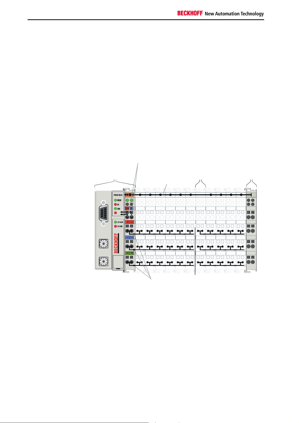
The principle of the bus
terminal
The K-bus is the path taken by data within the terminal row. The bus
terminal controller carries the K bus through all the terminals by means of
six contacts on the side walls of the terminals, and the end terminal
terminates the K bus. The user does not need to know anything about the
function of the K bus or the internal operation of terminals and bus terminal
controllers. There are numerous software tools available which provide for
convenient planning, configuration and operation.
Three power contacts pass the operating power to the following terminals.
You can use power input terminals to subdivide the terminal row as desired
into groups, each with a separate power supply. These power input
terminals are not taken into account for addressing the terminals, you can
insert them at any position along the terminal row.
You can install up to 64 terminals on a terminal row, including power input
terminals and the end terminal.
Bus terminal
controller
BC3100
Powersupply Potential
for the input
BC3100 terminal
terminal
K- bus
x1
x10
BC3100
PotentialPower
Additional characteristics of
the bus terminal controllers
Bus terminal controllers for
various field bus systems
6
The bus terminal controllers (BC) differ from the bus couplers (BK) by
virtue of the fact that a real time PLC task runs in addition to processing of
the K-bus. Contrary to the bus couplers, by default the signals of the
terminals are processed by the PLC task while inputs and outputs of the
PLC task are then transmitted through the field bus. It is possible, however,
to split up terminals so that some terminals are preprocessed by the PLC
task, while others are forwarded directly via the field bus to the higher-level
system.
Various bus terminal controllers can be used to link the electronic terminal
strip with an integrated PLC task swiftly and easily to diverse field bus
systems. Later conversion to a different field bus system is also possible.
The bus terminal controller assumes all checking and control tasks that are
needed for operation of the connected bus terminals. The bus terminals
are operated and configured exclusively via the bus terminal controller. The
field bus, the K-bus and the I/O level are electrically isolated.
BC3100
Page 7
Basic information
02
01
+
4
3
2
1
Power LEDs
Bus coupler / power contacts
The PLC task continues running as an autonomous system if the exchange
of data via the field bus should temporarily fail.
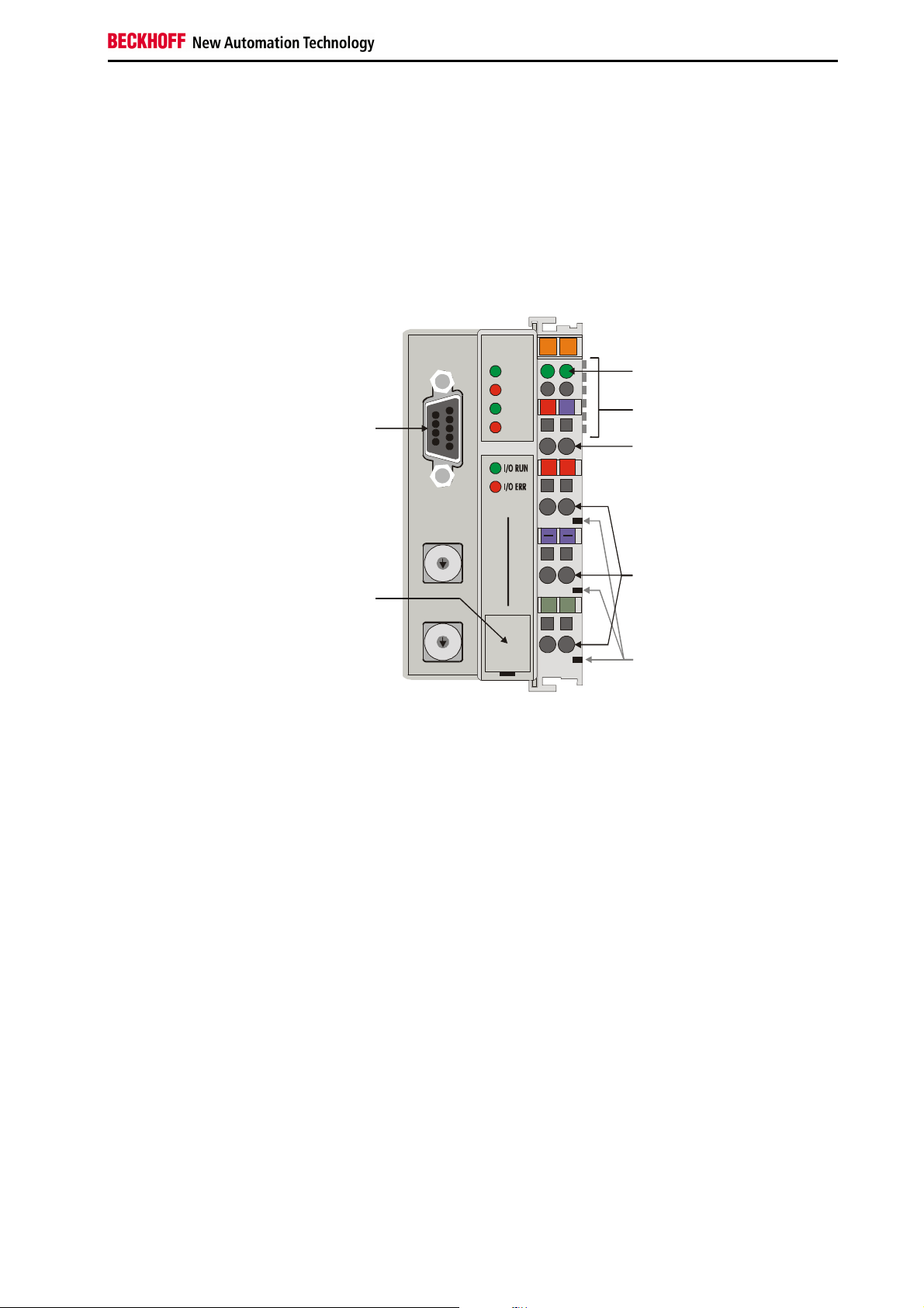
The interfaces
There are six ways of making a connection to a bus terminal controller.
These interfaces are designed as plug connections and spring terminals.
The Profibus controller
BC3100
PROFIBUS
RUN
BF
DIA
24V
00X0
0V
K-bus
Profibus
Power supply bus coupler
+
24 V DC / GND
x1
0
1
9
2
8
3
7
4
6
x10
0
9
8
7
6
5
BECKHOFF
BC3100
PE PE
5
Configuration
port
24 V DC on the topmost
terminals
Power supply
The bus terminal controllers need an operating power of 24 V DC which is
connected via the topmost spring terminals, labeled "24 V“ and "0 V“. This
power supply serves not only the electronic components of the bus
terminal controller but (via the K bus) also the bus terminals. The power
supply of the bus terminal controller circuitry and that of the K-bus
(Terminal bus) are electrically isolated from the voltage of the field level.
Lower 3 terminal pairs for
power input
maximum 24 V
maximum 10 A
Power supply to the power contacts
The six lower connections with spring terminals can be used to supply
power to the peripherals. The spring terminals are connected in pairs to the
power contacts. The power supply to the power contacts has no
connection to the power supply of the bus couplers. The power input is
designed to permit voltages up to 24 V. The pair-wise arrangement and the
electrical connection between the feed terminal contacts makes it possible
to loop through the wires connecting to different terminal points. The load
on the power contact may not continuously exceed 10 A. The current
capacity between two spring terminals is the same as the capacity of the
connecting wires.
Spring contacts at the side
Power contacts
On the right-hand side face of the BC3100 are three spring contacts which
are the power connections. The spring contacts are recessed in slots to
prevent them from being touched. When a bus terminal is connected, the
blade contacts on the left-hand side of the bus terminal are connected to
BC3100
the spring contacts. The slot and key guides at the top and bottom of the
Input
power contacts
power contacts
7
Page 8

Basic information
bus terminal controller and bus terminals ensure reliable location of the
power contacts.
9-pin Sub-D female
connector
Serial interface under the
front flap
6 contacts at the side
3 supply groups:
fieldbus
K-bus
peripheral level
Fieldbus connection
On the left-hand side there is a flat recessed area where you can plug in
the typical Profibus male connectors. You will find a detailed description of
the fieldbus interfaces in another part of this manual (In the chapter "The
transfer medium: plugs and cables“).
Configuration interface
On the bottom side of the front area, the bus terminal controllers are
equipped with an RS 232 interface. The miniature connector can be
connected to a PC with a connecting cable and the KS2000 configuration
software. The interface permits configuration of the analog channels.
Depending on the scope of performance of the field bus, this functionality
can also be realized with field bus-specific functions.
The miniature connector also serves to connect to the TwinCAT PLC
programming environment on a PC. It is used to load, start and stop the
program, breakpoints are set and the program is run in the STEP mode
etc.
Depending on the scope of performance of the field bus and the availability
of a corresponding TwinCAT field bus interface, this functionality can also
be realized via the field bus, with the result that several bus terminal
controllers that are physically connected to the same field bus can be
operated without replugging an RS 232 connection. This feature is
currently not yet supported by TwinCAT.
K-bus contacts
The connections between the BC3100 and the bus terminals are effected
by gold contacts at the right-hand side of the bus terminal controller. When
the bus terminals are plugged together, these gold contacts automatically
complete the connection to the bus terminals. The K-bus is responsible for
the power supply to the electronic components of the K-bus in the bus
terminals, and for the exchange of data between the BC3100 and the bus
terminals. Part of the data exchange takes place via a ring structure within
the K-bus. Disengaging the K bus, for example by pulling on one the bus
terminals, will break this circuit so that data can no longer be exchanged.
However, there are mechanisms in place which enable the bus terminal
controller to locate the interruption and report it.
Supply isolation
The BC3100 operate with three independent supplies. The input power
supplies the electrically isolated K-bus circuitry in the bus terminal
controller and the K-bus itself. The power supply is also used to generate
the operating power for the fieldbus.
Note: All the bus terminals are electrically isolated from the K bus, so that
the K-bus is completely electrically isolated.
8
BC3100
Page 9
Basic information
Periphery level
Bus terminals
Bus coupler
24 V DC
Bus terminal test Structure list
Setting up the power levels
in the bus terminal system
K-bus
Field bus
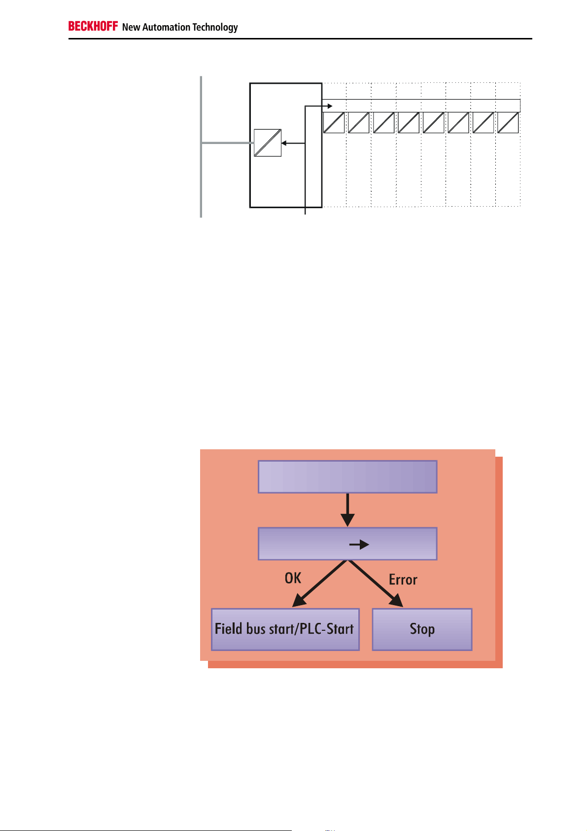
Start-up behavior of the bus
terminal controller
The operating modes of the bus coupler
After power on, in a "self-test" the bus terminal controller checks all
functions of its components and communication by the K-bus. The red I/O
LED flashes during this phase. After successful completion of the self-test,
the bus terminal controller begins to test the plugged in bus terminals (bus
terminal test) and reads the configuration. An internal structure list is
created on the basis of the bus terminals' configuration. The bus terminal
controller assumes the "STOP" operating state in the event of an error.
After error-free start up, the bus terminal controller assumes the "field bus
start/PLC start" state. If a PLC program is stored in the flash memory, it is
loaded and started regardless of whether the field bus is running. The
inputs of the PLC task have been set to zero during start up.
Power on selftest
BC3100
Depending on the field bus functionality, the bus terminal controller reports
a possible error via the field bus. The BC3100 generally has to be restarted
after the error has been remedied.
9
Page 10
Basic information
020201
01
+++
+
PEPEPE
PE
RUN
DIA
24V
4
3
2
1
0
0
47
12
X1
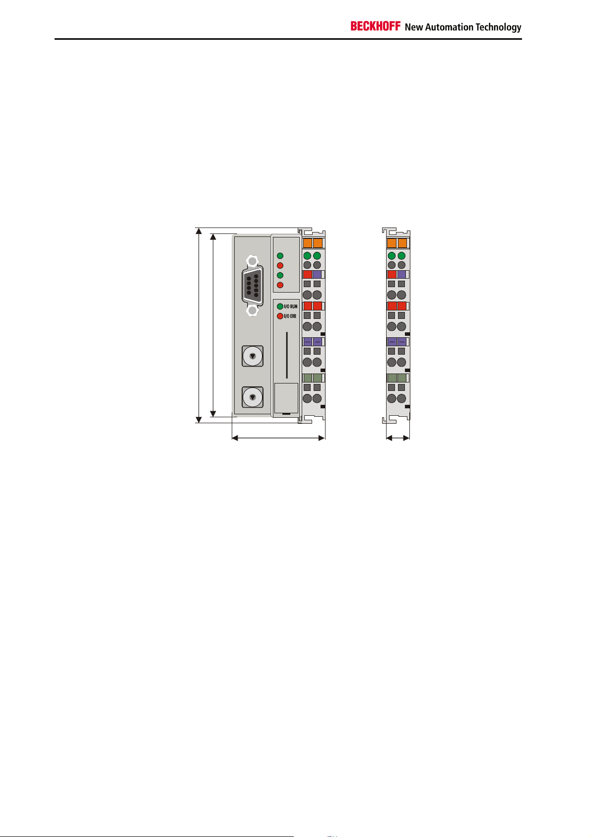
Mechanical construction
The Beckhoff bus terminal system is remarkable for its compact
construction and high degree of modularity. When you design the
installation you will need to plan for one bus terminal controller and some
number of bus terminals. The dimensions of the bus terminal controller do
not depend on the fieldbus system. If you use large plugs, for example like
some of the bus plugs used for the Profibus, they may protrude above the
overall height of the cabinet.
Dimensions of a bus
terminal controller
PROFIBUS
BF
24V
0V 0V
94
0
1
9
2
8
3
7
4
6
5
BECKHOFF
X10
0
1
9
8
7
6
5
The overall width of the construction is the width of the BC3100, including
the bus end terminal, plus the width of the installed bus terminals. The bus
terminals are 12 mm or 24 mm wide, depending on their function.
Depending on the gauge of cables used the overall height of 68 mm may
be overstepped by about 5 mm to 10 mm by the cables at the front.
Assembly and connections
It takes only a slight pressure to latch the bus terminal controller and the
various bus terminals onto a supporting 35mm C rail and a locking
mechanism then prevents the individual housings from being removed.
You can remove them without effort if you first release the latching
mechanism by pulling the orange tab. You should carry out work on the
bus terminals and the bus terminal controller only while they are switched
off: if you plug or unplug components while the power is on you may briefly
provoke some undefined state (and, for instance, reset the bus coupler).
You can attach up to 64 bus terminals in series on the right-hand side of
the BC3100. When you assemble the components, make sure that you
mount the housings so that each slot comes together with the
corresponding key. You cannot make any functional connections merely by
pushing the housings together along the supporting track. When they are
correctly mounted there should be no appreciable gap between the
adjacent housings.
The right-hand side of a BC3100 is mechanically similar to a bus terminal.
There are eight connections on the top which can be used to connect to
thick-wire or thin-wire lines. The connection terminals are spring loaded.
BC3100
10
BC3100
Page 11

Basic information
Insulation test
PE power contacts
You open a spring terminal by applying a slight pressure with a screwdriver
or other pointed tool in the opening above the terminal and you can then
insert the wire into the terminal without any obstruction. When you release
the pressure the terminal will automatically close and hold the wire
securely and permanently.
The connection between bus terminal controller and bus terminals is
automatically effected by latching the components together. The K bus is
responsible for passing data and power to the electronic components of the
bus terminals. In the case of digital bus terminals, the field logic receives
power via the power contacts. Latching the components together has the
effect that the series of power contacts constitutes a continuous power
track. Please refer to the circuit diagrams of the bus terminals: some bus
terminals do not loop these power contacts through, or not completely (e.g.
analog bus terminals or 4-channel digital bus terminals). Each power input
terminal interrupts the series of power contacts and constitutes the
beginning of a new track. The bus terminal controller can also be used to
supply power to the power contacts.
The power contact labeled "PE“ can be used as protective earth or ground.
This contact stands proud for safety reasons and can carry short-circuit
currents of up to 125A. Note that in the interests of electromagnetic
compatibility the PE contacts are capacitively connected to the supporting
track. This may lead to spurious results and even damage to the terminal
when you test the insulation (e.g. insulation test for breakdown using a
230V mains supply to the PE line). You should therefore disconnect the PE
line on the bus coupler while you carry out insulation tests. You can
disconnect other power supply points for the duration of the test by drawing
the power supply terminals out from the remaining row of terminals by at
least 10mm. If you do this, there will be no need to disconnect the PE
connections.
The protective earth power contact ("PE“) may not be used for any other
connections.
BC3100
11
Page 12

Basic information
Electrical data
The electrical data specific to the field bus is listed in this chapter. The
following table shows the data in an overview:
Technical data’s BC3100
Number of bus terminals
Digital peripheral signals
Analog peripheral signals
Maximum number of bytes
Programming possibility
Program size
Program memory
Data memory
Permament flags
Run time system
PLC cycle time
Programming languages
Field bus interface
Baud rates
Bus connection
Power supply
Input current
Power-on current
Recommended fuse
K-bus power supply up to
Power contact voltage
Power contact current load
Diaelectric strength
Operating temperature
Storage temperature
Relative humidity
Vibration/shock resistance
EMC/emssion
Installed position
Degree of protection
64
256 inputs/outputs
128 inputs/outputs
512 bytes I and 512 bytes O
via programming interface (TwinCAT BC) or Profibus-DP (TwinCAT)
approximately 3000 plc statements
32 kbytes
32 kbytes
512 bytes
1 PLC task
approximately 3 ms for 1000 commands (including K-bus I/O cycle)
IL, LAD, CSF, SFC, ST
Profibus-DP
automatic baud rate detection up to 12 MBaud
1 x D-sub connector, 9-pole, with screen
24 V DC, (20...29 V DC)
70 mA + (total K-bus current/4
500 mA max.
2.5 x continuous current
≤ 10 A,
1750 mA
24 V DC max.
10 A max.
500 Vrms (Power contact/supply voltage/field bus)
0°C ... +55°C
-25°C ... +85°C
95%, no condensation
in accordance withIEC 68-2-6 / IEC 68-2-27
in accordance with EN 50082 (ESD, Burst) / EN 50081
any
IP20
Current consumption on the
K-Bus
For operation of the K-bus electronics, the bus terminals require energy
from the K-bus that is supplied by the bus terminal controller. Refer to the
catalog or the corresponding data sheets of the bus terminals for details of
the K-bus current consumption. In doing so, pay attention to the maximum
output current of the bus terminal controller that is available for powering
the bus terminals. Using a special power supply terminal (KL9400), power
can be fed back into the K-bus at any chosen point. If you wish to use a
power supply terminal, please contact Beckhoff’s technical support.
12
BC3100
Page 13

Basic information
The peripheral data in the process image
After power on, the BC3100 determines the configuration of the plugged-in
input/output terminals. The affiliations between the physical slots of the
input/output channels and the addresses of the process image are defined
automatically or by programming by the bus terminal controller depending
on the settings via the configuration interface. If these affiliations are
programmed, digital and analog signals can be distributed channel by
channel in any order to the process image of the PLC task (global variables
%I* (inputs) and %Q* (outputs)) or of the field bus (process data that is
transferred through the field bus). The setting is defined manually with the
configuration interface or, depending on the field bus functionality of the
bus terminal controller, with the TwinCat System Manager at the variable
level.
By default, automatic allocation is set for the bus terminal controllers. This
is described below:
The BC3100 creates an internal allocation list in which the input/output
channels have a specific position in the process image. Here, a distinction
is made according to inputs and outputs and according to bit-oriented
(digital) and byte-oriented (analog or complex) signal processing.
Two groups with only inputs and only outputs each are formed. The byteoriented channels are located in ascending order at the lowest address in
one group. The bit-oriented channels are located after this block.
Digital signals
(bit-oriented)
Digital signals are bit-oriented. This means that one bit of the process
image is assigned to each digital channel. The bus terminal controller sets
up a block of memory containing the current input bits and arranges to
immediately write out the bits from a second block of memory which
belongs to the output channels.
The precise assignment of the input and output channels to the process
image of the control unit is explained in detail in the Appendix by means of
an example.
Analog signals
(byte-oriented)
The processing of analog signals is always byte-oriented and analog input
and output values are stored in memory in a two-byte representation. The
values are held as "SIGNED INTEGER“ or "twos-complement“. The digit
"0“ represents the input/output value "0V“, "0mA“ or "4mA“. When you use
the default settings, the maximum value of the input/output value is given
by "7FFF“ hex. Negative input/output values, such as -10V, are
represented as "8000“ hex and intermediate values are correspondingly
proportional to one another. The full range of 15-bit resolution is not
realized at every input/output level. If you have an actual resolution of 12
bits, the remaining three bits have no effect on output and are read as "0“
on input. Each channel also possesses a control and status byte in the
lowest value byte. If the control/status byte is mapped in the control unit
has to be configured in the master configuration software. An analog
channel is represented by 2 bytes user data in the process image.
Special signals and
interface
A bus terminal controller supports bus terminals with additional interfaces,
such as RS232, RS485, incremental encoder, etc.. These signals can be
regarded in the same way as the analog signals described above. A 16-bit
data width may not be sufficient for all such special signals; the bus coupler
can support any data width.
Word Alignment
The analog or special signals are mapped with word alignment when the
peripheral signals are allocated into the process image of the PLC task
BC3100
13
Page 14
Basic information
and, depending on the field bus, into the process image.
Process image allocation
By default, all terminals are allocated to the process image of the PLC task
(beginning with the address %Q*0 or %I*0) but, via the configuration
interface, the peripheral signals can also be allocated terminal by terminal
to the field bus process image, with the result that they would be
transmitted directly via the field bus without pre-processing by the PLC
task.
Default assignment of
inputs and outputs to the
process image
When the BC3100 is first switched on it determines the number of attached
bus terminals and sets up a list of assignments. This list distinguishes
between analog channels and digital channels and between input and
output; which are grouped separately. The assignments begin immediately
to the left of the BC3100. The software in the bus coupler creates the
assignment list by collecting the entries for the individual channels one at a
time, counting from left to right. These assignments distinguish four groups:
Function type of the channel Assignment level
1.
Analog outputs byte-wise assignment
2.
Digital outputs bit-wise assignment
3.
Analog inputs byte-wise assignment
4
Digital inputs bit-wise assignment
Analog inputs/outputs are representative of other complex multi-byte signal
bus terminals (RS232, SSI sensor interface, ...)
Output data in the BC3100
Overview of the subdivision of the process image in the BC3100
O0
...
byte-oriented data
...
Ox
Ox+1
bit-oriented data
Ox+y
Input data in the BC3100
I0
...
byte-oriented data
...
Ix
Ix+1
...
bit-oriented data
...
Ix+y
Assignment of the process
image of the PLC task to
the field bus process image
Depending on the setting, the affiliations between the inputs and the
outputs of the PLC task and the field bus process image are defined
automatically by the BC3100 via the configuration interface or by
programming. When assignments are programmed, inputs and outputs can
be distributed bit by bit in any order to the field bus process image. This is
set manually with the configuration interface or, depending on the field bus
functionality of the bus terminal controller, with the TwinCAT System
Manager at the variable level.
By default, automatic assignment is set for the bus terminal controllers. In
this case, one coherent area each of the inputs or outputs of the PLC task
can be mapped into the field bus process image. The initial offset and
14
BC3100
Page 15

Basic information
length of the area to be mapped can be set by way of the configuration
interface. As the terminal signals are placed into the process image of the
PLC task as from address zero, the first meaningful offset as from when
inputs and outputs of the PLC task are mapped into the field bus process
image is the first free address where there are no longer any terminal
signals.
Data consistency
Processing complex signals
Data which contains no contradictions is said to be consistent. The
following consistency is required here: 1. The high byte and low byte of an
analog value (word consistency), 2. The control/status byte and the
corresponding parameter word for accessing the register. The interaction
of the peripherals with the control unit means that data can initially be
guaranteed consistent only within an individual byte: the bits which make
up a byte are read in together, or written out together. Byte-wise
consistency is quite adequate for processing digital signals but is not
sufficient for transferring values longer than eight bits, such as analog
values. The various bus systems guarantee consistency to the required
length. It is important to use the appropriate procedure for importing this
consistent data from the master bus system to the control unit. You will find
a detailed description of the correct procedure in the User Guide of the
appropriate bus system, in particular in the description of the standard
master units that are installed. The chapters of this manual which deal with
the fieldbus refer to the most common of these standard units.
All byte-oriented signal channels such as RS232, RS485 and incremental
encoder, can use byte lengths greater than two. Apart from the actual
difference in length, the procedure is always comparable with that for
analog signals.
Commissioning and diagnostics
The diagnostic LEDs
After power on, the bus terminal controller immediately checks the
connected configuration. Error-free start up is signalled by virtue of the fact
that the red "I/O ERR" LED goes off. When it flashes, the "I/O ERR" LED
indicates an error in the area of the terminals. The error code can be
determined by the frequency and number of flashes. This enables swift
troubleshooting.
The bus terminal controller has two groups of LEDs to provide a status
display. The top group consisting of four LEDs indicates the status of the
respective field bus. The meanings of the "field bus" status LEDs are
explained in the corresponding chapters of this manual. They correspond
to the usual field bus displays.
There are two further green LEDs on the top right hand side of the bus
terminal controller to indicate the supply voltage. The left hand LED
indicates the 24 V power supply of the bus terminal controller. The right
hand LED signals the power supply of the Power contacts.
BC3100
15
Page 16

Basic information
Local errors
Two LEDs, the "I/O Leds" in the area under the above-mentioned field bus
status LEDs, serve to indicate the operating states of the bus terminals and
of the connection to these bus terminals. The green LED lights up
whenever the signals to the terminals are being exchanged via the K-bus.
After an error-free start up of the bus terminal controller, the K-bus
exchange always takes place, even if the PLC program or the field bus is
not running. The reaction (inputs or outputs change to zero or remain
unchanged) to errors (field bus not running correctly or PLC task has
assumed the STOP state) can be set via the configuration interface. To
indicate errors, the red LED flashes at two different frequencies. Errors are
encoded as follows in the flashing code:
Fast flashing
First slow sequence
Second slow sequence
Error code Error argument Description
1 pulse
2 pulses
3 pulses
4 pulses
5 pulses
6 pulses
8 pulses
9 pulses
0
1
2
0
n (n > 0)
0 Terminal bus command error
0
n
n Terminal bus error during register
0
p(p>0)
0
p(p>0)
0
The number of pulses (n) indicates the position of the last bus terminal
before the error. Passive bus terminals, for example an infeed terminal, are
not counted.
In the case of some errors, the bus terminal controller does not end the
flashing sequence when the error has been remedied. The bus terminal
controller's operating state is still "Stop". The bus terminal controller can
only be restarted by switching the supply voltage off and on or by means of
a software reset.
It is only permitted to unplug bus terminals from the network and to plug
them in again after switching off. The electronic circuitries of the bus
terminals and of the bus terminal controller are largely protected against
destruction, but malfunctions and damage cannot be ruled out if terminals
are plugged together under a live voltage.
The occurrence of an error during ongoing operation does not immediately
trigger output of the error code via the LEDs. The bus terminal controller
must be prompted to diagnose the bus terminals. The diagnostic request is
generated after power on.
Start of the error code
Error code
Error argument
EEPROM checksum error
Inline code buffer overflow
Unknown data type
Programmed configuration
Invalid table entry/
Bus terminal controller
Invalid table comparison (terminal n)
Terminal bus data error
Breakage after terminal n (0: BC3100)
communication with terminal n
Not enough DP-Cfg_Data received
Invalid DP-Cfg_Data byte
Not enough DP-User_Prm_Data received
Invalid DP-User_Prm_Data byte
Invalid checksum in the
PLC program
16
BC3100
Page 17

Basic information
Field bus error
PLC-RUN
PLC program in flash
memories
Cycle time of the PLC task
K-bus reaction time
The red BF LED on the bus terminal controller lights up whenever the
BC3100 is not participating in the Profibus-DP exchange of data.
The Green RUN LED on the bus terminal controller lights up whenever the
PLC task is in the RUN state.
When the PLC program is downloaded with the TwinCAT PLC
programming environment, the program is initially stored only in the RAM.
The program is transferred from the RAM to the flash memory by means of
the Online -> Create a boot project command. The red DIA LED on the bus
terminal controller goes on during this storage operation.
Run and reaction times
The PLC task is called up cyclically and time-controlled, whereby the cycle
time can be set via the configuration interface (default time: 5 ms). The
minimum cycle time is 1 ms. 20% of the timing resources should be
reserved for execution of the background processes. The PLC task's run
time is composed of the data exchange via the K-bus, the operating
system of the PLC task and the actual PLC program.
The PLC task's run time can be measured with the KS2000 configuration
software. The nominal cycle time and the time for background execution
can then be set on the basis of this measurement.
The reaction time on the K-bus is determined by shifting and saving of the
data. The following table contains measured values for typical setups. It is
possible to extrapolate to larger numbers.
Terminals inserted on the bus terminal
Digital
OUT
4 0 0 150
8 0 0 170
12 0 0 170
16 0 0 200
20 0 0 200
24 0 0 220
28 0 0 220
32 0 0 245
0 4 0 150
0 8 0 180
0 12 0 180
0 16 0 200
0 20 0 200
0 24 0 230
0 28 0 230
0 32 0 250
4 4 0 170
8 8 0 195
12 12 0 220
16 16 0 250
20 20 0 275
24 24 0 300
28 28 0 325
32 32 0 350
4 4 1 (KL3202) 630
4 4 2 (KL3202) 700
controller
Digital
IN
Analog
IN/OUT
Run time on the K-bus
T_cycle
(us)
BC3100
17
Page 18

Basic information
Memory requirement
Memory requirement for
various PLC commands
The PLC task currently has 32 kbytes each for program and data memory.
The memory requirement for a number of PLC commands is given below:
Command / Library Code Data Comment
32k available 32k RAM available
Overhead
BITFUN.LIB
CONVERT.LIB
COUNTER.LIB
MATH.LIB
STDFB.LIB
STRING.LIB
TIMER.LIB
TRIGONOM.LIB
LD/ST Byte variable
LD /ST Word variable
LD /ST Dword variable
ADD Byte variable
ADD Word variable
ADD Dword variable
SHL / ROL Byte variable
SHL / ROL Word variable
SHL / ROL Dword
variable
1k 6,5k
0 0 Created INLINE
0 0 Created INLINE
1.5k 0
-- -- Not yet available
1k 0
2.5k 0
1.5k 0
-- -- Not yet available
4
4
8
6
6
16
6
6
-- Not yet available
18
BC3100
Page 19

PROFIBUS-DP basics
System configurations and
device types
PROFIBUS-DP basics
Introducing the system
The PROFIBUS enjoys a very wide acceptance in automation technology
due to its openness and its wide manufacturer-independent distribution.
The PROFIBUS was developed in the course of a group project on the
fieldbus concept which aimed at agreeing on a standard. Numerous
different products are now available from independent manufacturers
which all conform to the standard DIN 19245 parts 1 and 2. Standardsconform PROFIBUS devices can be operated on any bus system.
PROFIBUS specifies the technical and functional characteristics of a serial
fieldbus system which can be used to network distributed digital and
analog field automation devices with low range (sensor/actuator level) to
midrange performance (cell level). PROFIBUS makes a distinction
between master and slave devices; master devices are those which govern
the data traffic on the bus.
A master may send messages without an external request, provided it has
the authority to access the bus. The PROFIBUS protocol also describes
masters as "active stations“.
Slave devices are peripheral devices. Typical slave devices are sensors,
actuators, transducers and Beckhoff bus couplers or bus terminal
controllers. They are not assigned any bus access privileges, i.e. they may
only acknowledge received messages or send messages to a master at its
request. Slaves are also referred to as passive stations.
PROFIBUS DP
PROFIBUS DP is designed for rapid data exchange at sensor/actor level,
where centralized control devices (such as stored program control units)
communicate with decentralized input and output devices by means of a
fast serial connection. The exchange of data with these decentralized
devices is carried out predominantly cyclically. The centralized control unit
(master) reads the input data from the slaves and writes the output data to
the slaves, whereby the cycle time of the bus needs to be shorter than the
program cycle time of the central control unit, which will be under 10 ms in
many applications.
Rapid data throughput alone is not sufficient for the successful
implementation of bus system. Ease of handling, good diagnostic facilities
and fault-proof data transfer technology must all be provided in order to
fulfill the users’ requirements. The characteristics have been optimally
combined in PROFIBUS DP.
At a data transfer rate of 12 Mbits/s, Profibus-DP needs less than 2 ms to
transfer 512 bits of input data and 512 bits of output data distributed to 32
stations. This meets the requirement for a short system reaction time.
You can use PROFIBUS DP to implement mono-master or multi-master
systems, which gives you a high degree of flexibility as regards the system
configuration. Up to 126 miscellaneous devices (master or slaves) can be
BC3100
19
Page 20

PROFIBUS-DP basics
attached to one bus. The bus couplers BK3xx0 permit you to select a
station address between 0 and 99. The quantities specified in the system
configuration include the number of stations, the assignments of station
addresses to I/O addresses, the consistency of the I/O data, the format to
be used for diagnostic messages and bus parameters that are to be used.
Each PROFIBUS DP system is made up of a number of different types of
device. We distinguish three types, depending on the tasks involved:
DP master class 1 (DPM1), such as an IM308-C or TwinCAT
This is a central control unit which exchanges information with the
decentralized stations (DP slaves) in a fixed message cycle. Typical
devices include stored program control units (PLC), numeric control units
(CNC) or robot control units (RC).
DP master class 2 (DPM2)
Devices of this type are programming, planning or diagnostic devices. They
are used to configure the DP system when the equipment is set up and
taken into service.
DP slave, e.g. the bus couplers or bus terminal controllers.
A DP slave is a peripheral device (sensor/actor), which reads in input
information and passes output information to the peripherals. Devices
which only input information, or only output information, are also possible.
Typical DP slaves are devices with binary I/O ports for 24V or 230V,
analog inputs, analog outputs, counters etc.. The volume of input and
output information depends on the individual device, up to a maximum of
244 bytes for input data and 244 bytes for output data. Due to cost factors,
and for technical and implementational reasons, many of the currently
available devices operate with a maximum data length of 32 bytes. The
Profibus coupler BK3000 can use the full length of 244 bytes, although the
master unit IM308-C restricts this to 52 bytes for input data. The IM308-B
enables you to use up to 122 bytes of input data.
In a mono-master system, only one master is active on the bus during the
operating phase of the bus system. The SPS control unit is die central
control element. The DP slaves are coupled to the SPS control unit
decentrally by means of the transfer medium. This system configuration
achieves the shortest bus cycle time.
In multi-master operation there are a number of masters on a single bus.
These either constitute independent subsystems, each consisting of one
DPM1 and the corresponding DP slaves or additional planning and
diagnostic devices. All the DP masters can read the input and output
mappings of the DP slaves. Although the output can be written by only one
DP master (namely the DPM1 which was appointed when the system was
specified). Multi-master systems achieve an average bus cycle time. If
timing is critical to your application you should connect up a diagnostic tool
to monitor increases in the bus cycle time.
Device master file (GSD)
The manufacturers of PROFIBUS DP provide users with documentation
covering the performance characteristics of the devices, in the form of a
device data sheet and a device master data file. The layout, content and
coding of this device master data (the GSD) are standardized. It facilitates
convenient project planning with any desired DP slaves using planning
20
BC3100
Page 21

PROFIBUS-DP basics
devices from a variety of manufacturers. The PNO archives this information
for all manufacturers and will supply information on request about
manufacturers’ device master files.
A PROFIBUS master configuration program reads the DMF data and
transfers the appropriate settings to the master. You will find a description
of this in the relevant software manual supplied by the manufacturer of
your master.
Type file (200)
The widespread and user-friendly master interfaces for a PLC include the
IM308-C from Siemens. A COMProfibus software under Windows is
available for configuration of the master. During configuration of this master
interface for the Profibus, the features of the slave devices are documented
by the manufacturers in the form of a type file and are made available to
users as a file. The contents and coding of this type file are Siemensspecific and are supported by Beckhoff, as well as by other manufacturers.
It enables convenient configuration of any chosen DP slaves with a PC
under the user interface of Windows 3.1 and subsequent Windows
versions. GSD files, type files and bitmaps are available for the Beckhoff
bus couplers or bus terminal controllers.
The GSD or type file can be downloaded from the mailbox 0 52 46 / 96 3 45 5, AREA 15, or via the Internet (www.beckhoff.com or ftp.beckhoff.com)
or can be ordered on a diskette.
Diagnostic functions
The extensive diagnostic functions of PROFIBUS DP make it possible to
localize errors rapidly. The diagnostic messages are transferred via the bus
and collated by the master. They are subdivided into three levels:
Diagnostic type
Station-
related
Module-
related
Channel-
related
Messages dealing with the general operating condition of
a subscriber, such as overheating or low voltage
These messages indicate a diagnostic message is
pending for a subscriber within a particular I/O sub-area
(e.g. 8-bit output module)
This locates the cause of the error in an individual input/
output bit (channel), such as: short circuit on output 2
The bus couplers and bus terminal controller support the diagnostic
functions of the PROFIBUS DP. The manner in which the control unit
evaluates the diagnostic data depends on what support is given by the
master. Please refer to the device manual of your master units to see how
to handle the diagnostics. (Note for ET200U experts: the diagnostics is
device-specific, as for the ET200U; a module in the bus terminal enables
you to evaluate the diagnostics for a specific station and track it right down
to an individual channel in the bus terminal.)
Sync and Freeze Mode
In addition to the subscriber-related user data traffic, which DPM1 deals
with automatically, the DP master can also send control commands to an
individual DP slave, to a group, or to all of the slaves simultaneously; these
control commands are transferred as multicast functions. You can use
such control commands to impose the operating modes Sync and Freeze
to synchronize the DP slaves. This facility provides for an event-driven
synchronization of the slaves. They enter Sync mode when they receive a
Sync control command from their appointed DP master. In this operating
mode, the outputs from all the DP slaves are frozen in their current state. If
user data is subsequently transferred, the output data is stored at the DP
slaves, although the output status values remain unchanged. When the
next Sync control command is received from the master, the stored output
BC3100
21
Page 22

PROFIBUS-DP basics
data is switched through to the outputs. The user can terminate Sync
operation by issuing an Unsync control command.
Similarly, a Freeze control command sends the addressed DP slaves into
Freeze mode. In this operating mode, the inputs of all the DP slaves are
frozen in their current state. The input data is not updated again until the
DP master sends the next Freeze control command to the relevant
devices. You terminate Freeze operation by issuing an Unfreeze control
command.
System behavior
To ensure that the devices are largely exchangeable, the system behavior
for the PROFIBUS DP has also been standardized. It depends principally
on the operating mode of the DPM1, which can be governed either locally
or from the planning device via the bus. The following principal modes are
distinguished:
Modes
Stop
Clear
Operate
No data communication is taking place between the DPM1 and
the DP slaves.
The DPM1 reads the input information of the DP slaves and keeps
the outputs of the DP slaves in a safe state.
The DPM1 is in the data transfer phase. In a cyclic
communication, the inputs of the DP slaves are read and the
output information is transferred to the DP slaves.
The DPM1 uses a multicast command to broadcast its local status
cyclically at regular intervals to all its subordinate DP slaves (the interval
can be configured). The system’s response to an error (such as the failure
of a DP slave) which occurs during the data transfer phase of the DPM1 is
determined by the operating parameter "Auto Clear“. If this parameter has
been set to "True“, then, as soon as any one DP slave ceases to be ready
to transfer user data, the DPM1 will switch the outputs of all its subordinate
DP slaves to a stable state and then enter Clear mode. If the parameter is
set to "False“, then the DPM1 will remain in Operate mode even in an error
situation and the user can govern the system response himself.
Data traffic between DPM1
and the DP slaves
The DPM1 automatically deals with data traffic between itself and its
subordinate DP slaves in a fixed and continually repeating order. During
the planning phase of the bus system, the user specifies which DP slaves
belong to which DPM1, which DP slaves should be included in the cyclic
transfer of user data, and which should be excluded from it.
The data traffic between the DPM1 and the DP slaves can be subdivided
into three phases: parametrization, configuration and data transfer. Before
it admits a DP slave to the data transfer phase, the DPM1 checks – in the
phases parametrization and configuration – whether the intended
configuration from the original plan agrees with the actual device
configuration. This check covers the device type, the format and length
information and the number of inputs and outputs, all of which must agree.
This gives the user reliable protection against parameter errors. In addition
to transferring user data, which the DPM1 carries out automatically, it is
also possible, at the user’s request, to transmit new parameters to the DP
slaves.
Protective mechanisms
In the field of decentralized peripherals, security considerations make it
imperative that systems should be equipped with highly effective protective
functions to prevent incorrect parametrization or a failure of the
communications equipment. On both the DP master and the DP slaves,
PROFIBUS DP uses monitoring mechanisms which are implemented as
22
BC3100
Page 23

PROFIBUS-DP basics
timeout monitors. The monitoring interval is specified when the DP system
is planned.
On the DP master
The DPM1 uses the Data_Control_Timer to monitor the transfer of user
data to and from the DP slaves. A separate monitoring timer is used for
each of the subordinate DP slaves. If a monitoring interval elapses without
any data being transferred, the monitor will report a timeout. The user will
be informed if this occurs. If automatic error response has been specified
(Auto_Clear = True), the DPM1 will leave Operate mode, switch the
outputs of its DP slaves to a secure state and go into Clear mode.
On the DP slave
Each DP slave maintains a response monitor to enable it to recognize
errors in the DP master or the transfer route. If a response monitoring
interval elapses without any data being exchanged with the superordinate
DP master, the DP slave will independently switch its outputs to the secure
state. In the case of a multi-master system additional security is necessary
to restrict access to the inputs and outputs of the DP slaves and to ensure
that direct accesses are made only by the authorized master. The DP
slaves therefore provide the other DP masters with a mapping of their
inputs and outputs which can be read by any DP master, even without
authority.
Identity number
Each DP slave and each DPM1 must have an individual identity number so
that a DP master can recognize the types of the attached devices without
entailing a significant protocol overhead. The master compares the identity
numbers of the attached DP devices with the identity numbers in the
planning data specified by the DPM2. No user data will be transferred
unless the correct device types have been attached to the bus with the
correct station addresses. This ensures that the system is protected from
planning errors.
Beckhoff PROFIBUS couplers, like all DP slaves and DPM1s, possess an
identity number allocated by the PNO. The PNO administers these identity
numbers together with the device master data and identity numbers are
also given in the type files.
BC3100
23
Page 24

PROFIBUS-DP basics
The transfer medium: plugs and cables
Physics of the transmission
Channel-related
disturbances
24
The physical data transfer is defined in the PROFIBUS standard. See
PROFIBUS layer 1 (physical layer).
The sphere of operation of a fieldbus system is substantially determined by
the selected transfer medium and the physical bus interface. Besides the
requirements of data transfer security, the necessary expenditure for
procuring and installing the bus cable is of crucial significance. The
PROFIBUS standard therefore provides for various forms of
communications technology while maintaining its standard bus protocol.
Cable transfer: this version, which confirms to the US standard EIA
RS-485, has been specified as the basic version for applications in the field
of production technology, building management technology and drive
technology. It uses a single twisted-pair copper cable. Shielding may be
unnecessary, depending on the planned application (take electromagnetic
compatibility aspects into consideration).
Two cable types with different maximum cable lengths are available. See
table entitled "RS485". The pin assignments on the connector and the
wiring are shown in the figure. Please pay attention to the special
requirements for the data cable at board rates in excess of 1.5 MBaud. The
right cable is a basic requirement for disturbance-free operation of the bus
system. When using the "normal" 1.5 Mbaud cable, astonishing
phenomena may occur as the result of reflections and excessive
attenuation. This may consist of the following: any one station is without a
connection and it resumes the connection when the neighbouring station is
extracted. Or, data transfer errors may occur when a certain bit pattern is
transferred. This means that the Profibus operates without disturbance but
without functioning of the system and randomly reports bus errors after
start up. The error behaviour described is eliminated by reducing the baud
rate ( < 93.75 kBaud).
If reducing the baud rate does not remedy the problem, this is frequently
due to a wiring error. Either the two data lines have been swapped on one
or several connectors or the terminators are not on or are activated in the
wrong place.
Fiber-optic conductor: the specification for a data transfer technology
based on fiber-optic conductors was elaborated in PNO for applications in
environments that are subject to extreme interference and to increase the
range at high data transfer rates. The specification is currently available as
a draft PNO guideline. The PROFIBUS COUPLER requires an external
module for conversion from RS485 to fiber-optic. The setup is clearly more
complex because of the need for an optical converter to convert from
RS485 to the "fiber-optic sub ring".
BC3100
Page 25

PROFIBUS-DP basics
1
5: GND
3: RxD/TxD- P
Pin assignments of the
D-Sub socket
RS-485
Data transfer technology
to the Profibus standard
Network
topology
Medium
Number of stations
Max. bus length
without repeaters
with repeaters
Transfer rates
Plug
RS485 fundamental characteristics:
Linear bus, active bus terminator at both ends,
branch lines are possible
Shielded twisted cable, shielding may be
dispensed with in suitable environments
(electromagnetic compatibility)
32 stations in each segment without repeaters,
extendible to 127 with repeaters
9.6, 19.2, 93.75 kBaud = 1200 m
187.5 kBaud = 1000 m
500 kBaud = 400 m
1500 kBaud = 200 m
3, 6 12 Mbaud = 100 m
Using repeaters (line amplifiers) increases the
max. bus length to the order of 10 km. The
number of possible repeaters is at least 3 and
may be up to 10, depending on the
manufacturer
9.6, 19.2, 93.75, 187.5, 500, 1500 Kbit/s, up to
12 Mbit/s in discrete steps
9-Pin D-Sub plug
Cables for
PROFIBUS DP and
PROFIBUS FMS
8: RxD/TxD- N
6
In systems which contain more than two stations, all the subscribers are
connected in parallel. The bus cable must always be terminated at the
ends of the lines, to prevent reflections and the transmission problems they
cause.
In order to loop the cable through without any gaps it is necessary to affix
two cables within one plug. Siemens’ SINEC L2 bus connections are very
suitable for this. These SINEC plugs are constructed to accommodate two
bus cables with the corresponding wire terminals and shielding. At the end
of the line you can use a small switch in the plug to activate the terminating
resistor. Please observe the manufacturer’s assembly instructions.
You should also note that the terminating resistor requires a 5 V power
supply for optimal operation. This means that if the plug is removed from
the bus coupler, or the power supply of the bus coupler fails, the level at
BC3100
25
Page 26

PROFIBUS-DP basics
the terminating resistor will vary, which may affect the data transfer.
Configuration of the masters
Example for the master
IM308-C
Interfacing for PLC Simatic
S5
The Profibus bus terminal controller operates with two different process
images: the PLC process image to which all bus terminals or only some of
the bus terminals configured on the one specific BC3100 are assigned, as
well as the Profibus DP process image to which a part of the bus terminals
can be assigned. For details of parameterization and configuration, please
refer to the chapter entitled Profibus bus terminal controller BC3100.
The Profibus master exchanges a coherent input and output data block
with each Profibus coupler/controller. The master assigns the bytes from
this data block from the addresses of the process image. The
COMProfibus software supports configuration when using the PLC master
of the IM308-C. Use the manufacturers' corresponding tools for other
masters (see also chapter entitled Master device file and type file).
Support files for master configuration:
Master / Software Remarks File
IM308-B
COMET200
IM308-C
COMProfibus
English
Language-
independent
General
General
General
In an example, we will show what settings have to be made in
COMProfibus to configure the Profibus master IM308-C.
Diverse bus terminals are connected to a BC3100:
In this example, the bus terminal controller's PLC program requires 5 bytes
of input signals (DP outputs of the master) and returns 6 bytes of output
signals (DP inputs of the master).
The corresponding entries for the identifiers can be selected conveniently
by way of the order number. The following window shows the selected
identifier:
BK3000TD.200
Bitmaps BUSKLEMN.BMP
BUSKLEMS.BMP
BK3000AD.200
BK3000AE.200
BK3000AX.200
(for BK30XX) BK30BECF.GSD
BK3010.GSD
(for BK31XX) BK31BECE.GSD
BK3110.GSD
(for BC3100) BC3100.GSD
26
BC3100
Page 27

PROFIBUS-DP basics
When a box in the "Order no." column is double clicked, a menu appears
for selection of the required identifier for the correspondingly plugged in
terminals or data lengths of the PLC process image.
Various possibilities of assigning process data are available in the case of
the BC3100. The various assignment possibilities are explained in detail in
the next chapter (Profibus bus terminal controller BC3100). In the
appendix, you will also find an example in relation to the possible settings.
BC3100
27
Page 28

PROFIBUS-DP basics
Ensuring data consistency
Consistency of a station's data is ensured by the Profibus data transfer
protocol. Consistency throughout the entire process image must be
achieved by activating the "SYNC" and "FREEZE" operating modes in the
masters.
FREEZE and SYNC capability is preselected for the slave parameters (see
figure) and cannot be deactivated. The control software checks FREEZE
and SYNC.
Activation of response monitoring ensures that an error message is created
in the event of failure of the corresponding station belonging to the master
and that the control software is enable to initiate exception handling.
Response monitoring can be selected individually for each station.
Response monitoring on is the default. The COMProfibus software issues
a warning whenever monitoring is to be deactivated.
Inconsistencies may occur as the result of asynchronous access by the
controller CPU (mostly PLC) to the data area of the Profibus master. Data
consistency is ensured automatically with the configuration of a "multi-byte
signal" and module consistency in the COMProfibus configuration software
for IM308-C. With regard to further master interfaces, please consult the
corresponding manufacturers' manuals for an explanation.
The IM 308-C as Profibus DP master is a common PLC interface.
A Windows program, COMProfibus, and extensive descriptions are
available for the Profibus DP master interface IM308-C. In connection with
the Siemens S5, it is recommended to use the IM308-C because of its
better handling and the possibility of freely assigning peripheral addresses
byte by byte. Versions 2.1 or higher can be considered to be particularly
convenient. An extended type file can be read in with these versions. The
entries in the type file automatically assume the settings for guaranteeing
data consistency. (The figures on the previous pages originate from the
COMProfibus software.)
28
BC3100
Page 29

PROFIBUS bus terminal controller BC3100
PROFIBUS bus terminal controller BC3100
Parameterization
Besides the parameterization in the DP standard, manufacturer-specific
operating parameters (User_Prm_Data) can also be transferred with the
Set_Prm service. These are distinguished by the fact that they are
transferred once from the master to the slave during establishment of the
connection. User_Prm_Data overwrites the settings that have been made
by way of the configuration interface. If these settings are not to be
overwritten, User_Prm_Data must not be sent. The User-Prm_Data of the
bus terminal controller BC3100 is based on the following structure:
Byte No. Description
Byte 0
Byte 1
Byte 2
Byte 3
Byte 4
Byte 5
Byte 6
Byte 7
Byte 8
Byte 9
Byte 10
Byte 11
Bit 0: Start-Bit monitoring on (0) / off (1)
Bit 1: Stop-Bit monitoring on (0) / off (1)
Bit 2: Watchdog time base 10ms (0) / 1ms (1)
Bit 3-5: 0 (reserved for expansions)
Bit 6: Fail_Safe off (0) / on (1)
Bit 7: DPV1-MSAC_C1 connection disabled (0) / enabled (1)
0 (reserved for expansions)
0 (reserved for expansions)
0 (reserved for expansions)
0 (reserved for expansions)
Bit 1: diagnostics via 2-byte diagnostics interface (1)
Diagnostics via DP diagnostics (Slave_Diag) (0)
Bit 0, 2-7: 0 (reserved for expansions)
0 ( reserved for expansions)
Bit 0: auto reset on the terminal bus in the event of an error on
(1)/off(0)
Bit 1: automatic terminal diagnostics on(1)/off(0)
Bit 4: diagnostics of digital terminals is mapped to the process
image (0)/ is not mapped to the process image (1)
Bit 2,3, 5-7: 0 (reserved for expansions)
0 (reserved for expansions)
Bit 0: 1
Bit 1: 1
Bit 2: 0
Bit 3: data format for auto configuration: INTEL (0)/MOTOROLA(1)
Bit 4: 0
Bit 5: 1
Bit 6: 1
Bit 7: 0
Bit 0,1: reaction to field bus error/termination of DP data
exchange/Clear_Data
1: affiliated terminal bus outputs change to 0
2: affiliated terminal bus outputs remain unchanged
Bit 2,3: Reaction to terminal bus error
1: affiliated DP inputs change to 0
2: affiliated DP inputs remain unchanged
Bit 4-7: 0 (reserved for expansions)
Max. DP diagnostic data length (value range 16, 24, 32, 40, 48, 56,
64)
BC3100
29
Page 30

PROFIBUS bus terminal controller BC3100
Byte No. Description
Byte 12
Byte 13
Reserved for expansions
Bit 0: flags are stored in the NOVRAM (1)/are not stored (0)
Bit 1: PLC run time measurement on (1)/off (0)
Bit 2,3: terminal bus/PLC cycle sequence
0: terminal bus inputs before PLC cycle, terminal bus outputs
after PLC cycle
1: terminal bus inputs and outputs before PLC cycle
2: terminal bus inputs and outputs after PLC cycle
Bit 4: Nominal cycle time and background execution time are
set via TWinCAT BC / TWinCAT PLC (1) / are set via
UserPrmData (0) (Byte 43: Nominal cycle time, Byte 44:
Background execution time)
Bit 5: BC state is copied into flag (1) (PROFIBUS state into flag
byte 508,509, terminal bus state into flag byte 510,511) / is not
copied into flag
Byte 14
Bit 0: 1
Bit 3: in the event of a PLC STOP, the affiliated terminal bus
outputs remain unchanged (1)/the affiliated terminal bus
outputs are set to 0 (0)
Bit 4: in the event of a terminal bus error, the affiliated PLC
inputs remain unchanged (1) / the affiliated PLC intputs are set
to 0 (0)
Bit 5: in the event of a field bus error, the affiliated PLC inputs
remain unchanged (1)/ the affiliated PLC inputs are set to 0 (0)
Bit 6: in the event of a PLC STOP, the affiliated DP outputs
remain unchanged (1)/the affiliated DP outputs are set to 0 (0)
Byte 15
Bit 0,1:
0: 1. Terminal is assigned to the DP process image
2: 1. Terminal is assigned to the PLC process image and is
mapped compactly (only with useful data)
3: 1. Terminal is assigned to the PLC process image and
mapped completely
Bit 2,3:
0: 2. Terminal is assigned to the DP process image
2: 2. Terminal is assigned to the PLC process image and
mapped compactly (only with useful data)
3: 2. Terminal is assigned to the PLC process image and
mapped completely
Bit 4,5:
0: 3. Terminal is assigned to the DP process image
2: 3. Terminal is assigned to the PLC process image and
mapped compactly (only with useful data)
3: 3. Terminal is assigned to the PLC process image and
mapped completely
Bit 6,7:
0: 4. Terminal is assigned to the DP process image
2: 4. Terminal is assigned to the PLC process image and
mapped compactly (only with useful data)
3: 4 Terminal is assigned to the PLC process image and
mapped completely
...
...
30
BC3100
Page 31

PROFIBUS bus terminal controller BC3100
Byte No. Description
Byte 30
Bytes 31-36
Byte 37
Byte 38
Byte 39
Byte 40
Byte 41
Byte 42
Byte 43
Byte 44
Bytes 45,46
Bit 0,1:
0: 61. Terminal is assigned to the DP process image
2: 61. Terminal is assigned to the PLC process image and
mapped compactly (only with useful data)
3: 61. Terminal is assigned to the PLC process image and
mapped completely
Bit 2,3:
0: 62. Terminal is assigned to the DP process image
2: 62. Terminal is assigned to the PLC process image and
mapped compactly (only with useful data)
3: 62. Terminal is assigned to the PLC process image and
mapped completely
Bit 4,5:
0: 63. Terminal is assigned to the DP process image
2: 63. Terminal is assigned to the PLC process image and
mapped compactly (only with useful data)
3: 63. Terminal is assigned to the PLC process image and
mapped completely
Bit 6,7:
0: 64. Terminal is assigned to the DP process image
2: 64. Terminal is assigned to the PLC process image and
mapped compactly (only with useful data)
3: 64. Terminal is assigned to the PLC process image and
mapped completely
Reserved for expansions
Initial address in the PLC input process image as from which
plc inputs are to be transferred as DP outputs (high byte)
Initial address in the PLC process image as from which PLC
inputs are to be transferred as DP outputs (low bytes)
Length of the PLC inputs that are to be transferred as DP
outputs
Initial address in the PLC output process image as from which
PLC outputs are to be transferred as DP Inputs (high bytes)
Initial address in the PLC output process image as from which
PLC outputs are to be transferred as DP inputs (low byte)
Length of the PLC outputs that are to be transferred as DP
inputs
Nominal PLC cycle time (in ms, value range: 1 - 255)
Background execution time (in ms, value range: 1 -255)
Length of the remanant flags (as from MB0, which are stored in
the NOVRAM, value range: 1 - 512)
If no bus terminal controllers assume the last programmed value. Remark:
the default setting of the User_Prm_Data can be taken from the GSD file.
BC3100
31
Page 32

PROFIBUS bus terminal controller BC3100
Configuration
2-byte diagnostic interface
Assignment of terminals
Digital terminals
Analog terminals
The configuration data to be transferred with the Chk_Cfg service defines
which process data is exchanged with the Data_Exchange service.
Identifier Description
0xB1
2-byte PLC interface
When the 2-byte diagnostic interface is activated, the next identifier in the
configuration data must be assigned as follows, as otherwise this identifier
is dropped:
Identifier Description
0xB1
2-byte diagnostic interface
Auto-configuration
When using auto configuration, only those terminals may be considered
that have been assigned to the DP process image.
The data of all digital input or output terminals is combined in one byte
array each in the sequence of the slots. The following identifiers can be
used for digital data:
Identifier Description
0x1n
0x2n
0x3n
These identifiers can be assigned as required so that the total of the input
or output bytes each corresponds to the existing data length of digital
inputs and outputs (rounded up to 1 byte).
As the digital data is transferred after all analog data, the digital identifiers
must be defined after all analog identifiers.
For each channel, the analog terminals have 8 bits of control or status data
and user data. These terminals belong to the intelligent terminals and
support register communication (8 bits of control or status data, 16 bits of
I/O data per channel). Specific coding in the control or status data defines
whether the first 16 bits of the user data are to be interpreted as register
communication I/O data.
One code must be defined for each analog terminal or each analog
channel. Their sequence depends on the slots.
There are up to 5 different codes per channel for mapping them in the DP
(n+1)-byte digital inputs
(n+1)-byte digital outputs
(n+1)-byte digital inputs and outputs
32
BC3100
Page 33

PROFIBUS bus terminal controller BC3100
process data:
Identifier Description
A:
Only the value is sent (no register communication possible)
B:
The complete channel is sent (register communication possible)
C:
The value plus control plus status is sent (no register
communication possible)
D:
The value plus status is sent (no register communication
possible)
E:
The value plus control is sent (no register communication
possible)
There are also 2 different identifiers per terminal for mapping them into the
process data.
Identifier Description
F:
Only the values are sent (up to 16 words) (no register
communication possible)
G:
All complete channels are sent (up to 16 words) (register
communication possible)
Therefore, for each analog channel, the master can decide how much data
the respective channel is to occupy in the process image.
As there are also DP masters that write back configuration read out in the
slave (e.g. CP5431 from Siemens), bit 2 from register 3 in Table 0 of the
bus terminal controller can be set to define whether the Cfg_Data of the
Get_Cfg service is to be mapped according to A (bit 2 = 0) or B (bit 2 = 1)
(see parametrisation). You have access to this table by way of the KS2000
configuration software.
BC3100
33
Page 34

PROFIBUS bus terminal controller BC3100
The DP configuration data for the various terminals is as follows:
Terminal
KL3002, KL3012,
KL3022, KL3032,
KL3042, KL3052,
KL3062, KL3202,
KL3302
KL3004, KL3014,
KL3024, KL3034,
KL3064
KL4002,
KL4012, KL4022,
KL4032
KL4004, KL4014,
KL4024, KL4034
KL1501
KL2502
KL5001
KL5101
KL6001, KL6011,
KL6021
DP Configuration data
Channel 1 Channel 2
A: 0x50 0x50
B: 0xB2 0xB2
C: 0xC0 0x00 0x82 0xC0 0x00 0x82
D: 0x40 0x82 0x40 0x82
E: 0xC0 0x00 0x81 0xC0 0x00 0x81
Total
F: 0x51
G: 0xF2
Channel 1 Channel 2 Channel 3 Channel 4
A: 0x50 0x50 0x50 0x50
B: 0xB2 0xB2 0xB2 0xB2
C: 0xC0 0x00 0x82 0xC0 0x00 0x82 0xC0 0x00 0x82 0xC0 0x00 0x82
D: 0x40 0x82 0x40 0x82 0x40 0x82 0x40 0x82
E: 0xC0 0x00 0x81 0xC0 0x00 0x81 0xC0 0x00 0x81 0xC0 0x00 0x81
Total
F: 0x53
G: 0xF5
Channel 1 Channel 2
A: 0x60 0x60
B: 0xB2 0xB2
C: 0xC0 0x82 0x00 0xC0 0x82 0x00
D: 0xC0 0x81 0x00 0xC0 0x81 0x00
E: 0x80 0x82 0x80 0x82
Total
F: 0x61
G: 0xF2
Channel 1 Channel 2 Channel 3 Channel 4
A: 0x60 0x60 0x60 0x60
B: 0xB2 0xB2 0xB2 0xB2
C: 0xC0 0x82 0x00 0xC0 0x82 0x00 0xC0 0x82 0x00 0xC0 0x82 0x00
D: 0xC0 0x81 0x00 0xC0 0x81 0x00 0xC0 0x81 0x00 0xC0 0x81 0x00
E: 0x80 0x82 0x80 0x82 0x80 0x82 0x80 0x82
Total
F: 0x63
G: 0xF5
B: 0xB4
G: 0xF2
B: 0xB2
G: 0xF2
A: 0xD1
B: 0xB4
C: 0xC0 0x00 0x84
D: 0x40 0x84
E: 0xC0 0x00 0x83
B: 0xB5
G: 0xF2
B: 0xB5
G: 0xF2
Auto mapping of the PLC
inputs and outputs
Once all terminals belonging to the DP process image have been defined,
the PLC input and output area mapped into the DP process image now
also has to be taken into account in DP configuration data.
In doing so, use must be made of the following identifiers, any number of
34
BC3100
Page 35

PROFIBUS bus terminal controller BC3100
which can be used. The only restriction is that the length of the respective
area must come out at the end (The identifiers need not be entered
manually. They can be inserted via a selection list):
Identifier Description
0x90
0x91
0x9F
0x40,
0x90
0x40,
0x91
0x40,
0xBF
0xA0
0xA1
0xAF
0x80,
0x90
0x80,
0x91
0x80,
0xBF
1-byte PLC outputs (DP inputs)
2-byte PLC outputs (DP inputs)
...
...
16-byte PLC outputs (DP inputs)
17-byte PLC outputs (DP inputs)
18-byte PLC outputs (DP inputs)
...
...
64-byte PLC outputs (DP inputs)
1-byte PLC inputs (DP outputs)
2-byte PLC inputs (DP outputs)
...
...
16-byte PLC inputs (DP outputs)
17-byte PLC inputs (DP outputs)
18-byte PLC inputs (DP outputs)
...
...
64-byte PLC inputs (DP outputs)
Diagnostics
Diagnostic messages of the
terminals
Besides the fixed diagnostics data, external diagnostics data can also be
communicated with the Slave_Diag service. In the case of the external
diagnostic data, the device-specific diagnostics format is used, in which
each diagnostic message occupies 8 bytes. As the device-specific
diagnostic data must not be more than 63 bytes long, up to 7 different
diagnostics messages can be transferred. If more than 7 different
diagnostics messages have occurred, the Ext_Diag_Overflow diagnostics
flag is set in the fixed diagnostics data. The Ext_Diag_Data is structured as
follows:
Byte No Description
Byte 0:
Byte 1:
Byte 2 - x:
There is one diagnostics message for each terminal, which is based on the
following structure:
Device-specific diagnostics header
0 (reserved for expansions)
8 bytes per diagnostics message (x: 9,17,25,33,41,49,57)
BC3100
35
Page 36

PROFIBUS bus terminal controller BC3100
Byte No Description
Byte 0
Byte 1
Byte 2
Byte 3
Byte 4
Byte 5
Byte 6
Byte 7
Terminal No (1-64)
Channel No (1-4)
PLC process image, low byte address
PLC process image, high byte address
PLC process image bit address
Analog terminals: status byte of the terminal
Digital terminals: bit 1: short circuit channel 0
short circuit channel 1
(reserved for expansions)
(reserved for expansions)
The PLC process image addresses are entered only if the corresponding
tables have been transferred (see Table 80 in the bus coupler).
Diagnostics messages of
the bus coupler
Besides the diagnostics messages of the terminals, there are also 2
diagnostics messages of the bus coupler.
Byte No Description
Byte 0
Byte 1
Byte 2
Byte 3
Byte 4
Byte 5
Byte 6
Byte 7
0
0
Initialisation error
Terminal bus error
Invalid test on bus reset or invalid terminal number in the event of a
terminal bus error
Invalid terminal number on bus reset
First terminal number not supported
0
Byte No Description
Byte 0
Byte 1
Byte 2
Byte 3
Byte 4
Byte 5
Byte 6
Byte 7
0
255
UserPrmData error
0: No error
1: Reserved
2: Input or output data too long
3: Invalid byte or word of the UserPrmData
First invalid byte or word of the UserPrmData
CfgData error
0: No error,
1: Not enough CfgData,
2: Invalid CfgData byte,
3: Error generating the DP process image
4: Error generating the PLC process image (BC3100 only)
Byte 4 = 2:
First invalid byte of the CfgData (0 - 63)
Byte 4 = 3:
0: Maximum input or output length exceeded
2: Compile buffer in the case of the DP process image is too small
Byte 4 = 4:
0: Maximum input or output length exceeded
2: Compile buffer in the case of the PLC process image is too small
(BC 3100 only)
0
0
Initialisation
error
Bit 0
Description
Error reading out the EEPROMs
36
BC3100
Page 37

PROFIBUS bus terminal controller BC3100
Bit 1
Bit 2
Bit 3
Bit 4
Bit 5
Bit 6
Bit 7
Compile buffer is too small
Error checking the programmed configuration
Error reading out the terminal types on the terminal bus
Terminal is not supported
Too many configuration data items
Too many output data items (excessive total of the output
data of all terminals)
Too many input data items (excessive total of the input data
of all terminals)
If an initialisation error occurs, the fixed dignostics data Stat_Diag flag is
set, the result being that no process data cycle is realised on the terminal
bus.
Terminal-
bus error
Bit 0
Bit 1
Bit 2
Bit 3
Bit 4
Bit 5
Bit 6-7
Description
Too many errors sending a command on the terminal bus (slave
has detected an error while comparing the command and the
inverted command)
Too many timeouts during command execution (slave has not
acknowledged command execution)
Too many errors of receiving the input data (Master has detected
an error when comparing input data and inverted input data)
Too many errors when sending the output data (slave has
detected an error when comparing output data and inverted
output data)
Error on bus reset
Terminal bus error
--
Data exchange
The process data is placed in the input and output data according to the
transferred configuration. In doing so, the digital data follows all analog
data.
The BC3100 currently supports up to 128 bytes of input or output data.
As it is possible to set, via the configuration interface or the
User_Prm_Data whether the user data can be placed in the process image
in the INTEL or the MOTOROLA format, these values can be mapped in
such a way that word or double word access is possible in the master
without byte swapping.
Siemens DP master
(IM 308B, IM 308C, CP5431)
KL3002, KL3012,
KL3022, KL3032,
KL3042, KL3052,
KL3062, KL3202,
A: MOTOROLA
B: MOTOROLA
C: MOTOROLA
D: MOTOROLA
BC3100
37
Page 38

PROFIBUS bus terminal controller BC3100
KL3302
KL3004, KL3014,
KL3024, KL3034,
KL3064
KL4002,
KL4012, KL4022,
KL4032
KL4004, KL4014,
KL4024, KL4034
KL 1501
KL 2502
E: MOTOROLA
F: MOTOROLA
G: MOTOROLA
A: MOTOROLA
B: MOTOROLA
C: MOTOROLA
D: MOTOROLA
E: MOTOROLA
F: MOTOROLA
G: MOTOROLA
B: MOTOROLA
G: MOTOROLA
B: MOTOROLA
G: MOTOROLA
Siemens DP master
(IM 308B, IM 308C, CP5431)
KL5001
KL 5101
KL6001, KL6011,
KL6021
A: MOTOROLA
B: MOTOROLA
C: MOTOROLA
D: MOTOROLA
E: MOTOROLA
B: MOTOROLA
G: MOTOROLA
B: No influence
G: No influence
Bosch DP master
KL3002, KL3012,
KL3022, KL3032,
KL3042, KL3052,
KL3062, KL3202,
KL3302
KL3064
KL4002,
KL4012, KL4022,
KL4032
KL 1501
KL 2502
KL5001
KL 5101
KL6001, KL6011,
KL6021
A: MOTOROLA
B: INTEL
C: INTEL
D: INTEL
E: INTEL
F: MOTOROLA
G: Mapping difficult
B: MOTOROLA
G: Mapping difficult
B: MOTOROLA
G: Mapping difficult
A: Mapping difficult
B: INTEL
C: INTEL
D: INTEL
E: INTEL
B: INTEL
G: Mapping difficult
B: No influence
G: Mapping difficult
The other respective setting is naturally also possible, but leads to a
situation in which bytes have to be swapped in the DP Master (or in the
PLC) before word or double word access to them is possible. The "difficult
to map" comment means that the individual bytes have to be remapped in
the DP master, when using both the INTEL and the MOTOROLA formats,
to enable individual access to them.
38
BC3100
Page 39

PROFIBUS bus terminal controller BC3100
Global_Control
Set_Slave_Address
Terminal register
(Slot_Number: 1 – 64)
Other DP services
Sync and Freeze mode, both of which are supported by the bus terminal
controllers, are controlled with the Global_Control service. Thus, the
Clear_Data command is also set, which has the reaction defined in bits 8
and 9 from Register 3 in Table 0 of the bus terminal controller (see
Parametrisation).
For the time being, modification of the station address via the bus is not
supported.
Acyclic DPV1 services
The register of terminals and the input, output and flag process image can
be accessed acyclically with the DPV1 services. Additionally, the available
terminals can be read out and the cycle time can be measured.
The BC3100 supports the MSAC_C1 connection for the DP master class 1
as well as a MSAC_C2 connection for a second master with a maximum
PDU length of 52 bytes (48 bytes of data). The significance of
Slot_Number and Index for read and write services will be described in the
following.
As registers are only available to complex terminals, these are the only
ones that must be considered when assigning the Slot_Number. The first
complex (analogue) terminal is addressed with Slot_Number = 1, the next
with Slot_Number = 2, etc. The Index designates the register number. The
number of registers, which are to be read or written, can be determined
from the length (in bytes, must be even as the terminal register is built up in
words).
BC3100
39
Page 40

PROFIBUS bus terminal controller BC3100
Bus coupler
(Slot_Number: 0)
Bus controller data are addressed via Slot_Number 0. The following
Indexes are thus defined:
Index Read
0x00
0x01-0x03
0x21
0x80 – 0x8A
0x90 – 0x9A
0xA0 – 0xAA
Reserved for AMS
Table 9: Terminal designations (Length = 2 – 48 bytes):
Index 1: Register 0- 23
Index 2: Register 24 – 47
Index 3: Register 48 – 64
Cycle times of the PLC (Length = 8 bytes):
Word 0: minimum cycle time (in 1/125 ms)
Word 1: maximum cycle time (in 1/125 ms)
Word 2: actual cycle time (in 1/125 ms)
Word 3: average cycle time (in 1/125 ms)
PLC outputs (Length = 1 – 48 bytes):
Index 0x80: Offset 0 – 47
Index 0x81: Offset 48 – 95
Index 0x82: Offset 96 – 143
Index 0x83: Offset 144 – 191
Index 0x84: Offset 192 – 239
Index 0x85: Offset 240 – 287
Index 0x86: Offset 288 – 335
Index 0x87: Offset 336 – 383
Index 0x88: Offset 384 – 431
Index 0x89: Offset 432 – 479
Index 0x8A: Offset 480 – 511
PLC inputs (Length = 1 – 48 bytes):
Index 0x80: Offset 0 – 47
Index 0x81: Offset 48 – 95
Index 0x82: Offset 96 – 143
Index 0x83: Offset 144 – 191
Index 0x84: Offset 192 – 239
Index 0x85: Offset 240 – 287
Index 0x86: Offset 288 – 335
Index 0x87: Offset 336 – 383
Index 0x88: Offset 384 – 431
Index 0x89: Offset 432 – 479
Index 0x8A: Offset 480 – 511
PLC flag (Length = 1 – 48 bytes):
Index 0x80: Offset 0 – 47
Index 0x81: Offset 48 – 95
Index 0x82: Offset 96 – 143
Index 0x83: Offset 144 – 191
Index 0x84: Offset 192 – 239
Index 0x85: Offset 240 – 287
Index 0x86: Offset 288 – 335
Index 0x87: Offset 336 – 383
Index 0x88: Offset 384 – 431
Index 0x89: Offset 432 – 479
Index 0x8A: Offset 480 – 511
40
BC3100
Page 41

PROFIBUS bus terminal controller BC3100
Index Write
0x00
0x10
0x20
0x21
0xE0
0xE1
0xE2
0xE3
0xE4
0xE5
Reserved for AMS
Functions (Length = 1 – 3 bytes):
Byte 0: 0 – Set write protection (Byte 1, 2 != 0xAFFE),
reset (Byte 1 = 0xFE, Byte 2 = 0xAF)
Byte 0: 1 – Set manufacturer configuration
Byte 0: 2 – Terminal bus reset
Start cycle time measurement (Word 0 != 0) / stop (Word 0
= 0) (Length = 2 bytes)
Initialise cycle times of the PLC (Length = 8 bytes):
Word 0: minimum cycle time (in 1/125 ms)
Word 1: maximum cycle time (in 1/125 ms)
Word 2: actual cycle time (in 1/125 ms)
Word 3: average cycle time (in 1/125 ms)
Write PLC output bytes (Length = 3 – 48 bytes)
Byte 0/1: Byte-Offset
Byte 2-n: Data
Write PLC input bytes (Length = 3 – 48 bytes)
Byte 0/1: Byte-Offset
Byte 2-n: Data
Write PLC flag bytes (Length = 3 – 48 bytes)
Byte 0/1: Byte-Offset
Byte 2-n: Data
Write PLC output bits (Length = 3 bytes)
Byte 0/1: Bit-Offset
Byte 2: Bit is set (1) / reset (0)
Write PLC input bits (Length = 3 bytes)
Byte 0/1: Bit-Offset
Byte 2: Bit is set (1) / reset (0)
Write PLC flag bits (Length = 3 bytes)
Byte 0/1: Bit-Offset
Byte 2: Bit is set (1) / reset (0)
Read PLC data alternative
(Slot_Number: 251-253)
In order that the PLC data can also be read individually, the Slot_Number
251 (PLC outputs), 252 (PLC inputs) and 253 (PLC flag) were defined. The
Index designates the Wordoffset in the respective area. Unfortunately, this
method of addressing is not supported by all masters.
BC3100
41
Page 42

Annex
Example: a process image in the bus
Annex
terminal controller
An example explains the assignment of the input and output channels to
the PLC process image. The example set up is to consist of the following
bus terminal modules.
Whether the data of the analog terminals is to be evaluated completely (i.e.
with control/status byte), or whether only the user data is evaluated, is set
in the bus terminal controller. Evaluation with control/status byte (complete
evaluation) is the default.
In this configuration, the bus terminal controller creates the following
allocation lists:
Position Function module on the rail
POS01
POS02
POS03
POS04
POS05
POS06
POS07
POS08
POS09
POS10
POS11
POS12
POS13
POS14
POS15
POS16
POS17
POS18
POS19
POS20
POS21
Bus terminal controller
Digital inputs 2 channels
Digital inputs 2 channels
Digital inputs 2 channels
Digital inputs 2 channels
Digital inputs 2 channels
Digital outputs 2 channels
Digital outputs 2 channels
Digital outputs 2 channels
Analog inputs 2 channels
Analog outputs 2 channels
Analog outputs 2 channels
Analog inputs 2 channels
Infeed terminal
Digital inputs 2 channels
Digital inputs 2 channels
Digital inputs 2 channels
Digital outputs 2 channels
Digital outputs 2 channels
Analog outputs 2 channels
End terminal
Analog terminals with user data only (no default setting)
All terminals are assigned to the process image of the PLC task. Analog
terminals are mapped with user data only. Part for byte-oriented outputs:
Position in
block
POS11
POS11
POS12
POS12
POS20
POS20
PLC task
Process image
QW0 Output signal 1st channel
QW2 Output signal 2nd channel
QW4 Output signal 1st channel
QW6 Output signal 2nd channel
QW8 Output signal 1st channel
QW10 Output signal 2nd channel
Description
BC3100
42
Page 43

Annex
Part for bit-oriented data, digital outputs:
Position in
block
POS07
POS07
POS08
POS08
POS09
POS09
POS18
POS18
POS19
POS19
PLC Task
Process image
QX12.0 Output signal 1st channel
QX12.1 Output signal 2nd channel
QX12.2 Output signal 1st channel
QX12.3 Output signal 2nd channel
QX12.4 Output signal 1st channel
QX12.5 Output signal 2nd channel
QX12.6 Output signal 1st channel
QX12.7 Output signal 2nd channel
QX13.0 Output signal 1st channel
QX13.1 Output signal 2nd channel
Description
Part for byte-oriented data, analog inputs:
Position in
block
POS10
POS10
POS13
POS13
PLC task
Process image
IW0 Input signal 1st channel
IW2 Input signal 2nd channel
IW4 Input signal 1st channel
IW6 Input signal 2nd channel
Description
Part for bit-oriented data, digital inputs:
Position in
block
POS02
POS02
POS03
POS03
POS04
POS04
POS05
POS05
POS06
POS06
POS15
POS15
POS16
POS16
POS17
POS17
PLC task
Process image
IX7.0 Input signal 1st channel
IX7.1 Input signal 2nd channel
IX7.2 Input signal 1st channel
IX7.3 Input signal 2nd channel
IX7.4 Input signal 1st channel
IX7.5 Input signal 2nd channel
IX7.6 Input signal 1st channel
IX7.7 Input signal 2nd channel
IX8.0 Input signal 1st channel
IX8.1 Input signal 2nd channel
IX8.2 Input signal 1st channel
IX8.3 Input signal 2nd channel
IX8.4 Input signal 1st channel
IX8.5 Input signal 2nd channel
IX8.6 Input signal 1st channel
IX8.7 Input signal 2nd channel
Description
Analog terminals complete (default setting)
All terminals are assigned to the process image of the PLC task, and
analog terminals are mapped completely.
For an understanding of the subject matter, note that, when complete
mapping is set, input terminals (KL3xxx) also have output data and output
terminals (KL4xxx) also have input data (3 bytes per channel).
Part for byte-oriented data, analog outputs:
Position in
block
POS10
POS10
POS10
POS10
PLC task
Process image
QB0 Control byte, 1st channel
QB1 Blank, owing to word alignment
QW2 Register value, 1st channel
QB4 Control byte, 2nd channel
Description
Position in PLC task Description
BC3100
43
Page 44

Annex
block
POS10
POS10
POS11
POS11
POS11
POS11
POS11
POS11
POS12
POS12
POS12
POS12
POS12
POS12
POS13
POS13
POS13
POS13
POS13
POS13
POS20
POS20
POS20
POS20
POS20
POS20
Process image
QB5 Blank, owing to word alignment
QW6 Register value, 2nd channel
QB8 Control byte, 1st channel
QB9 Blank, owing to word alignment
QW10 Output signal/
Register value, 1st channel
QB12 Control byte, 2nd channel
QB13 Blank, owing to word alignment
QW14 Output signal/
Register value, 2nd channel
QB16 Control byte, 1st channel
QB17 Blank, owing to word alignment
QW18 Output signal/
Register value, 1st.channel
QB20 Control byte, 2nd channel
QB21 Blank, owing to word alignment
QW22 Output signal/
Register value, 2nd channel
QB24 Control byte, 1st channel
QB25 Blank, owing to word alignment
QW26 Register value, 1st channel
QB28 Control byte, 2nd channel
QB29 Blank, owing to word alignment
QW30 Register value, 2nd channel
QB32 Control byte, 1st channel
QB33 Blank, owing to word alignment
QW34 Output signal /
Register value, 1st channel
QB36 Control byte 2nd channel
QB37 Blank, owing to word alignment
QW38 Output signal /
Register value, 2nd channel
Part for bit-oriented data, digital outputs:
Position in
block
POS07
POS07
POS08
POS08
POS09
POS09
POS18
POS18
POS19
POS19
PLC task
Process image
QX40.0 Output signal 1st channel
QX40.1 Output signal 2nd channel
QX40.2 Output signal 1st channel
QX40.3 Output signal 2nd channel
QX40.4 Output signal 1st channel
QX40.5 Output signal 2nd channel
QX40.6 Output signal 1st channel
QX40.7 Output signal 2nd channel
QX41.0 Output signal 1st channel
QX41.1 Output signal 2nd channel
Description
Part for byte-oriented data, analog inputs:
Position in
block
PLC task Description
BC3100
44
Page 45

Annex
Process Image
POS10
POS10
POS10
IB0 Status byte, 1st channel
IB1 Blank, owing to word alignment
IW2 Input signal/
Register value, 1st channel
POS10
POS10
POS10
IB4 Status byte, 2nd channel
IB5 Blank, owing to word alignment
IW6 Input signal /
Register value, 2nd channel
POS11
POS11
POS11
POS11
POS11
POS11
POS12
POS12
POS12
POS12
POS12
POS12
POS13
POS13
POS13
IB8 Status byte, 1st channel
IB9 Blank, owing to word alignment
IW10 Register value, 1st channel
IB12 Status byte, 2nd channel
IB13 Blank, owing to word alignment
IW14 Register value, 2nd channel
IB16 Status byte, 1st channel
IB17 Blank, owing to word alignment
IW18 Register value, 1st channel
IB20 Status byte, 2nd channel
IB21 Blank, owing to word alignment
IW22 Register value, 2nd channel
IB24 Status byte, 1st channel
IB25 Blank, owing to word alignment
IW26 Input signal /
Register value, 1st channel
POS13
POS13
POS13
IB28 Status byte, 2nd channel
IB29 Blank, owing to word alignment
IW30 Input signal/
Register value, 2nd channel
POS20
POS20
POS20
POS20
POS20
POS20
IB32 Status byte, 1st channel
IB33 Blank, owing to word alignment
IW34 Register value, 1st channel
IB36 Status byte, 2nd channel
IB37 Blank, owing to word alignment
IW38 Register value, 2nd channel
BC3100
45
Page 46

Annex
Part for bit-oriented data, digital inputs:
Position in
block
POS02
POS02
POS03
POS03
POS04
POS04
POS05
POS05
POS06
POS06
POS15
POS15
POS16
POS16
POS17
POS17
Representation of analog signals in the
PLC Task
Process Image
IX40.0 Input signal 1st channel
IX40.1 Input signal 2nd channel
IX40.2 Input signal 1st channel
IX40.3 Input signal 2nd channel
IX40.4 Input signal 1st channel
IX40.5 Input signal 2nd channel
IX40.6 Input signal 1st channel
IX40.7 Input signal 2nd channel
IX41.0 Input signal 1st channel
IX41.1 Input signal 2nd channel
IX41.2 Input signal 1st channel
IX41.3 Input signal 2nd channel
IX41.4 Input signal 1st channel
IX41.5 Input signal 2nd channel
IX41.6 Input signal 1st channel
IX41.7 Input signal 2nd channel
Description
I/O bytes of an analog
channel
in the process image of the
PLC task
process image
In the standard case, analog signals present themselves as follows: two
input bytes or two output bytes of the process image are needed for each
analog channel. The two bytes represent the value as an unsigned integer,
i.e. 15 bits with a sign. The data format is used independently of the actual
resolution. For example: with a resolution of 12 bits for analog values in the
positive and negative value ranges the four least significant bits are of no
significance.
If the value of the analog signal is only positive, the sign bit (bit 15 MSB) is
always "0". In this case, the 12 bits of the analog value are reproduced in
bits 14 to 3. The three least significant bits are of no relevance.
Via the configuration interface, it is possible to set the bus controller so that
it represents all or individual analog channels in an extended mode.
Optionally, the control and status byte of a channel can also be displayed.
The least significant bit of three bytes has control and status functions. The
further two bytes become inputs and outputs. Various modes can be set
with the control byte. The six least significant bits of the control and status
byte can be used as addressing bits. Addressing serves to write and read a
register set inside the terminal. The register set has 64 registers. The
settings are stored in a power fail safe manner.
Offset 0 Offset 1 Offset 2 Offset 3
Control byte Blank Output word
Low byte
Status byte Blank Input word
Low byte
Output word
High byte
Input word
High byte
BC3100
46
Page 47

Annex
15
0
GA
inals in the integrated
Meanings of the control/status byte for access to the register model:
BIT 7 0 = NORMAL MODE, 1 = CONTROL MODE
BIT 6
BIT 5
BIT 4
BIT 3
BIT 2
BIT 1
BIT 0
0 = READ, 1 = WRITE
Register address, MSB
Register address
Register address
Register address
Register address
Register address, LSB
Register set of an
analog channel
63
47
31
16
User area
OFF SET
IN
Manufacturer settings
SoftwareVers
Type
0 Length Type
Auxiliary process image
The meanings of the registers and of the status bytes are explained in the
corresponding data sheets of the bus terminals. As far as its design is
concerned, the module is identical for all bus terminals with more extensive
signal processing.
Assignment of term
PLC
By default, in a delivered version of the BC3100 all terminals are assigned
to the integrated PLC. As far as mapping of the terminal signals to the PLC
process image is concerned, what has been said above applies. The first
channel of the first analogue terminal is located at offset 0, in each case for
inputs and outputs. By default, the complex terminals are mapped
completely and in the INTEL format. As the 80161 processor of the
BC3100 can only address words at even addresses, the terminal data is
stored in the process image with word alignment.
Example:
1. KL1002
2. KL2012
BC3100
47
Page 48

Annex
3. KL3002
4. KL6021 in standard format
PLC inputs:
Offset 0: KL3002, 1st channel status byte
Offset 1: free because of word alignment
Offset 2: KL3002, 1st channel input value-Lo
Offset 3: KL3002, 1st channel input value-Hi
Offset 4: KL3002, 2nd channel status byte
Offset 5: free because of word alignment
Offset 6: KL3002, 1st channel input value-Lo
Offset 7: KL3002, 1st channel input value-Hi
Offset 8: KL6021, status byte
Offset 9: KL6021, 1st receive data byte
Offset 10: KL6021, 2nd receive data byte
Offset 11: KL6021, 3rd receive data byte
Offset 12: KL6021, 4th receive data byte
Offset 13: KL6021, 5th receive data byte
Offset 14: Bit 0: KL1002, 1st channel
Offset 14: Bit 1: KL1002, 2nd channel
PLC outputs:
Offset 0: KL3002, 1st channel Control byte
Offset 1: free because of word alignment
Offset 2: KL3002, 1st channel output value-Lo
Offset 3: KL3002, 1st channel output value-Hi
Offset 4: KL3002, 2nd channel Control byte
Offset 5: free because of word alignment
Offset 6: KL3002, 1st channel output value-Lo
Offset 7: KL3002, 1st channel output value-Hi
Offset 8: KL6021, Control byte
Offset 9: KL6021, 1st send data byte
Offset 10: KL6021, 2nd send data byte
Offset 11: KL6021, 3rd send data byte
Offset 12: KL6021, 4th send data byte
Offset 13: KL6021, 5th send data byte
Offset 14: Bit 0: KL2012, 1st channel
Offset 14: Bit 1: KL2012, 2nd channel
DP process image
Via the User_Prm_Data the terminals can be split up between the PLC
process image and DP process image (evaluation takes place in the
higher-level system). One area each in the PLC input or output process
image can also be defined for transfer via the PROFIBUS. In this case, the
data is copied byte-by-byte.
Example:
1. KL1002
2. KL2012
3. KL3002
4. KL6021 in standard format
The KL6021 is to be processed by a higher-level system and must
therefore be assigned to the DP process image.
User_Prm_Data[15] = 00101010B
The PLC input bytes 17-23 and the PLC output bytes 22-26 are also to be
transferred via the Profibus.
BC3100
48
Page 49

Annex
User_Prm_Data[37] = 0
User_Prm_Data[38] = 17
User_Prm_Data[39] = 7
User_Prm_Data[40] = 0
User_Prm_Data[41] = 22
User_Prm_Data[42] = 5
This results in the following configuration data (one of several possibilities):
Byte 0: 0xB5 (KL6021, 6 bytes standard)
Byte 1,2: 0x80,0x86 (7 bytes PLC inputs)
Byte 3,4: 0x40,0x84 (5 bytes PLC outputs)
DP outputs:
Offset 0: KL6021, 1st send data byte
Offset 1: KL6021, 2nd send data byte
Offset 2: KL6021, 3rd send data byte
Offset 3: KL6021, 4th send data byte
Offset 4: KL6021, 5th send data byte
Offset 5: PLC input byte 17
Offset 6: PLC input byte 18
Offset 7: PLC input byte 19
Offset 8: PLC input byte 20
Offset 9: PLC input byte 21
Offset 10: PLC input byte 22
Offset 11: PLC input byte 23
DP inputs:
Offset 0: KL6021, 1st receive data byte
Offset 1: KL6021, 2nd receive data byte
Offset 2: KL6021, 3rd receive data byte
Offset 3: KL6021, 4th receive data byte
Offset 4: KL6021, 5th receive data byte
Offset 5: PLC output byte 22
Offset 6: PLC output byte 23
Offset 7: PLC output byte 24
Offset 8: PLC output byte 25
Offset 9: PLC output byte 26
PLC inputs:
Offset 0: KL3002, 1st channel status byte
Offset 1: free because of word alignment
Offset 2: KL3002, 1st channel input value-Lo
Offset 3: KL3002, 1st channel input value-Hi
Offset 4: KL3002, 2nd channel status byte
Offset 5: free because of word alignment
Offset 6: KL3002, 1st channel input value-Lo
Offset 7: KL3002, 1st channel input value-Hi
Offset 8: Bit 0: KL1002, 1st channel
Offset 8: Bit 1: KL1002, 2nd channel
BC3100
49
Page 50

Annex
PLC outputs:
Offset 0: KL3002, 1st channel control byte
Offset 1: free because of word alignment
Offset 2: KL3002, 1st channel output value-Lo
Offset 3: KL3002, 1st channel output value-Hi
Offset 4: KL3002, 2nd channel control byte
Offset 5: free because of word alignment
Offset 6: KL3002, 1st channel output value-Lo
Offset 7: KL3002, 1st channel output value-Hi
Offset 8: Bit 0: KL2012, 1st channel
Offset 8: Bit 1: KL2012, 2nd channel
BC3100
50
Page 51

Support and Service
Support and Service
Beckhoff and their partners around the world offer comprehensive support and service, making available
fast and competent assistance with all questions related to Beckhoff products and system solutions.
Beckhoff's branch offices and representatives
Please contact your Beckhoff branch office or representative for local support and service on Beckhoff
products!
The addresses of Beckhoff's branch offices and representatives round the world can be found on her
internet pages: http://www.beckhoff.com
You will also find further documentation for Beckhoff components there.
Beckhoff Headquarters
Beckhoff Automation GmbH
Eiserstr. 5
33415 Verl
Germany
phone: + 49 (0) 5246/963-0
fax: + 49 (0) 5246/963-198
e-mail: info@beckhoff.com
web: www.beckhoff.com
Beckhoff Support
Support offers you comprehensive technical assistance, helping you no only with the application of
individual Beckhoff products, but also with other, wide-ranging services:
• support
• design, programming and commissioning of complex automation systems
• and extensive training program for Beckhoff system components
hotline: + 49 (0) 5246/963-157
fax: + 49 (0) 5246/963-9157
e-mail: support@beckhoff.com
Beckhoff Service
The Beckhoff Service Center supports you in all matters of after-sales service:
• on-site service
• repair service
• spare parts servive
• hotline service
hotline: + 49 (0) 5246/963-460
fax: + 49 (0) 5246/963-479
e-mail: service@beckhoff.com
BC3100
51
 Loading...