

Page 1
Documentation for
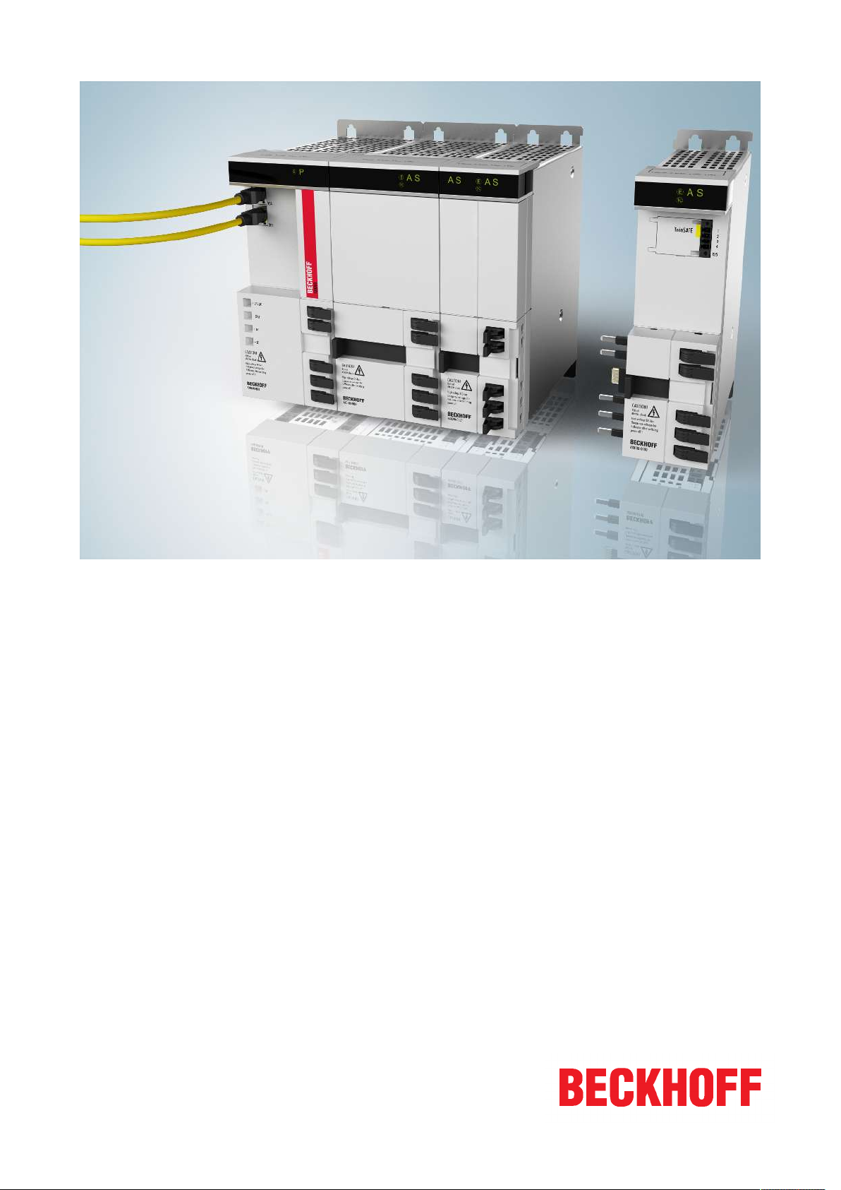
AX8911 - TwinSAFE Drive Option
TwinSAFE Drive Option for AX8xxx-x1xx Servo Drives
Version:
Date:
1.0.0
2017-10-26
Page 2

Page 3

Table of contents
Table of contents
1 Foreword ....................................................................................................................................................5
1.1 Notes on the documentation........................................................................................................... 5
1.2 Safety instructions .......................................................................................................................... 6
1.2.1 Delivery state .....................................................................................................................6
1.2.2 Operator's obligation to exercise diligence ........................................................................6
1.2.3 Description of safety symbols ............................................................................................7
1.3 Documentation issue status............................................................................................................ 7
2 References .................................................................................................................................................8
3 System description ...................................................................................................................................9
3.1 The AX8000 multi-axis servo system ............................................................................................. 9
4 Product description.................................................................................................................................10
4.1 General description....................................................................................................................... 10
4.1.1 AX8911 with STO function (AX8xxx-x1xx).......................................................................10
4.1.2 AX8911 with Safe Motion functions (AX8xxx-x2xx) .........................................................11
4.2 Intended use ................................................................................................................................. 11
4.3 Technical data .............................................................................................................................. 14
4.4 Safety parameters ........................................................................................................................ 15
4.5 Project design limits for AX8911 (AX8xxx-x1xx)........................................................................... 16
5 Operation..................................................................................................................................................17
5.1 Environmental conditions.............................................................................................................. 17
5.2 Installation..................................................................................................................................... 17
5.2.1 Safety instructions............................................................................................................17
5.2.2 Transport / storage...........................................................................................................17
5.2.3 Mechanical installation.....................................................................................................17
5.2.4 Electrical installation.........................................................................................................18
5.3 Configuration of the option in TwinCAT ........................................................................................ 20
5.3.1 Adding an axis module.....................................................................................................20
5.3.2 Using the AX8911 with the default project .......................................................................20
5.3.3 Use of the AX8911 with a fail-safe user program ............................................................24
5.3.4 Creation of safety functions .............................................................................................30
6 Use of the STO function..........................................................................................................................31
6.1 Default STO function in the AX8911............................................................................................. 33
6.1.1 Process image of the AX8xxx-x1xx .................................................................................35
6.1.2 Error reaction ...................................................................................................................35
7 Implementation of Safe Motion functions .............................................................................................36
7.1 Safe inputs and outputs ................................................................................................................ 36
7.2 Safety function STO...................................................................................................................... 36
7.3 Safety function SS1 ...................................................................................................................... 36
7.4 Safety function SS2 ...................................................................................................................... 36
7.5 Safety function SOS ..................................................................................................................... 36
7.6 Safety functions SLS, SSM, SSR ................................................................................................. 36
7.7 Safety function SAR...................................................................................................................... 36
7.8 Safety functions SDIp, SDIn ......................................................................................................... 36
7.9 Safety function SLI........................................................................................................................ 36
7.10 Safety functions SLP, SCA ........................................................................................................... 36
AX8911 - TwinSAFE Drive Option 3Version: 1.0.0
Page 4

Table of contents
8 Diagnostics ..............................................................................................................................................37
8.1 Diagnostic display of the AX8xxx axis module ............................................................................. 37
8.2 AX8xxx Diag history tab................................................................................................................ 37
8.3 Diagnosis History.......................................................................................................................... 38
9 Maintenance.............................................................................................................................................41
10 Service life................................................................................................................................................42
11 Decommissioning....................................................................................................................................43
12 Appendix ..................................................................................................................................................44
12.1 Support and Service ..................................................................................................................... 44
12.2 Certificates.................................................................................................................................... 45
AX8911 - TwinSAFE Drive Option4 Version: 1.0.0
Page 5
Foreword
1 Foreword
1.1 Notes on the documentation
Intended audience
This description is only intended for the use of trained specialists in control and automation engineering who
are familiar with the applicable national standards.
It is essential that the following notes and explanations are followed when installing and commissioning
these components.
The responsible staff must ensure that the application or use of the products described satisfy all the
requirements for safety, including all the relevant laws, regulations, guidelines and standards.
Origin of the document
This documentation was originally written in German. All other languages are derived from the German
original.
Currentness
Please check whether you are using the current and valid version of this document. The current version can
be downloaded from the Beckhoff homepage at http://www.beckhoff.com/english/download/twinsafe.htm.
In case of doubt, please contact Technical Support [}44].
Product features
Only the product features specified in the current user documentation are valid. Further information given on
the product pages of the Beckhoff homepage, in emails or in other publications is not authoritative.
Disclaimer
The documentation has been prepared with care. The products described are subject to cyclical revision. For
that reason the documentation is not in every case checked for consistency with performance data,
standards or other characteristics. We reserve the right to revise and change the documentation at any time
and without prior announcement. No claims for the modification of products that have already been supplied
may be made on the basis of the data, diagrams and descriptions in this documentation.
Trademarks
Beckhoff®, TwinCAT®, EtherCAT®, Safety over EtherCAT®, TwinSAFE®, XFC® and XTS® are registered
trademarks of and licensed by Beckhoff Automation GmbH.
Other designations used in this publication may be trademarks whose use by third parties for their own
purposes could violate the rights of the owners.
Patent Pending
The EtherCAT Technology is covered, including but not limited to the following patent applications and
patents: EP1590927, EP1789857, DE102004044764, DE102007017835 with corresponding applications or
registrations in various other countries.
The TwinCAT Technology is covered, including but not limited to the following patent applications and
patents: EP0851348, US6167425 with corresponding applications or registrations in various other countries.
AX8911 - TwinSAFE Drive Option 5Version: 1.0.0
Page 6
Foreword
EtherCAT® is registered trademark and patented technology, licensed by Beckhoff Automation GmbH,
Germany
Copyright
© Beckhoff Automation GmbH & Co. KG, Germany.
The reproduction, distribution and utilization of this document as well as the communication of its contents to
others without express authorization are prohibited.
Offenders will be held liable for the payment of damages. All rights reserved in the event of the grant of a
patent, utility model or design.
Delivery conditions
In addition, the general delivery conditions of the company Beckhoff Automation GmbH & Co. KG apply.
1.2 Safety instructions
1.2.1 Delivery state
All the components are supplied in particular hardware and software configurations appropriate for the
application. Modifications to hardware or software configurations other than those described in the
documentation are not permitted, and nullify the liability of Beckhoff Automation GmbH & Co. KG.
1.2.2 Operator's obligation to exercise diligence
The operator must ensure that
• the TwinSAFE products are only used as intended (see chapter Product description);
• the TwinSAFE products are only operated in sound condition and in working order.
• the TwinSAFE products are operated only by suitably qualified and authorized personnel.
• the personnel is instructed regularly about relevant occupational safety and environmental protection
aspects, and is familiar with the operating instructions and in particular the safety instructions contained
herein.
• the operating instructions are in good condition and complete, and always available for reference at the
location where the TwinSAFE products are used.
• none of the safety and warning notes attached to the TwinSAFE products are removed, and all notes
remain legible.
AX8911 - TwinSAFE Drive Option6 Version: 1.0.0
Page 7
Foreword
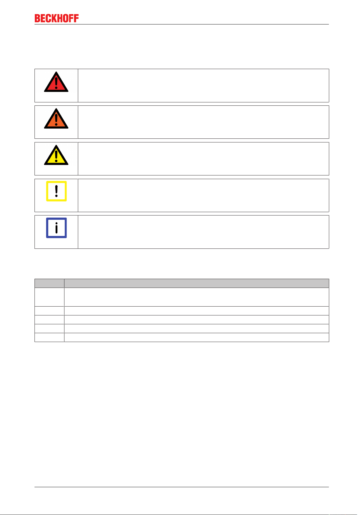
1.2.3 Description of safety symbols
In these operating instructions the following symbols are used with an accompanying safety instruction or
note. The safety instructions must be read carefully and followed without fail!
Serious risk of injury!
Failure to follow the safety instructions associated with this symbol directly endangers the
DANGER
WARNING
CAUTION
Attention
life and health of persons.
Risk of injury!
Failure to follow the safety instructions associated with this symbol endangers the life and
health of persons.
Personal injuries!
Failure to follow the safety instructions associated with this symbol can lead to injuries to
persons.
Damage to the environment or devices
Failure to follow the instructions associated with this symbol can lead to damage to the en-
vironment or equipment.
Tip or pointer
This symbol indicates information that contributes to better understanding.
Note
1.3 Documentation issue status
Version Comment
1.0.0 • Certificate added
• Description of the safe inputs and outputs added
0.4.0 • Safety parameters for the STO and SS1 functions added
0.3.0 • Description of the Safe Motion functions updated
0.2.0 • Preliminary (internal only)
0.1.0 • Preliminary (internal only)
AX8911 - TwinSAFE Drive Option 7Version: 1.0.0
Page 8

References
2 References
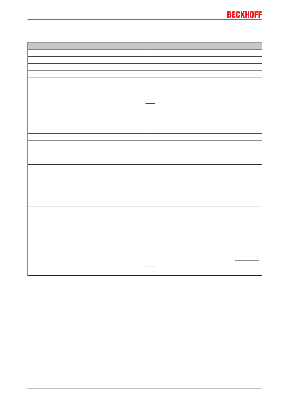
No Version Title / description
[1] 1.4.0 or newer AX8000 StartUp
This documentation contains the description of the assembly, installation
and operation of an AX8000.
[2] 1.4.1 or newer Operating instructions for EL6910 TwinSAFE logic module
The document contains a description of the logic functions of the EL6910,
and thus also of the AX8911, and their programming
[3] 3.1.0 or newer Documentation – TwinSAFE Logic FB
The document describes the safety function blocks that are available in the
EL6910, and thus also in the AX8911, and form the safety application.
[4] 1.0 or newer AX8000 system manual
Description of the mechanical and electrical parameters as well as all
information necessary for the use of the AX8000 multi-axis servo system.
[5] 1.8.0 or newer TwinSAFE application guide
The application guide provides the user with examples for the calculation of
safety parameters for safety functions according to the standards DIN EN
ISO 13849-1 and EN 62061 or EN 61508:2010, such as are typically used
on machines.
AX8911 - TwinSAFE Drive Option8 Version: 1.0.0
Page 9
System description
3 System description
3.1 The AX8000 multi-axis servo system
Multi-channel drive solutions can be constructed with the AX8000 multi-axis servo system. The required
number of single-channel or two-channel axis modules are attached to the central supply module. The
modules are connected without screws or tools using the built-in AX-Bridge quick connection system, which
is based on spring-loaded terminals. The single-axis and dual-axis modules can optionally be equipped with
STO or Safe Motion (AX8xxx-x1xx or AX8xxx-x2xx).
eXtreme Fast Control in the drive
The EtherCAT-based AX8000 multi-axis servo system combines powerful FPGA technology with multi-core
ARM processors. The new multi-channel current control technology makes extremely short sampling and
reaction times possible. The entirely hardware-implemented current controller combines the advantages of
analog and digital control technology: reaction to a deviation of the current from the setpoint value is possible
within 1 µs; the velocity controller cycle time is around 16 µs at a switching frequency of 32 kHz. The
processing of the EtherCAT process data (actual and setpoint values) can take place without a processor
almost without delay in the hardware, so that the minimum EtherCAT cycle time is only 62.5 µs.
One Cable Technology (OCT)
The AX8000 multi-axis servo system supports OCT, the one-cable solution for power and feedback. In
connection with the servo motors from the AM8000 (standard), AM8500 (increased inertia) and AM8800
(stainless steel) series, the wiring is reduced to the obligatory motor cable, via which the feedback signals
are then also directly transmitted. As in sensorless control, the user no longer has to use an additional
feedback cable. All the information required for control purposes is transferred reliably and fail-safe via a
digital interface.
AX8911 - TwinSAFE Drive Option 9Version: 1.0.0
Page 10
Product description
4 Product description
4.1 General description
AX8911 - TwinSAFE drive option for AX8000 series servo drives
The AX8911 TwinSAFE drive option is an optional extension of the Beckhoff AX8000 servo drive series.
There are two versions of the AX8911 option. The first version provides only the STO function via the digital
inputs of the AX8000 axis module or via a TwinSAFE (FSoE) connection. The second version provides STO
and additionally the Safe Motion functions such as Safe Limited Speed.
The AX8911 meets the requirements of IEC 61508:2010 SIL3, EN62061:2005/A1:2013/A2:2015SILCL3
and ENISO13849-1:2015(Cat 4, PL e).
The AX8911 is intended for use in a servo drive from the AX8000 series, in which it is permanently installed.
4.1.1 AX8911 with STO function (AX8xxx-x1xx)
Through the integration of the AX8911 drive option in the AX8000, the STO safety function can be enabled
via two digital inputs per channel of the servo drive or via Safety-over-EtherCAT (FSoE). The digital inputs
and the signals via FSoE are equivalent and are logically ORed internally. It is therefore sufficient to enable
the axis via either one of the two ways.
The respective axis is enabled if both of its digital inputs are logic 1 (24VDC). If at least one of the two digital
inputs is logic 0, then the STO safety function is active and the motor is switched torque-free.
Alternatively, the STO function of the axis can be accessed via Safety-over-EtherCAT (FSoE). The
respective axis is enabled if the STO signal via FSoE is logic 1. If the STO signal via FSoE is logic 0, the
STO safety function is active and the motor is switched torque-free.
The AX8911 drive option is typically addressed via FSoE. The digital inputs are intended for the
commissioning of the AX8000. It is also possible via the digital inputs to operate the AX8911 drive option
with a safety controller that doesn't support the FSoE protocol.
Digital inputs and Safety-over-EtherCAT (FSoE)
If you use the FSoE connection for accessing the AX8911 drive option and additionally the
Attention
digital inputs of the AX8000 on X15 or X25 during the commissioning of the axis, make
sure that the wiring to the digital inputs is removed after the commissioning of the axis.
STO function
If the STO function described above is not suitable for the application, it must be changed
Note
by the user or by loading a user-defined safety project into the AX8911.
AX8911 - TwinSAFE Drive Option10 Version: 1.0.0
Page 11
Product description
4.1.2 AX8911 with Safe Motion functions (AX8xxx-x2xx)
Through the integration of the AX8911 into the AX8000, the user can implement safety functions in
accordance with the following list:
• Stop functions such as STO, SOS, SS1, SS2
• Speed functions such as SLS, SSM, SSR
• Acceleration functions such as SAR
• Direction of rotation functions such as SDIp, SDIn
• Position functions such as SLP, SCA, SLI (however, SLP and SCA are possible only if an appropriate
safe feedback system is used)
Like the programming or configuration of the safety application, the entire parameterization of the AX8911
option card is performed from the TwinCAT software. All system-specific settings are stored together with the
application in the AX8911. The backup/restore mechanism familiar from the EL69x0 can be used for the
exchange of the AX8911. Further information on this can be found in the EL6910 user documentation (see
References [}8]).
4.2 Intended use
The AX8911 TwinSAFE drive option card extends the field of use of the Beckhoff AX8000 servo drive by
safety functions that allow it to also be used in the field of machine safety.
Observe the intended use!
Use of the TwinSAFE drive option card other than for the intended purpose as described
WARNING
The AX8911 card can be addressed as a TwinSAFE drive option card via the TwinSAFE inputs X15 or X25
or via an FSoE or TwinSAFE connection. Depending on which of these variants is used, the error reactions
of the TwinSAFE drive option card described below may be different.
The following safety measures and safety instructions must be observed when using the TwinSAFE
drive option card
General notes
below is not permitted!
Power supply from SELV/PELV power supply unit!
The TwinSAFE components must be supplied with 24VDC by an SELV/PELV power supply
WARNING
unit with an output voltage limit U
safety.
of 36VDC. Failure to observe this can result in a loss of
max
Caution - Risk of injury!
Basically, electronic devices are not fail-safe. The machine manufacturer is responsible for
WARNING
ensuring that the connected motors and the machine are brought into a safe state in the
event of a voltage outage in the drive system
Follow the machinery directive!
The TwinSAFE Drive option cards may be used in machines only as defined in the machine
CAUTION
directive.
Ensure traceability!
The buyer has to ensure the traceability of the device via the serial number.
CAUTION
AX8911 - TwinSAFE Drive Option 11Version: 1.0.0
Page 12

Product description
Parameterization
Check the parameterization of the TwinSAFE drive option card!
The TwinSAFE drive option card determines errors in the parameterization, but no logical
WARNING
testing of the parameters or the loaded safety program can take place. Hence, you must
ensure by means of an acceptance test that the parameterization and the safety program
are correct for the application. This test must be performed by the machine manufacturer.
The combination of AX8000 and AX8911 may be used in production only when this test
has produced a positive result for all safety-relevant functions.
Avoid incorrect parameterization of the servo drive!
Incorrect parameterization of the servo drive (e.g. current controller oscillates or is too
WARNING
lethargic) can lead to switch-off. The AX8911 switches the motors of the AX8000 servo
drive torque-free. Any motors that are still moving coast to a halt. With suspended or pulling
loads the motors may also accelerate. External safety measures (e.g. mechanical service
brakes) are to be provided by the user to avoid unwanted movements.
Avoid incorrect dimensioning of the servo drive!
Loads that cannot be braked by the AX8000 servo drive (e.g. if the AX8000 servo drive is
WARNING
under-dimensioned) can lead to switch-off. The AX8911 switches the motors of the AX8000
servo drive torque-free. Any motors that are still moving coast to a halt. With suspended or
pulling loads the motors may also accelerate. External safety measures (e.g. mechanical
service brakes) are to be provided by the user to avoid unwanted movements.
External safety measures
Provide for external safety measures for the STO function of the TwinSAFE
drive option card!
WARNING
If the STO safety function is executed, the connected motors are not braked, but are
switched torque-free. This leads to the motors coasting to a halt. The duration of this coasting depends on how much kinetic energy is present in the system. With suspended or
pulling loads the motors may also accelerate. The user must provide appropriate external
safety measures (e.g. mechanical service brakes) to prevent this.
Provide for external safety measures for the error reactions of the TwinSAFE
drive option card!
WARNING
The STO error reaction is executed if the TwinSAFE drive option card determines an error.
If the STO error reaction is executed, the connected motors are not braked, but are directly
switched torque-free. This leads to the motors coasting to a halt. The duration of this coasting depends on how much kinetic energy is present in the system. With suspended or
pulling loads the motors may also accelerate. The user must provide appropriate external
safety measures (e.g. mechanical service brakes) to prevent this.
AX8911 - TwinSAFE Drive Option12 Version: 1.0.0
Page 13

Diagnostics / faults
Avoid line interruptions!
Line interruptions can lead to switch-off. The AX8911 can switch the motors of the AX8000
WARNING
servo drive torque-free according to the safety project used on it. Any motors that are still
moving coast to a halt. With suspended or pulling loads the motors may also accelerate.
External safety measures (e.g. mechanical service brakes) are to be provided by the user
to avoid unwanted movements.
Avoid faults and interruptions in the EtherCAT communication!
Faults and interruptions in the EtherCAT communication lead to switch-off. The AX8911
WARNING
can switch the motors of the AX8000 servo drive torque-free according to the safety project
used on it. Any motors that are still moving coast to a halt. With suspended loads the motors may even be accelerated. External safety measures (e.g. mechanical service brakes)
are to be provided by the user to avoid unwanted movements.
Activation or restart of a project in TwinCAT
The activation or restart of a project in TwinCAT can lead to switch-off. The AX8911 can
WARNING
switch the motors of the AX8000 servo drive torque-free according to the safety project
used on it. Any motors that are still moving coast to a halt. With suspended loads the motors may even be accelerated. External safety measures (e.g. mechanical service brakes)
are to be provided by the user to avoid unwanted movements.
Product description
WARNING
Downloading the safety project to the TwinSAFE logic or the AX8911 can
lead to switch-off!
Downloading the safety project to the TwinSAFE logic or the AX8911 can lead to switch-off.
The AX8911 switches the motors of the AX8000 servo drive torque-free. Any motors that
are still moving coast to a halt. With suspended or pulling loads the motors may also accelerate. External safety measures (e.g. mechanical service brakes) are to be provided by the
user to avoid unwanted movements.
AX8911 - TwinSAFE Drive Option 13Version: 1.0.0
Page 14
Product description
4.3 Technical data
Product designation AX8911 (AX8xxx-x1xx)
Number of inputs 2 digital inputs per channel (X15, X25)
Status display "S" display on the AX8000
Minimum/maximum cycle time approx. 1 ms / according the project size
Fault response time ≤ watchdog times
Watchdog time min. 2 ms, max. 60000 ms
Supply voltage (SELV/PELV) 24VDC (–10% /+10%)
refer also to the AX8000 Startup manual (References
[}8])
Dimensions (W x H x D) integrated in the AX8xxx-x1xx
Weight approx. 25g
Permissible ambient temperature (operation) 0 °C to +55 °C
Permissible ambient temperature (transport/storage) -25 °C to +70 °C
Permissible air humidity 5% to 95%, non-condensing
Permissible air pressure (operation/storage/transport) 750hPa to 1100hPa
(this corresponds to an altitude of approx. -690m to
2450m above sea level, assuming an international
standard atmosphere)
Climate category according to EN 60721-3-3 3K3
(the deviation from 3K3 is possible only with optimal
environmental conditions and also applies only to the
technical data which are specified differently in this
documentation)
Permissible level of contamination according to
EN60664-1
Inadmissible operating conditions TwinSAFE drive option cards may not be used under
Correct installation position
Approvals CE, TÜV SÜD
level of contamination 2
the following operating conditions:
• under the influence of ionizing radiation
(exceeding the natural background radiation)
• in corrosive environments
• in an environment that leads to impermissible
contamination of the option card
refer also to the AX8000 Startup manual (References
[}8])
AX8911 - TwinSAFE Drive Option14 Version: 1.0.0
Page 15
4.4 Safety parameters
Safety functions STO, SS1
Characteristic numbers AX8911 - STO, SS1 (AX8xxx-x1xx)
Lifetime [a] 20
Proof test interval [a] not required
PFH
D
%SIL3 of PFH
PFD
avg
%SIL3 of PFD
MTTF
D
D
avg
3.04E-09
3% of SIL3
9.20E-05
9% of SIL3
high
DC high, 99.5%
SFF >99%
Performance level PL e
Category 4
HFT 1
Classification element
2)
Type B
1)
Product description
1. Special proof tests are not required during the entire service life of the AX8911 TwinSAFE drive option
card.
2. Classification according to IEC61508-2:2010 (see chapters 7.4.4.1.2 and 7.4.4.1.3)
The AX8911 TwinSAFE drive option card can be used for safety-related applications within the meaning of
IEC61508:2010 up to SIL3, EN62061:2005/A1:2013/A2:2015 up to SILCL3 and ENISO13849-1:2015 up
to PL e (Cat.4).
Further information on calculating or estimating the MTTFD value from the PFHD value can be found in the
TwinSAFE application guide or in ENISO13849-1:2015, TableK.1.
In terms of safety-related parameters, the Safety-over-EtherCAT communication is already considered with
1% of SIL3 according to the protocol specification.
Safe Motion functions SS2, SOS, SLS, SLP
The safety parameters for the Safe Motion functions are inserted here as soon as the AX8xxx-x2xx devices
with AX891x safety option card are enabled.
AX8911 - TwinSAFE Drive Option 15Version: 1.0.0
Page 16

Product description
4.5 Project design limits for AX8911 (AX8xxx-x1xx)
Project design limits
The maximum project design size of the AX8911 (AX8xxx-x1xx) is limited by the available
Note
TwinSAFE connections max. 8
Safe data per TwinSAFE
connection
TwinSAFE blocks maximum 512 (ESTOP with complete input and output mapping)
TwinSAFE groups max. 128
TwinSAFE user 40 max.
Standard PLC inputs dynamic (memory-dependent), max. 54byte
Standard PLC outputs dynamic (memory-dependent), max. 62byte
memory. This is managed dynamically. The values specified in the following table are
therefore only guide values and may differ from the actual values, depending on the safety
project.
(up to 12 CRCs in total; 1 CRC is required for a TwinSAFE connection
with 1 or 2 byte safe data.)
maximum 24byte (telegram length 51byte)
AX8911 - TwinSAFE Drive Option16 Version: 1.0.0
Page 17

Operation
5 Operation
5.1 Environmental conditions
Please ensure that the TwinSAFE components are only transported, stored and operated under the specified
conditions (see technical data)!
Risk of injury!
The TwinSAFE components must not be used under the following operating conditions.
WARNING
Attention
• under the influence of ionizing radiation (that exceeds the level of the natural environmental radiation)
• in corrosive environments
• in an environment that leads to unacceptable soiling of the TwinSAFE component
Electromagnetic compatibility
The TwinSAFE components comply with the current standards on electromagnetic compatibility with regard to spurious radiation and immunity to interference in particular.
However, in cases where devices such as mobile phones, radio equipment, transmitters or
high-frequency systems that exceed the interference emissions limits specified in the standards are operated near TwinSAFE components, the function of the TwinSAFE components may be impaired.
5.2 Installation
Installation note
Please also refer to the installation notes on the mechanical and electrical installation of the
Note
5.2.1 Safety instructions
Before installing and commissioning the TwinSAFE components please read the safety instructions in the
foreword of this documentation.
5.2.2 Transport / storage
For transport and storage of the AX8xxx with the AX8911 TwinSAFE drive option card, use the original
packaging in which the components were delivered.
CAUTION
AX8000 in the AX8000 StartUp manual.
Observe the specified environmental conditions
Please ensure that the digital TwinSAFE components or the AX8000 with AX8911 TwinSAFE drive option card are only transported and stored under the specified environmental
conditions (see technical data).
5.2.3 Mechanical installation
The AX8911 TwinSAFE drive option is permanently installed in the AX8000 servo drive. Subsequent
installation or exchange of the option by the user is not possible.
AX8911 - TwinSAFE Drive Option 17Version: 1.0.0
Page 18

Operation
5.2.3.1 Control cabinet / terminal box
The TwinSAFE components must be installed for operation in a control cabinet or terminal box with at least
IP54 protection according to IEC60529.
5.2.4 Electrical installation
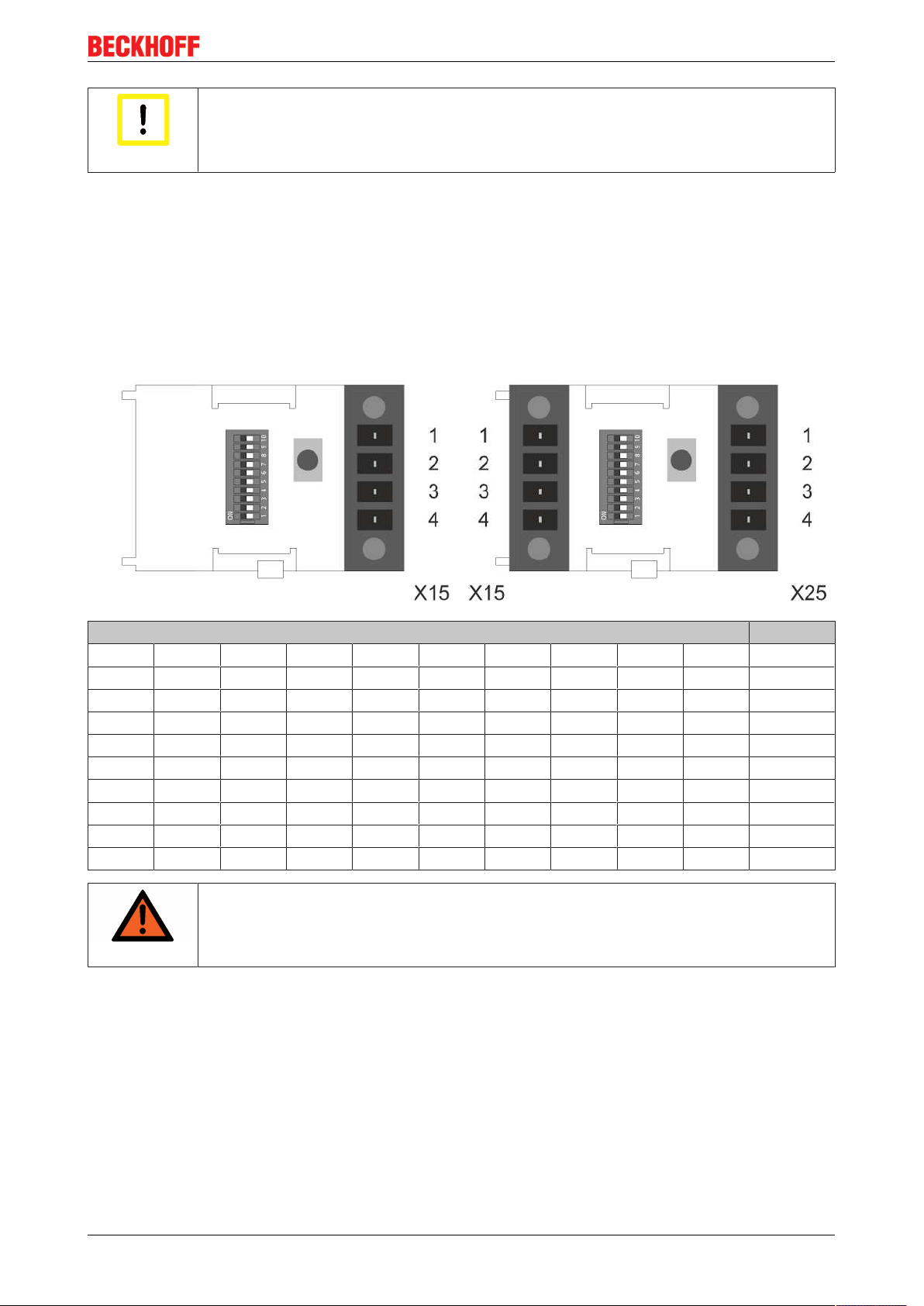
5.2.4.1 Digital inputs X15, X25
With the AX8911 TwinSAFE drive option installed, the inputs X15 (axis "A") and X25 (axis "B") are used for
the STO inputs of the axis or axes.
Contacts 1 and 2 of the connection X15 are the STO inputs for axis "A". Axis "A" can be moved if both
signals are logic 1 (24 VDC). STO is triggered for axis "A" if one of the signals is logic 0. Axis "A" is switched
torque-free.
Contacts 1 and 2 of the connection X25 are the STO inputs for axis "B". Axis "B" can be moved if both
signals are logic 1 (24 VDC). STO is triggered for axis "B" if one of the signals is logic 0. Axis "B" is switched
torque-free.
Fig.1: AX8911: Connection to X15 and X25
A plug connector is required in each case to connect signals to X15 and, in the case of two-channel axis
modules, to X25 also.
View Terminal
point
1 STO input 1 9 mm push in
2 STO input 2
3 Digital input 3
4 Digital input 4
Wire type Wire cross-section
Wire cross-section (solid wire) 0.14 mm² - 1.5 mm²
Wire cross-section (fine wire) 0.14 mm² - 1.5 mm²
Wire cross-section – fine wire (with ferrule without plastic collar) 0,25 mm² - 1.5 mm²
Wire cross-section – fine wire (with ferrule with plastic collar) 0,25 mm² - 1 mm²
Connection Strip length Clamping method
(Filter time 8 µs)
(Filter time 8 µs)
AX8911 - TwinSAFE Drive Option18 Version: 1.0.0
Page 19
Operation
Wiring
Wires with ferrules with plastic collars must be used when using the STO safety function via
Attention
the STO inputs on X15 and X25.
5.2.4.2 Setting the TwinSAFE address
If a TwinSAFE connection is used instead of the digital inputs for the implementation of the safety functions
or selection of the STO function, a safety address must be set on the axis module.
This setting is made with the integrated DIP switch on the AX8000 axis module, which is located under the
cover between the X15 and X25 inputs or, in the case of single-axis modules, to the left of X15.
AX81xx-x1xx single-axis module AX82xx-x1xx dual-axis module
DIP switch Address
1 2 3 4 5 6 7 8 9 10
ON OFF OFF OFF OFF OFF OFF OFF OFF OFF 1
OFF ON OFF OFF OFF OFF OFF OFF OFF OFF 2
ON ON OFF OFF OFF OFF OFF OFF OFF OFF 3
OFF OFF ON OFF OFF OFF OFF OFF OFF OFF 4
ON OFF ON OFF OFF OFF OFF OFF OFF OFF 5
OFF ON ON OFF OFF OFF OFF OFF OFF OFF 6
ON ON ON OFF OFF OFF OFF OFF OFF OFF 7
... ... ... ... ... ... ... ... ... ... ...
ON ON ON ON ON ON ON ON ON ON 1023
TwinSAFE address
Each TwinSAFE address may only be used once within a network/ a configuration!
WARNING
The address 0 is not a valid TwinSAFE address!
AX8911 - TwinSAFE Drive Option 19Version: 1.0.0
Page 20
Operation
5.3 Configuration of the option in TwinCAT
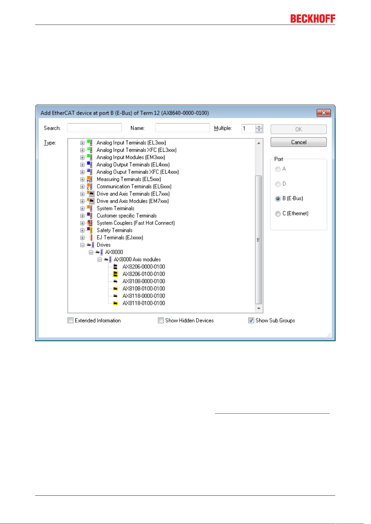
5.3.1 Adding an axis module
When adding an axis module in TwinCAT 3, a distinction is made between a module with TwinSAFE drive
option and a module without TwinSAFE drive option. After adding a supply module, an axis module can be
added under the Drives category.
Fig.2: Addition of an axis module
In addition to the manual creation of the configuration, it can also be created by scanning the EtherCAT line.
5.3.2 Using the AX8911 with the default project
The AX8911 TwinSAFE drive option, with which an STO function can be implemented, is installed in the
AX8xxx-x1xx devices. Information on this project can be found in Default STO function in the AX8911 [}33].
To use the AX8911 in a project (e.g. EL6910), add an Alias Device AX891x(SafeDriveModule).
AX8911 - TwinSAFE Drive Option20 Version: 1.0.0
Page 21
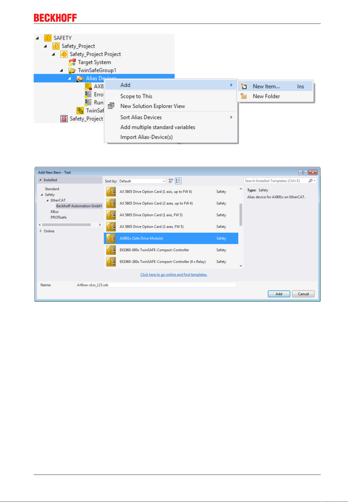
Fig.3: Addition of an alias device
Operation
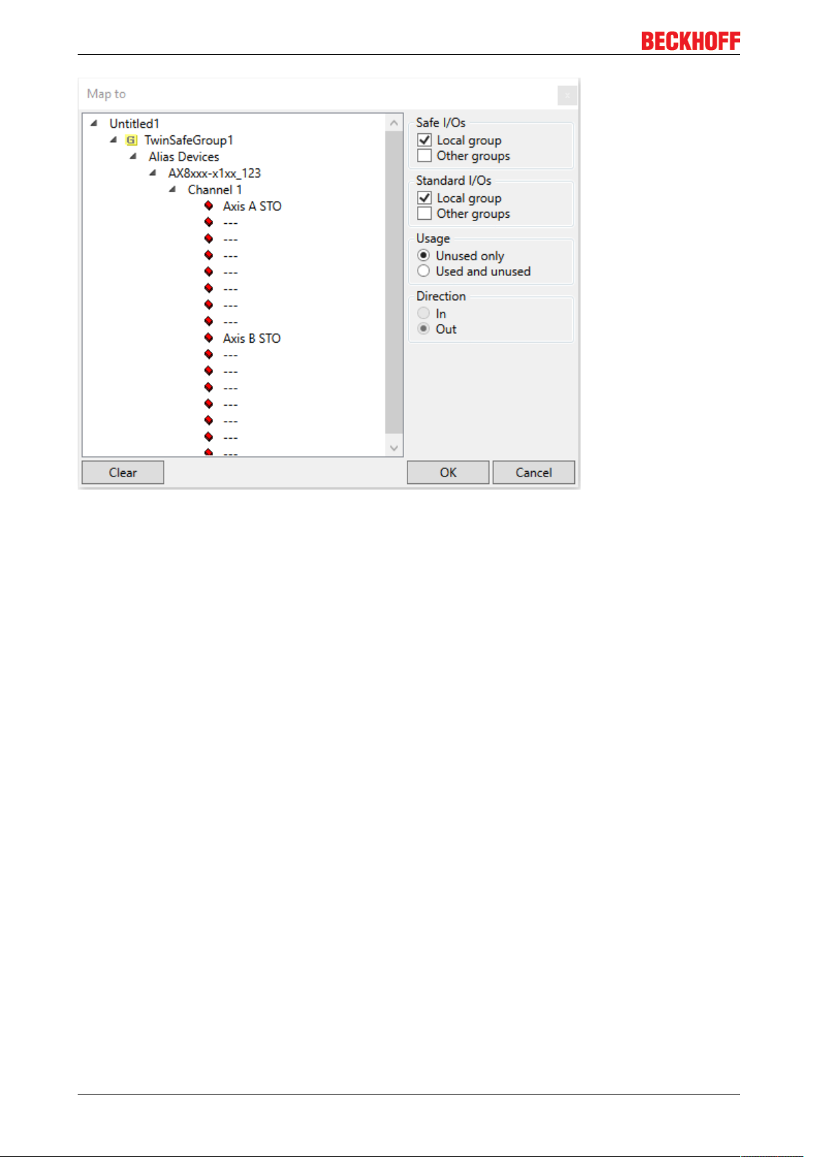
Fig.4: Dialog Add new item AX891x (Safe Drive Module)
The STO signals can be used as safe outputs in the fail-safe user program.
AX8911 - TwinSAFE Drive Option 21Version: 1.0.0
Page 22
Operation
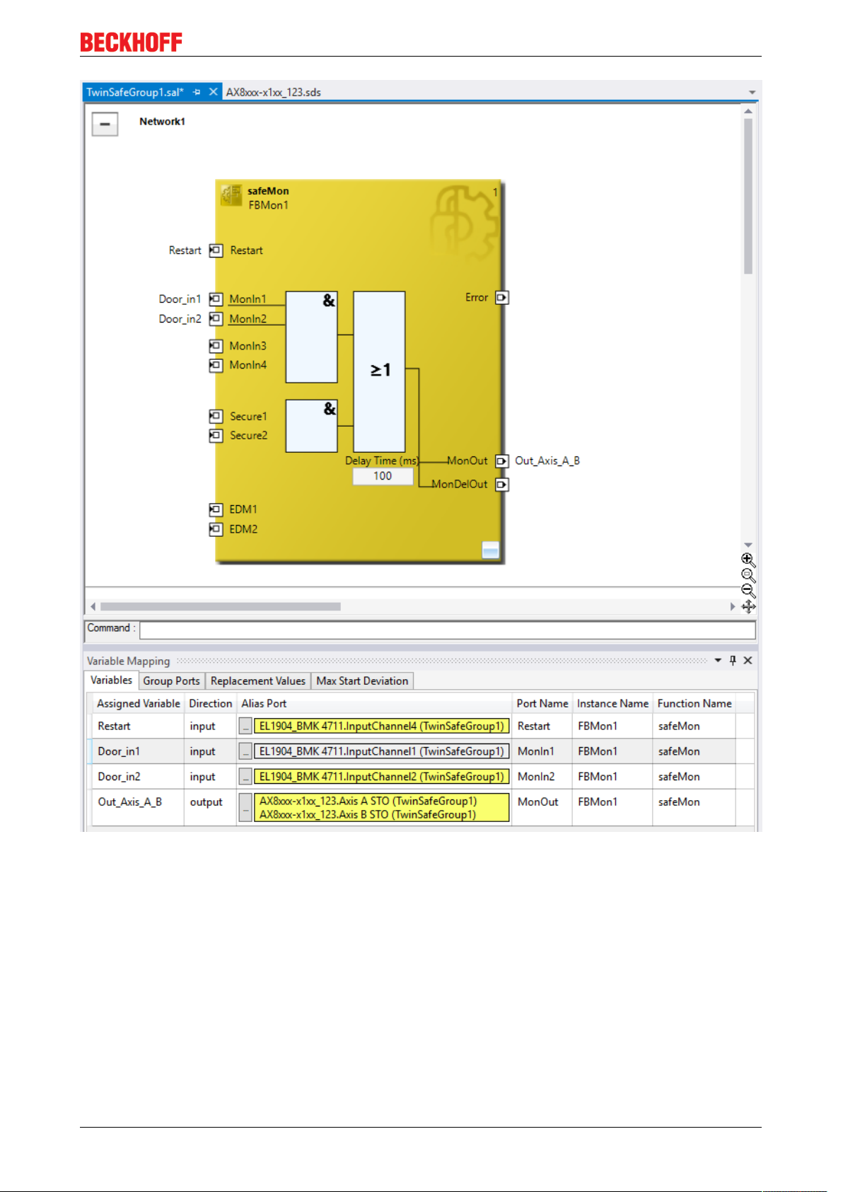
Fig.5: Dialog for linking the variables of the AX8911
The variables are displayed with the corresponding designation in Variable Mapping.
AX8911 - TwinSAFE Drive Option22 Version: 1.0.0
Page 23
Operation
Fig.6: Projects with outputs to the AX8911
AX8911 - TwinSAFE Drive Option 23Version: 1.0.0
Page 24
Operation
5.3.3 Use of the AX8911 with a fail-safe user program
Target system
For the use of the user-specific functions in the AX8911, a safety project is created in TwinCAT and the
AX8911 or the axis module is selected as the target system.
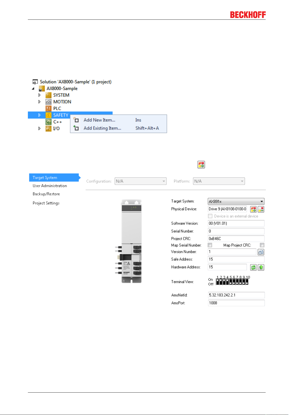
A safety project is added by right-clicking on the safety node and selecting Add new item...
Fig.7: Add new item
The target system can be selected by double-clicking on the subentry Target System. The AX891x is
selected here in the drop-down list and linked with the axis module using the button.
Fig.8: Target system AX8911
In order to be able to use the inputs and outputs of the AX8911, an alias device AX891x (Safe Drive Module)
must be added in the safety application and set to local under Linking Mode.
AX8911 - TwinSAFE Drive Option24 Version: 1.0.0
Page 25
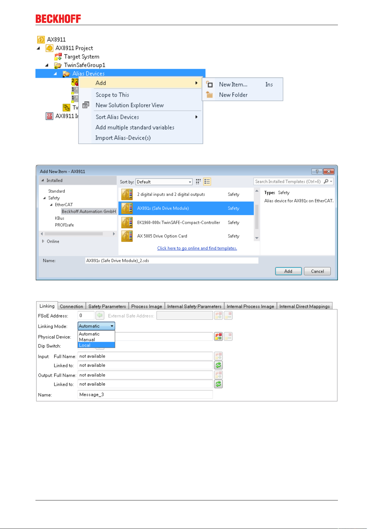
Fig.9: AX8911 - Add new item
Operation
Fig.10: AX8911 - Add new item - Alias Device AX891x
Fig.11: AX8911 - Linking Mode local
After changing the linking mode to local, all alias device settings that are not relevant are shown as disabled
for input.
AX8911 - TwinSAFE Drive Option 25Version: 1.0.0
Page 26

Operation
Safe inputs and outputs within the safety logic
The local inputs and outputs of the AX8911 and their meaning are listed in the following tables.
Fig.12: AX8911 – safe inputs of the local alias device
AX8911 - TwinSAFE Drive Option26 Version: 1.0.0
Page 27

Operation
Input (for each axis A and B) Data type Meaning
FSOUT STO Module Fault BOOL STO module fault
FSOUT BRAKE Module Fault BOOL currently not used
(Brake module fault)
FSOUT BRAKE Active BOOL currently not used
(Activate brake)
FSIN Channel1.Input BOOL Digital input 1 to X15 or X25 respectively
FSIN Channel2.Input BOOL Digital input 2 to X15 or X25 respectively
FSIN Module Fault BOOL Input module fault
FSDRIVE Underrange Encoder
Voltage
FSDRIVE Overrange Encoder
Voltage
FSDRIVE Module Fault BOOL Drive module fault
FSDRIVE Encoder Enable BOOL currently not used
FSDRIVE Run BOOL Run signal from AX8000 – can be used for the group
FSDRIVE ErrAck BOOL Error Acknowledge Signal from AX8000 – can be used for
FSDRIVE Control 2-15 BOOL not used
BOOL The encoder supply voltage is too low
BOOL The encoder supply voltage is too high
(Activate encoder)
inputs
the group inputs and for the ErrAck outputs to reset
module faults (executed together with an axis reset).
AX8911 - TwinSAFE Drive Option 27Version: 1.0.0
Page 28

Operation
Fig.13: AX8911 – safe outputs of the local alias device
AX8911 - TwinSAFE Drive Option28 Version: 1.0.0
Page 29

Output (for each axis A andB)Data type Meaning
Operation
FSOUT STO
Channel1.Output
FSOUT STO
Channel2.Output
FSOUT STO
Channel3.Output
FSOUT STO
Channel4.Output
FSOUT STO ErrAck BOOL Acknowledgment of a module fault in the STO module
FSOUT STO STO Active BOOL Information sent to the AX8000 about the state of the STO
FSOUT BRAKE PWM Output BOOL PWM signal for controlling the brake
FSOUT BRAKE Digital Output BOOL Enable signal for the brake control
FSOUT BRAKE ErrAck BOOL Acknowledgment of a module fault in the BRAKE module
FSIN ErrAck BOOL Acknowledgment of a module fault in the FSIN module
FSDRIVE ErrAck BOOL Acknowledgment of a module fault in the FSDRIVE module
FSDRIVE Group Error BOOL Status information about a group error for the AX8000
FSDRIVE Axis STO Error BOOL Status information about an STO error for the AX8000
FSDRIVE Axis Digital Input
Error
FSDRIVE Axis Brake Error BOOL Status information about a brake error for the AX8000
FSDRIVE Encoder
Undervoltage Error
FSDRIVE Encoder
Overvoltage Error
FSDRIVE Encoder Enabled BOOL Status information sent to the AX8000 about whether the encoder
FSDRIVE Status 7-13 BOOL not used
FSDRIVE FSIN Test pulse
Channel1
FSDRIVE FSIN Test pulse
Channel2
BOOL STO switch-off path A
(all four switch-off paths and STO Active must be set to logic 1 in
order to enable the axis and to logic 0 for the STO function)
BOOL STO switch-off path B
(all four switch-off paths and STO Active must be set to logic 1 in
order to enable the axis and to logic 0 for the STO function)
BOOL STO switch-off path C
(all four switch-off paths and STO Active must be set to logic 1 in
order to enable the axis and to logic 0 for the STO function)
BOOL STO switch-off path D
(all four switch-off paths and STO Active must be set to logic 1 in
order to enable the axis and to logic 0 for the STO function)
(In the default project this signal is linked with the FSDRIVE
ErrAck input)
function. Must be set to logic 1 so that the AX8000 will enable the
axis.
(In the default project this signal is linked with the FSDRIVE
ErrAck input)
(In the default project this signal is linked with the FSDRIVE
ErrAck input)
(In the default project this signal is linked with the FSDRIVE
ErrAck input)
BOOL Status information about an input error for the AX8000
BOOL Status information about an undervoltage error for the AX8000
BOOL Status information about an overvoltage error for the AX8000
is active. (not used so far)
BOOL used internally to test input 1 on X15 or X25 respectively. Cannot
be used by the user.
BOOL used internally to test input 2 on X15 or X25 respectively. Cannot
be used by the user.
AX8911 - TwinSAFE Drive Option 29Version: 1.0.0
Page 30

Operation
5.3.4 Creation of safety functions
The creation of a fail-safe user program is explained in the documentation for the EL6910 and the FB
description. The corresponding documents are listed under References [}8].
Switching back to the default project
If the entire project (safe logic, parameters and mapping) is deleted on the AX8911 Twin-
Note
SAFE drive option, the default project will be active again after restarting the AX8911.
AX8911 - TwinSAFE Drive Option30 Version: 1.0.0
Page 31

6 Use of the STO function
Restart lock
The restart lock is to be implemented in the higher-level safety controller.
CAUTION
CAUTION
CAUTION
Note
Alternatively, this can be adapted by the user or the machine manufacturer by modifying
the fail-safe program on the AX8911.
OSSD signals on X15 and X25
The test pulses must not exceed a length of 3.5 ms. Longer test pulses can lead to triggering of the STO.
Alternatively, this can be adapted by the user or the machine manufacturer by modifying
the fail-safe program on the AX8911.
Cross-circuits / external power supply
The higher-level safety controller is responsible for checking the wiring between the safety
controller and the TwinSAFE inputs of the AX8911 (X15, X25). The necessary tests and
checks arise from the risk and hazard analysis carried out by the machine manufacturer.
Testing the X15 and X25 inputs
The functions of the STO inputs 1 and 2 of the connections X15 or X25 are tested internally
by the AX8911 TwinSAFE drive option card. The external test pulses for detecting crosscircuits or an external power supply serve only to check the correct wiring between the
safety controller and the TwinSAFE drive option card.
Use of the STO function
Using the STO inputs with TwinSAFE outputs
In this application case the STO inputs 1 and 2 of the digital inputs X15 and, if applicable, X25 are wired
directly to safe outputs, for example of an EL2904. When using the EL2904, the safe outputs are
parameterized in such a way that the test pulses are active, but the parameter Current Measurement active
is disabled. If other TwinSAFE outputs are used they must also be parameterized in the same way so that
test pulses are active at the output.
A filter is implemented within the logic of the AX8911 (default 3.5 ms) so that the test pulses of, for example,
the EL2904 cannot lead to a switch-off of the STO channels.
Fig.14: TwinSAFE outputs connected to STO inputs
AX8911 - TwinSAFE Drive Option 31Version: 1.0.0
Page 32
Use of the STO function
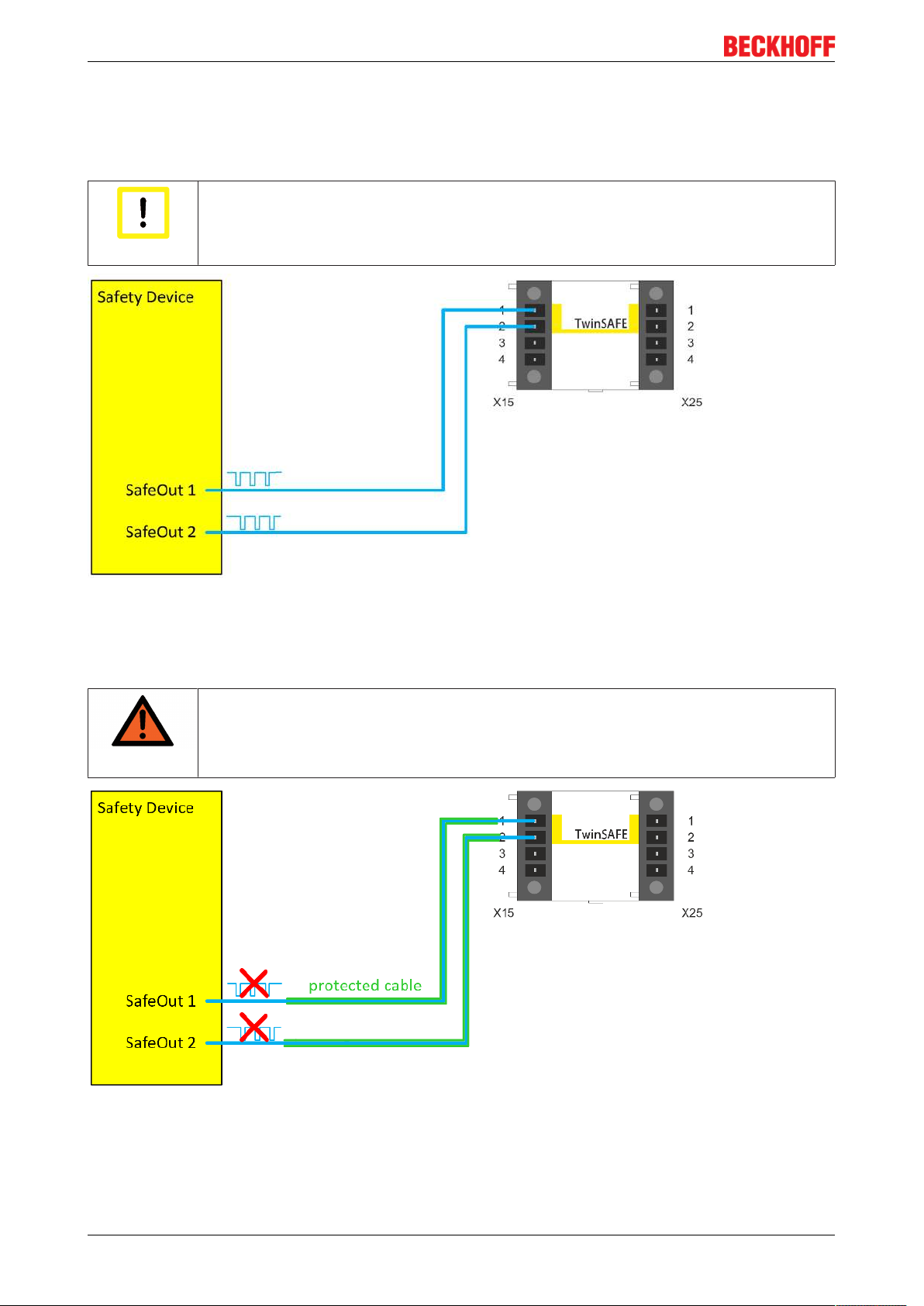
Using the STO inputs with a third-party safety controller
It must also be ensured that test pulses are generated when using a third-party safety controller or safe
output. The user must ensure that the test pulse length and frequency do not lead to a switch-off of the STO
channels or the AX8911. A filter with a filter time of 3.5 ms is implemented within the logic of the AX8911.
Safety assessment
When using a third-party safety controller, the safety assessment must be carried out by
Attention
the user or the machine manufacturer.
Fig.15: Safe outputs from a third-party manufacturer connected to STO inputs
If the safety controller is unable to implement test pulses at the outputs, but instead supplies only static
24VDC signals, the user must implement the wiring in such a way that a fault exclusion is permitted for the
wiring. Further information about fault exclusions can be found in ENISO13849-2.
protected wiring
If no test pulses are used on the signals between the outputs of the safety controller and
WARNING
the STO inputs of the AX8xxx-x1xx, the wiring must be implemented in the form of protected cable laying (see also EN ISO 13849-2).
Fig.16: Safe outputs from a third-party manufacturer connected to STO inputs without the use of test pulses
AX8911 - TwinSAFE Drive Option32 Version: 1.0.0
Page 33
Use of the STO function
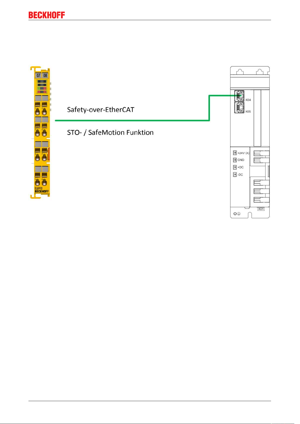
Use of the STO function via a TwinSAFE (FSoE) connection
Additional wiring of the STO inputs is unnecessary if the AX8911 is connected to a TwinSAFE logic via
EtherCAT and the Safety-over-EtherCAT protocol. Here, the signals of the connection to, for example, an
EL6910 are used in the AX8911 logic in order to switch off the STO channels and the brake controller of the
AX8911.
Fig.17: STO function via TwinSAFE connection
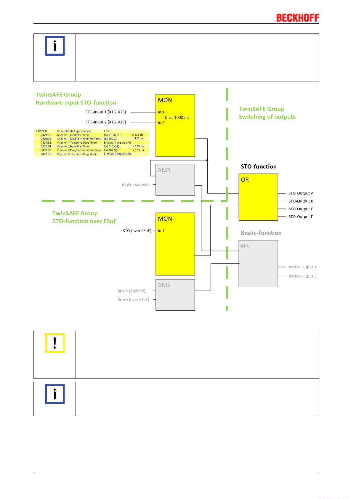
6.1 Default STO function in the AX8911
A fail-safe logic program is stored on the AX8911 in the delivery state. There are two different ways to
activate the STO function.
• The hardware inputs on X15 and X25
The input signals are filtered (external test pulses up to a length of 3.5 ms are supported) and tested
for discrepancy. A logic TRUE of both signals allows movement of the axis.
The discrepancy time for the two input signals is set to 1000 ms. If the two signals are different for a
lengthy time, an error is signaled and a diagnostic message output.
• A TwinSAFE or Safety-over-EtherCAT connection
This connection contains the STO signals for axis A and axis B. For the STO signal a logic TRUE
signal is required so that movement of the axis is possible. The safety address for this connection is set
with the DIP switch of the AX8000 axis module.
The outputs of the two groups are logically ORed and then placed on the four STO channels. The groups are
implemented equivalently in the default application i.e. if one group supplies information that the axis may be
moved, then this is sufficient.
AX8911 - TwinSAFE Drive Option 33Version: 1.0.0
Page 34
Use of the STO function
Hardware inputs / TwinSAFE signals
Hardware inputs and signals via the TwinSAFE connection are equivalent. If one of the two
Note
supplies the enable signal to move the axis, the axis can be moved.
If this does not suit the functionality desired by the user, the fail-safe program on the
AX8911 can be replaced by the user or the machine manufacturer with a program suitable
for the application case.
Fig.18: Default TwinSAFE logic program for AX8911
Brake control
Brake control currently takes place only by the AX8000 in accordance with the parameteri-
Attention
zation in the TC3 Drive Manager 2. The brake output is generally enabled in the AX8911
firmware. The default TwinSAFE logic program shown above is implemented accordingly
on the AX8911; however, the brake outputs 1 and 2 currently have no effect. The Brake
(over FSoE) signal does not exist in the TwinSAFE connection.
STO switch-off paths
There are four STO switch-off paths per axis within the logic (STO output A - D). If the
Note
safety logic on the AX8911 is replaced by a user-specific project, all four switch-off paths
must be set for each axis.
AX8911 - TwinSAFE Drive Option34 Version: 1.0.0
Page 35
Use of the STO function
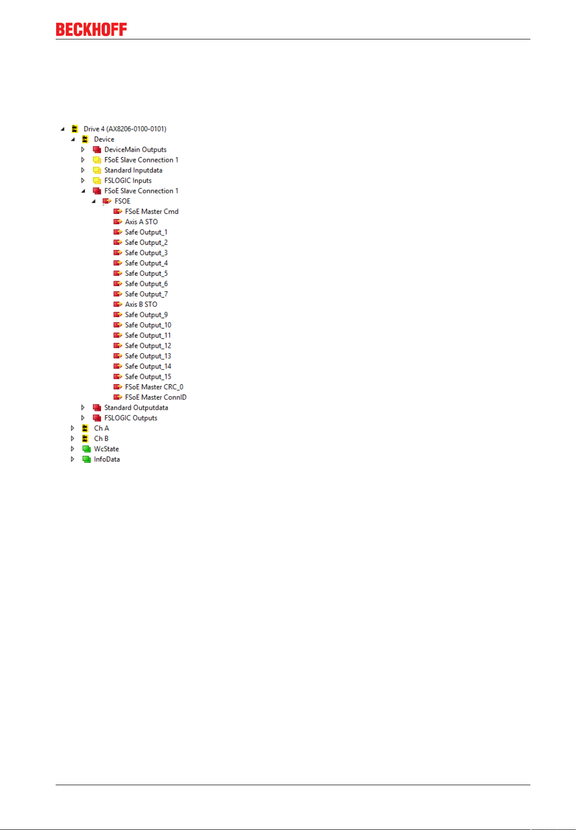
6.1.1 Process image of the AX8xxx-x1xx
The process image of the AX8xxx-x1xx contains process data for the FSoE connection to the internal
AX8911. The telegram length is 7 bytes and thus contains 2 bytes of safe user data. The STO signal for axis
A is located in bit 0 in the first byte. The STO signal for axis B is located in bit 0 in the second byte.
Fig.19: Process image of the AX8206-0100-0101
6.1.2 Error reaction
• Errors in the FSoE slave connection are automatically acknowledged on the slave side (AX8911), since
acknowledgment by the user takes place on the FSoE master side (TwinSAFE logic).
• The rule for all other errors is:
error messages and associated acknowledgments are implemented on the AX8911 TwinSAFE drive
option via the status and control word of the AX8000.
The ErrAck for errors on the AX8911 is implemented via the DS402 control word (bit 7) together with
the reset of the axis via TwinCAT. If an error occurs on the AX8911, a diag message is generated and
the error bit in the DS402 status word (bit 3) is set.
AX8911 - TwinSAFE Drive Option 35Version: 1.0.0
Page 36
Implementation of Safe Motion functions
7 Implementation of Safe Motion functions
7.1 Safe inputs and outputs
At present only the four switch-off channels for STO are usable within the logic. The two outputs for brake
control are not currently used.
7.2 Safety function STO
Refer here to Use of the STO function [}31].
7.3 Safety function SS1
This function is supported by the AX8911 TwinSAFE drive option. In order to use it a user-specific safety
program must be loaded into the AX8911, or the delay of the STO signal must be implemented in the higherlevel safety controller.
7.4 Safety function SS2
This function is not currently supported by the AX8911 TwinSAFE drive option.
7.5 Safety function SOS
This function is not currently supported by the AX8911 TwinSAFE drive option.
7.6 Safety functions SLS, SSM, SSR
These functions are not currently supported by the AX8911 TwinSAFE drive option.
7.7 Safety function SAR
This function is not currently supported by the AX8911 TwinSAFE drive option.
7.8 Safety functions SDIp, SDIn
These functions are not currently supported by the AX8911 TwinSAFE drive option.
7.9 Safety function SLI
This function is not currently supported by the AX8911 TwinSAFE drive option.
7.10 Safety functions SLP, SCA
These functions are not currently supported by the AX8911 TwinSAFE drive option.
AX8911 - TwinSAFE Drive Option36 Version: 1.0.0
Page 37
Diagnostics
A SA S
E
TC
8 Diagnostics
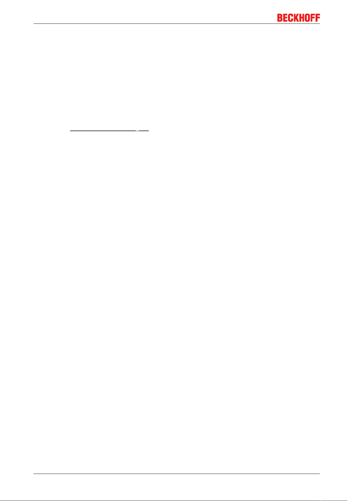
8.1 Diagnostic display of the AX8xxx axis module
Each axis module has an LED display that indicates the present status of each channel. In the case of axis
modules with integrated AX8911 safety option, the present status is displayed with an "S".
Fig.20: AX8xxx axis module display
The following table describes the information provided by the LED "S".
S symbol Meaning
S - off no AX8911 installed
S – steadily lit green Axis enabled
S – flashing green S – steadily lit red STO function active or error
S – flashing red -
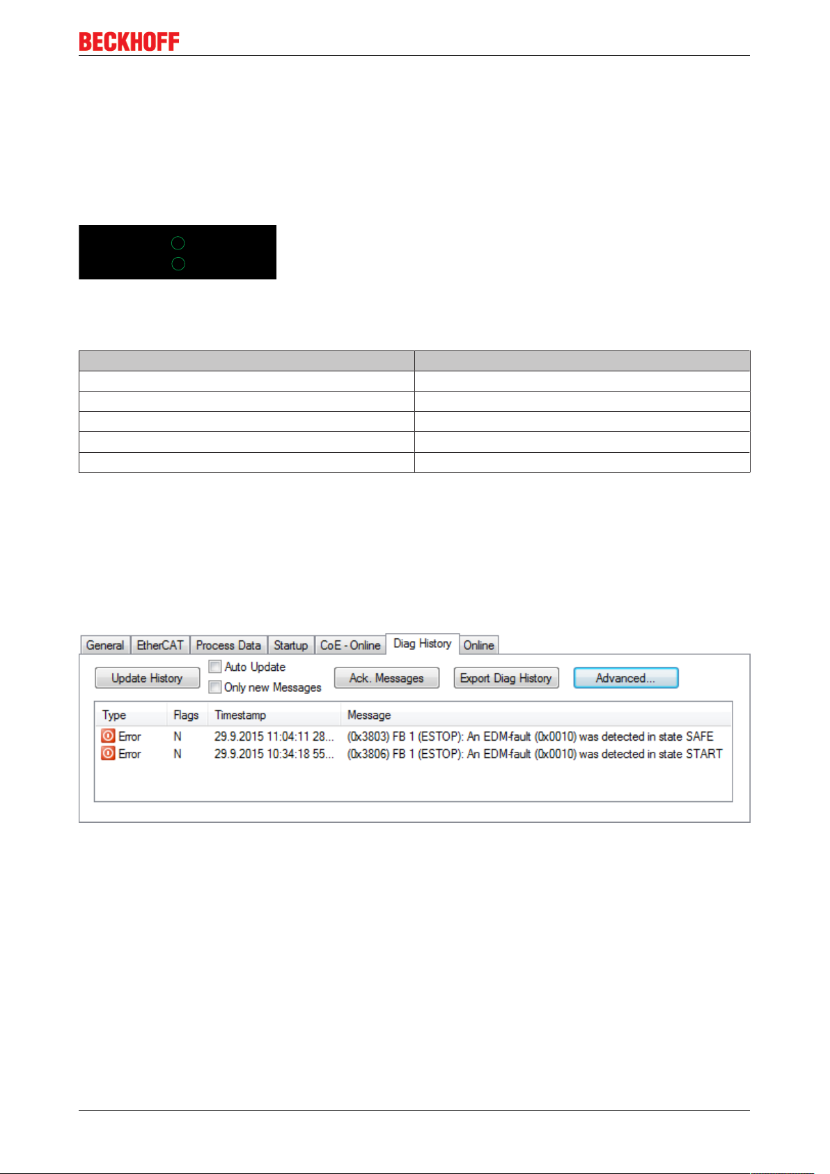
8.2 AX8xxx Diag history tab
Errors in the AX8xxx axis module and the AX8911 TwinSAFE drive option installed in it are stored in the diag
history. The diag history can be viewed by selecting the AX8xxx axis module in the I/O tree structure and
selecting the Diag History tab. The current data can be fetched from the axis module and the TwinSAFE
drive option by actuating the Update History button. All errors that occur are saved with a corresponding
timestamp.
Fig.21: Diag history
Use the Advanced… button to open the advanced settings. Here, the user can customize the behavior of the
diag history.
AX8911 - TwinSAFE Drive Option 37Version: 1.0.0
Page 38
Diagnostics
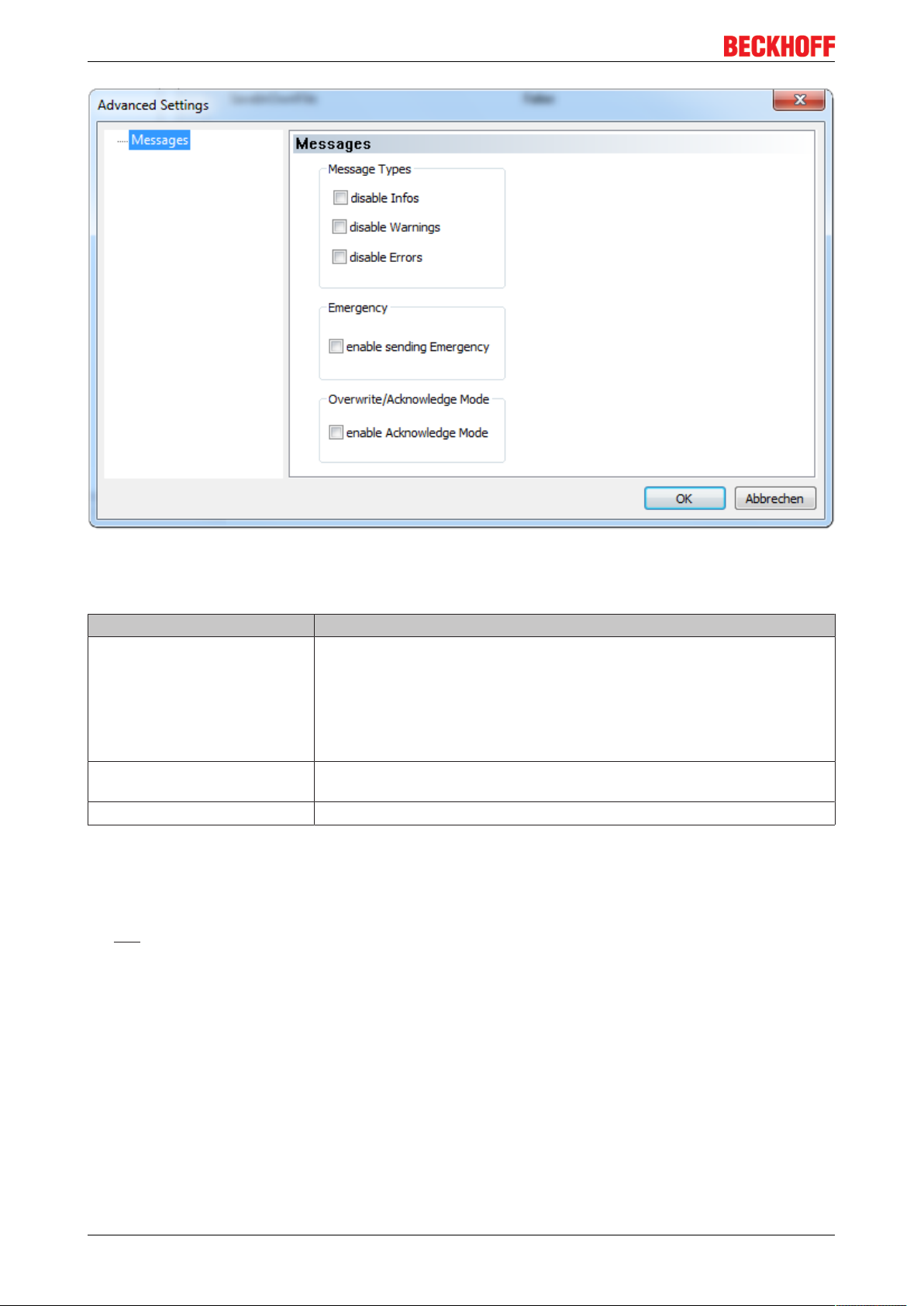
Fig.22: Diag history – advanced settings
Advanced Settings
Setting Description
Message Types • disable Info
Messages with status Info are not stored in the diag history
• disable Warnings
Messages with status Warning are not stored in the diag history
• disable Errors
Messages with status Error are not stored in the diag history
Emergency In addition to saving the message in the diag history, an emergency object
is also sent and displayed in the TwinCAT logger window.
Overwrite / Acknowledge Mode This setting is currently not supported.
8.3 Diagnosis History
The diagnostic history of the TwinSAFE devices that support this function is implemented in accordance with
the ETG guideline ETG.1020 Chapter 13 "Diagnosis Handling". The diagnostic messages are saved by the
TwinSAFE device in a dedicated CoE object under 0x10F3 and can be read out by the application or by
TwinCAT.
Both the control entries and the history itself can be found in the CoE object 0x10F3. The entry Newest
Message (0x10F3:02) contains the subindex of 0x10F3, which contains the latest diagnostic message, e.g.
0x06 for diagnostic message 1.
AX8911 - TwinSAFE Drive Option38 Version: 1.0.0
Page 39

Diagnostics
Index 10F3
Diagnosis History
hex
Index (hex) Name Meaning Data type Flags Default
10F3:0 Diagnosis
History
10F3:01 Maximum
Messages
Maximum number of stored messages. A
maximum of 64 messages can be stored.
UINT8 RO 0x40 (64
After that the respective oldest messages
are overwritten.
10F3:02 Newest
Subindex of the latest message UINT8 RO 0x00 (0
Message
10F3:03 Newest
Subindex of the last confirmed message UINT8 RW 0x00 (0
Acknowledged
Message
10F3:04 New
Indicates that a new message is available BOOLEAN RO 0x00 (0
Messages
Available
10F3:05 Flags Set via the startup list. If set to 0x0001, the
UINT16 RW 0x0000 (0
diagnostic messages are additionally sent
by emergency to the EtherCAT master
10F3:06 Diagnosis
Diagnostic message 1 BYTE[32] RO {0}
Message 001
... ... ... ... ... ...
10F3:45 Diagnosis
Diagnostic message 64 BYTE[32] RO {0}
Message 064
dec
dec
dec
dec
)
)
)
)
)
dec
Structure of the diagnostic messages
• DiagCode (4 bytes) – in this case always 0x 0000 E000
• Flags (2 bytes) - diagnosis type (info, warning or error), timestamp and number of parameters
contained (see the following table)
• Text ID (2 bytes) – ID of the diagnostic message as a reference to the message text from the ESI/XML
• Timestamp (8 bytes) – local slave time in ns since switching on the TwinSAFE device
• dynamic parameters (16 bytes) – parameters that can be inserted in the message text (see following
table)
Flags in diagnostic messages
Data type Offset Description
UINT16 Bits 0 to 3 DiagType (value)
0 Info message
1 Warning message
2 Error message
3…15 reserved
Bit 4 If the bit = 1, the timestamp contained in the message is the local timestamp of the
TwinSAFE device. The age of the diagnostic message can be deduced by
calculation with the current timestamp from the CoE object 0x10F8.
Bits 5 to 7 reserved
Bits 8 to 15 Number of parameters in this diagnostic message
AX8911 - TwinSAFE Drive Option 39Version: 1.0.0
Page 40
Diagnostics
Dynamic parameters in the diagnostic messages
Type Data type Description
Flags parameter 1 UINT16 Describes the type of parameter 1
Bits 12 to 15 =0Bits 0 to 11 = data type of parameter 1
0x0001 - BOOLEAN
0x0002 - INT8
0x0003 - INT16
0x0004 - INT32
0x0005 - UINT8
0x0006 - UINT16
0x0007 - UINT32
0x0008 - REAL32
0x0011 - REAL64
0x0015 - INT64
0x001B - UINT64
Text parameters and formats are
specified in ETG.2000.
Parameter 1 Data type in accordance with
flags
Flags parameter 2 UINT16 see Flags parameter 1
Parameter 2 Data type in accordance with
flags
...
Value of parameter 1
Value of parameter 2
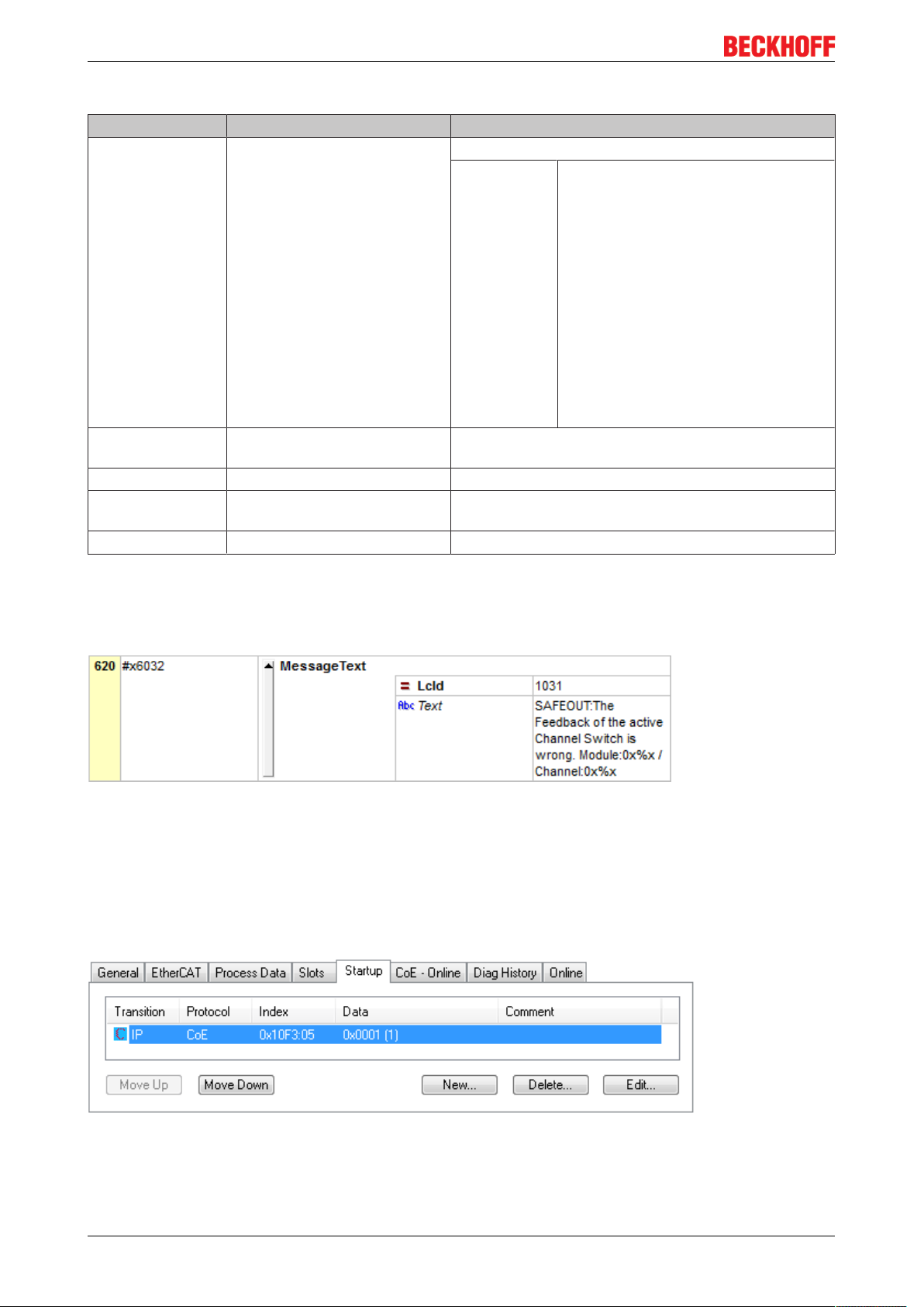
The diagnostic messages are saved in text form in the ESI/XML file belonging to the TwinSAFE device. On
the basis of the Text ID contained in the diagnostic message, the corresponding plain text message can be
found in the respective languages. The parameters can be inserted in the appropriate positions. In the
following example, %x is used for a hexadecimal representation of the parameters.
Fig.23: ESI/XML message text
Via the entry New Messages Available the user receives information that new messages are available. The
messages can be read out via CompleteAccess (a CoE read command for the complete CoE object
0x10F3). The New Messages Available bit is reset after reading the messages.
The sending of emergency messages to the EtherCAT master is activated by adding the CoE object
0x10F3:05 to the startup list (Transition IP, value 0x0001). If new diagnostic messages arrive, they are
entered in object 0x10F3 and additionally sent by emergency to the EtherCAT master.
Fig.24: Startup list
AX8911 - TwinSAFE Drive Option40 Version: 1.0.0
Page 41

Maintenance
9 Maintenance
Maintenance
The TwinSAFE components are maintenance-free!
Environmental conditions
Observe the specified environmental conditions!
Please ensure that the TwinSAFE components are only stored and operated under the
WARNING
If the TwinSAFE component is operated outside the permitted temperature range it will switch to Global
Shutdown state.
Cleaning
Protect the TwinSAFE component from unacceptable soling during operation and storage!
If the TwinSAFE component was subjected to unacceptable soiling it may no longer be operated!
specified conditions (see technical data).
WARNING
Have soiled terminals checked!
Cleaning of the TwinSAFE component by the user is not permitted!
Please send soiled terminals to the manufacturer for inspection and cleaning!
AX8911 - TwinSAFE Drive Option 41Version: 1.0.0
Page 42

Service life
10 Service life
The TwinSAFE drive option has a service life of 20 years.
Due to the high diagnostic coverage within the lifecycle no special proof tests are required.
The internal TwinSAFE drive option has a unique serial number that can be read out over CoE.
The date of manufacture and the serial number of the complete device can be read from the type plate on
the AX8000 axis module. Refer here to the AX8000 startup documentation under References [}8].
Type plate
No. Position No. Position No. Position
1 Order number 6 Rated output current 11 cULus certification
2 Serial number 7 Output frequency range 12 EAC approval
3 Rated input voltage 8 Date of manufacture 13 CE conformity
4 Max. ambient temperature 9 QR code 14 Serial number sticker
5 Rated output voltage 10 EtherCAT conformity 15 Attachment of the type plate
AX8911 - TwinSAFE Drive Option42 Version: 1.0.0
Page 43

Decommissioning
11 Decommissioning
Serious risk of injury!
Bring the AX8xxx into a safe, de-energized state before commencing with the disassembly
DANGER
Disposal
Note
Supplementary information on disposal can be obtained from our Service Dept. (see Support and Service
[}44])
• The device should be disposed of by a certified disposal company. Addresses can be obtained from
our service department.
• Metal parts can be sent for metal recycling.
In accordance with the Directive 2012/19/EU on WEEE we take old devices and accessories back for
professional disposal, provided the transport costs are taken over by the sender. Send the devices with the
note ‘For disposal’ to the Beckhoff headquarters. You can find the address under Support and Service
[}44].
of the devices!
National regulations
Observe the relevant national disposal regulations.
AX8911 - TwinSAFE Drive Option 43Version: 1.0.0
Page 44

Appendix
12 Appendix
12.1 Support and Service
Beckhoff and their partners around the world offer comprehensive support and service, making available fast
and competent assistance with all questions related to Beckhoff products and system solutions.
Beckhoff's branch offices and representatives
Please contact your Beckhoff branch office or representative for local support and service on Beckhoff
products!
The addresses of Beckhoff's branch offices and representatives round the world can be found on her internet
pages:
http://www.beckhoff.com
You will also find further documentation for Beckhoff components there.
Beckhoff Headquarters
Beckhoff Automation GmbH & Co. KG
Huelshorstweg 20
33415 Verl
Germany
Phone: +49(0)5246/963-0
Fax: +49(0)5246/963-198
e-mail: info@beckhoff.com
Beckhoff Support
Support offers you comprehensive technical assistance, helping you not only with the application of
individual Beckhoff products, but also with other, wide-ranging services:
• support
• design, programming and commissioning of complex automation systems
• and extensive training program for Beckhoff system components
Hotline: +49(0)5246/963-157
Fax: +49(0)5246/963-9157
e-mail: support@beckhoff.com
Beckhoff Service
The Beckhoff Service Center supports you in all matters of after-sales service:
• on-site service
• repair service
• spare parts service
• hotline service
Hotline: +49(0)5246/963-460
Fax: +49(0)5246/963-479
e-mail: service@beckhoff.com
AX8911 - TwinSAFE Drive Option44 Version: 1.0.0
Page 45

12.2 Certificates
Appendix
AX8911 - TwinSAFE Drive Option 45Version: 1.0.0
Page 46

Appendix
AX8911 - TwinSAFE Drive Option46 Version: 1.0.0
Page 47

List of figures
List of figures
Fig. 1 AX8911: Connection to X15 and X25.......................................................................................... 18
Fig. 2 Addition of an axis module........................................................................................................... 20
Fig. 3 Addition of an alias device........................................................................................................... 21
Fig. 4 Dialog Add new item AX891x (Safe Drive Module) ..................................................................... 21
Fig. 5 Dialog for linking the variables of the AX8911............................................................................. 22
Fig. 6 Projects with outputs to the AX8911............................................................................................ 23
Fig. 7 Add new item............................................................................................................................... 24
Fig. 8 Target system AX8911 ................................................................................................................ 24
Fig. 9 AX8911 - Add new item .............................................................................................................. 25
Fig. 10 AX8911 - Add new item - Alias Device AX891x .......................................................................... 25
Fig. 11 AX8911 - Linking Mode local ....................................................................................................... 25
Fig. 12 AX8911 – safe inputs of the local alias device ............................................................................ 26
Fig. 13 AX8911 – safe outputs of the local alias device .......................................................................... 28
Fig. 14 TwinSAFE outputs connected to STO inputs .............................................................................. 31
Fig. 15 Safe outputs from a third-party manufacturer connected to STO inputs ..................................... 32
Fig. 16 Safe outputs from a third-party manufacturer connected to STO inputs without the use of test
pulses .......................................................................................................................................... 32
Fig. 17 STO function via TwinSAFE connection...................................................................................... 33
Fig. 18 Default TwinSAFE logic program for AX8911.............................................................................. 34
Fig. 19 Process image of the AX8206-0100-0101................................................................................... 35
Fig. 20 AX8xxx axis module display ........................................................................................................ 37
Fig. 21 Diag history.................................................................................................................................. 37
Fig. 22 Diag history – advanced settings................................................................................................. 38
Fig. 23 ESI/XML message text ................................................................................................................ 40
Fig. 24 Startup list.................................................................................................................................... 40
AX8911 - TwinSAFE Drive Option 47Version: 1.0.0
 Loading...