

Page 1
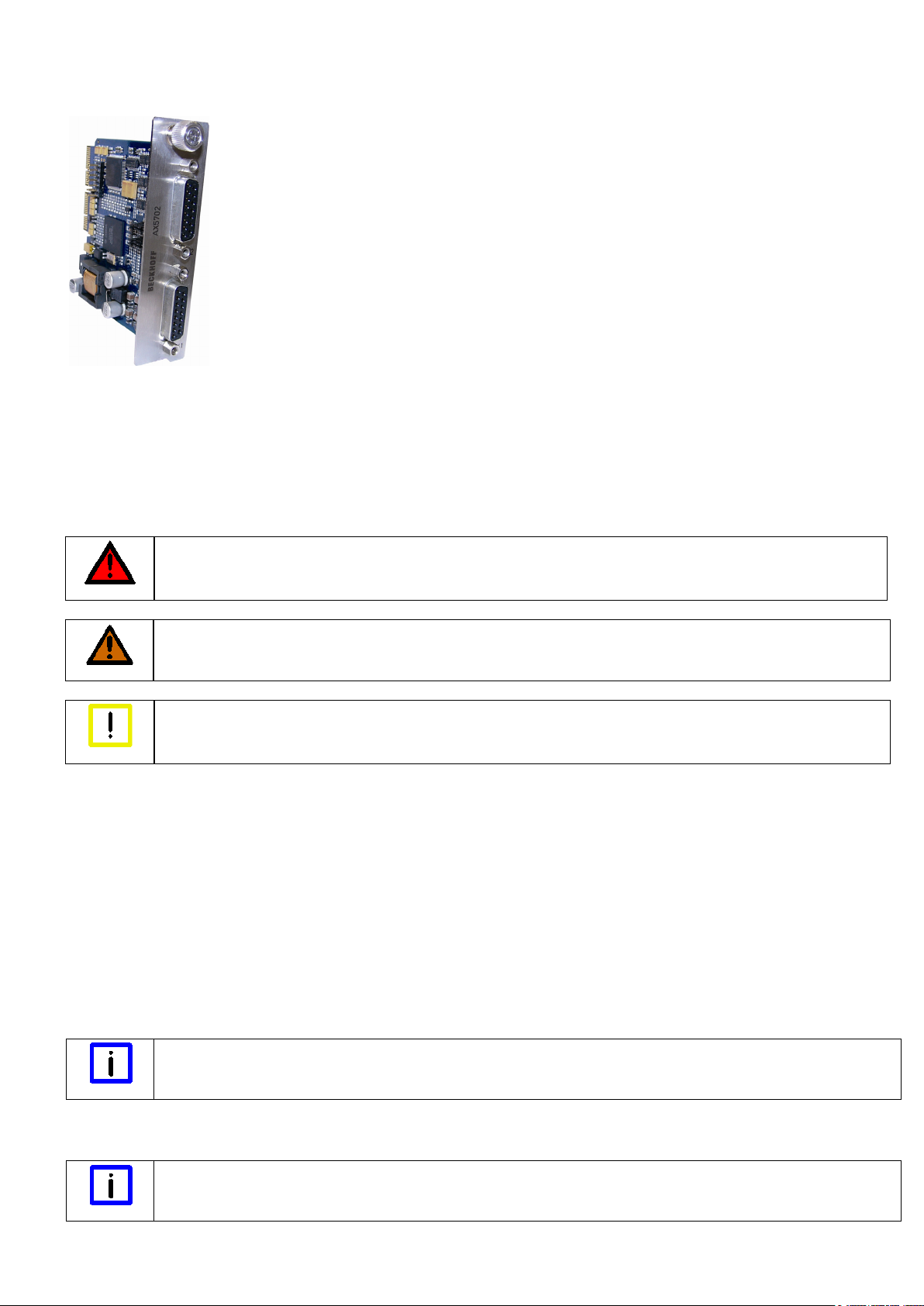
Optional encoder card AX5701 / AX5702
BECKHOFF
DANGER
WARNING
Attention
Note
Note
Drive Technology
Technical Documentation
Eiserstr. 5
Version: 1.7 33415 Verl
Date: 2012-11-16 Germany
Language: EN
Article no.: TDmlAX-570x-0000-0400 Phone: +49(0)5246/963-0
Fax: +49(0)5246/963-198
E-mail Info@beckhoff.com
Internet: www.beckhoff.com
Please read carefully before commissioning!
Beckhoff Automation GmbH
Foreword
Appropriate use
The optional encoder cards are exclusively intended for application in the optional rear slot of a servo drive from the AX5000 series. The cards are
installed together with the servo drive as components in electrical systems and machinery and may only be used in this way.
Security
Safety rules
The responsible staff must ensure that the application or use of the products described satisfy all the requirements for safety, including all the
relevant laws, regulations and guidelines.
Caution – Danger of death!
Even when the AX5000 is disconnected from the mains voltage, dangerous voltage continues to be present at the "X02" terminals
of the DC link for 5 minutes. Never touch the terminals within this period.
Caution – Risk of injury!
Electronic equipment is not fail-safe. The machine manufacturer is responsible for ensuring that the connected motors and the
machine are brought into a safe state in the event of a fault in the drive system.
Destruction of the optional encoder card through electrostatic charging!
The optional encoder card is an ESD-sensitive component. Follow the usual ESD safety procedures when handling the card (antistatic wrist straps, earthing of the relevant components, etc.).
Personnel qualification
This description is only intended for trained specialists in control, automation and drive engineering who are familiar with the applicable national
standards. Knowledge of machine safety legislation is compulsory.
Product description
The optional encoder card enables connection of an additional feedback systems per channel. The system parameters match the standard
parameters that are analysed via inputs X11 and X21. Through simple configuration via jumpers up to six further digital inputs (In “A” to In “F”) can
be analysed, which are provided through special feedback systems via parameter channels. The X41 and X42 sockets are compatible with the
plugs of the X11 and X21 front sockets of the AX5000, which means that the tried and tested cables from the ZK4510 series can be used. To
analyse the additional digital inputs you simply have to insert an adapter or establish a suitable wiring. The optional encoder card cannot be used as
Commutation-Feedbacksystem (primary).
Firmware version
AX5000-xxxx-02xx = mind. FW 2.03 Build 0009
Type key
Operation of the optional encoder card
The AX5701 can only be used in single-channel servo drives, the AX5702 can only be used in two-channel servo drives.
AX5701 – optional encoder card for single-channel servo drives
AX5702 – optional encoder card for two-channel servo drives
Description of the digital inputs
Functional reliability
Ensure that the ground potentials of the digital inputs “A” to “D” are connected with the ground potential of the AX5000.
Inputs “A” to “D” are “single-wire” inputs (single-ended). They have a certain potential to ground, which is analysed.
Inputs “E” and “F” are “two-wire inputs” (differential). They require (+) and (-) and analyse the voltage difference between the conductors.
Page 2
Seite 2/4
Pin
EnDAT / BiSS
Hiperface
Sin / Cos 1Vpp
TTL
In „A“
In „B“
In „C“
In „D“
In „E“
In „F“
1
SIN +
SIN +
SIN +
n.c. X
X (+) 2
GND_5 V
GND_9 V
GND_5 V
GND_5 V
3
COS
COS
COS
n.c. X X (+)
4
US_5 V
n.c.
US_5 V
US_5 V
5
DX+ (Data)
DX+ (Data)
n.c.
B+ Y
6
n.c.
US_9 V
n.c.
n.c. 7 n.c.
n.c.
REF Z
REF Z
8
CLK+ (Clock)
n.c.
n.c.
A+ Y
9
REFSIN
REFSIN
REFSIN
n.c. X
X (-)
10
GND_Sense
n.c.
GND_Sense
GND_Sense
11
REF COS
REF COS
REF COS
n.c. X X (-)
12
US_5 V Sense
n.c.
US_5 V Sense
US_5 V Sense
13
DX- (Data)
DX- (Data)
n.c.
B- Y
14
n.c.
n.c. Z Z
15
CLK- (Clock)
n.c.
n.c.
A- Y
Feedback
Input
Input
Input
Input
Input
Input
EnDAT
Input “A-F” not available
BiSS
Input “A-F” not available
Hiperface
X X
Sin / Cos
TTL
X1
X1
X2
X2
X1
X2
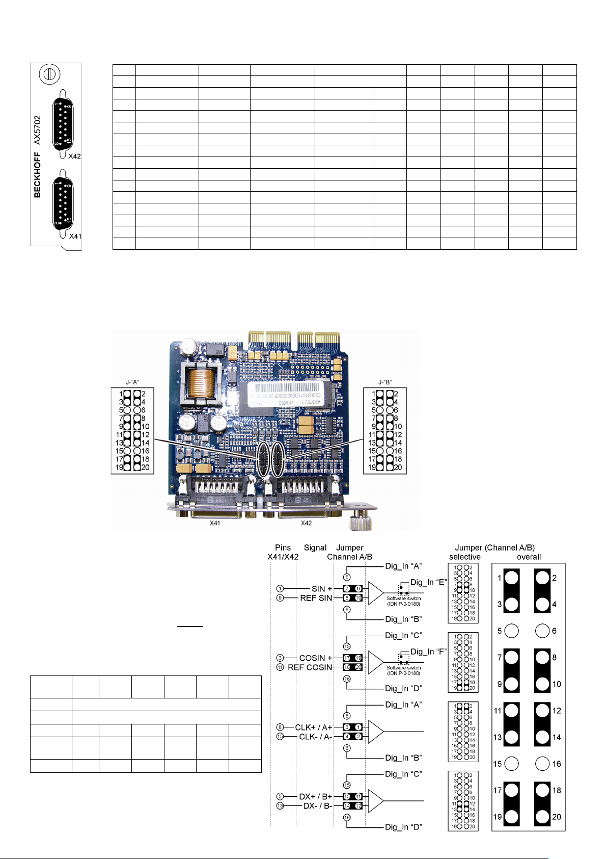
Overview of sockets X41 (channel A) and X42 (channel B)
The digital inputs “A” to “D” can be connected to X or Y.
The digital inputs “E” and “F” must be connected to X (+) and X (-).
Configuration of jumpers J-“A” for channel “A” and J-“B” for channel “B”
Jumpers J-“A” and J-“B” (1) are located at the centre of the printed circuit board near the front panel of the card. For each channel there are 2 row of
jumpers, each with 20 pins. The default setting without analysis of the additional inputs is shown in the following figure.
The opposite figure shows the basic jumper configuration, which
is the same for channel A and channel B. The pins of input
sockets X41 and X42 are wired firmly to the corresponding pins
of the jumpers rows. The non-configurable pins are not shown.
To use the additional inputs proceed as follows:
• Reposition the relevant jumpers und set IDN P-0-
0180Feedback optionsDigital Inputs “Input A” to “Input D”
to “used” or set IDN P-0-0180Feedback optionsDigital
Inputs “Input E” or “Input F” to “used” without repositioning
the jumpers.
• Connect the encoder cable as required for the relevant inputs
or use an adapter.
The following table shows a selection of combination options.
system
1Vpp
1)
Either inputs “A” and “B” or
input “E” can be used.
2)
Either inputs “C” and “D” or
input “F” can be used.
“A”
“B”
X X X X
“C”
“D”
“E”
“F”
Page 3

Technical data
Digital inputs “A” to “D”
Open collector
max. 1
Digital inputs “E” to “F”
0 – 5 V
CAUTION
DANGER
Attention
(single-ended)
Seite 3/4
(differential)
mA
inp. resistance: 120 Ω
Installation of the optional encoder card
Caution – Do not work on live equipment!
Disconnect the equipment at all poles from live parts and secure it against being switched on again, so that there is no possibility of
uncontrolled movements of the equipment occurring.
Caution – Danger of death!
Even when the AX5000 is disconnected from the mains voltage, dangerous voltage continues to be present at the "X02" terminals of
the DC link for 5 minutes. Never touch the terminals within this period.
Destruction of the optional encoder card through electrostatic charging!
The optional encoder card is an ESD-sensitive component. Follow the usual ESD safety procedures when handling the card (antistatic wrist straps, earthing of the relevant components, etc.).
− Fully release the bolt (1).
− Remove the panel (2).
− Carefully insert the optional card (3) into the opening in the direction of
the arrow. The slot has guides for the card on the short sides. Ensure
that the card is inserted into these guides.
− Tighten the bolt (4).
Example: Renishaw RGH 22Z30D00 (TTL encoder with 2 parameter channels)
Configuration via TCDrivemanager (IDN-P-0-0180)
Encoders and inputs
Page 4

Seite 4/4
Pin
Renishaw
In “C”
In “E”
1
Alarm (+)
X (+) 2 GND_5 V
3
Limit switch
X
4
US_5 V
5
B+
6
n.c. 7 REF Z
8
A+ 9 Alarm (-)
X (-)
10
GND_Sense
11
n.c.
12
US_5 V Sense
13
B-
14 Z 15
A-
Jumper configuration
Scaling
Overview of socket X41 (channel A) and jumper configuration
Socket X41
Notes on the documentation
This description is only intended for trained specialists in control, automation and drive engineering who are familiar with the applicable national
standards. It is essential that the following notes and explanations are followed when installing and commissioning these components. The
responsible staff must ensure that the application or use of the products described satisfy all the requirements for safety, including all the relevant
laws, regulations, guidelines and standards.
Disclaimer
The documentation has been prepared with care. The products described are, however, constantly under development. For this reason, the
documentation may not always be have been fully checked for consistency with the performance data, standards or other characteristics described.
In the event that it contains technical or editorial errors, we retain the right to make alterations at any time and without warning. No claims for the
modification of products that have already been supplied may be made on the basis of the data, diagrams and descriptions in this documentation.
Copyright
© Beckhoff Automation GmbH
The reproduction, distribution and utilization of this document as well as the communication of its contents to others without express authorization
are prohibited.
Offenders will be held liable for the payment of damages. All rights reserved in the event of the grant of a patent, utility model or design.
Scope of supply
The scope of supply includes the following components:
Optional encoder card AX570x, technical documentation and packaging
If one of the components is damaged please notify the logistics company and Beckhoff Automation GmbH immediately.
 Loading...