

Page 1
Documentation
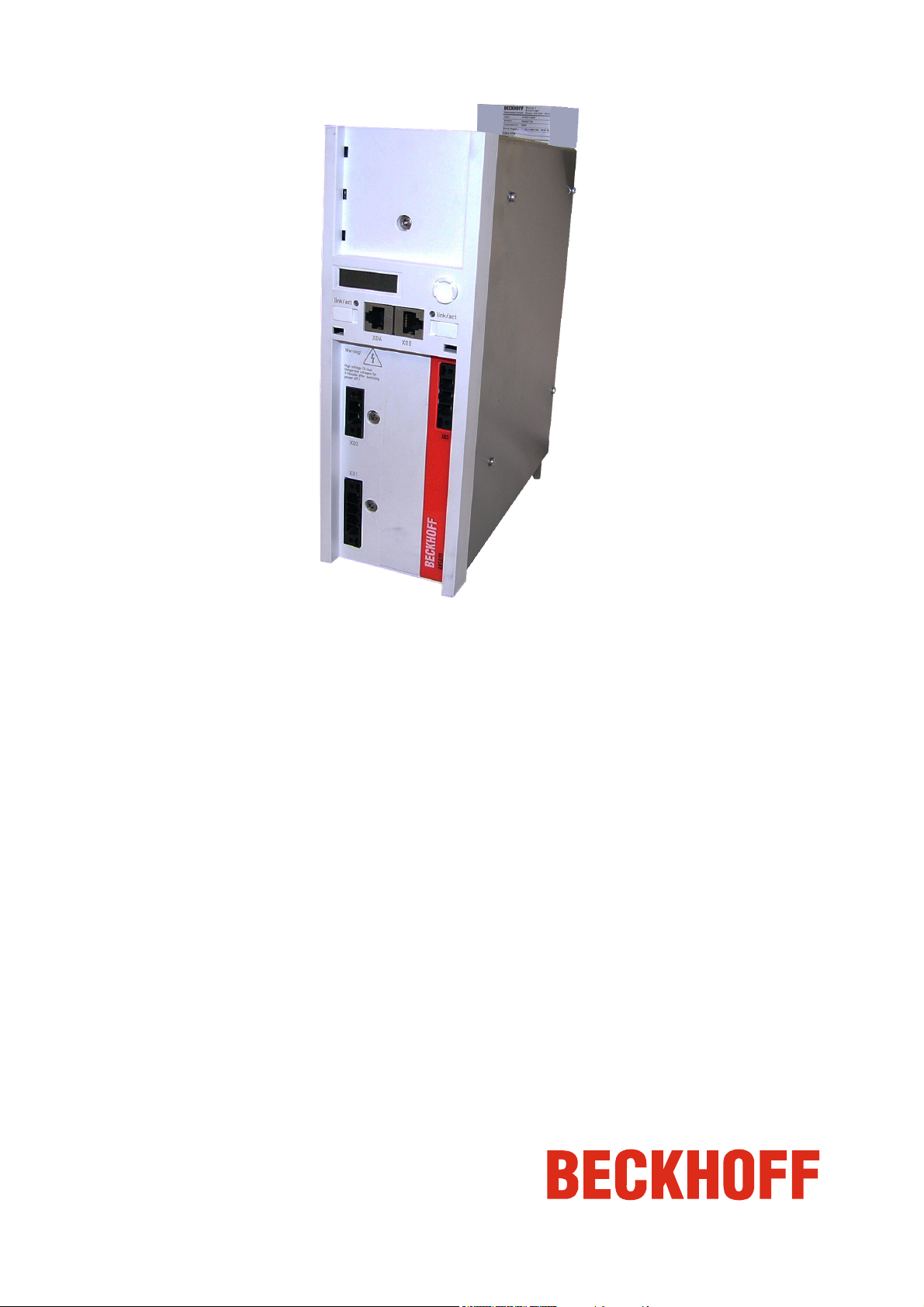
Brake module AX5021
Please read this document carefully before installing and commissioning the brake module!
Version : 1.2
Date
Article-no. : TDmlAX-5021-0000-0200
: 2012.03.05
Page 2

Page 2/8 Brake module AX5021 – Version: 1.2 BECKHOFF Drive Technology
Notes on the documentation
Documentation issue status
Version Comment
1.2 New chapter
1.1 Not published
1.0 First edition
Copyright
© Beckhoff Automation GmbH
The reproduction, distribution and utilization of this document as well as the communication of its contents to others without express authorization
are prohibited.
Offenders will be held liable for the payment of damages. All rights reserved in the event of the grant of a patent, utility model or design.
Trademarks
Beckhoff®, TwinCAT®, EtherCAT®, Safety over EtherCAT®, TwinSAFE® and XFC® are registered trademarks of and licensed by Beckhoff
Automation GmbH.
Other designations used in this publication may be trademarks whose use by third parties for their own purposes could violate the rights of the
owners
Patent Pending
The EtherCAT Technology is covered, including but not limited to the following patent applications and patents:
EP1590927, EP1789857, DE102004044764, DE102007017835
with corresponding applications or registrations in various other countries
The TwinCAT Technology is covered, including but not limited to the following patent applications and patents:
EP0851348, US6167425 with corresponding applications or registrations in various other countries.
Braking power diagnosis
Chapter update
Safety regulations; Product description; Electrical data; General overview; Electrical connection; Configuration in the
TCDriveManager; Operating modes of the AX5021
Page 3
BECKHOFF Drive Technology Brake module AX5021 – Version: 1.2 Page 3/8
Foreword
Disclaimer
The responsible staff must ensure that the application or use of the products described satisfy all the requirements for safety, including all the
relevant national laws, regulations and guidelines.
All the components are supplied in particular hardware and software configurations appropriate for the application. Modifications to hardware or
software configurations other than those described in the documentation are not permitted, and nullify the liability of Beckhoff Automation GmbH.
The documentation has been prepared with care. The products described are, however, constantly under development.
For that reason the documentation is not in every case checked for consistency with performance data, standards or other characteristics.
In the event that it contains technical or editorial errors, we retain the right to make alterations at any time and without warning.
No claims for the modification of products that have already been supplied may be made on the basis of the data, diagrams and descriptions in this
documentation.
Appropriate use
The AX5021 brake module is intended exclusively for direct use in a drive system with servo drives from the AX5000 series. The brake modules are
installed together with the servo drives as components in electrical systems and machinery and may only be used in this way.
Scope of supply
The scope of supply includes the following components:
brake module, technical documentation and packaging
If one of the components is damaged please notify the logistics company and Beckhoff Automation GmbH immediately.
Safety
Safety regulations
The responsible staff must ensure that the application or use of the products described satisfy all the requirements for safety, including all the
relevant laws, regulations and guidelines.
Caution – Danger of death!
Due to the DC link capacitors dangerous voltage may persist at the DC link contacts "X02" after the servo drive has been
disconnected from the mains supply. After disconnecting the servo drive wait 5 minutes and measure the voltage at the DC link
DANGER
WARNING
contacts DC+ and DC-. The device is safe once the voltage has fallen below 50 V.
Caution - Risk of injury through hot surfaces!
The surface of the brake module housing can become very hot. Please ensure that the housing has cooled down below 40 °C before
touching it.
Personnel qualification
This description is only intended for trained specialists in control, automation and drive engineering who are familiar with the applicable national
standards. Knowledge of machine safety legislation is compulsory.
Product description
Using a brake module it is possible to take up additional braking power in a drive system, because the connection of an external brake resistor
without a brake module in a drive system with devices up to max. 25 A rated current is not permissible. A further advantage is the simple installation
and the small space requirement of the brake module. The brake module is equipped with a complete DC link and an internal brake resistor and
enables the connection of an external brake resistor with the integrated brake chopper. Several brake modules can be integrated into a drive
system.
Operating conditions!
The brake module may only be used together with servo drives of the AX51xx-xxxx-02xx or AX52xx-xxxx-02xx series. These
Note
Electrical data
Internal resistance
Continuous braking power
P
rms
[W]
150 14.000 22 6.000 max. 32,000
devices have serial numbers above 100.000.
In addition to the AX5021, the drive system must include at least 2 further servo drives from the AX5000 range.
Internal resistance
Peak braking power P
[W]
External resistance min.
peak
[Ω]
External resistance
Continuous braking power
P
rms
[W]
External resistance
Peak braking power P
[W]
peak
Page 4

Page 4/8 Brake module AX5021 – Version: 1.2 BECKHOFF Drive Technology
Mechanical data
The external dimensions of the brake module are identical to the dimensions of the servo drives from the AX5000 series up to 12 A.
Mechanical data AX5021
Weight approx. 4 kg
Width 92 mm
Height without plugs 274 mm
Depth without connectors / accessories 232 mm
General overview
No Designation
1 Navigation rocker
2 Labelling field
3 X05 - socket for EtherCAT output
4 X03 - power supply 24 V DC input
5 X52 - connection of the temperature monitor and the fan of the external brake resistor
6 X51 - connection of the external brake resistor
7 X01 - mains supply 100 - 480 V
8 X02 - DC link output
(890 V DC voltage)
9
DANGER
10 X04 - socket for EtherCAT input
11 Display
890 V DC voltage at the DC link terminals. Dangerous voltage may
be present for 5 minutes after the device is switched off. The device
is safe once the voltage has fallen below 50 V.
Page 5

BECKHOFF Drive Technology Brake module AX5021 – Version: 1.2 Page 5/8
Pin strip assignment of X51 and X52
No Designation
1 T- = input of the temperature measurement sensor of the external brake
resistor
2 T+ = input of the temperature measurement sensor of the external brake
resistor
3 PE = protective conductor
4 F- = output to the fan controller of the external brake resistor
5 F+ = output to the fan controller of the external brake resistor
6 PE = protective conductor
7 B- = output to the controller of the external brake resistor
8 B+ = output to the controller of the external brake resistor
Please refer to the servo drive ‘Startup’ manual for the pin assignments of the remaining inputs and outputs.
Temperature rise in an external brake resistor
The temperature rise of the external brake resistor should be monitored continuously via temperature contacts (1) and (2).
Note
Electrical connection (example)
Caution – Danger of death!
Even when the AX5021 is disconnected from the mains voltage, dangerous voltage continues to be present at the "X02" terminals
DANGER
The example below describes the brake module and several servo drives, which are linked via AX-Bridge modules to make up a drive system. We
recommend that the brake module be placed in the first position with the AX-Bridge power supply module (AX5901) and after that the servo drives
with decreasing rated current; we assume here that the most powerful servo drive also releases the greatest brake energy.
Caution
Due to the characteristic of the brake module, a mains failure is recognised immediately; hence, it is necessary that you monitor the ready status of
the brake module and disconnect the entire drive system from the mains if necessary. Cyclically check bit 4 – ‘ext. Umain relay’ – in the ‘power
management status word’ (IDN P-0-0205) in the controller. If its value is ‘0’, you must ensure that the mains contactor (9) trips, thus disconnecting
the complete drive system from the mains. For this, you can use a separate output terminal (2) or a free output ‘8’ of the digital I/O s (2A) of a servo
drive.
Caution
of the DC link for 5 minutes. Never touch the terminals within this period.
Hazard to devices
Please analyse your application. The brake module should always be placed directly beside the servo drive that releases the
greatest brake energy. This rule should also be applied if several brake modules are used in a drive system.
Pos. Designation
1 PC with TwinCAT and PLC
2 Output terminal
2A Output ‘8’ of the servo drive digital I/Os
3 Brake module
4 Servo drive (with the greatest brake energy)
5 Servo drive
6 Patch cable
7 Control cable from the output terminal
7A Control cable from output ‘8’ of the servo drive digital I/Os
8 Mains fuses
9 Mains contactor
Uncontrolled movements
If the drive system is disconnected from the mains due to a mains failure, all axes of the drive system make uncontrolled
movements. Take suitable measures to ensure than no persons are endangered during this time. Vertical axes are particularly
dangerous.
Page 6

Page 6/8 Brake module AX5021 – Version: 1.2 BECKHOFF Drive Technology
Integration into TwinCAT
The brake module can be integrated in the TwinCAT System Manager as a completely normal I/O device (1) and is parameterised (3) with the
TCDrive Manager (2).
Configuration in the TCDriveManager
Power Management
Pos. Designation Pos. Designation
1 Power management 6 Activation / deactivation of the internal brake resistor
2 Mains voltage selection 7 External brake resistor parameter list
3 Phase monitoring (deactivate for single-phase mains) 8 0 = Deactivation of the external brake resistor
4 Delay time until the phase monitoring responds (activate if mains is
unclean)
5 Internal brake resistor parameter list
9 Enabling / disabling the fan of the external brake resistor and
(not recommended)
1 = Standard energy management with external
brake resistor
2 = Energy management with external brake resistor
(standalone)
setting the switching thresholds.
Switch on Level: Percentage specification of the rated capacity
value of the external brake resistor.
Switch on Temp.: Max. temperature value of the external brake
resistor in °C.
Page 7

BECKHOFF Drive Technology Brake module AX5021 – Version: 1.2 Page 7/8
Energy management
Intelligent energy management ensures that energy is distributed evenly to the DC links and the internal brake resistors when devices are used
commonly in the drive system. This reliably prevents the undesirable permanent load of only one device.
DC link
The connected servomotors are supplied with energy from the DC link. It serves as an energy storage and first needs to be charged up after
switching the device on, before it can supply the servomotors. The DC link is designed such that it can take up and store a certain degree of surplus
energy from the motor (brake energy) and subsequently supply the motor again with this stored energy. If the upper limit of the energy storage is
reached, the brake chopper feeds any further brake energy into the internal or external brake resistor, where it is converted into heat; it is then no
longer available for the further operation of the motor. The voltage is taken and evaluated as the indicator for the current energy level of the DC link.
As soon as the brake resistors have also reached their energy limit, the error ‘FD4C, DC link – overvoltage’ appears and the energy flow to and from
the motor is interrupted, i.e. the motor makes uncontrolled movements.
In a drive system, the DC links of the individual devices are connected so that the energy level of all devices is the same, regardless of which motor
the brake energy is currently being fed back from. In many cases these feedbacks do not happen at the same time, and without a DC link system,
for example, a device would be at the limit and would already have to ‘destroy’ energy in a brake resistor, even though other devices could still store
energy in the DC link. The energy could be saved in a DC link system, because the DC links of all connected devices are charged up first, before
the energy is converted into heat in the brake resistors.
Operating modes of the AX5021
It can be assumed that a brake module is used only if the brake energy cannot be dissipated despite a DC link system and internal brake resistors.
The brake module can be operated in 2 different operating modes, which have a direct influence on the energy management. The operating modes
can be selected when using the external brake resistor. The following sketches show the storage capacity of the DC link of the individual devices in
relation to the operating modes.
Standard operating mode 1 Ext. brake resistor enabled (system / standard)
Operating mode 2 Ext. brake resistor enabled (standalone brake chopper)
Braking power diagnosis
The current continuous output of the brake resistor can be read via the IDNs P-0-0209 (int. brake resistor) and P-0-0210 (ext. brake resistor). The
unit is watts. Loads above 90% of the continuous output of the brake resistor should be avoided. The IDNs can be read cyclically as process data.
The current impulse energy load of the brake resistor can be read via the IDNs P-0-0218 (int. brake resistor) and P-0-0219 (ext. brake resistor). It is
specified in % with one decimal place. Loads above 90% should be avoided. The IDNs can be read cyclically as process data.
The maximum energy values since the last reset are stored in IDNs P-0-0220 (int. brake resistor) and P-0-0221 (ext. brake resistor). The values can
be reset by entering zero. Duty cycle corresponds to 100 seconds. The energy values are monitored at the specified intervals (100 ms, 1 s, 10 s, 20
s, 40 s and 100 s). The values for 100 s correspond to the continuous output. The maximum values should be approx. 10% below the resistor limits
(P-0-0207 or P-0-0208). If a current energy value exceeds the limit value of a brake resistor, this brake resistor is not enabled. In a drive systems or
in a configuration with active internal chopper the other brake resistors have to absorb the energy. If this is not possible the DC link voltage will
continue to increase until an overvoltage error occurs, followed by disabling of the axes with "Torque off". It is therefore important to ensure that
adequate braking power is available in the systems, in order to avoid uncontrolled movements of the axes. The diagnostics should cover the whole
system. If not enough reserve capacity is available, an external brake resistor with a higher output should be selected. If the performance limit is still
reached, several AX5021 may be used.
Note
In this operating
At 90% DC link load the brake chopper then directs the generated braking energy to the external
brake resistor and, when this has reached its capacity limit, into the internal brake resistor.
This operating mode is set as the default, because no further configuration of the devices in the DC
link system is necessary apart from the basic configuration of the brake module. If the external
brake resistor of the brake module is mounted outside the control cabinet, then the thermal load in
the control cabinet is also lower.
In this case the c
servo drives should be deactivated, so that the surplus energy is only taken up by the brake
module.
This operating mode must be selected and, apart from the basic configuration of the brake module,
the internal brake resistors of the devices in the DC link system should be deactivated, as otherwise
the thermal load in the control cabinet will also increase. In order to reduce the thermal load further,
it is a good idea to mount an external brake resistor on the brake module outside the control
cabinet.
mode the capacity of the DC link of the brake module is reduced by approx. 10%.
apacity of the DC links is fully utilised; however, the internal brake resistors of the
Energy balance!
The energy balance is affected positively whenever an axis requires energy and another axis produces generative energy
(braking energy). This rule should be observed in all applications.
Page 8

Page 8/8 Brake module AX5021 – Version: 1.2 BECKHOFF Drive Technology
Appendix
Support and Service
Beckhoff and their partners around the world offer comprehensive support and service, making available fast and competent assistance with all
questions related to Beckhoff products and system solutions.
Beckhoff's branch offices and representatives
Please contact your Beckhoff bra
The addresses of Beckhoff's branch offices and representatives round the world can be found on her internet pages:
www.beckhoff.com
You will also find further documentation
nch office or representative for local support and service
for Beckhoff components there.
Beckhoff headquarters
Beckhoff Automation GmbH
Eiserstr. 5
33415 Verl
Germany
Phone: +49(0)5246/963-0
Fax: +49(0)5246/963-198
e-mail: info@beckhoff.com
Beckhoff Support
Beckhoff offers comprehensive te
additional services:
chnical support that deals not only with the application of individual Beckhoff products, but offers extensive
• support
• design, programming and commissioning of complex automation systems
• extensive training program for Beckhoff system components
Hotline : +49(0)5246/963-157
Fax : +49(0)5246/963-9157
e-mail : support@beckhoff.com
Beckhoff Service
The Beckhoff Se
rvice Center supports you in all matters of after-sales service:
• local service
• repair service
• spare parts service
Hotline : +49(0)5246/963-460
Fax : +49(0)5246/963-479
e-mail: : service@beckhoff.com
The addresses of the worldwide Beckhoff branch offices and representatives can be found on our website at www.beckhoff.com
further documentation
for Beckhoff components there.
on Beckhoff products!
You will also find
 Loading...