

Page 1
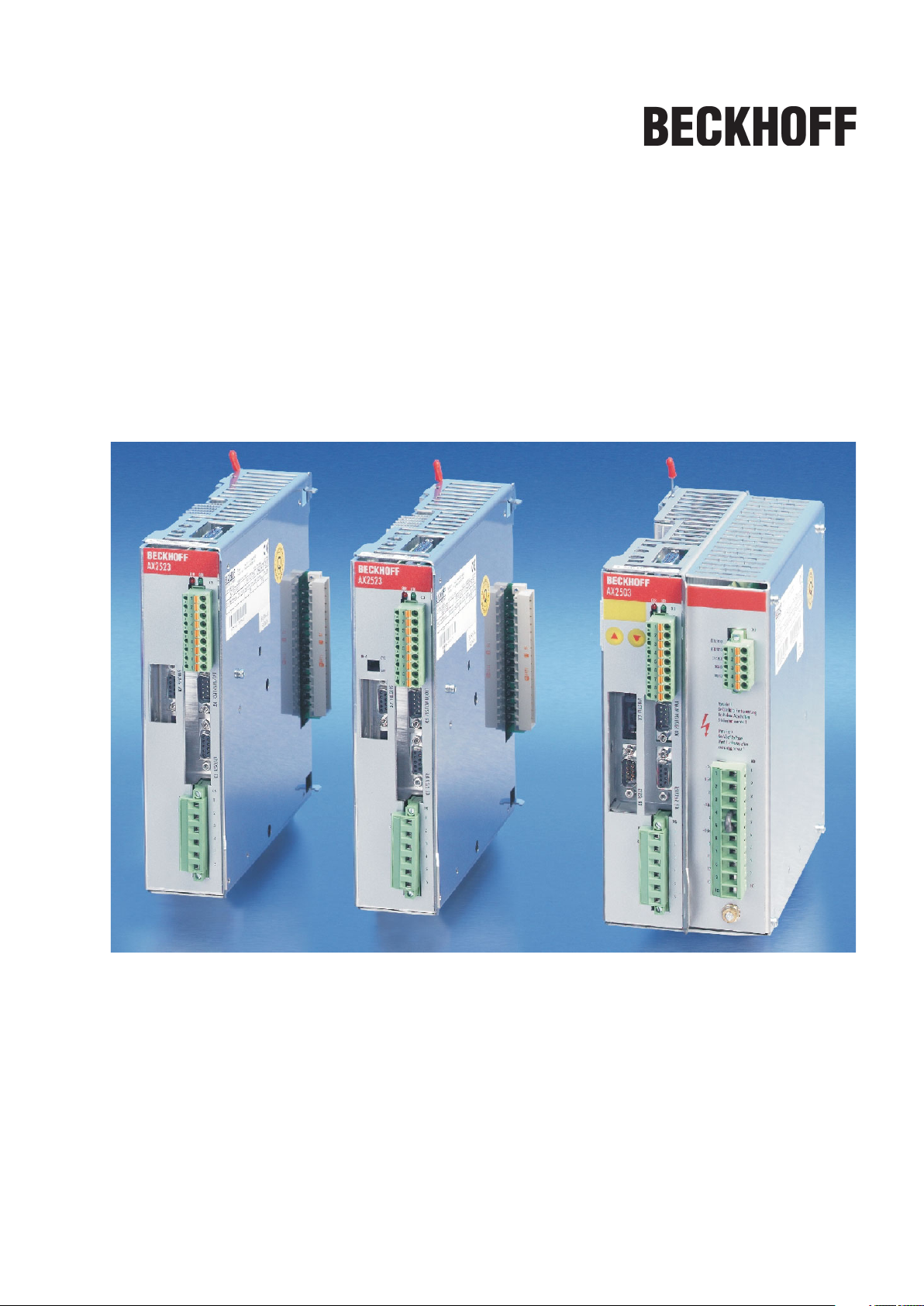
Digital Servo Amplifier
AX2500
Assembly, Installation, Setup
Keep all product manuals as a product component
during the life span of the servo amplifier.
Pass all product manuals to future
users / owners of the servo amplifier.
Edition 06/2007
Page 2

Previous editions
Edition Comments
07/03 First edition
07/05
SSI emulation updated (Multiturn), UL/cUL information updated,
typographical changes, chapter 1 new sorted, several corrections
02/06 Chapter feedback updated, label updated, several small corrections
PROFIBUS Topologie, part number scheme, trouble-shooting reduced, "Components of a servo
system" extended and moved, disposal acc. to WEEE-2002/96/EG, new document structure,
06/07
Quickstart integrated, EtherCat type new, 24V supply voltage hints, feedback expanded,
BISS-Interface, Stop/Emergency-Stop expanded, shock-hazard protection new, DC-Bus link ex
panded, accessories removed, timing diagramm motor brake
-
WINDOWS is a registered trademark of Microsoft Corp.
HIPERFACE is a registered trademark of Max Stegmann GmbH
EnDat is a registered trademark of Dr.Johannes Heidenhain GmbH
Technical changes to improve the performance of the equipment may be made without notice !
Printed in the Federal Republic of Germany
All rights reserved. No part of this work may be reproduced in any form (by printing, photocopying, microfilm
or any other method) or processed, copied or distributed by electronic means without the written permission
of BECKHOFF.
Page 3

BECKHOFF 06/2007 Contents
page
1 General
1.1 About this manual................................................................7
1.2 Hints for the online edition (PDF format) ..............................................7
1.3 Symbols used ...................................................................7
1.4 Abbreviations used ...............................................................8
2 Safety
2.1 Safety Instructions ...............................................................9
2.2 Use as directed.................................................................10
3 Standards
3.1 European Directives and Standards.................................................11
3.2 American Directives and Standards .................................................11
3.3 Asian Directives and Standards ....................................................11
3.4 Approvals .....................................................................12
3.4.1 CE conformance ...........................................................12
3.4.2 UL and cUL- Conformance ...................................................12
4 Handling
4.1 Transport .....................................................................13
4.2 Packaging .....................................................................13
4.3 Storage .......................................................................13
4.4 Maintenance / Cleaning ..........................................................13
4.5 Disposal ......................................................................13
5 Package
5.1 Package supplied ...............................................................14
5.2 Nameplate ....................................................................14
5.3 Part number scheme ............................................................15
6 Technical description
6.1 Digital servo amplifiers in the series AX2500 ..........................................16
6.2 Technical data .................................................................18
6.2.1 Rated data ................................................................18
6.2.2 Inputs / Outputs ............................................................19
6.2.3 Recommended tightening torques .............................................19
6.2.4 Fusing ...................................................................19
6.2.5 Ambient conditions, ventilation, mounting position .................................20
6.2.6 Conductor cross-sections ....................................................20
6.3 LED display....................................................................20
6.4 Control for motor holding brake ....................................................21
6.5 Grounding system ..............................................................22
6.6 Regen circuit...................................................................22
6.7 Switch-on/-off behavior...........................................................23
6.7.1 Behavior in standard operation ................................................24
6.7.2 Behavior in the event of an error (with standard setting) ............................25
6.8 Stop / Emergency Stop Function to EN 60204.........................................26
6.8.1 Stop: Standards............................................................26
6.8.2 Emergency Stop: Standards ..................................................27
6.8.3 Implementation of the Stop Category 0..........................................28
6.8.4 Implementation of the Stop Category 1..........................................29
6.8.5 Implementation of the Stop Category 2..........................................30
6.9 Shock-hazard protection..........................................................31
6.9.1 Leakage current ...........................................................31
6.9.2 Residual-current circuit breakers (FI) ...........................................31
6.9.3 Isolating transformers .......................................................32
AX2500 Product Manual 3
Page 4

Contents 06/2007 BECKHOFF
page
7 Mechanical Installation
7.1 Important notes.................................................................33
7.2 Guide to mechanical installation....................................................33
7.3 Mounting ......................................................................34
7.4 Dimensions ....................................................................35
7.5 Add-on fan ....................................................................36
8 Electrical Installation
8.1 Important notes.................................................................37
8.2 Guide to electrical installation......................................................38
8.3 Wiring ........................................................................39
8.3.1 Important notes ............................................................39
8.3.2 Shield connection on the front panel............................................40
8.3.3 Requirements to cables......................................................41
8.4 Components of a servo system ....................................................42
8.5 Block diagram ..................................................................43
8.6 Connector assignments ..........................................................44
8.7 Connection diagram AX250x and AX251x (overview) ...................................45
8.8 Connection diagram AX252x (overview) .............................................46
8.9 Power supply, master only ........................................................47
8.9.1 Mains supply connection (X0) .................................................47
8.9.2 24V auxiliary voltage (X0) ....................................................47
8.10 DC Bus link (X0) ................................................................48
8.11 Motor connection with brake (X6)...................................................48
8.12 External regen resistor (X0), master only.............................................48
8.13 Feedback .....................................................................49
8.13.1 Resolver (X5) .............................................................50
8.13.2 Sine encoder 5V with BISS (X2) ...............................................51
8.13.3 Sine Encoder with EnDat 2.1 or HIPERFACE (X2) ................................52
8.13.4 Sine Encoder without data channel (X2).........................................53
8.13.5 Incremental or sine encoder with hall sensors (X2) ................................54
8.13.6 Incremental Encoder (X4) ....................................................55
8.14 Electronic Gearing, Master-slave operation ...........................................56
8.14.1 Connection to a AX2500 master, 5 V signal level (X4) .............................57
8.14.2 Connection to incremental encoder master with 24 V signal level (X3) ................57
8.14.3 Connection to a sine-cosine encoder master (X2).................................58
8.14.4 Connection to a SSI encoder (X4) .............................................59
8.14.5 Connection to stepper motor controllers (pulse and direction) ........................59
8.14.5.1 Step/Direction with 5 V signal level (X4) ......................................60
8.14.5.2 Step/Direction with 24 V signal level (X3) .....................................60
8.15 Encoder emulations .............................................................61
8.15.1 Incremental encoder output - A quad B (X4) .....................................61
8.15.2 SSI output (X4) ............................................................62
8.16 Digital and analog inputs and outputs ...............................................63
8.16.1 Analog input (X3)...........................................................63
8.16.2 Digital inputs (X3) ..........................................................64
8.16.3 Digital outputs (X3) .........................................................65
8.16.4 Digital I/O on the Master (X1) .................................................66
8.17 RS232 interface, PC connection (X8), master only.....................................67
8.18 Fieldbus connection .............................................................68
8.18.1 CANopen interface (X7) .....................................................68
8.18.2 PROFIBUS interface (X7), option ..............................................69
8.18.3 SERCOS interface (X7), option................................................70
8.18.3.1 Light emitting diodes (LEDs) ...............................................70
8.18.3.2 Connection diagram .....................................................70
8.18.4 EtherCat interface (X7), option ................................................71
8.18.4.1 EtherCat connection, connector X7A/B (RJ-45) ................................71
8.18.4.2 Connection diagram .....................................................71
4 AX2500Product Manual
Page 5

BECKHOFF 06/2007 Contents
page
9Setup
9.1 Important notes.................................................................73
9.2 Setup software .................................................................74
9.2.1 General ..................................................................74
9.2.1.1 Use as directed .........................................................74
9.2.1.2 Software description .....................................................74
9.2.1.3 Hardware requirements...................................................75
9.2.1.4 Operating systems ......................................................75
9.2.2 Installation under WINDOWS 98 / 2000 / ME / NT / XP .............................75
9.3 Quickstart, drive test.............................................................76
9.3.1 Preparation ...............................................................76
9.3.1.1 Unpacking, Mounting and Wiring the Servo Amplifier ...........................76
9.3.1.2 Documents ............................................................76
9.3.1.3 Minimum Wiring for Drive Test .............................................77
9.3.2 Connect ..................................................................78
9.3.3 Important Screen Elements...................................................79
9.3.4 Basic Setup ...............................................................80
9.3.5 Motor (synchronous) ........................................................81
9.3.6 Feedback.................................................................82
9.3.7 Save Parameters and Restart.................................................83
9.3.8 Jogging the Motor (Speed Control) .............................................84
9.3.9 Status ...................................................................85
9.3.10 Monitor...................................................................85
9.3.11 Additional Setup Parameters..................................................85
9.4 Multi-axis systems ..............................................................86
9.4.1 Station Address ............................................................86
9.4.2 Example of connections for multi-axis system ....................................87
9.5 Key pad controls and status displays ................................................88
9.5.1 Operating.................................................................88
9.5.2 Status display on the axis module..............................................88
9.5.3 Status display on the master..................................................89
9.6 Error messages ................................................................90
9.7 Warning messages..............................................................91
9.8 Trouble Shooting ...............................................................92
10 Appendix
10.1 Glossary ......................................................................93
10.2 Index .........................................................................95
AX2500 Product Manual 5
Page 6

06/2007 BECKHOFF
This page has been deliberately left blank.
6 AX2500 Product Manual
Page 7
BECKHOFF 06/2007 General
1 General
1.1 About this manual
This manual describes the digital servo amplifiers of the AX2500 series.
A more detailed description of the field bus interfaces and the digital connection to auto
mation systems can be found on the accompanying CD-ROM in PDF format (system
requirements: WINDOWS, Internet browser, Acrobat Reader) in several language ver
sions.
You can print out this documentation on any standard printer. A printed copy of the docu
mentation is available from us at extra cost.
This manual makes the following demands on qualified personnel :
Transport: only by personnel with knowledge of handling
electrostatically sensitive components.
Unpacking: only by electrically qualified personnel.
Installation: only by electrically qualified personnel.
Setup: only by qualified personnel with extensive knowledge of
electrical engineering / drive technology.
1.2 Hints for the online edition (PDF format)
Bookmark:
Table of contents and index are active bookmarks.
Table of contents and index in the text:
The lines are active cross references. Click on the desired line and the appropriate page
is indicated.
-
-
-
Page/chapter numbers in the text:
Page/chapter numbers with cross references are active. Click at the page/chapter number to reach the indicated target.
1.3 Symbols used
Danger to personnel
from electricity and its
effects effects
ð p. see page l special emphasis
Danger to maschinery,
general warning
Important
notes
AX2500 Product Manual 7
Page 8

General 06/2007 BECKHOFF
1.4 Abbreviations used
The abbreviations used in this manual are explained in the table below.
Abbrev. Meaning
AGND Analog ground
BTB/RTO Ready to operate
CAN Fieldbus (CANopen)
CE Communité Europeenne (=EC)
CLK Clock signal
COM Serial interface for a PC-AT
DGND Digital ground
DIN Deutsches Institut für Normung
Disk Magnetic storage (diskette, hard disk)
EEPROM Electrically erasable memory
EMC Electromagnetic compatibility
EMI Elektromagnetic interference
EN European standard
ESD Electrostatic discharge
F-SMA Fiber Optic Cable connector according to IEC 60874-2
IEC International Electrotechnical Commission
IGBT Insulated gate bipolar transistor
ISO International Standardization Organization
LED Light-emitting diode
MB Megabyte
NI Zero pulse
NSTOP Limit-switch input, rot. dir. CCW (left)
PC Personal Computer
PELV Protected low voltage
PLC Programmable logic controller
PSTOP Limit-switch input, rot. dir. CW (right)
PSU Power supply unit
PWM Pulse-width modulation
RAM Volatile memory
RBext External regen resistor
RBint Internal regen resistor
RES Resolver
ROD 426 A quad B Encoder
SRAM Static RAM
SSI Synchronous serial interface
UL Underwriter Laboratory
V AC AC voltage
V DC DC voltage
VDE Verein deutscher Elektrotechniker
8 AX2500 Product Manual
Page 9

BECKHOFF 06/2007 Safety
2 Safety
2.1 Safety Instructions
Only properly qualified personnel are permitted to carry out activities such as
l
transport, installation, commissioning and maintenance. Properly qualified per
sons are those who are familiar with the transport, assembly, installation, com
missioning and operation of the product, and who have the appropriate qualifi
cations for their job. The qualified personnel must know and observe the
following standards and regulations:
— IEC 60364 or DIN VDE 0100
— IEC 60664 or DIN VDE 0110
— national accident prevention regulations or BGV A3
Read this documentation before carrying out the installation and commissio
l
ning. Incorrect handling of the servo amplifier can lead to personal injury or
material damage. It is vital that you keep to the technical data and information
on connection requirements (nameplate and documentation).
Discharge your body before touching the servo amplifier. The servo amplifiers
l
contain electrostatically sensitive components which may be damaged by in
correct handling. Avoid contact with highly insulating materials (artificial fab
rics, plastic film etc.). Place the servo amplifier on a conductive surface.
-
-
-
-
-
-
The manufacturer of the machine must produce a hazard analysis for the ma-
l
chine and take appropriate measures to ensure that unforeseen movements do
not result in personal injury or material damage.
l
Do not open or touch the equipment during operation. Keep all covers and cabinet doors closed during operation. Touching the equipment is allowed during installation and commissioning for properly qualified persons only. Otherwise, there are deadly hazards, with the possibility of death, severe injury or
material damage.
— During operation, servo amplifiers may have uncovered live
components, depending on their level of enclosure protection.
— Control and power connections may be live, even though the
motor is not rotating.
— Servo amplifiers may have hot surfaces during operation.
Surface can reach temperatures above 80°C.
l
Never undo any electrical connections to the servo amplifier while it is live.
There is a danger of electrical arcing with damage to contacts and personal in
jury.
Wait at least five minutes after disconnecting the servo amplifier from the main
supply power before touching potentially live sections of the equipment (e.g.
contacts) or undoing any connections. Capacitors can still have dangerous
voltages present up to five minutes after switching off the supply power. To be
sure, measure the voltage in the DC Bus link and wait until it has fallen below
40V.
-
AX2500 Product Manual 9
Page 10
Safety 06/2007 BECKHOFF
2.2 Use as directed
The servo amplifiers are components which are built into electrical equipment or ma
l
chines, and can only be commissioned as integral components of such equipment.
The manufacturer of the machine must produce a hazard analysis for the ma
l
chine and take appropriate measures to ensure that unforeseen movements do
not result in personal injury or material damage.
The servo amplifier should only be used with power supplies with a maximum
l
symmetrical rated current of 5000A and a voltage of 115/230V AC (AX250x) or
400V AC (AX251x).
Mains voltage Servo amplifier
1 x 115V AC only AX250x, unearthed operation is permissible
3 x 115V AC only AX250x, unearthed operation is permissible
1 x 230V AC only AX250x, unearthed operation is permissible
3 x 230V AC all types, unearthed operation is permissible
3 x 400V AC only AX251x, TN-system or TT-system with earthed neutral point
If the servo amplifiers are used in residential areas, or in business or commercial
l
premises, then additional filter measures must be implemented by the user.
The AX2500 family of servo amplifiers is only intended to drive specific brushless
l
synchronous servomotors with closed-loop control of torque, speed and/or position.
The rated voltage of the motors must be at least as high as the DC Bus link voltage
of the servo amplifier.
-
-
The servo amplifiers may only be operated in a closed control cabinet, taking into
l
account the ambient conditions defined on page 20. Ventilation or cooling measures
may be required to keep the temperature below 45°C.
l
Use only copper-cored cables for wiring. The conductor cross-sections can be taken
from the European standard EN 60204 (or Table 310-16 of NEC for 60°C or 75°C in
the column for AWG cross-sections).
l
We can only guarantee that the system will conform to the standards cited on page
11 if the components used are exclusively those supplied by us (servo amplifier, mo
tor, cables etc.).
l
Not more than 7 axis modules can be connected to a master module.
-
10 AX2500 Product Manual
Page 11
BECKHOFF 06/2007 Standards
3 Standards
3.1 European Directives and Standards
Servo amplifiers are components that are intended to be incorporated into electrical plant
and machines for industrial use. When the servoamplifiers are built into machines or
plant, the intended operation of the amplifier is forbidden until it has been established that
the machine or plant fulfills the requirements of the EC Machinery Directive 98/37/EG and
the EC Directive on EMC (89/336/EEC) and the Low Voltage Directive 73/23/EEC.
To fulfill the EC Machinery directive 98/37/EG, the following standards have to be applied:
EN 60204-1 (Safety and electrical equipment of machines)
EN 12100 (Safety of machines)
The manufacturer of the machine must produce a hazard analysis for the machine
and take appropriate measures to ensure that unforeseen movements do not result
in personal injury or material damage.
To fulfill the Low Voltage Directive 73/23/EEC, the following standards have to be applied:
EN 60204-1 (Safety and electrical equipment of machines)
EN 50178 (Equipment of high voltage plant with electronic devices)
EN 60439-1 (Low-voltage switchgear and controlgear assemblies)
To fulfill the EC EMC regulations 89/336/EEC, the following standards have to be applied:
EN 61000-6-1 or EN 61000-6-2 (noise immunity in the domestic range/industrial range)
EN 61000-6-3 or EN 61000-6-4 (noise emission in the domestic range/industrial range)
The manufacturer of the machine or plant is responsible for ensuring that they meet the
limits required by the EMC regulations. Advice on the correct installation for EMC – such
as shielding, grounding, arrangement of connectors and cable routing – can be found in
this documentation.
The machine / plant manufacturer must examine whether with its machine / plant
still further or other standards or EEC guidelines are to be used.
3.2 American Directives and Standards
Chapter in process
3.3 Asian Directives and Standards
Chapter in process
AX2500 Product Manual 11
Page 12

Standards 06/2007 BECKHOFF
3.4 Approvals
3.4.1 CE conformance
Conformity with the EC Directive on EMC 89/336/EEC and the Low Voltage Directive
73/23/EEC is mandatory for servoamplifiers supplied within the European Union.
To fulfill the EMC directive, the standard EN 61800-3 is applied. The Declaration of Con
formity form can be found on our website (download area).
-
In the reference to noise immunity the servoamplifier fulfills the requirement to the cate
gory second environment (industrial environment). For noise emission the amplifier meets
the requirement to a product of the category C2 (motor cable £ 25m).
Warning!
This product can cause high-frequency interferences in non industrial
environments which can require measures for interference suppression.
The servo amplifiers have been tested by an authorized testing laboratory in a defined
configuration with the system components which are described in this documentation.
Any divergence from the configuration and installation described in this documentation
means that you will be responsible for carrying out new measurements to ensure that the
regulatory requirements are fulfilled.
To fulfill the Low Voltage Directive, the standard EN 50178 has to be applied.
3.4.2 UL and cUL- Conformance
This servo amplifier is listed under UL file number E217428.
UL (cUL)-certified servo amplifiers (Underwriters Laboratories Inc.) fulfil the relevant U.S.
and Canadian standard (in this case UL 840 and UL 508C).
This standard describes the fulfilment by design of minimum requirements for electrically
operated power conversion equipment, such as frequency converters and servo amplifiers, which is intended to eliminate the risk of fire, electric shock, or injury to persons,
being caused by such equipment.
-
UL(cUL) regulations also specify the minimum technical requirements of electrical
devices, in order to take the necessary measures against the risk of fire, which can be
triggered by electrically operated devices. The technical conformance with the U.S. and
Canadian standard is determined by an independent UL (cUL) inspector through the type
testing and regular checkups.
Apart from the notes on installation and safety in the documentation, the customer does
not have to observe any other points in direct connection with the UL (cUL)-certification of
the equipment.
UL 508C
UL 508C describes the fulfilment by design of minimum requirements for electrically oper
ated power conversion equipment, such as frequency converters and servo amplifiers,
which is intended to eliminate the risk of fire being caused by such equipment.
UL 840
UL 840 describes the fulfilment by design of air and insulation creepage spacings for
electrical equipment and printed circuit boards.
12 AX2500 Product Manual
-
Page 13

BECKHOFF 06/2007 Handling
4 Handling
4.1 Transport
Transport only by qualified personnel in the manufacturer’s original packaging
l
Avoid shocks
l
Transport temperature -25 to +70°C, max. rate of change 20°C/hour
l
Transport humidity max. 95% relative humidity, no condensation
l
The servo amplifiers contain electrostatically sensitive components which can
l
be damaged by incorrect handling. Discharge yourself before touching the ser
vo amplifier. Avoid contact with highly insulating materials (artificial fabrics,
plastic films etc.). Place the servo amplifier on a conductive surface.
If the packaging is damaged, check the unit for visible damage. In such a case, in
l
form the shipper and the manufacturer.
4.2 Packaging
Recyclable cardboard with inserts
l
-
-
Dimensions AX252x (HxWxD) 100x300x270 mm
l
AX250x/AX251x (HxWxD) 150x300x270 mm
Labelling instrument label on outside of box
l
4.3 Storage
l Storage only in the manufacturer’s original recyclable packaging
l
Max. stacking height: 8 cartons
l
Storage temp. –25 to +55°C, max. rate of change 20°C/hr
l
Humidity relative humidity max. 5...95%, no condensation
l
Storage duration
< 1 year without restriction
> 1 year: capacitors must be re-formed before the servo amplifier is commissioned.
To do this, remove all electrical connections and supply the servo amplifier for about
30 min. from 230V AC, single-phase, on terminals L2 / L3.
4.4 Maintenance / Cleaning
The devices do not require any maintenance, opening the devices invalidates warranty.
Cleaning : — if the casing is dirty, clean with Isopropanol or similar
do not immerse or spray
— if there is dirt inside the unit it must be cleaned by the manufacturer
— dirty protective grill on fan must be cleaned with a dry brush
4.5 Disposal
In accordance to the WEEE-2002/96/EG-Guidelines we take old devices and accessories
back for professional disposal, if the transport costs are taken over by the sender.
Send the devices to:
Beckhoff Automation GmbH
Eiserstr. 5
D-33415 Verl
AX2500 Product Manual 13
Page 14
Package 06/2007 BECKHOFF
5 Package
5.1 Package supplied
If you order a AX2500 series amplifier from us, you will receive:
— AX250x or AX251x (master)
— Mating connectors for X0, X1, X3, X6
— Protective cover for the axis-side (required only once per system)
— Assembly and Installation Instructions
— Setup software DRIVE.EXE and online documentation on CD-ROM
or
— AX252x (axis module)
— Mating connector for X3, X6
— Short-form instructions
The mating SubD connectors are not part of the package supplied!
Accessories:
— Electrical add-on fan (for max. 2 axes, required for AX25x6)
— Synchronous servomotor (linear or rotary)
— Motor lead (pre-assembled), or motor cable as cut-off length + loose connectors
(motor- and amplifier-side)
— Feedback cable (pre-assembled) or both feedback connectors, loose with
feedback cable as cut-off length
— External regen resistor BAR(U)
— Communication cable to PC (ð p.67) for parameterizing the master and any
attached axis modules
— Power cable, control cables, fieldbus cables (as lengths)
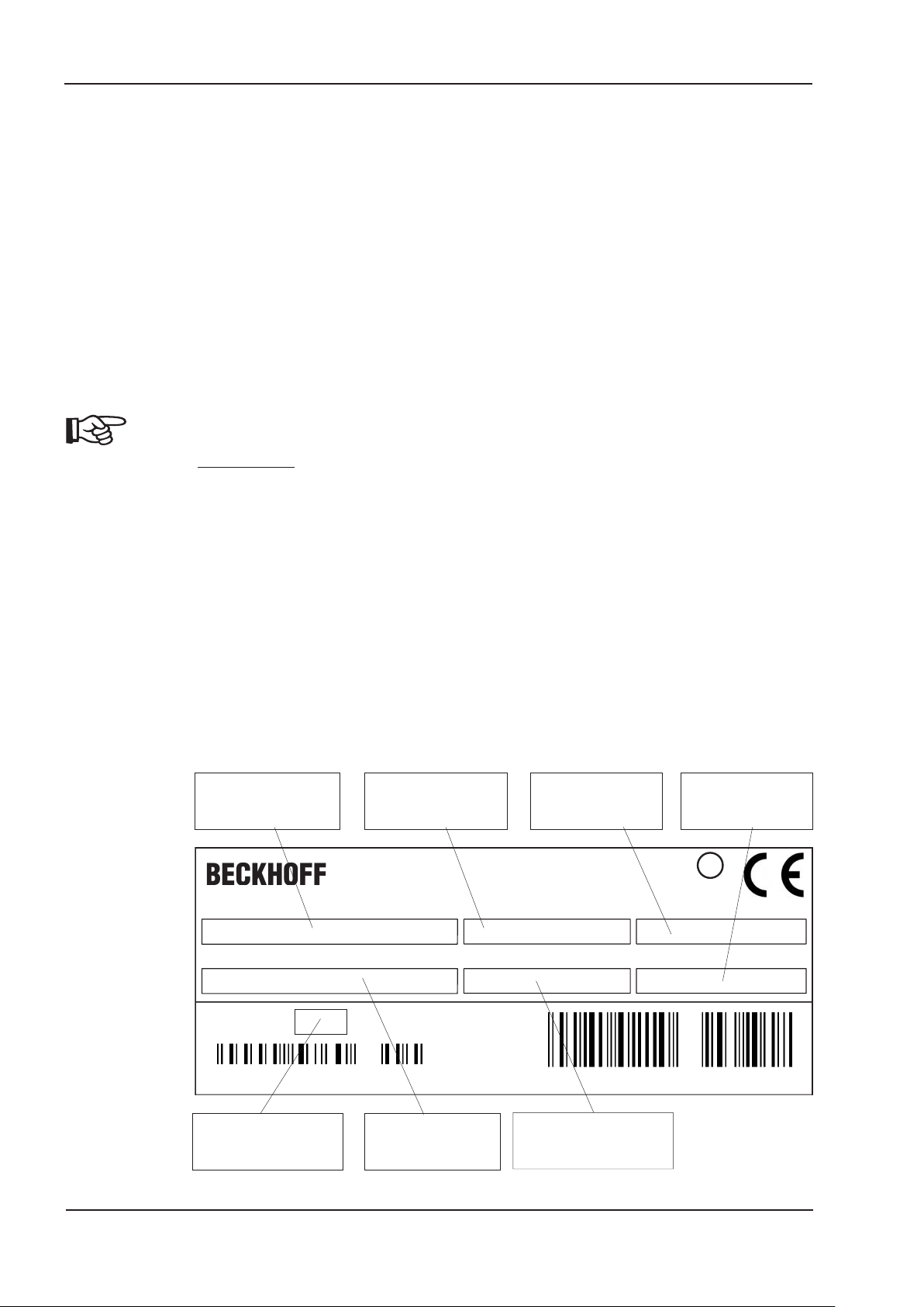
5.2 Nameplate
The nameplate depicted below is attached to the side of the servo amplifier.
Servo amplifier type
Typenbezeichnung
(must be ordered separately if required)
Eiserstr. 5
D-33415 Verl
Model Number
Tel.: +49-(0)5246/963-0
Fax: +49-(0)5246/963-149
Ser.Nr
CommentsSerial number
E217428
Ser.No.
Bemerkung
Enclosure Rating
U
CUS
L
®
LISTED
IND. CONT. EQ.
1VD4
Comment
Spannungsversorgung
Umgebungstemp.
Ambient temp.
008102106842
max. ambient
temperature
Power Supply
Nennstrom
Electrical supply
Installed load
Nom. Current
Output current
in S1 operation
Schutzart
5.76
Encl.Rating
14 AX2500 Product Manual
Page 15
BECKHOFF 06/2007 Package
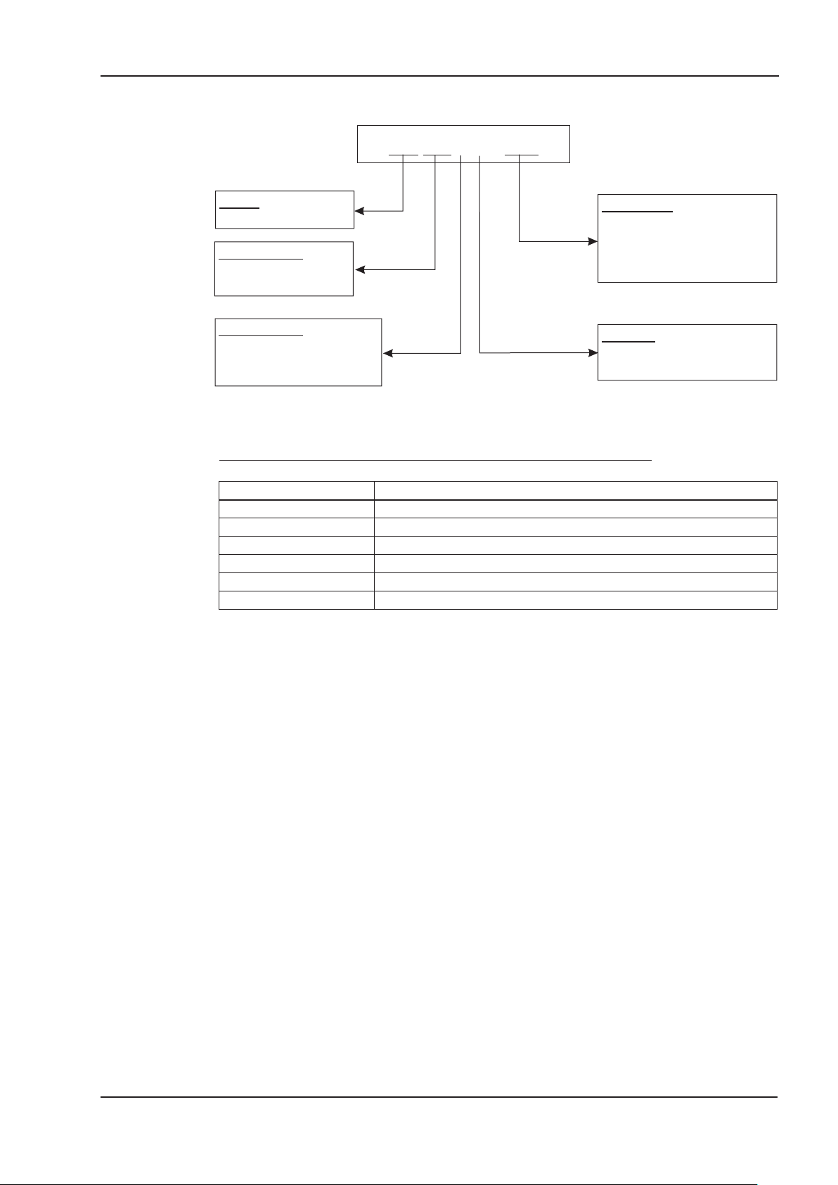
5.3 Part number scheme
S406A0-NA
Family
S4 AX2500
Current rating
03 3A rms
06 6A rms
Voltage rating
A 230...400V
6 115...230V
B no power supply
Expansions
NA no expansion
PB PROFIBUS
SE SERCOS
EC ETHERCAT
Function
A Axis module
M Master module
Comparison (without expansion) device name -> UL part number
Device Name UL Part Number
AX2503 S4036M-NA
AX2506 S4066M-NA
AX2513 S403AM-NA
AX2516 S406AM-NA
AX2523 S403BA-NA
AX2526 S406BA-NA
AX2500 Product Manual 15
Page 16

Technical description 06/2007 BECKHOFF
6 Technical description
6.1 Digital servo amplifiers in the series AX2500
Minimum complexity
up to 8 axes in a single system
l
only one power supply feed and one auxiliary voltage supply per system
l
shield connection directly on the servo amplifier
l
all axes in a system can be parameterized through a single interface
l
strongly reduced wiring expenditure by modular structure
l
simple mechanical structure on DIN rails
l
Standard version
2 supply voltage versions: AX250x up to 3x230VAC and
l
AX251x up to 3x400VAC
one size for the master and axis modules each, see page 35
l
analog input
l
fieldbus interface is integrated (standard: CANopen)
l
RS232 is integrated
l
pulse-direction interface is integrated
l
Supply power
l
directly off electrical supply input (master only, B6 rectifier bridge,
integral power input filter and inrush circuit):
1 x 115V AC (AX250x only, unearthed operation is permitted)
3 x 115V AC (AX250x only, unearthed operation is permitted)
1 x 230V AC (AX250x only, unearthed operation is permissible)
3 x 230V AC (all types, unearthed operation is permissible)
3 x 400V AC (AX251x only, TN-system or TT-system with
earthed neutral point)
l
fusing (e.g. fusible cutout) provided by the user
l
integrated interference suppression filter for the supply input (for category 2)
l
integrated interference suppression filter for the 24V auxiliary supply (for category 2)
l
all shielding connections directly on the amplifier
l
output stage IGBT module with isolated current measurement
Clock frequency can be switched from 8 to 16 kHz with
ASCII command (with power reduction, please contact
our customer support)
l
regen circuit internal regen resistor as standard,
external regen resistor if required
l
DC Bus link voltage 160...320V DC for AX250x
320...560V DC for AX251x
160...560V DC for AX252x
16 AX2500 Product Manual
Page 17

BECKHOFF 06/2007 Technical description
Integrated safety
safe electrical separation to EN 50178 between the power input / motor connections
l
and the signal electronics, provided by appropriate creepage distances and complete
electrical isolation
Soft-start, overvoltage detection, short-circuit protection, phase-failure monitoring
l
temperature monitoring of servo amplifier and motor (when using our motors with our
l
pre-assembled cables)
Auxiliary voltage 24V DC
electrically isolated via an external 24V DC PSU, e.g. with isolating transformer
l
Operation and parameter setting
with the comfortable setup software, via the serial interface of a PC to a single con
l
nection for all axes in a system
station address setting through two keys and a 3-digit LED status display on the
l
master
fully programmable via RS232 interface
l
-
Completely digital control
digital current controller (space vector pulse-width modulation, 62.5 µs)
l
freely programmable digital speed controller (62.5 µs or 250 µs)
l
integral position controller, with adaptation possibilities for every application (250 µs)
l
l
integrated pulse direction interface, for connection of a servomotor to a
stepper-motor control
l
evaluation of the resolver signals or sine/cosine signals from a high-resolution
encoder
l
encoder emulation (incremental ROD 426-compatible or SSI)
Comfort functions
l
4 programmable digital inputs
(two are normally defined as limit-switch inputs)
l
2 programmable digital outputs
l
freely programmable combinations of all digital signals
Options
l
PROFIBUS DP interface instead of CANopen, see page 69
l
SERCOS interface instead of CANopen, see page 70
l
EtherCat interface instead of CANopen, see page 71
AX2500 Product Manual 17
Page 18

Technical description 06/2007 BECKHOFF
6.2 Technical data
6.2.1 Rated data
max. 230VAC max. 400VAC
Master
AX250
Rated data DIM 363636
Rated supply voltage V~
Max. installed load for S1 operation
(in a multi-axis system)
kVA 7 12 —
1 x 115V
3 x 230V
-10%
to
+10%
Rated DC Bus link voltage V= 160 - 320 320 - 560 160 - 560
Rated output current
(rms value, ± 3%, @ 8kHz)
Peak output current
(max. ca. 5s, ± 3%, @ 8kHz)
Arms
Arms
36*36*36*
9 12* 9 12* 9 12*
8 (can be switched to 16, with power re-
Clock frequency of output stage kHz
duction, please contact our customer sup
Overvoltage switch-off threshold V 450 750 —
maximum load inductance mH 75 40 75 40 75 40
minimum load inductance mH 12 7.5 12 7.5 12 7.5
Form factor of the output current
(rated conditions and min. load
— 1.01
inductance)
Bandwidth of subordinate current
controller
Residual voltage drop at rated
current
Quiescent dissipation, output stage
disabled
Dissipation at rated current
(without regen dissipation)
kHz > 1.2
V<5
W121512151215
W356035603040
Mechanical
Weight kg 3 1.7
Height, without connectors mm 230 267* 230 267* 230 267*
Width mm 100 50
Depth, without connectors mm 240
Master
AX251
3 x 230V
to
3 x 400V
port)
Axis module
AX252
-10%
—
+10%
-
* with add-on ventilation, see page 36
18 AX2500 Product Manual
Page 19

BECKHOFF 06/2007 Technical description
6.2.2 Inputs / Outputs
Analog input, 14-bit resolution V
common-mode voltage max. V
Digital control inputs V low 0...7V, high 12...36V, 7mA
Digital control outputs, open emitter V max. 30V, 10mA
BTB/RTO output, relay contacts
Auxiliary supply, electrically isolated,
without holding brake, without fan
Auxiliary supply, electrically isolated,
with holding brake or fan
(check voltage drop !)
Min./max. output current for holding brake A 0.15 / 1.5
Connections
Control signals — Combicon spring terminal
Power supply — Power Combicon
Motor — Combicon
Resolver input — SubD 9pol. (socket)
Incremental encoder input — SubD 15pol. (socket)
PC interface — SubD 9pol. (plug)
Encoder emulation, ROD/SSI — SubD 9pol. (plug)
n= number of axes
6.2.3 Recommended tightening torques
±10
±10
V DC max. 30, AC max 42
mA 500
V 20-30
A n * 0.5
V 24 (-0% +15%)
A n * 2,5
Connector Tightening torque
X1, X3, X6 0.3 Nm
X0 1.3 Nm
Earthing bolts 3.5 Nm
lower mounting bolt 3.5 Nm
6.2.4 Fusing
Internal fusing
Function
Auxiliary supply 24V 20 AM
Regen resistor electronical
External fusing
Function Fusible cutouts or similar
AC supply F
24V supply F
Regen resistor F
N1/2/3
H1/2
B1/2
16 A slow
20 A slow
6 A slow
AX2500 Product Manual 19
Page 20
Technical description 06/2007 BECKHOFF
6.2.5 Ambient conditions, ventilation, mounting position
Storage, transport
ð p.13
Supply voltage tolerances
main power
AX250x
AX251x
min 1x115V
min 3x115V
min 3x230V
AC / max 1x230V
-10%
AC / max 3x230V
-10%
AC / max 3x400V
-10%
+10%
, 50/60 Hz
+10%
, 50/60 Hz
+10%
, 50/60 Hz
auxiliary supply
w/o brake and w/o fan
with brake or with fan
Ambient temperature in operation
Humidity in operation
Site altitude
20 VDC ... 30 VDC
24 VDC (-0% +15%), check voltage drop
0...+45
o
C at rated conditions
+45...+55°C with power derating 2.5% / K
rel. humidity 85%, no condensation
up to 1000m amsl without restrictions
1000...2500m amsl with derating 1.5% / 100m
Pollution level Pollution level 2 as per EN 60204 / EN 50178 Vibrations Noise emission
Class 3111 according to IEC 721-3-3
max. 45 dB(A)
Enclosure protection IP 20 Mounting position
Ventilation
normally vertical ð p.34
AX25x3: free convection
AX25x6: add-on fan (ð p.36)
Make sure that there is adequate forced ventilation in the closed control cabinet.
6.2.6 Conductor cross-sections
Technical requirements to cables ð p.41.
Following EN 60204-1, we recommend :
AC connection
Motor cables, max. 25m
Resolver, motor thermostat,
max.100m
Encoder, motor thermostat,
max. 50m
Analog signals
Control signals, BTB, DGND
Holding brake (motor)
+24 V / XGND
To reach the max. permitted cable length, observe cable requirements ð p. 41.
6.3 LED display
A 3-digit LED display indicates the amplifier status after switching on the 24V supply
(ð p.89).
1.5 mm², depending on the system fusing
1 mm², shielded, capacitance <150pF/m
4x2x0.25 mm², twisted pairs, shielded,
capacitance <120pF/m
7x2x0.25 mm², twisted pairs, shielded,
capacitance <120pF/m
0.25 mm² , twisted pairs, shielded
0.5 mm²
0.75 mm², shielded, check voltage drop
max. 2.5 mm²
Check voltage drop and total current!
20 AX2500 Product Manual
Page 21
BECKHOFF 06/2007 Technical description
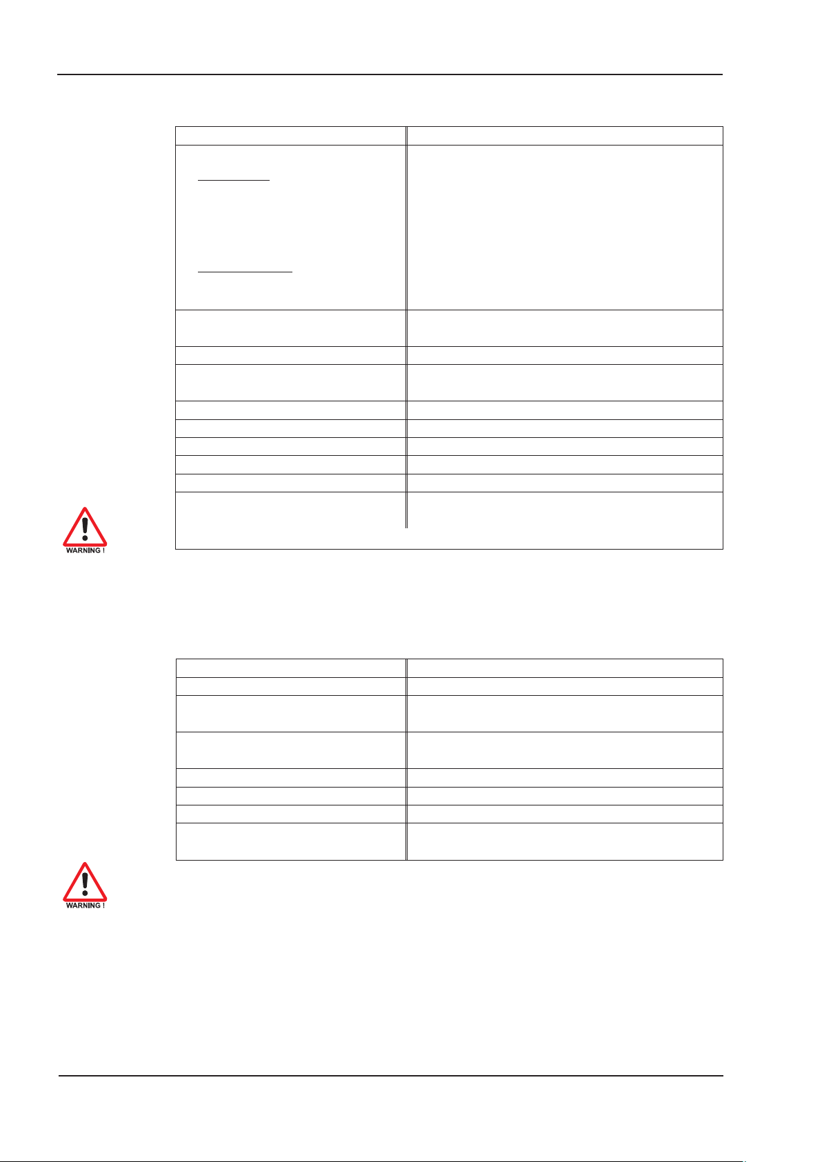
6.4 Control for motor holding brake
A motor holding brake (24V, max.1.5 A) can be controlled directly by the servo amplifier.
Check voltage drop, measure the voltage at brake input and check brake function
(brake and no brake).
This function does not ensure personnel safety!
The brake function must be enabled through the BRAKE parameter (on the screen page
for Motor): the setting is WITH.
In the diagram below you can see the timing and functional relationships between the
ENABLE signal, speed setpoint, speed and braking force.
During the internal enable delay time of 100 ms (DECDIS) the speed setpoint of the servo
amplifier is internally driven down a 10 ms ramp to 0. The brake output is switched on
when a speed of 5 rpm is reached, at the latest after 5s (EMRGTO).
The rise (f
) and fall (f
brH
) times of the holding brakes that are built into the motors vary
brL
for the different types of motor (see motor manual). A description of the interface can be
found on page 48.
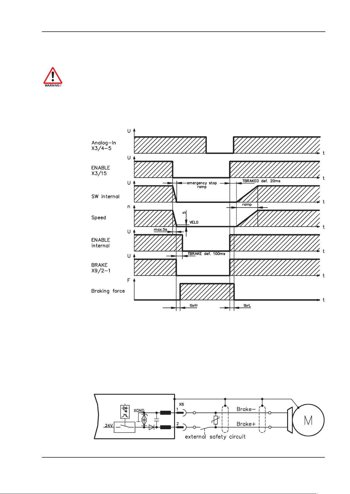
Personnel-safe operation of the holding brake requires an additional “make” contact in
the brake circuit and a spark suppressor device (e.g. a varistor) in the recommended
brake circuit:
AX2500
AX2500 Product Manual 21
Page 22

Technical description 06/2007 BECKHOFF
6.5 Grounding system
AGND – ground reference for analog signals, internal analog ground
DGND – ground reference for digital signals and auxiliary supply voltage,
optically isolated
PGND — ground reference for position output
The electrical isolation is indicated in the block diagram (ð p.43).
6.6 Regen circuit
During braking with the aid of the motor, energy is fed back to the servo amplifier. This
energy is converted into heat in the regen resistor. The regen resistor is switched in and
out by the regen circuit. The switching thresholds for the regen circuit are adjusted to suit
the supply voltage with the aid of the setup software.
Our customer support can help you with the calculation of the regen power which is
required. A description of the interface can be found on page 48 .
Internal regen resistor 33 W
External regen resistor 33 W
Functional description
The regen circuit starts to respond when the DC Bus link voltage reaches the set value.
If the energy which is fed back from the motor, as an average over time or as a peak
value, is higher than the preset regen power, then the servo amplifier will output the status regen power exceeded and the circuit will be switched off.
At the next internal check of the DC Bus link voltage (after a few milliseconds) an
overvoltage will be detected and the servo amplifier will be switched off, with the error
message overvoltage (ð p.90).
The BTB/RTO contact (terminals X1/1,2) will be opened simultaneously (ð p.66).
Technical data
Supply voltage Rated data DIM Value
Upper switch-on threshold for regen circuit V 400
Switch-off threshold for regen circuit V 380
)W55
Bint
) max. kW 0,4
W
33
3 x 230 V
Continuous int. power in regen circuit (R
Continuous ext. power in circuit (R
Pulse power, internal (R
Pulse power, external (R
max. 1s) kW 4.8
Bint
Bext
Bext
max. 1s) kW 4.8
External regen resistor
Upper switch-on threshold for regen circuit V 720
Switch-off threshold for regen circuit V 680
)W80
Bint
) max. kW 0,6
W
33
3 x 400 V
Continuous int. power in regen circuit (R
Continuous ext. power in circuit (R
Pulse power, internal (R
Pulse power, external (R
max. 1s) kW 16
Bint
Bext
Bext
max. 1s) kW 16
External regen resistor
22 AX2500 Product Manual
Page 23

BECKHOFF 06/2007 Technical description
6.7 Switch-on/-off behavior
This chapter describes the switch-on and switch-off behavior of the AX25 and the steps
required to achieve operational stopping or emergency stop behavior that complies with
standards.
The servo amplifier’s 24 V supply must remain constant. The ASCII commands
ACTFAULT (error response) and STOPMODE (ENABLE signal response) dictate
how the drive will behave.
STOPMODE ACTFAULT
0 (default) 0
1 1 (default)
Behavior during a power failure
The servo amplifiers use an integrated circuit to detect if one or more input phases
(power supply feed) fail. The behavior of the servo amplifier is set using the setup soft
ware: Under “Response to Loss of Input Phase” (PMODE) on the Basic Setup screen,
select:
Warning if the higher-level control system is to bring the drive to a standstill: War
l
ning n05 is output if an input phase is missing, and the motor current is limited to 4 A.
The servo amplifier is not disabled. The higher-level control system can now selectively end the current cycle or start bringing the drive to a standstill. Therefore, the error message “MAINS BTB, F16" is output on a digital output of the servo amplifier
and evaluated by the control system, for instance.
l Error message if the servo amplifier is to bring the drive to a standstill: Error messa-
ge F19 is output if an input phase is missing. The servo amplifier is disabled and the
BTB contact opens. Where the factory setting is unchanged (ACTFAULT=1), the motor is braked using the set “EMERGENCY STOP RAMP”.
Behavior (see also ASCII reference in the online help of
the setup software)
Motor coasts to a standstill in an uncontrolled manner
Motor is braked in a controlled manner
-
-
Behavior when undervoltage threshold is reached
If the undervoltage threshold is undershot in the DC bus link (the threshold value
depends on the type of servo amplifier), the error message “UNDERVOLTAGE, F05" is
displayed. The drive response depends on the ACTFAULT/STOPMODE setting.
Behavior with enabled “holding brake” function
Servo amplifiers with an enabled holding brake function have a special procedure for
switching off the output stage ( ð p. 21). Removing the ENABLE signal triggers electrical
braking.
As with all electronic circuits, the general rule applies that there is a possibility of the inter
nal “holding brake” module failing. Bringing a motor to a standstill using a holding brake in
a way that is personnel safe also requires an electromechanical “make” contact for the
holding equipment and a suppressor device for the brake.
-
AX2500 Product Manual 23
Page 24
Technical description 06/2007 BECKHOFF
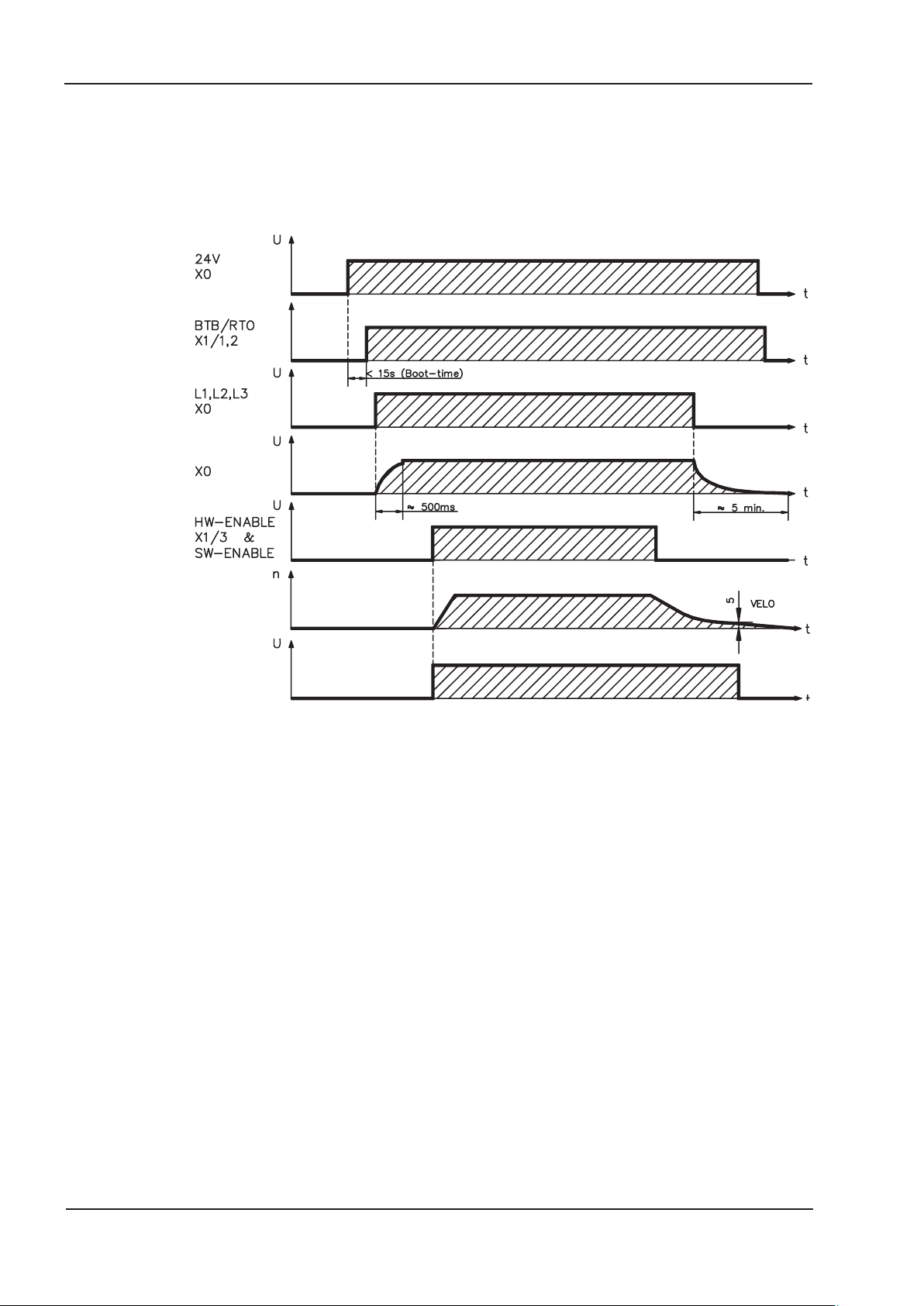
6.7.1 Behavior in standard operation
The behavior of the servo amplifier always depends on the current setting of a number of
different parameters (e.g., ACTFAULT, VBUSMIN, VELO, STOPMODE, etc.; see online
help). The diagram below illustrates the correct functional sequence for switching the
servo amplifier on and off.
DC-BUS link
Motor speed
Power stage
Enable (internal)
Devices which are equipped with a selected “Brake” function use a special sequence for
switching off the output stage (ð p.21).
24 AX2500 Product Manual
Page 25
BECKHOFF 06/2007 Technical description
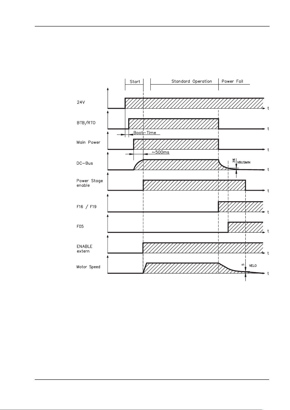
6.7.2 Behavior in the event of an error (with standard setting)
The behavior of the servo amplifier always depends on the current setting of a number of
different parameters (e.g., ACTFAULT, VBUSMIN, VELO, STOPMODE, etc.; see online
help). The diagram shows the startup procedure and the procedure that the internal con
trol system follows in the event of one or more electrical supply phases failing, assuming
that the standard parameter settings apply.
-
(F16/F19 = error messages Mains BTB /input phase, F05 = error message Undervoltage)
Even if there is no intervention from an external control system (in the example, the
ENABLE signal remains active), the motor is immediately braked using the emergency
stop ramp if an input phase error is detected and assuming that no changes have been
made to the factory setting (ACTFAULT=1).
AX2500 Product Manual 25
Page 26

Technical description 06/2007 BECKHOFF
6.8 Stop / Emergency Stop Function to EN 60204
6.8.1 Stop: Standards
The Stop function is used to shut down the machine in normal operation. The Stop func
tions are defined by EN 60204 (VDE 0113), paragraphs 9.2.2 and 9.2.5.3.
Category 0: Shut-down by immediate switching-off of the energy supply to the
drive machinery (i.e. an uncontrolled shut-down);
Category 1: A controlled shut-down , whereby the energy supply to the drive
machinery is maintained to perform the shut-down, and the energy
supply is only interrupted when the shut-down has been completed;
Category 2: A controlled shut-down, whereby the energy supply to the drive
machinery is maintained.
The parameters “STOPMODE” and “ACTFAULT” must be set to 1 in order to
implement the stop categories. If necessary, change the parameters via the
terminal screen of the setup software and store the data in the EEPROM.
The Stop Category must be determined by a risk evaluation of the machine. In addition,
suitable means must be provided to guarantee a reliable shut-down.
Category 0 and Category 1 Stops must be operable independently of the operating mode,
whereby a Category 0 Stop must have priority. Stop functions must be implemented by
disconnection of the appropriate circuitry, and have priority over assigned start functions.
If necessary, provision must be made for the connection of protective devices and
lock-outs. If applicable, the Stop function must signal its status to the control logic. A reset
of the Stop function must not create a hazardous situation.
-
26 AX2500 Product Manual
Page 27

BECKHOFF 06/2007 Technical description
6.8.2 Emergency Stop: Standards
The emergency Stop function is used for the fastest possible shut-down of the machine
in a dangerous situation. The Emergency Stop function can be triggered by the actions of
a single person. It must be fully functional and available at all times. The user must not
have to work out how to operate this mechanism. The Emergency Stop function is
defined by EN 60204 (VDE 0113), paragraph 9.2.5.4.
In addition to the requirements for Stop, the emergency Stop must fulfil the following
requirements:
emergency stop must have priority over all other functions and controls in all opera
l
ting situations.
the energy supply to any drive machinery that could cause dangerous situations
l
must be switched off as fast as possible, without causing any further hazards (e.g. by
using mechanical latching devices that do not require an external supply of energy,
by counter-current braking in Stop Category 1).
the reset must not initiate a restart.
l
If necessary, provision must be made for the additional connection of emergency stop
devices (see EN 60204, "Requirements for emergency stop devices"). The Emergency
Stop must be effective as a stop of either Category 0 or Category 1.
The Emergency Stop Category must be determined by a risk evaluation of the machine.
-
Category 0
Only hard-wired, electromechanical components may be used for the Category 0 Emergency Stop function. It must not be triggered using switching logic (hardware or software),
by transferring commands via a communication network, or via a data link.
The drive must be shut down using an electromechanical circuit. If the connected servo
motor has an integrated brake, this must always be controlled by an electromechanical
circuit as well.
Category 1
With the Category 1 Emergency Stop function, there must be absolute certainty in terms
of the power supply for the machine drives being switched off (i.e., secured) using elec
tromechanical components. Additional Emergency Stop equipment may be connected.
Bringing the motor to a standstill by interrupting the mains supply and using controlled
electronic braking. The 24 V supply for the servo amplifier must remain constant. The
issue of which circuit should be used is highly dependent on the requirements of the
application at hand.
Usually a brake in a servo motor only has the function of a holding brake. To ensure an
emergency stop function, the braking torque that is required must be checked. If the hold
ing brake fulfills the dynamic requirements, it must be taken into acount that this applica
-
tion will cause increased wear.
The parameters “STOPMODE” and “ACTFAULT” must be set to 1 in order to
implement the stop categories. If necessary, change the parameters via the
terminal screen of the setup software and store the data in the EEPROM.
-
AX2500 Product Manual 27
Page 28
Technical description 06/2007 BECKHOFF
6.8.3 Implementation of the Stop Category 0
Bringing the motor to a standstill by immediately switching off the amplifier power supply
(STOPMODE & ACTFAULT parameters set to 1). The switching sequence is unambig
uously fixed by the circuit, and must be followed, to prevent undesirable error signals and
failure of the servo amplifier.
It is not possible to achieve a Category 0 shut-down with the servo amplifier alone, since
hard-wired electromechanical components are compulsory for this type of disconnection.
A brake that is built into the motor must have an additional electromechanical control cir
cuit, as well as the control through the AX25xx, in order to meet Category 0.
Normally, a brake in a servo motor only has the function of a holding brake. To ensure an
emergency stop function, the braking torque that is required must be checked. If the hold
ing brake fulfills the dynamic requirements, it must be taken into acount that this applica
tion will cause increased wear.
Circuit suggestion
(with EMERGENCY STOP Category 0, control function with contactor relays)
-
-
-
-
AX2500
28 AX2500 Product Manual
Page 29
BECKHOFF 06/2007 Technical description
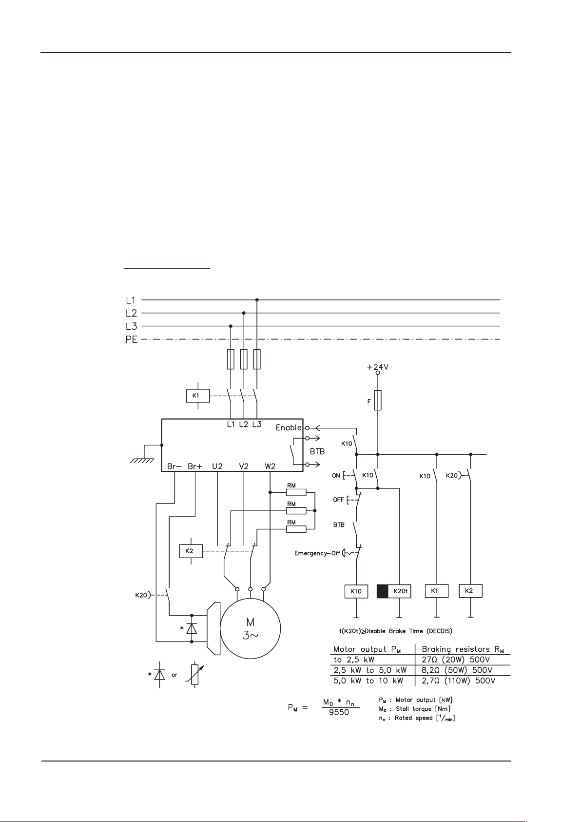
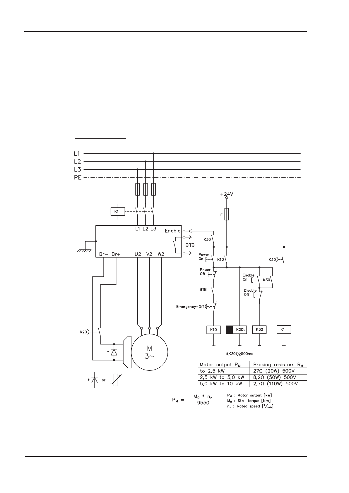
6.8.4 Implementation of the Stop Category 1
Bringing the motor to a standstill by interrupting the mains supply and using controlled
electronic braking (STOPMODE & ACTFAULT parameters set to 1). The 24 V supply
for the AX2500 must remain constant.
The drive is braked in a controlled manner during the stopping (disabling) procedure. If
the speed VEL0 (see sequence diagram in chapter 6.4) is undershot, the holding brake is
applied and the output stage is disabled.
As soon as two separate time periods (set at the time relay) have elapsed, the mains sup
ply and the holding brake are electrically isolated.
Should an internal AX2500 fault occur, the motor is forced to a standstill once K20
drops out.
Circuit suggestion
(with EMERGENCY STOP Category 1, control function with contactor relays)
AX2500
-
AX2500 Product Manual 29
Page 30
Technical description 06/2007 BECKHOFF
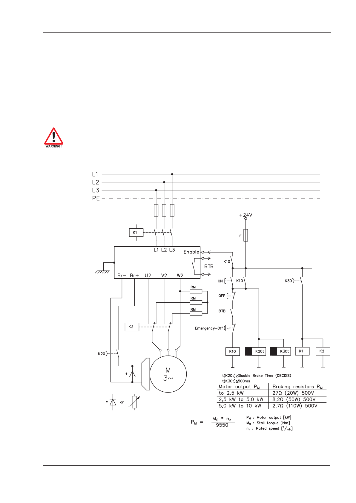
6.8.5 Implementation of the Stop Category 2
The machine receives an operational stop (disable) command and brakes the drive using
the set braking ramp (STOPMODE & ACTFAULT parameters set to 1).
The drive is braked in a controlled manner during the stopping (disabling) procedure. If
the speed VEL0 (see sequence diagram in chapter 6.4) is undershot, the holding brake is
applied and the output stage is disabled. In this case, there is no interruption of the elec
trical supply.
If the electrical supply is switched off, not only will the controlled braking procedure be
performed, but the mains supply and the holding brake will also be electrically isolated fol
lowing a time period set at the time relay.
Circuit suggestion
(with EMERGENCY STOP Category 1, control function with contactor relays)
-
-
AX2500
30 AX2500 Product Manual
Page 31

BECKHOFF 06/2007 Technical description
6.9 Shock-hazard protection
6.9.1 Leakage current
Leakage current via the PE conductor results from the combination of equipment and
cable leakage currents. The leakage current frequency pattern comprises a number of
frequencies, whereby the residual-current circuit breakers definitively evaluate the 50Hz
current. For this reason, the leakage current cannot be measured using a conventional
multimeter.
As a rule of thumb, the following assumption can be made for leakage current on our
low-capacity cables at a mains voltage of 400 V, depending on the clock frequency of the
output stage:
I
= n x 20mA + L x 1mA/m at 8kHz clock frequency at the output stage
leak
= n x 20mA + L x 2mA/m at a 16kHz clock frequency at the output stage
I
leak
(where Ileak=leakage current, n=number of amplifiers, L=length of motor cable)
At other mains voltage ratings, the leakage current varies in proportion to the voltage.
Example: 2 x servo amplifiers + a 25m motor cable at a clock frequency of 8kHz:
2 x 20mA + 25m x 1mA/m = 65mA leakage current.
Since the leakage current to PE is more than 3.5 mA, in compliance with EN50178
the PE connection must either be doubled or a connecting cable with a
cross-section >10mm² must be used. Use the PE terminal X0/3 and the PE bolt in
order to fulfil this requirement.
The following measures can be used to minimise leakage currents.
— Reduce the length of the engine cable
— Use low-capacity cables (see p.41)
— Remove external EMC filters (radio-interference suppressors are integrated)
6.9.2 Residual-current circuit breakers (FI)
In conformity with DIN IEC 60364-4-41 – Regulations for installation and EN 60204 –
Electrical equipment of machinery, residual-current circuit-breakers (called FI below) can
be used provided the requisite regulations are complied with.
The AX2500 is a 3-phase system with a B6 bridge. Therefore, FIs which are sensitive
to all currents must be used in order to detect any D.C. fault current. Refer to chapter
6.9.1 for the rule of thumb for determining the leakage current.
Rated residual currents in the FI
10 -30 mA
50 -300 mA
Recommendation: In order to protect against direct contact (with motor cables
shorter than 5 m) we recommend that each servo amplifier be protected
individually using a 30mA residual-current circuit-breaker which is sensitive to all
currents.
Protection against "indirect contact" (personal fire protection) for stationary
and mobile equipment, as well as for "direct contact".
Protection against "indirect contact" (personal fire protection) for stationary
equipment
If you use a selective FI circuit-breaker, the more intelligent evaluation process will pre
vent spurious tripping of the circuit-breakers.
-
AX2500 Product Manual 31
Page 32

Technical description 06/2007 BECKHOFF
6.9.3 Isolating transformers
If protection against indirect contact is absolutely essential despite a higher leakage cur
rent, or if an alternative form of shock-hazard protection is sought, the AX2500 can also
be operated via an isolating transformer.
A ground-leakage monitor can be used to monitor for short circuits.
We would advise you to keep the length of wiring between the transformer and the
servo amplifier as short as possible.
-
32 AX2500 Product Manual
Page 33

BECKHOFF 06/2007 Mechanical Installation
7 Mechanical Installation
7.1 Important notes
Protect the servo amplifier from impermissible stresses. In particular, do not let any
l
components become bent or any insulation distances altered during transport and
handling. Avoid contact with electronic components and contacts.
Ensure that there is an adequate flow of cool, filtered air into the bottom of the control
l
cabinet or use heat exchanger. Note the conditions on page 20.
Take care that the servo amplifier and motor are properly earthed. Do not use pain
l
ted (non-conductive) mounting plates.
Don't mount devices, which produce magnetic fields, directly beside the servo ampli
l
fier. Strong magnetic fields could directly affect internal components. Install devices
which produce magnetic field with distance to the servo amplifiers and/or shield the
magnetic fields.
Not more than 7 axis modules can be connected to a master module.
l
7.2 Guide to mechanical installation
The following notes should assist you to carry out the mechanical installation in a sensible sequence, without overlooking anything important:
In a closed control cabinet. Observe page 20.
Site
Ventilation
The site must be free from conductive or corrosive materials.
For the mounting position within the cabinet ð p.34
Check that the ventilation of the servo amplifier is unimpeded
and keep within the permitted ambient temperature ð p.20 .
Keep the required space clear above and below the
servo amplifier ð p.34.
-
-
Mount the servo amplifier on mounting rails (DIN-rails) on the
Mounting
Grounding,
Shielding
conductive, earthed mounting plate in the control cabinet and
mount the necessary add-on fans (ð p.36)
EMC-conform shielding and grounding (ð p.45) Earth the moun
ting plate, motor housing and CNC-GND of the controls. Notes
on connection techniques are on page 40
-
AX2500 Product Manual 33
Page 34

Mechanical Installation 06/2007 BECKHOFF
7.3 Mounting
Material: 2 mounting rails to EN60715, min. length = system width + 40mm,
make sure there is a conductive connection to the mounting plate
Mount the protective cover (7mm) on the left side of the system.
Tools required: Screwdriver with approx. 5 mm blade width
AX2500
34 AX2500 Product Manual
Page 35

BECKHOFF 06/2007 Mechanical Installation
7.4 Dimensions
AX250x and AX251x
AX252x
AX2500 Product Manual 35
Page 36

Mechanical Installation 06/2007 BECKHOFF
7.5 Add-on fan
Electrical add-on fan for two axes to achieve rated power even under unfavourable ambi
ent conditions, required for AX25x6.
-
To mount the fan, just hook it in the designated slots at the bottom of the AX2500 and
screw the fixing bolt into the thread in the housing. The electrical connection takes place
automatically when mounting the fan.
Please consider that a mounted fan increases the required space underneath the
amplifier! (Þ p. 34)
The drawing below shows, how the fan should be mounted. With an odd number of axes
(master included), the fan must also cover the power supply unit at the master.
Single master
Master with 1 Axis module
Master with 2 Axis modules
36 AX2500 Product Manual
Page 37

BECKHOFF 06/2007 Electrical Installation
8 Electrical Installation
8.1 Important notes
Not more than 7 axis modules can be connected to a master module.
l
Check the combination of servo amplifier and motor. Compare the rated voltage and
l
current of the units. Carry out the wiring according to the instructions on page 39.
Make sure that the maximum permissible rated voltage at the terminals for L1, L2, L3
l
and +R
conditions (see EN 60204-1 Section 4.3.1). An excessive voltage on these terminals
can lead to destruction of the regen circuit and the servo amplifier.
Use the AX251x only on an earthed 3-phase supply system. Use the amplifier only to
drive a synchronous servomotor.
The fusing of the AC supply input and the 24V supply is installed by the user
l
(ð p.19).
Route power and control cables separately. We recommend a separation of at least
l
20 cm. This improves the interference immunity required by EMC regulations. If a
motor power cable is used which includes cores for brake control, the brake control
cores must be separately shielded. Earth the shielding at both ends (ð p.45).
, –DC is not exceeded by more than 10%, even in the most unfavourable
Bext
Install all heavy-current cables with an adequate cross-section, as per EN 60204-1
l
(ð p.20) and use the requested cable material (ð p. 41) to reach max. cable length.
Wire the BTB/RTO contact in series into the safety circuit of the installation.
l
Only in this way is the monitoring of the servo amplifier assured.
Install all shielding with large area (low impedance) connections, with metallised con-
l
nector housings or shield connection clamps where possible.
Notes on connection techniques can be found on page 40.
l
It is permissible to alter the servo amplifier settings by using the operator software.
Any other alterations will invalidate the warranty.
Caution
Never disconnect the electrical connections to the servo amplifier while it is live.
Residual charges in the capacitors can have dangerous levels up to 300 seconds
after switching off the mains supply voltage. Measure the voltage in the DC Bus
link (+R
/-DC) and wait until the voltage has fallen below 40V.
Bext
Control and power connections can still be live, even when the motor is not
rotating.
AX2500 Product Manual 37
Page 38

Electrical Installation 06/2007 BECKHOFF
8.2 Guide to electrical installation
The following notes should assist you to carry out the electrical installation in a sensible
sequence, without overlooking anything important:
Cable selection
Grounding,
Shielding
Wiring — Route power leads separately from control cables
Select cables according to EN 60204-1, ð p.20
EMC-conform shielding and grounding (ð p.45) Earth the moun
ting plate, motor housing and CNC-GND of the controls. Notes
on connection techniques are on page 40
— Wire the BTB/RTO contact in series into the safety loop
— Connect the digital control inputs to the servo amplifier
— Connect up AGND
— Connect the analog setpoint, if required
— Connect the feedback unit (resolver or encoder)
— If required, connect the encoder emulation
— If required, connect the fieldbus
— Connect the motor cable
Connect shielding to EMC connectors at the motor end, and
the shielding lug at the amplifier end
— Connect motor-holding brake, with shielding to EMC
connector at the motor end, and to shielding lug at the
amplifier end
— If required, connect the external regen resistor (with fusing)
— Connect the auxiliary supply
(maximum permissible voltages ð p.20)
— Connect main power supply
(maximum permissible voltages ð p.20)
— Connect PC (ð p.67).
-
Check
Make a final check of the wiring carried out against the wiring
diagrams that have been used
38 AX2500 Product Manual
Page 39

BECKHOFF 06/2007 Electrical Installation
8.3 Wiring
8.3.1 Important notes
Only professional staff who are qualified in electrical engineering are allowed to
install the servo amplifier.
The installation procedure is described as an example. A different procedure may be
appropriate or necessary, depending on the application of the equipment.
We provide further know-how through training courses (on request).
Caution !
Only install and wire up the equipment when it is not live, i.e. when neither the
mains power supply nor the 24 V auxiliary voltage nor the operating voltages of
any other connected equipment is switched on.
Take care that the cabinet is safely disconnected (lock-out, warning signs etc.).
The individual voltages will be switched on for the first time during commissioning.
The ground symbol
that you must take care to provide an electrically conductive connection with the
largest possible area between the unit indicated and the mounting plate in the
control cabinet. This connection is for the effective grounding of HF interference,
and must not be confused with the PE symbol W (protective earth to EN 60204).
Use the following wiring and connection diagrams :
Overview:
Master module : Page 45
Axis module : Page 46
Mains power : Page 47
Motor : Page 48
Feedback : Page 49ff
Electronic Gearing / Master Slave
Master/slave : Page 56
Pulse/direction : Page 59
Encoder emulation:
ROD (A quad B) : Page 61
SSI : Page 62
Digital&Analog I/Os : Page 63ff
RS232 / PC : Page 67
Fieldbus:
CAN interface : Page 68
PROFIBUS interface : Page 69
SERCOS interface : Page 70
EtherCAT interface : Page 71
Multiaxis systems : Page 87
X, which you will find in all the wiring diagrams, indicates
AX2500 Product Manual 39
Page 40

Electrical Installation 06/2007 BECKHOFF
8.3.2 Shield connection on the front panel
The pre-assembled cables for
AX2500 are provided with an over
all metal ferrule at the amplifier end
that is electrically
connected to the shielding.
Thread a cable tie through each slot
in the shielding strip (front panel) of
the servo amplifier.
-
AX2500
AX2500
Tighten up the cable ties so that the
shielding ferrule and the sheathing
of the cable is pressed down tightly
against the shielding strip.
40 AX2500 Product Manual
Page 41

BECKHOFF 06/2007 Electrical Installation
8.3.3 Requirements to cables
Further information on the chemical, mechanical and electrical characteristics of the
cables can be obtained from our customer support.
Observe the restrictions in the chapter "Conductor cross-sections" on page 20.
To operate the amplifier with the max. permitted cable length, you must use cable
material which meets the requirements on the capacity given below.
Insulation material
Sheathing PUR (polyurethane, code 11Y)
Core insulation PETP (polyesteraphthalate, code 12Y)
Capacitance
Motor cable less than 150 pF/m
RES/encoder cable less than 120 pF/m
AX2500 Product Manual 41
Page 42

Electrical Installation 06/2007 BECKHOFF
8.4 Components of a servo system
PC
Control / PLC
24V supply
motor
fuses
drive
contactor
terminals
42 AX2500 Product Manual
Page 43

BECKHOFF 06/2007 Electrical Installation
8.5 Block diagram
The block diagram below just provides an overview.
AX2500 Product Manual 43
Page 44

Electrical Installation 06/2007 BECKHOFF
8.6 Connector assignments
44 AX2500 Product Manual
Page 45

BECKHOFF 06/2007 Electrical Installation
8.7 Connection diagram AX250x and AX251x (overview)
Follow the safety instructions (ð p.9)
and the use as directed (ð p.10) !
AX250x/AX251x
ðp.51ff
ð p.63
ð p.63
ð p.50
ð p.65
ð p.48
ð p.56
ð p.67
ð p.66
ð p.47
ð p.48
ð p.68
ð p.47
AX2500 Product Manual 45
Page 46

Electrical Installation 06/2007 BECKHOFF
8.8 Connection diagram AX252x (overview)
Follow the safety instructions (ð p.9)
and the use as directed (ð p.10) !
AX252x
ðp.51ff
ð p.63
ð p.63
ð p.50
ð p.65
ð p.48
ð p.56
ð p.68
46 AX2500 Product Manual
Page 47

BECKHOFF 06/2007 Electrical Installation
8.9 Power supply, master only
8.9.1 Mains supply connection (X0)
Three-phase supplies
Directly to earthed supply, filter is integrated, fusing (e.g. fusible cut-outs) to be provided
by the user (ð p.19).
AX2500
for AX250x
for AX251x
Single-phase supplies
Directly to supply, filter is integrated, fusing (e.g. fusible cut-outs) to be provided by the
user (ð p.19).
AX2500
8.9.2 24V auxiliary voltage (X0)
— Electrically isolated supply from an external 24 V DC PSU, e.g. with isolating
transformer
— Required current rating (ð p.19)
Observe summarized current and voltage drop!
— Integrated EMC filter for the 24 V auxiliary supply
AX2500
for AX250x
AX2500 Product Manual 47
Page 48

Electrical Installation 06/2007 BECKHOFF
8.10 DC Bus link (X0)
Can be connected in parallel with further, identical masters (via terminals -DC and RB
Only servo amplifiers with mains supply from the same mains (identical mains
supply voltage) may be connected by the DC bus link.
The sum of the rated currents for all of the servo amplifiers connected in parallel
to an AX2500 must not exceed 24 A.
Use unshielded single cores (2.5mm²) with a max. length of 200 mm. Use shielded
cables for longer lengths.
8.11 Motor connection with brake (X6)
Max. admisible length of the motor cable is 25 m.
AX2500
ext
).
8.12 External regen resistor (X0), master only
Remove the plug-on link between terminals X0/5 (-RB) and X0/4 (+R
AX2500
bint
).
48 AX2500 Product Manual
Page 49

BECKHOFF 06/2007 Electrical Installation
8.13 Feedback
Every closed servo system will normally require at least one feedback device for sending
actual values from the motor to the servo drive. Depending on the type of feedback
device used, information will be fed back to the servo amplifier using digital or analog
means.
AX2500 supports the most common types of feedback device whose functions must be
assigned with the parameters
FBTYPE (screen page FEEDBACK), primary Feedback
EXTPOS (screen page POSITION), secondary Feedback
GEARMODE (screen page GEARING), secondary Feedback
in the setup software. Scaling and other settings must always be made here.
Configuration Location
One Feedback
Two Feedbacks
For a detailed description of the ASCII parameters, please refer to the online help of the
setup software.
The table below provides an overview of the supported feedback types, their corresponding parameters and a reference to the relevant connection diagram in each case. On
each of these, the pin assignment shown on the encoder side relates to the BECKHOFF
motors.
Primary feedback type Connector
Resolver X5
SinCos Encoder BISS X2
SinCos Encoder ENDAT X2
SinCos Encoder HIPERFACE X2
SinCos Encoder w/o data channel X2
SinCos Encoder + Hall X2
RS422 5V X4
Sensorless (w/o feedback) - - 10*
motor FBTYPE
motor FBTYPE
externally
ASCII
Parameter
EXTPOS
GEARMODE
Commu-
tation
XXX
XX
Wiring
diagram
ð S.50
ð S.51
ð S.52
ð S.52
ð S.53
ð S.54
ð S.55
Speed
control
Position-
control
X
FBTYPE
0, 3
20*
3, 4
2, 3
6, 7 (16*)
11*
8*, 9*
electr.
gearing
X
* Can only be set on the terminal screen of the setup software
** RS422 means “incremental encoder AquadB”.
Hints for combining primary with secondary feedback systems for position
control/electr. gearing can be found from page 56.
AX2500 Product Manual 49
Page 50

Electrical Installation 06/2007 BECKHOFF
8.13.1 Resolver (X5)
Connection of a Resolver (2 to 36-poles) as a feedback system. The thermostat contact
in the motor is connected via the resolver cable to the AX2500 and evaluated there.
If lead lengths of more than 25 m are planned, please consult our customer support.
FBTYPE: 0, 3
AX2500
SubD9
12-pin round
50 AX2500 Product Manual
Page 51

BECKHOFF 06/2007 Electrical Installation
8.13.2 Sine encoder 5V with BISS (X2)
Connection of a single- or multiturn sine-cosine encoder (5V) with BISS interface as feed
back (from firmware revision 6.68). During start-up of the servo amplifier the parameters
stored in the encoder eeprom are uploaded, after that phase only the sine/cosine signals
are used.
The thermostat contact in the motor is connected via the encoder cable to X2 and
evaluated there. All signals are connected using our pre-assembled encoder connection
cable.
If cable lengths of more than 50m are planned, please consult our customer service.
Frequency limit (sin, cos): 350 kHz
FBTYPE: 20
AX2500
-
AX2500 Product Manual 51
Page 52

Electrical Installation 06/2007 BECKHOFF
8.13.3 Sine Encoder with EnDat 2.1 or HIPERFACE (X2)
Connection of a single-turn or multiturn sine-cosine encoder. Preferred types are the
ECN1313 and EQN1325 encoders.
The thermostat contact in the motor must be connected via the encoder cable to the
AX2500 and evaluated there. All signals are connected using our pre-assembled encoder
connection cable.
If lead lengths of more than 25 m are planned, please consult our customer support.
Frequency limit (sin, cos): 350 kHz
Encoder with EnDat: FBTYPE 3, 4
Encoder with HIPERFACE: FBTYPE 2, 3
AX2500
SubD15
17-pin round
52 AX2500 Product Manual
Page 53

BECKHOFF 06/2007 Electrical Installation
8.13.4 Sine Encoder without data channel (X2)
Connection of a sine-cosine encoder without data channel as feedback. Every time the
24V auxiliary voltage is switched on, the amplifier needs start-up information for the posi
tion controller (parameter value MPHASE). Depending on the feedback type either
wake&shake is executed or the value for MPHASE is read out of the amplifier's
EEPROM.
The thermostat contact in the motor must be connected via the encoder cable to X2 and
evaluated there.
If lead lengths of more than 50 m are planned, please consult our customer service.
Frequency limit (sin, cos): 350 kHz
Encoder type FBTYPE Remarks
SinCos 5V 6 MPHASE from EEPROM
SinCos 5V 7 MPHASE with wake & shake
Resolver+SinCos5V 16
Don't use this feedback type with vertical load (hanging load).
Commutation with resolver,
Speed&Position with Encoder
-
AX2500
SubD 15
AX2500 Product Manual 53
Page 54

Electrical Installation 06/2007 BECKHOFF
8.13.5 Incremental or sine encoder with hall sensors (X2)
Feedback devices (incremental or sine-cosine), which don't deliver an absolute informa
tion for commutation, can be used as complete feedback system combined with an addi
tional Hall encoder. All signals are connected to X2.
If cable lengths of more than 25 m are planned, please consult our customer service.
Frequency limit (A, B): 350 kHz
RS422 with Hall: FBTYPE 12
Encoder with Hall: FBTYPE 11
AX2500
SubD15
-
-
54 AX2500 Product Manual
Page 55

BECKHOFF 06/2007 Electrical Installation
8.13.6 Incremental Encoder (X4)
An incremental encoder can be used as standard motor feedback.
Every time the 24V auxiliary voltage is switched on, the amplifier needs start-up informa
tion for the position controller (parameter value MPHASE). Depending on the feedback
type either wake&shake is executed or the value for MPHASE is read out of the ampli
fier's EEPROM.
The thermostat contact in the motor must be connected to X2 (see p.52) or X5 (see p.50).
If lead lengths of more than 50 m are planned and for questions concerning the power
supply of the encoder, please consult our customer service.
Frequency limit (A, B): 1.5 MHz
Encoder type FBTYPE Remarks
RS422 5V 9 MPHASE from EEPROM
RS422 5V 8 MPHASE with wake & shake
Don't use this feedback type with vertical load (hanging load).
AX2500
SubD 9
-
-
AX2500 Product Manual 55
Page 56

Electrical Installation 06/2007 BECKHOFF
8.14 Electronic Gearing, Master-slave operation
In the case of the “electronic gearing” functionality (see setup software and description of
GEARMODE parameter), the servo amplifier is controlled by a secondary feedback
device as a slave.
It is possible to set up master/slave systems, use an external encoder as a setpoint
encoder or connect the amplifier to a stepper motor control.
The amplifier is parameterized using the setup software (electronic gearing).
Primary Feedback: adjust on screen page "Feedback" (FBTYPE)
Secondary Feedback: adjust on screen pages "Position" and "Gearing" (EXTPOS,
GEARMODE)
Master-/Slave adjustment
Master: adjust encoder emulation on screen page "ROD/SSI/Encoder" (ENCMODE)
Slave: adjust on screen pages "Position" and "Gearing" (EXTPOS, GEARMODE)
The following types of external encoder can be used:
secondary Feedback type Connector
Incremental Encoder 5V X4
Incremental Encoder 24V X3
Sine/Cosine Encoder X2
SSI Encoder X4
Pulse and Direction 5V X4
Pulse and Direction 24V X3
* adjustable via terminal screen of the setup software
The following table shows the allowed feedback combinations:
Secondary Feedback for Position control/Following
Primary
Feedback
Resolver (X5)
FBTYPE= 0
Sine Encoder
(X2)
FBTYPE=
2,4,6,7,20
Encoder & Hall
(X2)
FBTYPE= 11,12
RS422 Encoder
(X4)
FBTYPE= 8,9
Sensorless
FBTYPE= 10 -
Sine Encoder
(X2)
EXTPOS= 1,2,3
GEARMODE=
6,8,9,16
FPGA= 0
ENCMODE= 0
-
-
--- -
Increm. Encoder
5V/24V (X4/X3)
EXTPOS= 1,2,3
GEARMODE=
0,2,3,5,10,12,13,15
FPGA= 0
ENCMODE= 0
EXTPOS= 1,2,3
GEARMODE=
0,2,3,5,10,12,13,15
FPGA= 1
ENCMODE= 0
EXTPOS= 1,2,3
GEARMODE=
0,2,3,5,10,12,13,15
FPGA= 1
ENCMODE= 0
EXTPOS= 1,2,3
GEARMODE=
0,2,3,5,10,12,13,15
FPGA= 0
ENCMODE= 0
Wiring
diagram
ð p.57
ð p.57
ð p.58
ð p.59
ð p.60
ð p.60
Pulse&Direct.
5V/24V (X4/X3)
EXTPOS= 1,2,3
GEARMODE=
1,4,11,14
FPGA= 0
ENCMODE= 0
EXTPOS= 1,2,3
GEARMODE=
1,4,11,14
FPGA= 1
ENCMODE= 0
EXTPOS= 1,2,3
GEARMODE=
1,4,11,14
FPGA= 1
ENCMODE= 0
EXTPOS= 1,2,3
GEARMODE=
1,4,11,14
FPGA= 0
ENCMODE= 0
GEARMODE
3, 5*, 13*, 15*
0, 2*, 10*, 12*
6, 8*, 9*, 16*
7*, 17*
4, 14*
1, 11*
SSI Encoder
(X4)
EXTPOS= 1,2,3
GEARMODE=
7,17
FPGA= 1
ENCMODE= 2
EXTPOS= 1,2,3
GEARMODE=
7,17
FPGA= 1
ENCMODE= 2
-
EXTPOS= 1,2,3
GEARMODE=
7,17
FPGA= 1
ENCMODE= 2
56 AX2500 Product Manual
Page 57

BECKHOFF 06/2007 Electrical Installation
8.14.1 Connection to a AX2500 master, 5 V signal level (X4)
You can link several AX2500 amplifiers in master-slave operation (encoder follower).
Up to 16 slave amplifiers can be controller by the master via the encoder output. The
SubD connector X4 is used for this purpose.
Frequency limit: 1 MHz, transition speed tv £ 0.1 µsec
AGND (terminal X3/1) must be connected to the ground of the control system!
AX2500
AX2500
8.14.2 Connection to incremental encoder master with 24 V signal level (X3)
You can use this interface to set up the AX2500 as a slave following an encoder with a
24V signal level (master-slave operation). This application uses the digital inputs DIGITAL-IN 1 and 2 on connector X3.
Frequency limit: 100 kHz, transition speed tv £ 0.1 µsec
AGND (terminal X3/1) must be connected to the ground of the control system!
AX2500
AX2500 Product Manual 57
Page 58

Electrical Installation 06/2007 BECKHOFF
8.14.3 Connection to a sine-cosine encoder master (X2)
You can set up the AX2500 as a slave following a sine/cosine encoder (master-slave
operation). This application uses the SubD connector X2.
If cable lengths of more than 50m are planned, please consult our customer service.
Frequency limit (sin, cos): 350 kHz
AGND (terminal X3/1) must be connected to the ground of the control system!
AX2500
58 AX2500 Product Manual
Page 59

BECKHOFF 06/2007 Electrical Installation
8.14.4 Connection to a SSI encoder (X4)
You can set up the AX2500 as a slave following a synchronous serial absolute-encoder
(master-slave operation). This application uses the SubD connector X4.
If lead lengths of more than 50 m are planned and for questions concerning the power
supply of the encoder, please consult our customer service.
Frequency limit: 1 MHz
AGND (terminal X3/1) must be connected to the ground of the control system!
AX2500
8.14.5 Connection to stepper motor controllers (pulse and direction)
You can connect the servo amplifier to a third-party stepper-motor controller. The parameters for the servo amplifier are set up with the aid of the setup software (electrical gearing). The number of steps can be adjusted, so that the servo amplifier can be adjusted to
the pulse/direction signals of any stepper-motor controller. Various monitoring signals can
be output.
Observe the limit frequency!
Using an A quad B encoder provides better EMC noise immunity.
Speed profile and signal diagram
AX2500 Product Manual 59
Page 60

Electrical Installation 06/2007 BECKHOFF
8.14.5.1 Step/Direction with 5 V signal level (X4)
Connection of the servo amplifier to a stepper motor control witha5Vsignal level. The
SubD connector X4 is used for this purpose.
Frequency limit: 1 MHz
AGND (terminal X3/1) must be connected to the ground of the control system!
AX2500
8.14.5.2 Step/Direction with 24 V signal level (X3)
Connection of the servo amplifier to a stepper motor control with a 24 V signal level. The
digital inputs DIGITAL-IN 1 and 2 on connector X3 are used for this purpose.
Frequency limit: 100 kHz
AGND (terminal X3/1) must be connected to the ground of the control system!
AX2500
60 AX2500 Product Manual
Page 61

BECKHOFF 06/2007 Electrical Installation
8.15 Encoder emulations
8.15.1 Incremental encoder output - A quad B (X4)
The incremental-encoder interface is part of the package supplied. Select the encoder
function ROD (screen page “Encoder”, funktion ENCMODE). In the servo amplifier, the
position of the motor shaft is calculated from the cyclic-absolute signals of the resolver or
encoder.
Incremental-encoder compatible pulses are generated from this information. Pulses are
output as two signals, A and B, with 90° phase difference and a zero pulse. The resolu
tion (lines before quadrature) can be changed with the RESOLUTION parameter:
Encoder function Feedback system Resolution Zero position
Resolver 256...4096
ROD (1)
Encoder
ROD interpolation (3) Encoder
256...524288
8
(2
... 219)
2
...27TTL
2
lines per sine line
one per revolution
(only if A=B=1)
one per revolution
(only if A=B=1)
analog pass
through X2 to X4
You can also adjust and store the position of the zero pulse within one mechanical turn
(parameter NI-OFFSET). The ground reference for the interface is PGND.
-
PGND must always be connected to the control ground. The max. admissible cable
length is 10 m.
Connections and signal description for the incremental-encoder interface :
The count direction is UP when the motor shaft is rotating clockwise (looking at the end of
the motor shaft).
AX2500
AX2500 Product Manual 61
Page 62

Electrical Installation 06/2007 BECKHOFF
8.15.2 SSI output (X4)
The SSI interface (synchronous serial absolute-encoder emulation) is part of the package
supplied. Select encoder function ROD (“Encoder” screen page).
The servo amplifier calculates the motor shaft position from the cyclic-absolute signals of
the resolver or encoder. From this information a SSI date (after Stegmann patent specifi
cation DE 3445617C2) is provided.
28 bits are transferred. The 12 leading data bits contains the number of revolutions. The
following max. 16 bits contain the resolution and are not variable.
The following table shows the allocation of the SSI date:
Revolution Resolution
111098765432101514131211109876543210
The signal sequence can be output in Gray code or in Binary (standard) code (parameter
SSI-CODE). The servo amplifier can be adjusted to the clock frequency of your SSI-eval
uation through the SSI-TIMEOUT parameter (cycle time 1.3 µs or 10 µs).
The ground reference for the interface is PGND.
PGND must always be connected to the control ground.
-
-
Connection and signals for the SSI interface :
The count direction is UP when the motor shaft is rotating clockwise (looking at the end of
the motor shaft).
AX2500
62 AX2500 Product Manual
Page 63

BECKHOFF 06/2007 Electrical Installation
8.16 Digital and analog inputs and outputs
8.16.1 Analog input (X3)
The servo amplifier has a programmable input for analog setpoints.
AGND (X3/1) must always be joined to the CNC-GND of the controls to provide a ground
reference.
Technical data
— Input voltage max. ± 10 V
— Resolution 1.25 mV
— Ground reference AGND, terminal X3/1
— Input resistance 20 kW
— Common mode voltage range for both inputs ± 10 V supplementary
— Update rate: 62.5 µs
AX2500
Input Analog-IN (terminals X3/2-3)
Input voltage max. ± 10 V, 14-bit resolution, scalable
Standard setting: Speed Setpoint
Fixing the direction of rotation
Standard setting: clockwise rotation of the motor shaft (looking at shaft end)
with positive voltage on terminal X3/3 (+ ) against X3/2(-)
To reverse the direction of rotation you can swap the connections to terminals X3/2-3 or
change the DIRECTION parameter in the SPEED screen.
AX2500 Product Manual 63
Page 64

Electrical Installation 06/2007 BECKHOFF
8.16.2 Digital inputs (X3)
All digital inputs are electrically isolated through optocouplers.
Technical data
— Reference ground is digital-GND (DGND, terminal X1/4,5 on the master)
— The logic is dimensioned for +24V/7mA(PLC-compatible)
— H-level from +12...36V/7mA,L-level from 0...7V/0mA
— Update rate: Software:250 µs / Hardware: 2 µs
AX2500
You can use the digital inputs PSTOP / NSTOP / DIGITAL-IN1 and DIGITAL-IN2 to initiate pre-programmed functions that are stored in the servo amplifier.
You will find a list of the pre-programmed functions in the Online Help.
If an input has to be re-assigned to a pre-programmed function, then the data set must be
stored in the EEPROM of the servo amplifier, and the 24 V auxiliary supply for the servo
amplifier must be switched off and then on again (to reset the amplifier software).
Limit-switches PSTOP / NSTOP
Terminals X3/6 and X3/7 are used to connect limit switches. They are deactivated upon
delivery. If these inputs are not needed for the connection of limit switches, then they can
be used for other input functions.
Limit-switch positive/negative (PSTOP / NSTOP, terminals X3/6 and X3/7), high level in
normal operation (fail-safe for cable break). A low signal (open) inhibits the corresponding
direction of rotation.
DIGITAL-IN 1 / DIGITAL-IN 2
You can link the digital inputs at terminals X3/4 (DIGITAL-IN 1) and X3/5 (DIGITAL-IN2)
with a pre-programmed function.
64 AX2500 Product Manual
Page 65

BECKHOFF 06/2007 Electrical Installation
8.16.3 Digital outputs (X3)
Technical characteristics
— Ground reference is Digital-GND (DGND, terminal X1/4,5 on the master)
— Alle digital outputs are floating
— DIGITAL-OUT1 and 2 : Open-collector, max. 30 V DC, 10 mA
— Update rate: 250 µs
AX2500
Programmable digital outputs DIGITAL-OUT1/2:
You can use the digital outputs DIGITAL-OUT1 (terminal X3/8) and DIGITAL-OUT2
(terminal X3/9) to output messages from pre-programmed functions that are stored in the
servo amplifier.
A list of the pre-programmed functions can be found in the Online Help.
If an input is freshly assigned to a pre-programmed function, then the data set must be
stored in the EEPROM of the servo amplifier, and the 24 V auxiliary supply of the servo
amplifier must be switched off and on again (to reset the amplifier software).
AX2500 Product Manual 65
Page 66

Electrical Installation 06/2007 BECKHOFF
8.16.4 Digital I/O on the Master (X1)
Technical characteristics
— Ground reference is Digital-GND (DGND, terminal X1/4,5)
— The logic is dimensioned for +24V/7mA(PLC-compatible)
— H-level from +12...36V/7mA,L-level from 0...7V/0mA
BTB/RTO: Relay output, max. 30 V DC or 42 V AC, 0.5 A
AX2500
ENABLE input
The output stage of the servo amplifier is activated by the enable signal
(terminal X1/3, input 24V, active-high).
In the inhibited state (low signal) the motor which is attached does not have any torque.
Ready-to-operate contact BTB/RTO
Operational readiness (terminals X1/1 and X1/2 ) is signalled via a floating relay contact.
The contact is closed when all servo amplifiers in the system are ready for operation.
This signal is not influenced by the enable signal, the I²t- limit, or the regen threshold.
All faults cause the BTB/RTO contact to open and the switch-off of the output
stage (if the BTB contact is open, the output stage is disabled -> no power). A list
of the error messages can be found on page 90.
66 AX2500 Product Manual
Page 67

BECKHOFF 06/2007 Electrical Installation
8.17 RS232 interface, PC connection (X8), master only
The setting of the operating, position control, and motion-block parameters, can be car
ried out by using the setup software on an ordinary commercial PC.
Connect the PC interface (X8) of the servo amplifier while the supply to the equipment
is switched off via a null-modem cable to a serial interface on the PC.
Do not use a null-modem link cable!
The interface has the same potential as the internal logic, and uses AGND as the ground
reference.
The interface is selected and set up in the setup software.
Further notes can be found on page 74 .
AX2500
-
Interface cable between the PC and servo amplifiers of the
(View: front view of the built-in SubD connectors, this corresponds to looking at the solder
side of the SubD connector on the cable.)
AX2500 series:
AX2500 Product Manual 67
Page 68

Electrical Installation 06/2007 BECKHOFF
8.18 Fieldbus connection
8.18.1 CANopen interface (X7)
The interface for connection to the CAN bus (default: 500 kbps). The master is fitted with
a CAN input. All axis modules in the system are connected to this through the internal
bus. The last axis module has a CAN output, where the CAN bus either continues to
other bus participants or is terminated by a termination resistor.
The integrated profile is based on the communication profile CANopen DS301 and the
drive profile DS402. The following functions are available in connection with the inte
grated position controller: Jogging with variable speed, homing, start motion task, start
direct task, digital setpoint provision, data transmission functions and many others.
Detailed information can be found in the CANopen manual.
The interface is at the same potential as the internal logic, and uses AGND as the ground
reference.
AGND must be connected to the control system ground for potential equalization!
AX2500
-
CAN bus cable
To meet ISO 11898 you should use a bus cable with a 120 W characteristic impedance.
The maximum usable cable length for reliable communication decreases with increasing
transmission speed. As a guide, you can use the following values which we have mea
sured, but they must not be assumed to be limits:
Cable data: Characteristic impedance 100-120 W
Cable capacitance max. 60 nF/km
Conductor loop resistance 159.8 W/km
Cable length, depending on the transmission rate
Transmission rate / kbps max. cable length / m
1000 20
500 70
250 115
Lower cable capacitance (max. 30 nF/km) and lower lead resistance (loop: 115 W/km)
make it possible to transmit over longer distances.
(Characteristic impedance 150 ± 5 WÞterminating resistance 150 ± 5 W).
For EMC reasons, the SubD connector housing must fulfill the following conditions:
— metal or metallized housing
— provision for connecting the cable shielding within the housing,
large-area connections
-
68 AX2500 Product Manual
Page 69

BECKHOFF 06/2007 Electrical Installation
8.18.2 PROFIBUS interface (X7), option
This section describes the PROFIBUS interface for AX2500.
Information on the range of functions and the software protocol can be found in the man
ual “Communication profile PROFIBUS-DP”.
The selection of cables, cable routing, shielding, bus connectors, bus termination and
propagation times are described in the “Setup guidelines for PROFIBUS-DP/FMS” from
PNO, the PROFIBUS User Organization.
AX2500
-
Use only identical cable types of one manufacturer.
Recommendations for 1.5 MBit/s and 3 MBit/s
1.5 MBit/s
3 MBit/s
max 32 axes per segment
max 32 axes per segment
Recommendations for 6 MBit/s and 12 MBit/s
For long-term reliability of the system
with 6 MBit/s and 12 MBit/s we
recommend to connect the segments
with repeaters and to use one
AX2500-Master per segment only
(see example).
6 MBit/s
12 MBit/s
max 8 axes(1 master) per
segment
max 8 axes(1 master) per
segment
8 x AX2500
6 x AX2500
Master
4 x AX2500
AX2500 Product Manual 69
Page 70

Electrical Installation 06/2007 BECKHOFF
8.18.3 SERCOS interface (X7), option
This section describes the SERCOS interface of the AX2500. Information on the range of
functions and the software protocol can be found in the manual “IDN Reference Guide
SERCOS”.
For the fiber optic cable connection, only use SERCOS components to the SERCOS
Standard IEC 61491.
8.18.3.1 Light emitting diodes (LEDs)
Indicates whether SERCOS telegrams are being correctly received. In the final
RT
TT
Err
Communication Phase 4 this LED should flicker, since cyclical telegrams are
being received.
Indicates that SERCOS telegrams are being transmitted. In the final Communi
cation Phase 4 this LED should flicker, since cyclical telegrams are being trans
mitted. Check the stations addresses for the controls and the servo amplifier if:
- the LED never lights up in SERCOS Phase 1 or
- the axis cannot be operated, although the RT LED is lighting up cyclically.
Indicates that SERCOS communication is faulty or suffering from interference.
If this LED is very bright, then communication is suffering strong interference, or
is non-existent. Check the SERCOS transmission speed for the controls and the
servo amplifier (BAUDRATE) and the fibre-optic connection.
If this LED flickers, this indicates a low level of interference for SERCOS communication, or the optical transmitting power is not correctly adjusted to suit the
length of cable. Check the transmitting power of the (physically) previous SERCOS station. The transmitting power of the servo amplifier can be adjusted in
the setup software DRIVE.EXE on the SERCOS screen page, by altering the
parameter for the cable length.
-
-
8.18.3.2 Connection diagram
Layout of the SERCOS bus system in ring topology, with optical fibre cables (schematic).
70 AX2500 Product Manual
Page 71

BECKHOFF 06/2007 Electrical Installation
8.18.4 EtherCat interface (X7), option
This section describes the EtherCat interface of the AX2500. Information on the range of
functions and the software protocol can be found in the EtherCat documentation (actually
in process).
8.18.4.1 EtherCat connection, connector X7A/B (RJ-45)
Connection to the EtherCat network with RJ-45 connectors (IN and OUT interfaces).
8.18.4.2 Connection diagram
AX2500 Product Manual 71
Page 72

Electrical Installation 06/2007 BECKHOFF
This page has been deliberately left blank.
72 AX2500 Product Manual
Page 73

BECKHOFF 06/2007 Setup
9 Setup
9.1 Important notes
Only professional personnel with extensive knowledge in the fields of electrical
engineering and drive technology are allowed to setup the servo amplifier.
The procedure for commissioning is described as an example. Depending on the applica
tion, a different procedure may be appropriate or necessary. In multi-axis systems, com
mission each servo amplifier individually.
Before setting up, the manufacturer of the machine must produce a hazard
analysis for the machine and take appropriate measures to ensure that unforeseen
movements do not result in personal injury or material damage.
Check that all connection components that are live in operation are safely
protected against bodily contact. The equipment produces potentially lethal
voltages up to 800 V.
Never undo the electrical connections to the servo amplifier while it is live.
Capacitors can still have dangerous residual charges up to 300 seconds after
switching off the supply voltage.
The heat sink and front panel of the amplifier can reach temperatures up to 80°C in
operation. Check the heat sink temperature. Wait until the heat sink has cooled
down to 40°C before touching it
If the servo amplifier has been stored for longer than 1 year, then the DC Bus link
capacitors will have to be re-formed.
To do this, disconnect all the electrical connections.
Supply the servo amplifier for about 30 min. from single-phase 230 V AC to the
terminals L1 / L2. This will re-form the capacitors.
-
-
Further information on commissioning:
The adaptation of parameters and their effects on the control loop behaviour are
described in the online help of the setup software.
The commissioning of the fieldbus interface is described in the corresponding
manual.
We can provide further know-how through training courses (on request).
AX2500 Product Manual 73
Page 74

Setup 06/2007 BECKHOFF
9.2 Setup software
9.2.1 General
This chapter describes the installation of the setup software DRIVE.EXE for the AX2500
digital servo amplifiers.
We offer training and familiarization courses on request.
9.2.1.1 Use as directed
The operator software is intended to be used for altering and storing the operating param
eters for the AX2500 series of servo amplifiers. The attached servo amplifier is commis
sioned with the assistance of the software - during this process the drive can be con
trolled directly by the service functions.
Only professional personnel who have the relevant expertise described on page 7
are permitted to carry out online parameter setting for a drive which is running.
Sets of data which are stored on data media are not safe against unintended
alteration by other persons. After loading a set of data you must therefore check all
parameters thoroughly before enabling the servo amplifier.
9.2.1.2 Software description
The servo amplifiers must be adapted to the requirements of your installation. Usually you
will not have to carry out this parameter setting yourself on the amplifier, but on a PC,
with the assistance of the operator software. The PC is connected to the servo amplifier
by a null-modem (serial, ð p.67) cable. The setup software provides the communication
between the PC and AX2500.
You will find the setup software on the accompanying CD-ROM and in the download section of our website.
With very little effort you can alter parameters and immediately observe the effect on the
drive, since there is a continuous (online) connection to the amplifier. At the same time,
important actual values are read out from the amplifier and displayed on the PC monitor
(oscilloscope function).
-
-
-
Any interface modules which may be built into the amplifier are automatically recognized,
and the additional parameters which are required for position control or motion-block defi
nition are made available.
Sets of data can be stored on data media (archived) and loaded again. You can also print
out the data sets.
We provide you with motor-specific default sets of data for all the reasonable combina
tions of servo amplifier and motor. In most applications you will be able to use these
default values to get your drive running without any problems.
An extensive online help with integrated description of all variables and functions sup
ports you in each situation.
-
-
74 AX2500 Product Manual
-
Page 75

BECKHOFF 06/2007 Setup
9.2.1.3 Hardware requirements
The PC interface (X6, RS232) of the master is connected to a serial interface on the PC
by a null-modem cable (not a null-modem link cable !)(ð p.67).
Connect / disconnect the interface cable only when the supply is switched off for
both the PC and the servo amplifier.
The interface in the servo amplifier is electrically isolated by an optocoupler, and is at the
same potential as the CANopen interface.
Minimum requirements for the PC:
Processor : Pentium I or higher
Operating system : WINDOWS 98 / 2000 / ME / NT4.0 / XP
Graphica adapter : Windows compatible, color
Drives : Hard disk (10 MB free space)
CD-ROM drive
Main memory : at least 8 MB
Interface : one free serial interface (COM1... 10)
9.2.1.4 Operating systems
WINDOWS 98 / 2000 / ME / NT / XP
DRIVE.EXE can work under WINDOWS 98 / 2000 / ME / XP or WINDOWS NT 4.0.
Emergency operation is possible with an ASCII terminal-emulation.
Interface setting: 9600 bps, databit 8, stopbit 1,no parity, no handshake
Unix, Linux
DRIVE.EXE does not work under Unix and Linux.
9.2.2 Installation under WINDOWS 98 / 2000 / ME / NT / XP
The CD-ROM includes an installation program for the setup software.
Installation
Insert the CD-ROM into a free drive.
Autostart activated:
The start screen of the CD-ROM pops up. Click on the link to the Setup Software and
follow the instructions.
Autostart deactivated:
Click on START (task bar), then on Run. Enter the program call x:\index.htm (where x is
the drive letter for the CD drive). Click on OK and then on the link to the Setup Software
and follow the instructions.
Connection to the serial interface of the PC
Connect the interface cable to a serial interface on your PC and the PC interfaces (X8) of
the AX2500 (ð p.67).
AX2500 Product Manual 75
Page 76

Setup 06/2007 BECKHOFF
9.3 Quickstart, drive test
9.3.1 Preparation
9.3.1.1 Unpacking, Mounting and Wiring the Servo Amplifier
1. Unpack servo amplifier and accessories
2. Observe safety instructions in the manuals
3. Mount the servo amplifier as described in chapter 7.3
4. Wire the servo amplifier as described in chapter 8.3 or apply the minimum wiring for
drive testing as described in chapter 9.3.1.3
5. Install the software as described in chapter 9.2
9.3.1.2 Documents
You need access to these documents (located on the product CD-ROM, you can down
load the latest editions from our website):
Product Manual (this manual)
l
Depending on the installed fieldbus interface you need one of these documents:
CANopen Communication Profile Manual
l
PROFIBUS DP Communication Profile Manual
l
l SERCOS Communication Profile Manual
l
EtherCat Communication Profile Manual (in process)
You need Acrobat Reader to read the PDFs, an installation link is on every screen of the
product CD-ROM.
-
76 AX2500 Product Manual
Page 77

BECKHOFF 06/2007 Setup
9.3.1.3 Minimum Wiring for Drive Test
This wiring does not fulfill any requirements to safety or functionality of your
application, it just shows the required wiring for drive testing without load.
ENC
1
2
3
Enable
24V ON
PC
RES
1
2
4
5
24V DC
+
-
Motor-Power
Motor
Feedback
Motor-Power
Motor
Feedback
Power ON
Power
AX2500 Product Manual 77
Page 78

Setup 06/2007 BECKHOFF
9.3.2 Connect
Connect the interface cable to a serial interface on your PC and to the serial interface
l
X8 of the servo amplifier. USB to serial converter can be used optionally.
Switch on the 24 V power supply for the servo amplifier.
l
Wait about 30 seconds, until the front display of the servo amplifier displays the cur
l
rent class (e.g. for 3 A) . If the power supply voltage is switched on, too, a lea
ding P is displayed (e.g. for Power, 3 A).
If a fault code ( ) or a warning ( ) or a status message (./_ / E/S) appears
in the display, you will find the description on page 90ff. If there is fault, fix the
problem.
Double-Click the DRIVE.EXE icon on your Windows desktop to start the
software..
You can work offline or online with
"Multidrive" must be activated in the
menu "Communication"!
DRIVE.EXE. We work online now.
Select the interface where the servo amplifier
is connected to.
-
-
The software tries to communicate
with the drive and to upload the para
meters. If it's not successful, you recei
ve this error message:
- wrong interface chosen
- wrong connector chosen at the servo amplifier
Frequent causes:
- interface is used by another software
- 24 V auxiliary voltage for the servo amplifier not working
- interface cable broken or wrong wiring
Click OK to remove the error message. Detect and remove the error source. Restart the
software.
78 AX2500 Product Manual
-
Page 79

BECKHOFF 06/2007 Setup
If communication works, the drive selection screen appears:
Now parameters are transmitted from the servoamplifier to the computer. Then you see
the start screen.
Make sure, that the amplifier is disabled (Input HW-Enable connector X1 pin 3 must
be 0 V or open)!
9.3.3 Important Screen Elements
Help Function
In der Online-Hilfe finden Sie detaillierte Informationen zu allen Parametern, die vom
Servoverstärker verarbeitet werden können.
The master and axis modules, recognized in the sys
tem, with its station address and name are listed. The
master module is separately characterized.
Doubleclick on the amplifier, which you want to work
with.
You can select additional other axis modules later to
show them in parallel at the screen and parameterize
them (Multidrive function).
-
Key F1
Menu Bar ? /
Online HTML Help
Tool Bar
Save to EEPROM,
required if you changed parameters.
Reset (coldstart),
required if you changed important configuration parameters.
Status Bar
Starts Online Help for the actual screen page.
Starts Online Help with table of contents.
Operation Mode, use Digital Velocity mode for drive testing.
Disable and Enable of the amplifier's output stage via soft
ware.
-
AX2500 Product Manual 79
Page 80

Setup 06/2007 BECKHOFF
9.3.4 Basic Setup
On the start screen click "Basic Setup" button.
Regen Resistor: Change only if you use an external regen resistor. Most applications
don't need an external regen resistor.
Max. Mains Voltage: Select the nominal mains AC voltage.
Mains Phase Missing: You can select either warning "n05" or error "F19" in case of
phase loss. The setting "F19" disables the output stage, "n05" is just a message.
Units: Acceleration, Velocity, Position
Select usable units for your application referring to the moved load.
Address:
Adjust for master amplifier only (= highest address of the drive system, see p.86)
Leave all other fields unchanged.
Click OK. On the start screen click "Motor" button.
80 AX2500 Product Manual
Page 81

BECKHOFF 06/2007 Setup
9.3.5 Motor (synchronous)
Press function key F12 (disable) before changing motor parameters.
Motor Type: Select Synchronous Motor. If you use a linear motor or an induction motor,
please contact our support department.
Number-Name: Click the list to start uploading the motor parameter table, which is stored
in the servo amplifier. Search and select the connected motor. If your motor is not listed,
please contact our support department.
Leave all other fields unchanged.
Click OK.
If your motor has a built-in brake, click
"Yes", otherwise "No".
If Software Enable is active, a warning
appears. You can proceed, but after the
amplifier is restarted, you must check
whether the holding brake configuration is
correct.
Click OK.
Parameters are uploaded to the ampli
fier's RAM now (takes some seconds).
When this is done, you have to accept the
changed configuration with "Yes" or to
discard the changes in the appearing
screen.
If you click "Yes", the parameters are sa
ved in the EEPROM and the amplifier
makes a coldstart (reset). This takes
some seconds.
-
-
On the start screen, click "Feedback" button.
AX2500 Product Manual 81
Page 82

Setup 06/2007 BECKHOFF
9.3.6 Feedback
Press function key F12 (disable) before
changing feedback parameters.
Feedback Type:
Select the feedback type used.
Leave all other fields unchanged.
If Software Enable is active, a warning ap
pears. The configuration change cannot be
performed.
Click OK on the warnings, press F12 (SW
disable) and start the Feedback procedure
again.
If everything was ok, the same procedure
(parameter upload) that has been described
for the motor selection starts.
If you click "Yes", the parameters are saved
in the EEPROM and the amplifier makes a
coldstart (reset). This takes some seconds.
-
82 AX2500 Product Manual
Page 83

BECKHOFF 06/2007 Setup
9.3.7 Save Parameters and Restart
You are going to finish setup and you have changed several basic parameters. Depend
ing on the parameters you changed, two possible reactions can occur:
Configuration parameters changed
A warning appears, that you have to restart the amplifier. This is called "coldstart". Click
"YES". The parameters are saved to the amplifier's EEPROM automatically and a reset
command restarts the amplifier (takes a few seconds). For example, this happens after
motor or feedback selection.
Other parameters changed
No warning appears. Parameters are saved in the volatile RAM only.
Save the parameters to the EEPROM of the servo amplifier manually by clicking the sym-
-
bol in the tool bar. A coldstart of the amplifier is not necessary.
Reset the amplifier
You can reset the amplifier manually (e.g. in case of an error). Click the iconl .
AX2500 Product Manual 83
Page 84

Setup 06/2007 BECKHOFF
9.3.8 Jogging the Motor (Speed Control)
Be aware that the actual position of the load permits the subsequent moving
operations. The axis could move to the hardware limit-switch or the mechanical
stop. Make sure that a jerk or a fast acceleration of the load cannot cause any
damage.
Switch on the power supply for the drive.
l
Hardware-Enable: +24 VDC to Enable [connector X1 pin 3].
l
Software-Enable: Click the "Enable" button on the start screen or
l
use key combination Shift+F12. Now, the front display shows an E and the current
rating (e.g. for Enable, 3 A).
Click the icon "Oscilloscope" :
l
l Select Service-Mode "Speed F6", then click "Parameter" button
l
Enter a safe speed. The sign defines the direction of movement.
Observe the "safe reduced speed" requirements for your application!
l
Click OK.
l
Start the service function ("Start" button or press F6).
Click OK on the warning notice.
The opmode is switched to "0" and the output stage is enabled automatically.
The symbol's color changes to green as long as the function is active.
l
The function is active until you click the "Stop" button or press F9.
l
The output stage can be disabled by pressing function key F12.
84 AX2500 Product Manual
Page 85

BECKHOFF 06/2007 Setup
9.3.9 Status
Actual warnings and errors are listed on the Status screen, which can be accessed on
the start screen by clicking the "Status" button. This button monitors the current status of
the amplifier and can appear with different text.
The Reset button can be used to clear some actual error messages. A description of
errors/warnings can be found on p. 90.
Now you have setup and tested the basic functions of the drive successfully.
9.3.10 Monitor
9.3.11 Additional Setup Parameters
Detailed information on all setup functions can be found in the Online Help systemand
and the integrated command reference.
Click the icon
"Monitor"
The Monitor screen shows
all important electrical and
mechanical actual values.
AX2500 Product Manual 85
Page 86

Setup 06/2007 BECKHOFF
9.4 Multi-axis systems
All the axes in a system can be parameterized through the RS232 interface in the master.
To do this, there is an internal connection between the master and the axis modules. The
PC cable only has to be connected to the master.
The internal address assignment is carried out automatically, so that it is only necessary
to set up the basic station address for the master.
PC
Axismodule 1
Axismodule 2
Axismodule 3
X8/PC
9.4.1 Station Address
Adjust the address of the master with the setup software. The addresses of the axis modules are then assigned automatically.
After changing the station address it is necessary to turn off the 24 V auxiliary
supply, and then turn it on again.
Starting at the master, descending addresses are assigned automatically to the axis mod
ules. The following table shows an example with one master and three axis modules
according to the graphics above:
Axis Address Remark
Master 10 Master address, set by user
Axis module 3 9
Axis module 1 7
The highest permitted master address is 128. When choosing the master address,
please consider that at least address 1 will be assigned to the last (leftmost) axis
module.
In CAN and PROFIBUS field bus systems the automatically assigned addresses
must not match the address of other nodes.
Master
COMx
RS232
-
assigned automaticallyAxis module 2 8
86 AX2500 Product Manual
Page 87

BECKHOFF 06/2007 Setup
9.4.2 Example of connections for multi-axis system
Follow the safety instructions (ð p.9)
and the use as directed (ð p.10) !
M
AX250x / AX251x
AX252x
M
M
AX252x
AX2500 Product Manual 87
Page 88

Setup 06/2007 BECKHOFF
9.5 Key pad controls and status displays
Two keys are fitted in the operating panel of the master. Here you can enter the basic
address for the system and call up status information on all the axes that are connected.
9.5.1 Operating
The two keys can be used to perform the following functions:
Key symbol Functions
press once : go up one menu item, increase number by one
press twice in rapid succession : increase number by ten
press once : go down one menu item, decrease number by one
press twice in rapid succession : decrease number by ten
press and hold right key, then press left key as well :
enters a number, return function
9.5.2 Status display on the axis module
Each axis module is fitted with 2 LEDs that provide a quick indication of the instrument
status.
LED
red green Interpretation
lit off axis is not ready for operation (fault)
blinking off a warning has been generated
off lit axis is ready for operation, and enabled
off blinking axis is ready for operation, but not enabled
blinking blinking axis is selected for editing by the master
A detailed display of the warnings and faults can be called up in the display on the master
( ð p.89).
88 AX2500 Product Manual
Page 89

BECKHOFF 06/2007 Setup
9.5.3 Status display on the master
AX2500 Product Manual 89
Page 90

Setup 06/2007 BECKHOFF
9.6 Error messages
Any errors that occur are shown in coded form by an error number in the LED display on
the front panel. All error messages result in the BTB/RTO contact being opened, the out
put stage being switched off (motor loses all torque), and the holding brake is activated.
Number Designation Explanation
A/I/P/E
...
F00
F01*
F02*
F03*
F04
F05*
F06
F07
F08*
F09
F10
F11
F12
F13*
F14
F15
F16*
F17
F18
F19*
F20
F21
F22
F23
F24
F25
F26
F27
F28
F29
F30
F31
F32
* = these error messages can be cleared without a reset, by using the ASCII command
CLRFAULT. If only one of these errors is present and the RESET button or the I/O
RESET function is used, only the CLRFAULT command will be executed.
Status Messages Status messages, no error, see p. 89
Status Message Updating the startup configuration
no error no error on the selected axis module
Heat sink temperature
Overvoltage
Following error Message from the position controller
Feedback Cable break, short-circuit, short to ground
Undervoltage
Motor temperature
Internal voltage
supply
Overspeed Motor runs away, speed is too high
EEPROM Checksum error
Flash-EPROM Checksum error
Brake Cable break, short-circuit, short to ground
Motor phase Motor phase missing (cable break or similar)
Internal temperature Internal temperature too high
Output stage Fault in the power output stage
I²t max. I²t maximum value exceeded
Supply BTB/RTO 2 or 3 phases missing in the mains supply feed
A/D converter
Regen Regen circuit faulty or incorrect setting
Supply phase A phase is missing in the mains supply power feed
Slot fault Slot error (hardware fault on interface card)
Handling error Software error on the interface card
reserved reserved
CAN-bus off Severe CAN bus communication error
Warning Warning is displayed as fault
Commutation error Commutation error
Limit switch Homing error (hardware limit switch activated)
reserved reserved
External Trajectory
Sercos Error only in SERCOS systems
Emergency timeout Timeout emergency stop
Macro Macro program error
System Error system software not responding correctly
Heat sink temperature too high
limit is set by manufacturer to 80°
Overvoltage in DC bus link
limit depends on the electrical supply voltage
Undervoltage in DC bus link
limit is set by manufacturer to 100V
Motor temperature too high or temp. sensor defect
limit is set by manufacturer to 145°C
Internal amplifier supply voltages are out of tolerance
Error in the analog-digital conversion, normally caused
by extreme electromagnetic interferences.
External position profile generator created a step, that
exceeded the maximum value
-
More information to the messages can be found in the ASCII Object Reference
(Online Help), see parameter ERRCODE. Hints for removal can be found in the
Online help chapter "Trouble-Shooting".
90 AX2500 Product Manual
Page 91

BECKHOFF 06/2007 Setup
9.7 Warning messages
Faults which occur, but which do not cause a switch-off of the amplifier output stage
(BTB/RTO contact remains closed), are indicated in the LED display on the front panel by
a coded warning number.
Number Designation Explanation
A/I/P/E
...
n01
n02
n03*
n04*
n05
n06*
n07*
n08
n09
n10*
n11*
n12
n13*
n14
n15
n16
n17
n18
n19
n20
n21
n22
n23...n31
n32
* = these warning messages result in a controller shut-down of the drive (braking by
emergency stop ramp)
Status Messages Status messages, no error, see p. 89
Status Message Updating the startup configuration
I²t I²t threshold exceeded
Regen power Reached preset regen power limit
S_fault Exceeded preset following error limit
Response monitoring Response monitoring (fieldbus) has been activated
Supply phase Mains supply phase missing
SW limit switch 1 Underrun software limit switch 1
SW limit switch 2 Overrun software limit switch 2
Motion task error A faulty motion task was started
No reference point No reference point (Home) set at start of motion task
PSTOP PSTOP limit-switch activated
NSTOP NSTOP limit-switch activated
Motor default values
loaded
reserved reserved
SinCos feedback
Table error Fault according to speed/current table INXMODE 35
Summarized warning Summarized warning for n17 to n31
Fielbus Synchronization
Multiturn overrun
Motion task ramps are
limited
Wrong GMT data Wrong "Graphical Motion Task" data
PLC program error For details see plc code
max. motor temperatur
reached
reserved reserved
firmware beta version Firmware is an unreleased beta version
Only for ENDAT or HIPERFACE
discrepancy between motor number saved in the en
coder and the amplifier, motor default values loaded
SinCos commutation (wake & shake) not completed,
will be canceled when amplifier is enabled and wake
& shake carried out
The mode synchronization SYNCSRC is selected
but the drive isn’t in synchronies cycle
Using Multiturn encoder feedback, an overrun over
the maximum number of resolutions was detected
Range overflow on motion task data
The user can shut down the process before the tem
perature eror will interrupt the process immediately
®
:
-
-
More information to the messages can be found in the ASCII Object Reference
(Online Help), see parameter STATCODE. Hints for removal can be found in the
Online help chapter "Trouble-Shooting".
AX2500 Product Manual 91
Page 92

Setup 06/2007 BECKHOFF
9.8 Trouble Shooting
Depending on the conditions in your installation, there may be a wide variety of reasons
for the fault. In multi-axis systems there may be further hidden causes of a fault.
Detailled hints for removal of faults can be found in the Online help chapter
"Trouble-Shooting".
Our customer support can give you further assistance with problems.
Fault possible causes Measures to remove the fault
HMI message:
communication
fault
motor does not
rotate
motor oscillates
drive reports
following error
motor overheating
drive too soft
drive runs
roughly
axis drifts at
setpoint = 0V
wrong cable used
—
cable plugged into wrong posi
—
tion in
servo amplifier or PC
wrong PC interface selected
—
servo amplifier not enabled
—
break in setpoint cable
—
motor phases swapped
—
brake not released
—
drive is mechanically blocked
—
no. of motor poles set incor
—
-
rectly
— feedback set up incorrectly
— gain too high (speed controller)
— shielding in feedback cable has
a break
— AGND not wired up
—I
rms
or I
is set to low
peak
— setpoint ramp is too long
—I
rms/Ipeak
—
Kp (speed controller) too low
—
Tn (speed controller) too high
—
PID-T2 too high
—
T-Tacho too high
—
Kp (speed controller) too high
—
Tn (speed controller) too low
—
PID-T2 too low
—
T-Tacho too low
—
offset not correctly adjusted for
set too high — reduce I
analog setpoint provision
—
AGND not joined to the
CNC-GND of the controls
use null-modem cable
—
plug cable into the correct so
-
—
ckets on the servo amplifier
and PC
select correct interface
—
apply enable signal
—
check setpoint cable
—
correct motor phase sequence
—
check brake control
—
check mechanism
—
set no. of motor poles
—
— set up feedback correctly
— reduce Kp (speed controller)
— replace feedback cable
— join AGND to CNC-GND
— increase I
rms
or I
peak
within motor data !)
— shorten setpoint ramp +/-
rms/Ipeak
—
increase Kp (speed controller)
—
use motor default value for Tn
(speed controller)
—
reduce PID-T2
—
reduce T-Tacho
—
reduce Kp (speed controller)
—
use motor default value for Tn
(speed controller)
—
increase PID-T2
—
increase T-Tacho
—
adjust setpoint-offset (analog
I/O)
—
join AGND and CNC-GND
-
(keep
92 AX2500 Product Manual
Page 93

BECKHOFF 06/2007 Appendix
10 Appendix
10.1 Glossary
C clock Clock signal
common-mode voltage The maximum amplitude of a disturbance (on both
inputs) which a differential input can eliminate
continuous power of regen circuit Mean power which can be dissipated in the
regen circuit
20
counts Internal count pulses, 1 pulse = 1/2
current controller Regulates the difference between the current
setpoint and the actual value to 0
Output : power output voltage
D DC Bus link Rectified and smoothed power voltage
disable Removal of the enable signal (0 V or open)
E earth short electrical connection between a phase and
the protective earth (PE)
enable Enable signal for the servo amplifier (+24 V)
F fieldbus interface CANopen, PROFIBUS, SERCOS, EtherCat
free convection Free movement of air for cooling
G GRAY-code Special format for representing binary numbers
H holding brake Brake in the motor, which should only be used
when the motor is at standstill
I I²t threshold Monitoring of the r.m.s. current that is actually
required
incremental encoder interface Position signalling by 2 signals with 90° phase
difference, not an absolute position output
input drift Temperature and age-dependent alteration of an
analog input
Ipeak, peak current The effective value of the peak current
Irms, effective current The r.m.s. value of the continuous current
K Kp, P-gain Proportional gain of a control loop
L limit speed Maximum value for speed normalization at ±10 V
limit-switch Switch limiting the traverse path of the machine;
implemented as n.c. (break) contact
M machine The complete assembly of all connected parts or
devices, of which at least one is movable
motion-block Set of all the position control parameters
which are required for a motion task
multi-axis system Machine with several driven axes
N natural convection Free movement of air for cooling
O optocoupler Optical connection between two electrically
independent systems
turn
-1
AX2500 Product Manual 93
Page 94

Appendix 06/2007 BECKHOFF
P P-controller Control loop with purely proportional behaviour
phase shift Compensation for the lag between the electro-
magnetic and magnetic fields in the motor
PID-controller Control loop with proportional, integral and
differential behaviour
PID-T2 Filter time constant for the speed controller output
position controller Regulates the difference between the position
setpoint and the actual position to 0
Output : speed setpoint
potential isolation electrically decoupled
power contactor System protection device with phase monitoring
pulse power of the regen circuit Maximum power which can be dissipated in the
regen circuit
R regen circuit Converts superfluous energy, which is fed back
during braking, into heat in the regen resistor
reset New start of the microprocessor
reversing mode Operation with a periodic change of direction
ROD-interface Incremental position output
S servo amplifier Control device for regulating the speed, torque
and position of a servomotor
setpoint ramps Limits for the rate of change of the speed
setpoint
short-circuit here: electrically conductive connection between
two phases
speed controller Regulates the difference between the speed
setpoint and the actual value to 0
Output : current setpoint
SSI-interface Cyclic-absolute, serial position output
supply filter Device to divert interference on the power supply
cables to PE
T T-tacho, tachometer time constant Filter time constant in the speed feedback of
the control loop
tachometer voltage Voltage proportional to the actual speed
thermostat Temperature-sensitive switch built into the
motor winding
Tn, I-integration time Integral section of a control loop
Z zero pulse Output once per turn from incremental encoders,
used to zero the machine
94 AX2500 Product Manual
Page 95

BECKHOFF 06/2007 Appendix
10.2 Index
! 24V aux. supply, interface ........47
A Abbreviations ...............8
Ambient conditions ............20
B BISS interface ..............51
Block diagram ..............43
Brake...................21
BTB/RTO................. 66
C CANopen interface ............ 68
CE conformity .............. 12
Commissioning.............. 73
Conductor cross-sections ........20
Connector assignments .........44
Control signals ..............63
D DC Bus link, interface ..........48
Dimensions................35
Display, LED ...............20
Disposal .................13
E Earthing
installation ..............38
wiring diagram ............ 45
Enclosure protection ...........20
Encoder
interface ............... 52
interface Master-Slave ........56
Encoder emulations ...........61
Error messages .............90
EtherCat interface ............ 71
F Fan.................... 36
Fieldbus interface ............68
Forming ................. 73
Fusing ..................19
G Glossary .................93
Ground symbol ..............39
Grounding system ............22
Guide
electrical installation .........38
mechanical installation ........33
H Hall, interface ..............54
Hardware requirements ......... 75
I Incremental encoder, interface ......55
Inputs
ANALOG IN .............63
DIGI-IN 1/2 ..............64
enable ................ 66
encoder................ 52
Encoder for Master Slave ......56
NSTOP ................64
power supply .............47
PSTOP ................64
resolver................50
Installation
electrical ...............37
mechanical ..............33
software ...............75
K Key operation .............. 88
L Leakage current .............31
LED display ............... 88
Limit-switch inputs ............64
M Maintenance ............... 13
Master-Slave ............... 56
Motor, interface .............48
Mounting .................34
Mounting position ............ 20
Multi-axis systems
connection example .........87
parameterization ...........86
N Nameplate ................14
Noise emission ..............20
NSTOP, interface ............ 64
O Operating systems ............75
Options..................17
Outputs
BTB/RTO ............... 66
DIGI-OUT 1/2 ............65
encoder emulations .........61
P Package supplied ............14
Packaging ................13
Part number scheme ...........15
PC connection ..............67
PC interface cable ............67
Pollution level .............. 20
PROFIBUS interface ...........69
PSTOP, interface ............64
Pulse/direction, interface .........59
Q Quickstart, drive test ...........76
R regen circuit ............... 22
Regen circuit ...............22
Regen resistor
external interface. ..........48
techn. data ..............22
Resolver ................. 50
ROD, interface ..............61
RS232/PC, interface ...........67
S Safety instructions .............9
SERCOS interface ............70
Setpoint input ..............63
Setup software ..............74
Shield connection ............40
Shielding
installation ..............38
wiring diagram ............ 45
Sine-cosine encoder, interface ......53
Site altitude................20
SSI, interface............... 62
Stacking height.............. 13
Standards ................11
Status display ..............88
Storage.................. 13
Supply connection, interface .......47
Supply voltage .............. 20
Switch on/off behavior ..........23
Symbols ..................7
System components, summary .....42
AX2500 Product Manual 95
Page 96

Appendix 06/2007 BECKHOFF
T Technical data ..............18
ambient conditions ..........20
cables ................ 41
conductor cross sections .......20
connections..............19
fusing ................. 19
rated data ..............18
tightening torques ..........19
Technical description...........16
Tightening torques, connectors .....19
Transport.................13
Trouble shooting .............92
U Use as directed
servo amplifier ............ 10
setup software ............ 74
V Ventilation
installation ..............33
techn. data ..............20
Vibrations ................20
W Warning messages............ 91
Wiring .................. 39
Wiring diagram
axis module..............46
master ................45
96 AX2500 Product Manual
Page 97

BECKHOFF 06/2007 Appendix
This page has been deliberately left blank.
AX2500 Product Manual 97
 Loading...