


 Loading...
INSTRUCTION MANUAL
FOR
DECS-400
Digital Excitation Control System
Publication: 9369700990
Revision: R Jan-15

9369700990 Rev R |
i |
Preface
This instruction manual provides information about the installation and operation of the DECS-400 Digital Excitation Control System. To accomplish this, the following information is provided:
•General Information
•Controls and Indicators
•Functional Description
•BESTCOMS Software
•Installation
•Commissioning
•Maintenance and Troubleshooting
•Specifications
•Modbus™ Protocol
Conventions Used in this Manual
Important safety and procedural information is emphasized and presented in this manual through warning, caution, and note boxes. Each type is illustrated and defined as follows.
Warning!
Warning boxes call attention to conditions or actions that may cause personal injury or death.
Caution
Caution boxes call attention to operating conditions that may lead to equipment or property damage.
Note
Note boxes emphasize important information pertaining to installation or operation.
DECS-400 |
Preface |

ii |
9369700990 Rev R |
12570 State Route 143
Highland IL 62249-1074 USA
www.basler.com
info@basler.com
Tel: +1 618.654.2341
Fax: +1 618.654.2351
© 2015 by Basler Electric All rights reserved
First printing: January 2005
Warning!
READ THIS MANUAL. Read this manual before installing, operating, or maintaining the DECS-400. Note all warnings, cautions, and notes in this manual as well as on the product. Keep this manual with the product for reference. Only qualified personnel should install, operate, or service this system. Failure to follow warning and cautionary labels may result in personal injury or property damage. Exercise caution at all times.
Basler Electric does not assume any responsibility to compliance or noncompliance with national code, local code, or any other applicable code. This manual serves as reference material that must be well understood prior to installation, operation, or maintenance.
This product contains, in part, open source software (software licensed in a way that ensures freedom to run, copy, distribute, study, change, and improve the software)and you are granted a license to that software under the terms of either the GNU General Public License or GNU Lesser General Public License. The licenses, at the time of sale of the product, allow you to freely copy, modify, and redistribute that software and no other statement or documentation from us, including our End User License Agreement, places any additional restrictions on what you may do with that software.
For at least three (3) years from the date of distribution of this product, a machine-readable copy of the complete corresponding source code for the version of the programs distributed to you will be sent upon request (contact information is provided above). A fee of no more than our cost of physically performing the source code distribution is charged.
The source code is distributed in the hope that it will be useful, but WITHOUT ANY REPRESENTATION or WARRANTY or even the implied warranty of MERCHANTABILITY or FITNESS FOR A PARTICULAR PURPOSE. Refer to the source code distribution for additional restrictions regarding warranty and copyrights.
For a complete copy of GNU GENERAL PUBLIC LICENSE Version 2, June 1991 or GNU LESSER GENERAL PUBLIC LICENSE Version 2.1, February 1999 refer to www.gnu.org or contact Basler Electric. You, as a Basler Electric Company customer, agree to abide by the terms and conditions of GNU GENERAL PUBLIC LICENSE Version 2, June 1991 or GNU LESSER GENERAL PUBLIC LICENSE Version 2.1, February 1999, and as such hold Basler Electric Company harmless related to any open source software incorporated in this product. Basler Electric Company disclaims any and all liability associated with the open source software and the user agrees to defend and indemnify Basler Electric Company, its directors, officers, and employees from and against any and all losses, claims, attorneys' fees, and expenses arising from the use, sharing, or redistribution of the software. Review the software website for the latest version of the software documentation.
For terms of service relating to this product and software, see the Commercial Terms of Products and Services document available at www.basler.com/terms.
Preface |
DECS-400 |

9369700990 Rev R |
iii |
This publication contains confidential information of Basler Electric Company, an Illinois corporation. It is loaned for confidential use, subject to return on request, and with the mutual understanding that it will not be used in any manner detrimental to the interests of Basler Electric Company and used strictly for the purpose intended.
It is not the intention of this manual to cover all details and variations in equipment, nor does this manual provide data for every possible contingency regarding installation or operation. The availability and design of all features and options are subject to modification without notice. Over time, improvements and revisions may be made to this publication. Before performing any of the following procedures, contact Basler Electric for the latest revision of this manual.
The English-language version of this manual serves as the only approved manual version.
DECS-400 |
Preface |

iv |
9369700990 Rev R |
Preface |
DECS-400 |

9369700990 Rev R |
v |
Contents |
|
General Information .................................................................................................................................... |
1 |
Features .................................................................................................................................................... |
1 |
Generator Voltage Regulation ............................................................................................................... |
2 |
Control Output........................................................................................................................................ |
2 |
Stability .................................................................................................................................................. |
2 |
Power System Stabilizer (Style 1XXX) .................................................................................................. |
3 |
Underfrequency Limiter or Volts per Hertz Limiter ................................................................................ |
3 |
Soft-Start Voltage Buildup ..................................................................................................................... |
3 |
Reactive Droop and Line Drop Compensation ...................................................................................... |
3 |
Setpoint Control ..................................................................................................................................... |
3 |
Dual Pre-Position Inputs ........................................................................................................................ |
3 |
Manual Operating Modes ...................................................................................................................... |
3 |
Var/Power Factor Operating Mode ........................................................................................................ |
4 |
Overexcitation Limiters .......................................................................................................................... |
4 |
Minimum Excitation Limiter.................................................................................................................... |
4 |
Stator Current Limiter ............................................................................................................................ |
4 |
Reactive Power Limiter.......................................................................................................................... |
5 |
Autotracking Between DECS-400 Operating Modes............................................................................. |
5 |
Autotracking Between DECS-400 Units ................................................................................................ |
5 |
Protective Functions .............................................................................................................................. |
5 |
Programmable Logic.............................................................................................................................. |
5 |
Metering ................................................................................................................................................. |
6 |
Sequence of Events Recording ............................................................................................................. |
6 |
Oscillography ......................................................................................................................................... |
6 |
Real-Time Monitoring............................................................................................................................. |
6 |
Internal Testing Provisions .................................................................................................................... |
6 |
Communication ...................................................................................................................................... |
6 |
Password Protection.............................................................................................................................. |
7 |
Upgrading from DECS-300 to DECS-400 ................................................................................................. |
7 |
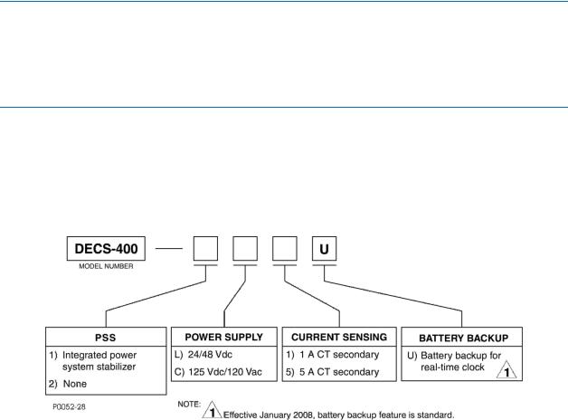
Model and Style Number ........................................................................................................................... |
7 |
Style Number ......................................................................................................................................... |
7 |
Human-Machine Interface .......................................................................................................................... |
9 |
Controls and Indicators.............................................................................................................................. |
9 |
Menu System........................................................................................................................................... |
10 |
Menu Navigation .................................................................................................................................. |
10 |
Menu Structure .................................................................................................................................... |
10 |
Editing Settings........................................................................................................................................ |
20 |
Screens with Special Editing Modes.................................................................................................... |
20 |
Password Protection................................................................................................................................ |
21 |
Metering Screen ...................................................................................................................................... |
22 |
Metering Values ................................................................................................................................... |
22 |
Setpoint................................................................................................................................................ |
23 |
Percent of Range................................................................................................................................. |
23 |
Alarms Message .................................................................................................................................. |
24 |
Operating Mode ................................................................................................................................... |
25 |
Functional Description ............................................................................................................................. |
27 |
DECS-400 Function Blocks..................................................................................................................... |
27 |
Analog Input Circuits............................................................................................................................ |
27 |
Front Panel Keyboard.......................................................................................................................... |
29 |
Contact Input Circuits .......................................................................................................................... |
29 |
Digital Signal Processor....................................................................................................................... |
30 |
Microprocessor .................................................................................................................................... |
30 |
IRIG Port .............................................................................................................................................. |
30 |
Memory Circuits ................................................................................................................................... |
31 |
DECS-400 |
Contents |

vi |
9369700990 Rev R |
Digital to Analog Converter.................................................................................................................. |
31 |
Control Output Circuits ........................................................................................................................ |
31 |
Meter Driver Circuits ............................................................................................................................ |
31 |
Relay Output Contacts......................................................................................................................... |
31 |
Front Panel LEDs................................................................................................................................. |
32 |
Front Panel LCD .................................................................................................................................. |
32 |
RS-232 Communication Port ............................................................................................................... |
32 |
RS-485 Communication Ports ............................................................................................................. |
32 |
Ethernet Port........................................................................................................................................ |
33 |
Modem ................................................................................................................................................. |
33 |
Power Supply....................................................................................................................................... |
33 |
Startup Functions .................................................................................................................................... |
33 |
Soft Start Function ............................................................................................................................... |
33 |
Field Flash/Buildup .............................................................................................................................. |
33 |
Failure to Build Up ............................................................................................................................... |
34 |
Voltage Matching ................................................................................................................................. |
34 |
Control Modes ......................................................................................................................................... |
34 |
AVR...................................................................................................................................................... |
35 |
Manual ................................................................................................................................................. |
35 |
Var ....................................................................................................................................................... |
35 |
PF ........................................................................................................................................................ |
36 |
Control Mode Pre-Position Setpoints................................................................................................... |
36 |
Transient Boost.................................................................................................................................... |
37 |
Protection Functions................................................................................................................................ |
37 |
Field Overcurrent ................................................................................................................................. |
37 |
Field Overvoltage................................................................................................................................. |
38 |
Generator Undervoltage ...................................................................................................................... |
38 |
Generator Overvoltage ........................................................................................................................ |
38 |
Loss of Sensing Voltage ...................................................................................................................... |
38 |
Loss of Field Isolation Transducer....................................................................................................... |
39 |
Generator Frequency Less Than 10 Hertz .......................................................................................... |
39 |
Power Supply Low ............................................................................................................................... |
39 |
Loss of Field (40Q) .............................................................................................................................. |
39 |
Field Overtemperature......................................................................................................................... |
40 |
Volts per Hertz (24).............................................................................................................................. |
40 |
Exciter Diode Monitor (EDM) ............................................................................................................... |
42 |
Voltage / Current Unbalance Detection ............................................................................................... |
43 |
Limiter Functions ..................................................................................................................................... |
43 |
Stator Current Limiter .......................................................................................................................... |
44 |
Overexcitation Limiter .......................................................................................................................... |
44 |
Underexcitation Limiter ........................................................................................................................ |
46 |
Underfrequency Limiter ....................................................................................................................... |
47 |
Volts per Hertz Limiter ......................................................................................................................... |
48 |
Var Limiter............................................................................................................................................ |
49 |
Limiter Scaling ..................................................................................................................................... |
49 |
Operation with Paralleled Generators ..................................................................................................... |
49 |
Droop Compensation........................................................................................................................... |
49 |
Reactive Differential............................................................................................................................. |
49 |
Line Drop Compensation ..................................................................................................................... |
49 |
Autotracking............................................................................................................................................. |
50 |
Between DECS-400 Operating Modes ................................................................................................ |
50 |
Between DECS-400 Units ................................................................................................................... |
50 |
Data Recording and Reporting................................................................................................................ |
50 |
Sequence of Events............................................................................................................................. |
50 |
Data Logging........................................................................................................................................ |
51 |
Trending............................................................................................................................................... |
52 |
Power System Stabilizer.......................................................................................................................... |
52 |
PSS Theory of Operation..................................................................................................................... |
53 |
Contents |
DECS-400 |

9369700990 Rev R |
vii |
Rate of Frequency Change Blocking................................................................................................... |
58 |
Field Isolation Module.............................................................................................................................. |
58 |
BESTCOMS™ Software ............................................................................................................................. |
59 |
Installation ............................................................................................................................................... |
59 |
Installing BESTCOMS ......................................................................................................................... |
59 |
Starting BESTCOMS ............................................................................................................................... |
59 |
The BESTCOMS Interface .................................................................................................................. |
59 |
Communication........................................................................................................................................ |
61 |
RS-232 Port Communication ............................................................................................................... |
61 |
Ethernet Port Communication.............................................................................................................. |
61 |
Modem Communication....................................................................................................................... |
63 |
Settings, Metering Values, and Data Records ........................................................................................ |
63 |
System Configuration .......................................................................................................................... |
63 |
Settings ................................................................................................................................................ |
71 |
Gain Settings ....................................................................................................................................... |
77 |
Limiters ................................................................................................................................................ |
81 |
Protection............................................................................................................................................. |
88 |
PSS...................................................................................................................................................... |
93 |
Metering ............................................................................................................................................... |
98 |
Data Log ............................................................................................................................................ |
102 |
Analysis.............................................................................................................................................. |
111 |
Logic .................................................................................................................................................. |
120 |
DECS-300 Settings File Converter........................................................................................................ |
120 |
Installation ............................................................................................................................................... |
121 |
Mounting................................................................................................................................................ |
121 |
DECS-400.......................................................................................................................................... |
121 |
Field Isolation Module........................................................................................................................ |
121 |
Isolation Power Transformer.............................................................................................................. |
121 |
Connections........................................................................................................................................... |
125 |
DECS-400 Terminations.................................................................................................................... |
125 |
Field Isolation Module Terminations .................................................................................................. |
127 |
DECS-400 Terminal Functions and Assignments ............................................................................. |
127 |
Field Isolation Module Terminal Functions and Assignments ........................................................... |
131 |
Cross-Current Compensation ............................................................................................................ |
132 |
Typical Interconnections .................................................................................................................... |
133 |
Communication Connections............................................................................................................. |
136 |
Commissioning ....................................................................................................................................... |
139 |
Preparation ............................................................................................................................................ |
139 |
Record System Parameters............................................................................................................... |
139 |
Testing and Evaluation.......................................................................................................................... |
139 |
Off-Line Tests—Turbine Not Spinning............................................................................................... |
139 |
Off-Line Tests—Turbine Spinning ..................................................................................................... |
142 |
Excitation Performance Evaluation.................................................................................................... |
145 |
Recommended PSS Testing ............................................................................................................. |
147 |
Maintenance ............................................................................................................................................ |
149 |
Storage .................................................................................................................................................. |
149 |
Warranty and Repair Service ................................................................................................................ |
149 |
Troubleshooting..................................................................................................................................... |
149 |
DECS-400 Appears Inoperative ........................................................................................................ |
149 |
Display Blank or Frozen..................................................................................................................... |
149 |
Generator Voltage Does Not Build .................................................................................................... |
149 |
Generator Voltage Builds but DECS-400 Fails To Flash................................................................... |
150 |
Field Voltage or Current Reading on LCD Does Not Change ........................................................... |
150 |
Low Generator Voltage (In AVR Mode)............................................................................................. |
150 |
High Generator Voltage (In AVR Mode) ............................................................................................ |
151 |
Generator Voltage Unstable (Hunting) .............................................................................................. |
151 |
DECS-400 |
Contents |

viii |
9369700990 Rev R |
Poor Voltage Regulation.................................................................................................................... |
151 |
No Buildup in FCR Mode ................................................................................................................... |
151 |
No Control Signal at Firing Circuit Input ............................................................................................ |
151 |
Limiters Do Not Limit at the Desired Level ........................................................................................ |
151 |
Poor Reactive Control........................................................................................................................ |
151 |
Protection or Limit Annunciation ........................................................................................................ |
151 |
Metering Readings Incorrect.............................................................................................................. |
151 |
No Communication ............................................................................................................................ |
151 |
Real-Time Clock Information Lost After Loss of Control Power ........................................................ |
151 |
DECS-400 Reboots Frequently ......................................................................................................... |
152 |
Backup Battery Replacement................................................................................................................ |
152 |
Upgrading DECS-400 Firmware............................................................................................................ |
152 |
Firmware Installation Procedure ........................................................................................................ |
153 |
Specifications.......................................................................................................................................... |
157 |
Operating Power.................................................................................................................................... |
157 |
AC Input (Style XCXX Only) .............................................................................................................. |
157 |
DC Input (Style XCXX, XLXX) ........................................................................................................... |
157 |
Generator Voltage Sensing ................................................................................................................... |
157 |
50 Hertz Sensing ............................................................................................................................... |
157 |
60 Hertz Sensing ............................................................................................................................... |
157 |
Bus Voltage Sensing ............................................................................................................................. |
157 |
50 Hertz Sensing ............................................................................................................................... |
157 |
60 Hertz Sensing ............................................................................................................................... |
157 |
Generator Current Sensing ................................................................................................................... |
158 |
Terminals ........................................................................................................................................... |
158 |
Field Voltage and Current ..................................................................................................................... |
158 |
Field Isolation Module............................................................................................................................ |
158 |
Electrical Specifications ..................................................................................................................... |
158 |
Physical Specifications ...................................................................................................................... |
158 |
Contact Inputs ....................................................................................................................................... |
158 |
Fixed Function Inputs ........................................................................................................................ |
158 |
Programmable Inputs ........................................................................................................................ |
159 |
Terminals ........................................................................................................................................... |
159 |
Accessory Input (Remote Setpoint Control) .......................................................................................... |
159 |
Voltage Input...................................................................................................................................... |
159 |
Current Input ...................................................................................................................................... |
159 |
Control Outputs ..................................................................................................................................... |
159 |
Voltage Control Output ...................................................................................................................... |
159 |
Current Control Output ...................................................................................................................... |
160 |
Metering Outputs ................................................................................................................................... |
160 |
Contact Outputs..................................................................................................................................... |
160 |
Dedicated Outputs ............................................................................................................................. |
160 |
Programmable Outputs...................................................................................................................... |
160 |
Contact Ratings ................................................................................................................................. |
160 |
Terminal Assignments ....................................................................................................................... |
160 |
Communication Ports ............................................................................................................................ |
160 |
Com 0 ................................................................................................................................................ |
160 |
Com 1 ................................................................................................................................................ |
161 |
Com 2 ................................................................................................................................................ |
161 |
Com 3 ................................................................................................................................................ |
161 |
J1 ....................................................................................................................................................... |
161 |
IRIG ....................................................................................................................................................... |
161 |
Regulation Accuracy.............................................................................................................................. |
161 |
AVR Mode.......................................................................................................................................... |
161 |
FCR and FVR Mode .......................................................................................................................... |
162 |
Var Control Mode............................................................................................................................... |
162 |
Power Factor Control Mode............................................................................................................... |
162 |
Metering Accuracy................................................................................................................................. |
162 |
Contents |
DECS-400 |
9369700990 Rev R |
ix |
Power System Stabilizer (PSS)............................................................................................................. |
162 |
Traverse Rates ...................................................................................................................................... |
162 |
Setpoint.............................................................................................................................................. |
162 |
Pre-Position Setpoint ......................................................................................................................... |
162 |
Setpoint Tracking................................................................................................................................... |
162 |
Delay.................................................................................................................................................. |
162 |
Traverse Rate .................................................................................................................................... |
163 |
Soft Start................................................................................................................................................ |
163 |
Soft Start Bias Level .......................................................................................................................... |
163 |
Soft Start Time Delay......................................................................................................................... |
163 |
Sequence of Events Recording............................................................................................................. |
163 |
Data Logging (Oscillography)................................................................................................................ |
163 |
Trending ................................................................................................................................................ |
163 |
Limiters .................................................................................................................................................. |
163 |
Underfrequency Compensation ......................................................................................................... |
163 |
Volts per Hertz ................................................................................................................................... |
163 |
Summing Point Overexcitation Limiter............................................................................................... |
164 |
Takeover Overexcitation Limiter ........................................................................................................ |
164 |
Underexcitation .................................................................................................................................. |
164 |
Stator Current .................................................................................................................................... |
165 |
Reactive Power.................................................................................................................................. |
165 |
Protection Functions.............................................................................................................................. |
165 |
Field Overvoltage............................................................................................................................... |
165 |
Field Overcurrent ............................................................................................................................... |
165 |
Generator Undervoltage .................................................................................................................... |
165 |
Generator Overvoltage ...................................................................................................................... |
165 |
Loss of Sensing Voltage .................................................................................................................... |
165 |
Generator Underfrequency ................................................................................................................ |
165 |
Loss of Field (40Q) ............................................................................................................................ |
165 |
Field Overtemperature....................................................................................................................... |
165 |
Volts per Hertz (24)............................................................................................................................ |
166 |
Exciter Diode Failure.......................................................................................................................... |
166 |
Type Tests............................................................................................................................................. |
166 |
Agency Certifications............................................................................................................................. |
166 |
UL ...................................................................................................................................................... |
166 |
CE ...................................................................................................................................................... |
166 |
GOST-R ............................................................................................................................................. |
166 |
NIIPT.................................................................................................................................................. |
166 |
Real-Time Clock Battery........................................................................................................................ |
166 |
Environment .......................................................................................................................................... |
167 |
Physical ................................................................................................................................................. |
167 |
Programmable Logic .............................................................................................................................. |
169 |
Logic Timer Configuration.................................................................................................................. |
169 |
Logic Schemes ...................................................................................................................................... |
170 |
Default Logic Scheme........................................................................................................................ |
170 |
Predefined Logic Schemes................................................................................................................ |
170 |
Logic Scheme Modification ................................................................................................................... |
184 |
Open “Single DECS-400 Without PSS” Logic Scheme for Editing.................................................... |
185 |
Delete Unneeded Logic Associations ................................................................................................ |
187 |
Create New Logic Associations ......................................................................................................... |
189 |
Verify and Finalize Modified Logic Scheme....................................................................................... |
192 |
Logic for Compound Machine Paralleling.............................................................................................. |
192 |
Logic Definitions .................................................................................................................................... |
195 |
Logic Inputs........................................................................................................................................ |
195 |
Outputs .............................................................................................................................................. |
198 |
Modbus™ Communication...................................................................................................................... |
203 |
DECS-400 Modbus™ Protocol............................................................................................................... |
203 |
DECS-400 |
Contents |

x |
9369700990 Rev R |
|
|
Message Structure ................................................................................................................................ |
203 |
|
Device Address Field......................................................................................................................... |
203 |
|
Function Code Field........................................................................................................................... |
204 |
|
Data Block Field................................................................................................................................. |
204 |
|
Error Check Field ............................................................................................................................... |
204 |
|
Modbus Modes of Operation ................................................................................................................. |
204 |
|
Serial Transmission Details................................................................................................................... |
204 |
|
Message Framing and Timing Considerations .................................................................................. |
205 |
|
Error Handling and Exception Responses......................................................................................... |
205 |
|
Communication Hardware Requirements ............................................................................................. |
206 |
|
RTU Communication Requirements .................................................................................................. |
206 |
|
TCP Communication Requirements .................................................................................................. |
206 |
|
Modbus™/TCP ....................................................................................................................................... |
206 |
|
Detailed Message Query and Response............................................................................................... |
206 |
|
Read Holding Registers..................................................................................................................... |
206 |
|
Preset Multiple Registers................................................................................................................... |
207 |
|
Preset Single Register (Write Single Holding Register) .................................................................... |
208 |
|
Response........................................................................................................................................... |
208 |
|
Loop Back Diagnostic Test (FC=8) with Diagnostic Sub Function, Return Query Data ................... |
209 |
|
Loop Back Diagnostic Test with Diagnostic Sub-Function, Restart Communications Option........... |
209 |
|
Loop Back Diagnostic Test with Diagnostic Sub-Function, Force Slave to Listen-Only Mode ......... |
209 |
|
Data Formats......................................................................................................................................... |
209 |
|
Generic Types UI8 and I8.................................................................................................................. |
210 |
|
Generic Types UI16 and I16.............................................................................................................. |
210 |
|
Generic Types UI32 and I32.............................................................................................................. |
210 |
|
Floating Point (R23_32) Data Format................................................................................................ |
211 |
|
CRC Error Check................................................................................................................................... |
211 |
|
DECS-400 Modbus™ Register Space ................................................................................................... |
212 |
|
DECS-400 Register Tables ................................................................................................................... |
213 |
|
Holding Registers for Version Data ................................................................................................... |
213 |
|
Holding Registers for Metering, Group 1 ........................................................................................... |
214 |
|
Holding Registers for System Configuration...................................................................................... |
216 |
|
Holding Registers for Operating Mode Parameters........................................................................... |
217 |
|
Holding Registers for Setpoint Parameters ....................................................................................... |
218 |
|
Holding Registers for Startup Parameters......................................................................................... |
220 |
|
Holding Registers for Limiter Parameters.......................................................................................... |
221 |
|
Holding Registers for Gain Parameters ............................................................................................. |
223 |
|
Holding Registers for Protection Function Parameters ..................................................................... |
224 |
|
Holding Registers for Exciter Diode Monitor Parameters.................................................................. |
225 |
|
Holding Registers for Relay Parameters ........................................................................................... |
225 |
|
Holding Registers for General ASCII and Modbus Communication Parameters .............................. |
226 |
|
Holding Registers for Metering Parameters, Group 2 ....................................................................... |
227 |
|
Holding Registers for Power System Stabilizer Parameters ............................................................. |
227 |
Revision History...................................................................................................................................... |
231 |
|
Contents |
DECS-400 |

9369700990 Rev R |
1 |
General Information
The DECS-400 Digital Excitation Control System is a microprocessor-based controller that offers excitation control, logic control, and optional power system stabilization in an integrated package. The DECS-400 controls field excitation by providing an analog signal used to control the firing (output) of an external power bridge. The DECS-400 monitors generator or motor parameters and acts to control, limit, and protect the machine from operating outside its capability.
The optional, onboard power system stabilizer is an IEEE-defined PSS2A, dual-input, “integral of accelerating power” stabilizer that provides supplementary damping for low-frequency, local mode and power system oscillations.
Integral programmable logic provides excitation system control and annunciation based on DECS-400 contact inputs, operating mode status, excitation system parameters, and user-defined programming. Setup and initial operation are facilitated by Basler Electric’s user-friendly BESTCOMS™ PC software that incorporates a test mode, flexible oscillography, and a graphic display of PSS test results.
The DECS-400 is designed for use with Basler Electric’s Interface Firing Module (IFM) and SSE or SSE-N power bridges. However, it will work equally well with any power bridge with a firing circuit that is compatible with the control signal output of the DECS-400.
Features
DECS-400 features and capabilities are listed below. The paragraphs following the list describe major DECS-400 features and functions in more detail.
•Five excitation control modes:
o Automatic Voltage Regulation (AVR)
o Field Current Regulation (FCR)
o Field Voltage Regulation (FVR)
o Power Factor (PF)
oVar
•Two pre-position setpoints (with adjustable traverse rate) for each excitation control mode
•Two PID groups
•Programmable analog control output selectable for 4 to 20 mAdc, –10 to +10 Vdc, or 0 to +10 Vdc
•Remote setpoint control input accepts analog voltage or current control signal
•Real-time metering
•Integrated power system stabilizer (PSS):
oGenerator or motor control modes, accommodates phase rotation changes between modes
o Speed and power sensing or speed-only sensing
oTwo-wattmeter or three-wattmeter methods of power measurement
•Soft start and voltage buildup control
•Five limiting functions:
oStator current
o |
Overexcitation |
o |
Underexcitation |
oUnderfrequency compensation
oReactive power
•Ten protection functions:
oField overvoltage
o Field overcurrent
DECS-400 |
General Information |

2 |
9369700990 Rev R |
oGenerator undervoltage
oGenerator overvoltage
oLoss of sensing voltage
oGenerator frequency less than 10 hertz
oLoss of field (40Q)
oField overtemperature
oVolts per hertz (24)
oExciter diode failure
•IRIG time synchronization
•Sixteen contact inputs:
oSix fixed-function inputs: AVR, Manual, Lower, Raise, Start, and Stop
oTen user-programmable inputs
•Eight contact outputs:
oTwo fixed-function outputs: Watchdog, On/Off
oSix user-programmable outputs, configurable for maintained, latched, or momentary operation
•Five communication ports:
oFront RS-232 port for interface with PC running BESTCOMS software
o Rear RS-485 port for dedicated communication with secondary, redundant DECS-400 o Rear RS-485 port using Modbus™ protocol for communication with remote terminal
o Rear RJ-11 jack connects to onboard modem that provides dial-in and dial-out capability
oRear RJ-45 jack provides Ethernet network communication
•Data logging, sequence of events recording, and trending
Generator Voltage Regulation
By utilizing digital signal processing and precise regulation algorithms, the DECS-400 regulates the generator rms voltage to within 0.2% of the setpoint from no-load to full-load.
Control Output
The DECS-400 supplies an isolated control output signal of 4 to 20 mAdc, 0 to 10 Vdc, or ±10 Vdc to the firing or control circuits of external power stages. The dc current produced by the power stages provides excitation to the field of the generator, motor, or exciter. The DECS-400 can control virtually any bridge that is capable of accepting these signals and is suitable for use on synchronous generators or motors.
Stability
PID (proportional + integral + derivative) stability control is utilized by the DECS-400. Preprogrammed stability (PID) settings are provided for both main field and exciter field applications. A suitable, standard stability set is available for most machines and applications. An additional, customizable setting group provides optimum generator transient performance. A PID selection/calculation program supplied with the DECS-400 assists in selecting the correct PID settings. Additional stability adjustments are provided for customizing the stability and transient performance of the minimum and maximum excitation limiters and the var/power factor controllers.
PID Setting Groups
The DECS-400 provides for two sets of PID settings to optimize performance under two distinct operating conditions, such as with a power system stabilizer (PSS) in or out of service. A fast controller provides optimum transient performance with the PSS in service, while a slower controller can provide improved damping of first swing oscillations with the PSS offline.
General Information |
DECS-400 |
9369700990 Rev R |
3 |
Power System Stabilizer (Style 1XXX)
An optional, integrated PSS duplicates the excellent performance of the Basler PSS-100 power system stabilizer without the complications of an additional control device. The PSS provides damping for local mode, inter-area, and inter-unit oscillations in the 0.1 to 5.0 hertz range. The PSS incorporated in the DECS-400 is a dual-input, IEEE type PSS2A stabilizer that utilizes the “integral of accelerating power” algorithm. The PSS can also be set up to respond only to frequency if required for unusual applications. Inputs required for PSS operation include three phase voltages and two or three phase line currents.
Underfrequency Limiter or Volts per Hertz Limiter
An underfrequency limiter or a V/Hz ratio limiter can be selected to avoid overfluxing the generator or other connected magnetic devices.
The underfrequency limiter slope can be set from 0 to 3 PU V/Hz in 0.1 hertz increments. The frequency roll-off knee-point can be set across a range of 15 to 90 hertz in 0.1 hertz increments.
The V/Hz ratio limiter regulates voltage based on a user-defined V/Hz slope that is adjustable between zero and 3.0 PU. The V/Hz ratio limiter includes two limiting levels to permit operation above the primary V/Hz range for a user-adjustable time limit to inhibit limiter response during transient frequency or voltage excursions.
Soft-Start Voltage Buildup
A user-adjustable voltage soft-start feature controls the rate of generator voltage buildup and prevents voltage overshoot during generator system startup. The soft-start feature is active in both AVR and Manual operating modes.
Reactive Droop and Line Drop Compensation
The DECS-400 has provisions for paralleling two or more generators by using reactive droop. Reactive differential compensation can be used with the addition of an external current transformer (CT) with a nominal secondary rating of 1 Aac or 5 Aac. The current input burden is less than 1 VA, so existing metering CTs can be used. A Line Drop Compensation setting allows the DECS-400 to compensate for line drop between parallel generators.
Setpoint Control
External adjustment of the active DECS-400 setpoint is possible through:
•Raise and lower contact inputs
•An auxiliary analog control input of 4 to 20 mAdc or ±10 Vdc
•A PC operating BESTCOMS software (provided with the DECS-400) and connected to the RS232 communication port
•A controller using Modbus™ protocol and connected to the RS-485 port
The traverse rates of all operating modes are independently adjustable, so the operator can customize the rate of adjustment and “feel” to meet his or her needs.
Dual Pre-Position Inputs
Two user-adjustable sets of predetermined operating points are provided for each mode of operation. At startup, and with the appropriate contact inputs applied to the DECS-400, the operating mode is driven to one of two preset operating or regulation levels (depending on the configuration of the system). An adjustable traverse rate setting can be used to control the rate at which the setpoint is driven toward the pre-position operating point. This feature allows the DECS-400 to be configured for multiple system and application needs.
Manual Operating Modes
The DECS-400 has two manual modes of operation: Field Current Regulation (FCR) and Field Voltage Regulation (FVR).
DECS-400 |
General Information |

4 |
9369700990 Rev R |
Field Current Regulation Mode
When operating in FCR mode, the DECS-400 regulates the dc output current of the power bridge. Because regulation of the field current is not dependent upon a generator voltage sensing input to the DECS-400, FCR mode can provide backup excitation control when a loss of sensing is detected. In FCR mode, as the generator load varies, the operator must manually vary the field current to maintain nominal generator voltage.
Field Voltage Regulation Mode
When operating in FVR mode, the DECS-400 regulates the dc output voltage of the power bridge. FVR enables the user to perform generator modeling and validation testing in accordance with WECC testing requirements for bus-fed (shunt type) excitation systems. FVR mode can also be used to smooth the transfer from the active exciter to a backup exciter.
Var/Power Factor Operating Mode
Var and Power Factor control modes are available when the generator is operating in parallel with the utility power grid. In Var control mode, the DECS-400 regulates the generator’s var output at a useradjustable setting. In Power Factor control mode, the DECS-400 regulates the generator’s var output to maintain a specific power factor as the kW load varies on the generator.
Overexcitation Limiters
Overexcitation limiters monitor the field current output of the voltage regulator or static exciter and act to limit the field current to prevent field overheating. The Overexcitation Limiter (OEL) function includes a cool-down feature to avoid damage to the rotor caused by repeated high forcing. The OEL is active in all modes except FCR mode. In FCR mode, limiter action is optional. The DECS-400 provides a choice of two types of overexcitation limiters: Summing Point and Takeover. The output of the Summing Point limiter is applied to the summing junction of the AVR control loop in addition to the AVR controller output. The output of the Takeover limiter overrides the normal AVR output.
Summing Point OEL
Three OEL current levels are defined for on-line operation: high, medium, and low. The generator can operate continuously at the low OEL current level and for programmed times at the medium and high OEL current levels. Two OEL current levels are defined for off-line (main breaker open) operation: high and low. The generator can operate continuously at the low OEL current level and for a programmed time at the high OEL current level.
Takeover OEL
The Takeover OEL determines the field current level at which limiting occurs by using an inverse time characteristic. Two current levels and a time dial setting are defined for the Takeover OEL. Separate curves may be selected for on-line and off-line operation. If the system enters an overexcitation condition, the field current is limited and made to follow the selected curve. Selection of on-line or off-line OEL levels and curves is determined by an OEL option selection.
Minimum Excitation Limiter
The Minimum Excitation Limiter prevents the excitation, being supplied to the generator field, from decreasing below safe operating levels. This prevents pole slip and possible machine damage. This action also limits the amount of vars being absorbed by the machine, based on user-defined settings. An internally-generated Underexcitation Limiting (UEL) curve based on a permissible var level at 0 kW can be utilized. Alternately, a five point UEL curve can be created to match specific generator characteristics. UEL action is optional in FCR mode.
Stator Current Limiter
The stator current limiter (SCL) senses the level of stator current and limits it to prevent stator overheating. The SCL operates in all modes except FCR and when the DECS-400 is off-line (52 J/K and
General Information |
DECS-400 |
9369700990 Rev R |
5 |
52 L/M contact inputs are closed). In FCR mode, the DECS-400 provides indication that a stator overcurrent condition exists, but limiter action is inhibited.
Two SCL current levels are provided: high and low. The generator can operate continuously at the low SCL level, but only for a programmed time at the high SCL level.
Reactive Power Limiter
The var limiter accommodates applications where the prime mover (turbine) has been uprated but the generator ratings are unchanged. In this case, the generator power factor is increased and the generator is var limited. The var limiter is available for these applications to limit reactive power flow out of the generator to a safe level.
Autotracking Between DECS-400 Operating Modes
The DECS-400 can provide autotracking (automatic following) of the controlling mode by the noncontrolling modes. This allows the operator to initiate a controlled, bumpless transfer of the DECS-400 between operating modes with minimal disturbance to the power system. This feature can be used in conjunction with a set of protective relays to initiate a transfer to a backup mode of operation (such as FCR mode) upon the detection of a system failure or fault (such as loss of sensing).
Autotracking Between DECS-400 Units
The DECS-400 is also designed to automatically track a second DECS-400 unit using dedicated communication ports on the two units. A backup DECS-400 controller can be placed in service and programmed to track the control output of the primary DECS-400. In the unlikely event of a failure of the first DECS-400, protective relays can initiate a transfer of control from the first to the second DECS-400 with minimal system disturbance.
Protective Functions
Protective functions built into the DECS-400 may be used as a backup to the primary protection relays and can be assigned to as many as six programmable output contacts via BESTCOMS software. The protective functions offer fully adjustable tripping levels and time delays. DECS-400 protective functions
are listed below. Functions marked with an asterisk ( ) have dual setting groups.
•Field overcurrent
•Field overtemperature
•Field overvoltage
•Generator overvoltage
•Generator undervoltage
•Loss of field
•Loss of Field Isolation Module
•Loss of sensing voltage
•Microprocessor watchdog
•Open exciter diode (brushless application)
•Shorted exciter diode (brushless application)
•Volts per hertz protection
Programmable Logic
The DECS-400 utilizes programmable logic functionality in the form of multiplexors, AND gates, OR gates, NOT gates, and timer gates. Inputs to the logic are in the form of discrete information including switching inputs, system status data, protection status data, limiter status data, alarm status data, and PSS status data. The outputs of the programmable logic module can be used to control the relay outputs as well as various other functions inside the DECS-400 such as control functions (start/stop, mode select, etc.), protection functions (Field Overvoltage Enable, Field Overcurrent Enable, etc.), limiter functions (OEL enable, UEL enable, etc.), and PSS functions. BESTCOMS provides a tool for customizing the system control logic for specific applications.
DECS-400 |
General Information |
6 |
9369700990 Rev R |
Metering
Two programmable, 4 to 20 mAdc, analog meter drivers are provided. The meter side is isolated from DECS-400 circuitry. Either driver can be programmed to meter a broad range of generator and system parameters.
Sequence of Events Recording
An integrated sequence of events recorder (SER) can be used to reconstruct the exact time of an event or disturbance. The DECS-400 monitors its contact inputs and outputs for changes of state, system operating changes, and alarm conditions. If any of these events occurs, the DECS-400 logs that event with a date and time stamp. The resulting event record allows the user to analyze a chain of events with accurate information regarding the sequence in which they occurred. Up to 127 events can be stored in DECS-400 volatile memory and those events are retrievable through BESTCOMS software.
Oscillography
The data recording feature can record up to six oscillographic records and store them in volatile memory. Up to six variables can be selected for monitoring. These variables include generator voltage, generator current (single-phase), frequency, kW, power factor, field voltage, and field current. Oscillographic records can be triggered through BESTCOMS or by a logic trigger or level trigger.
During commissioning, BESTCOMS can be used to trigger and save a record of a voltage step response. At the completion of commissioning, a logic trigger or level trigger can be used to activate the data recorder to capture the occurrence for review at a later time. DECS-400 alarms can also be used to start the data recorder. When an alarm condition occurs, an oscillographic record can be stored. A level trigger will initiate a record to be saved when a variable (such as field current) exceeds a predetermined setting. Oscillographic records are recorded in accordance with the IEEE Standard Common Format for Transient Data Exchange (COMTRADE) or log file format. Basler Electric provides BESTwave™, a COMTRADE viewer that enables viewing of oscillography records saved by the DECS-400.
Real-Time Monitoring
Real-time monitoring is possible for any of the parameters available for oscillography. The HMI real-time monitoring screen will display up to two parameters simultaneously. This data can be stored in a file for later reference.
Internal Testing Provisions
Using BESTCOMS, the user can configure and run both frequency and step response tests to facilitate commissioning or demonstrate system performance. The frequency response test has a frequency range of 0.1 to 10 hertz, and gain/phase information is generated in the form of a Bode plot. The DECS-400 also allows injection of test signals at various points in the PSS/voltage regulation loop for a high level of testing flexibility.
Communication
The DECS-400 is supplied with BESTCOMS software which makes DECS-400 programming and customization fast and easy. BESTCOMS includes a PID selection utility that provides a user-friendly format for selecting stability settings. BESTCOMS has monitoring screens for viewing all settings, metering screens for viewing all machine parameters, and control screens for remote control of the excitation system. A file converter within BESTCOMS enables conversion of DECS-300 settings files for use with the DECS-400.
An RS-485 port on the rear panel supports Modbus™ (floating point) communication protocol. Modbus™ is an open protocol, with all registers and operating instructions available in this instruction manual. This makes it simple for the user to develop custom communication software.
An Ethernet port on the rear panel enables communication with the DECS-400 over a TCP/IP network. Ethernet support in the DECS-400 enables remote access to DECS-400 settings and data through Modbus TCP or BESTCOMS. DECS-400 time synchronization with a network time server is also possible.
General Information |
DECS-400 |
9369700990 Rev R |
7 |
An internal modem is also provided to remotely access DECS-400 settings and alarms.
Password Protection
All DECS-400 parameters can be viewed at the front panel display, through BESTCOMS, or through Modbus™ without the need of a password. If the user wishes to change a setting, the proper password must be entered to allow access to the parameter. Two levels of password protection exist. One level provides global access to all parameters. The other level provides limited access to parameters normally associated with operator control.
Upgrading from DECS-300 to DECS-400
The upgrading process was designed to be easy, but some additional wiring may be necessary. An escutcheon plate for easy installation is recommended (see the Installation chapter). To make the upgrade process easier, BESTCOMS software for the DECS-400 provides a tool to convert a DECS-300 settings file to a DECS-400 settings file (see the BESTCOMS Software chapter).
Model and Style Number
DECS-400 electrical characteristics and operational features are defined by a combination of letters and numbers that make up the style number. The model number, together with the style number, describe the options included in a specific device and appear on a label affixed to the rear panel.
Style Number
The style number identification chart in Figure 1 defines the electrical characteristics and operational features available in the DECS-400.
Figure 1. DECS-400 Style Chart
DECS-400 |
General Information |

8 |
9369700990 Rev R |
General Information |
DECS-400 |

9369700990 Rev R |
9 |
Human-Machine Interface
This chapter describes the DECS-400 human-machine interface (HMI) and illustrates navigation of the menu tree accessed through the front panel and LCD.
Controls and Indicators
DECS-400 controls and indicators are illustrated in Figure 2 and described in Table 1. The locators and descriptions of Table 1 correspond to the locators shown in Figure 2.
|
|
Figure 2. Controls and Indicators |
|
|
Table 1. Control and Indicator Descriptions |
|
Locator |
Description |
|
A |
Null Balance Indicator. This LED lights when the setpoint of the inactive operating |
|
|
modes (AVR, FCR, Var, or Power Factor) match the setpoint of the active mode. |
|
B |
PSS Active Indicator. This LED lights when the integrated power system stabilizer is |
|
|
enabled and can generate a stabilizing signal in response to a power system |
|
|
disturbance. |
|
C |
Pre-Position Indicator. This LED lights when the setpoint of the active operating mode is |
|
|
at either of the two pre-position setting levels. |
|
D |
Lower Limit Indicator. This LED lights when the setpoint of the active operating mode is |
|
|
decreased to the lower setpoint limit. |
|
E |
Upper Limit Indicator. This LED lights when the setpoint of the active operating mode is |
|
|
increased to the upper setpoint limit. |
|
F |
Latch. Two lever-style latches (locators F and M) secure the DECS-400 draw-out |
|
|
assembly in its case. A captive Phillips screw in each latch can be tightened to lock the |
|
|
draw-out assembly in place. |
|
G |
Communication Port. This RS-232 port has a female DB-9 connector for local |
|
|
communication with a PC operating BESTCOMS software (supplied with the DECS- |
|
|
400). |
|
|
|
DECS-400 |
Human-Machine Interface |

10 |
9369700990 Rev R |
|
|
|
|
|
Locator |
Description |
|
H |
Reset Pushbutton. This button is pressed to reset DECS-400 alarms or cancel a |
|
|
settings editing session. |
|
I |
Scrolling Pushbuttons. These four buttons are used to scroll up, down, left, and right |
|
|
through the menu tree displayed on the front panel display (locator K). During an editing |
|
|
session, the left and right scrolling pushbuttons select the variable to be changed and |
|
|
the up and down scrolling pushbuttons change the value of the variable. |
|
J |
Edit Pushbutton. Pressing this button starts an editing session and enables changes to |
|
|
DECS-400 settings. When the Edit pushbutton is pressed to open an editing session, |
|
|
an LED on the button lights. At the conclusion of the editing session, the Edit |
|
|
pushbutton is pressed to save the setting changes and the LED turns off. |
|
K |
Display. The display consists of a 128 by 64 pixel, liquid crystal display (LCD) with LED |
|
|
backlighting. It serves as a local source of information provided by the DECS-400 and is |
|
|
used when programming settings through the front panel. The LCD displays operations, |
|
|
setpoints, loop gains, metering, protection functions, system parameters, and general |
|
|
settings. |
|
L |
Identification Label. The identification label contains information such as the model, |
|
|
style, and serial numbers and operating power and sensing current ratings. |
|
M |
Latch. Two lever-style latches (locators F and M) secure the DECS-400 draw-out |
|
|
assembly in its case. A captive Phillips screw in each latch can be tightened to lock the |
|
|
draw-out assembly in place. |
Menu System
The front panel menu system consists of a network of screens that enable the user to edit DECS-400 settings and view system parameters.
Menu Navigation
Movement through the front panel menu system is achieved by pressing the four, front-panel scrolling pushbuttons (locator I in Figure 2).
Navigation aids assist the user in moving from screen to screen and are provided at the top and bottom lines of each screen.
The top line of each screen contains the menu path which is similar to the path of a file on a PC. When the menu path exceeds the width of the LCD, the first part of the menu path is replaced with two periods (..) so that the last part of the path remains visible.
The bottom line indicates which menu screens can be accessed from the current screen by using the left, lower, or right scrolling pushbuttons. The screens accessed by the left, lower, and right scrolling pushbuttons are indicated by a <, v, and > symbol followed by an abbreviated menu name.
The front panel Reset pushbutton (locator H in Figure 2) provides a shortcut to the metering screen when a settings editing session is not in progress.
Menu Structure
The front panel menu system has nine branches:
1.Operating. Start/stop, mode, and pre-position setpoint status.
2.Setpoints. Mode setting values such as AVR, FCR, droop, var, and power factor.
3.Loop Gains. PID settings.
4.Metering. Real-time metering of user-selected parameters and alarm messages.
5.Protection. Protective Function setting parameters.
Human-Machine Interface |
DECS-400 |

9369700990 Rev R |
11 |
6.Limiters. System limiters such as overexcitation and underexcitation.
7.PSS. The power system stabilizer menu consists of four sub-menus which include Control, Parameters, Limiters, and Configuration.
8.System Parameters. The system parameters menu consists of nine sub-menus which include Generator Data, Field Data, Transformers, Configuration, Output Contacts, Traverse Rates, Preposition Modes, Startup, and Tracking.
9.General Settings. The general settings menu consists of three sub-menus which include Communications, LCD Contrast, and Real-Time Clock.
From the DECS-400 title screen, the Operating menu branch is accessed first by pressing the Down pushbutton. Then, the remaining branches are accessed by pressing the left or right scrolling pushbuttons.
A detailed list of the menu system screens is provided below. The menu paths appear on the left and the settings appear on the right.
\D400\OPER |
OPERATING |
\OPERATE_1 |
START/STOP |
AVR/MANUAL |
|
PF OR VAR |
|
FCR OR FVR |
|
PREPOSN 1 |
|
PREPOSN 2 |
|
\OPERATE_2 |
VOLT MATCH |
INT TRACK |
|
EXT TRACK |
|
CROSS CURNT |
|
LINE DROP |
|
DROOP |
|
\OPERATE_3 |
INNER LP |
\D400\SETPT |
SETPOINTS |
\MODE_SET1 |
AVR MODE |
FCR MODE |
|
DROOP |
|
VAR MODE |
|
PF MODE |
|
FVR MODE |
|
\MODE1\RANGE_1 |
FINE V BD |
AVR MIN |
|
AVR MAX |
|
FCR MIN |
|
FCR MAX |
|
KW LVL TRNS |
|
\MODE1\RANGE_2 |
MIN VAR OUT |
MAX VARA OUT |
|
MAX LAG PF |
|
MAX LEAD PF |
|
FVR MIN |
|
FVR MAX |
|
\MODE1\RANGE_3 |
V MATCH BD |
V MATCH REF |
|
\MODE_SET2 |
LINE DROP |
\PREP_SET1 |
AVR MODE |
FCR MODE
VAR MODE
DECS-400 Human-Machine Interface

12 |
9369700990 Rev R |
PF MODE |
|
FVR MODE |
|
\PREP_SET2 |
AVR MODE |
FCR MODE |
|
VAR MODE |
|
PF MODE |
|
FVR MODE |
|
\D400\GAIN |
LOOP GAINS |
\P_AVR_GAINS |
PRI STB RG |
AVR Kp |
|
AVR Ki |
|
AVR Kd |
|
AVR Td |
|
AVR Kg |
|
\AVRG1\S_AVR_GAINS |
SEC STB RG |
AVR Kp |
|
AVR Ki |
|
AVR Kd |
|
AVR Td |
|
AVR Kg |
|
\P_FCR_GAINS |
FCR Kp |
FCR Ki |
|
FCR Kd |
|
FCR Td |
|
FCR Kg |
|
\P_FVR_GAINS |
FVR Kp |
FVR Ki |
|
FVR Kd |
|
FVR Td |
|
FVR Kg |
|
\LIM_GAINS |
OEL Ki |
OEL Kg |
|
UEL Ki |
|
UEL Kg |
|
SCL Ki |
|
SCL Kg |
|
\LIMGN\\LIM_GAINS2 |
VARL Ki |
VARL Kg |
|
\CTL_GAINS |
PF Ki |
PF Kg |
|
VAR Ki |
|
VAR Kg |
|
V MATCH Kg |
|
\IN_LP_GAINS |
INNER LP Ki |
INNER LP Kg |
|
\D400_METERING |
METERING |
See Metering Screen, Metering Values for a list of the parameters available for display.
\D400_PROT |
PROTECTION |
\V/HZ_PROT1 |
V/HZ ENABLE |
V/HZ PCKUP |
|
TIME DIAL |
|
RESET DIAL |
|
DLAY1 PKUP |
|
DLAY1 TIME |
|
Human-Machine Interface |
DECS-400 |
9369700990 Rev R |
13 |
|
|
\V/HZ_PROT2 |
DLAY2 PKUP |
DLAY2 TIME |
|
CURVE EXP |
|
\PROT_ENAB1 |
FIELD OV |
FIELD OC |
|
STATOR OV |
|
STATOR UV |
|
NO SENSING |
|
NO SNS->MAN |
|
\ENAB1\S_PROT_ENE |
FIELD OV |
FIELD OC |
|
STATOR OV |
|
STATOR UV |
|
FIELD OT |
|
LOSS FIELD |
|
\PROT_ENAB2 |
FIELD OT |
LOSS FIELD |
|
FIT FAILED |
|
POWER LOW |
|
EX DIOD OD |
|
EX DIOD SD |
|
\P_PROT_LVL1 |
FIELD OV |
FIELD OC |
|
STATOR OV |
|
STATOR UV |
|
FIELD OT |
|
LOS BAL V |
|
\P_PROT_LVL1 |
FIELD OV |
FIELD OC |
|
STATOR OV |
|
STATOR UV |
|
FIELD OT |
|
LOSS FIELD |
|
\P_PROT_LVL2 |
LOS IMBAL V |
LOSS FIELD |
|
EDM OD RPL |
|
EDM SD RPL |
|
EDM INH LVL |
|
\P_PROT_TMR1 |
FIELD OV |
FIELD OC TD |
|
STATOR OV |
|
STATOR UV |
|
NO SENSING |
|
FIELD OT |
|
\P_TM1\S_PROT_TMR1 |
FIELD OV |
FIELD OC TD |
|
STATOR OV |
|
STATOR UV |
|
FIELD OT |
|
LOSS FIELD |
|
\P_PROT_TMR2 |
LOSS FIELD |
FIT FAILED |
|
EX DIOD OD |
|
EX DIOD SD |
|
DECS-400 |
Human-Machine Interface |
14 |
9369700990 Rev R |
\D400\LIMIT |
LIMITERS |
\OPTION_1 |
OEL STYLE |
OEL OPTION |
|
UEL STYLE |
|
OEL GROUP |
|
UEL GROUP |
|
SCL GROUP |
|
\OPTION_2 |
UF OR V/HZ |
OEL ENABLE |
|
UEL ENABLE |
|
SCL ENABLE |
|
UEL FLTR TC |
|
UEL VOL EXP |
|
\P_ONLINE |
INST LIMIT |
INST TIME |
|
MED LIMIT |
|
MED TIME |
|
CONT LIMIT |
|
\P_ONL\S_ONLINE |
INST LIMIT |
INST TIME |
|
MED LIMIT |
|
MED TIME |
|
CONT LIMIT |
|
\P_OFFLINE |
OEL HI LIM |
HI LIM TIME |
|
OEL LO LIM |
|
\P_OFL\S_OFFLINE |
OEL HI LIM |
HI LIM TIME |
|
OEL LO LIM |
|
\P_OFFTAKOVR |
OEL MAX CUR |
OEL MIN CUR |
|
OEL TD |
|
\P_OFT\S_OFFTAKOVR |
OEL MAX CUR |
OEL MIN CUR |
|
OEL TD |
|
\P_ONTAKOVR |
OEL MAX CUR |
OEL MIN CUR |
|
OEL TD |
|
\P_ONT\S_ONTAKOVR |
OEL MAX CUR |
OEL MIN CUR |
|
OEL TD |
|
\P_UEL_CRV_X |
PNT 1 WATTS |
PNT 2 WATTS |
|
PNT 3 WATTS |
|
PNT 4 WATTS |
|
PNT 5 WATTS |
|
\P_UEX\S_UEL_CRV_X |
PNT 1 WATTS |
PNT 2 WATTS |
|
PNT 3 WATTS |
|
PNT 4 WATTS |
|
PNT 5 WATTS |
|
\P_UEL_CRV_Y |
PNT 1 VARS |
PNT 2 VARS |
|
PNT 3 VARS |
|
PNT 4 VARS |
|
PNT 5 VARS |
|
|
|
Human-Machine Interface |
DECS-400 |
9369700990 Rev R |
15 |
|
|
\S_UEL_CRV_Y |
PNT 1 VARS |
PNT 2 VARS |
|
PNT 3 VARS |
|
PNT 4 VARS |
|
PNT 5 VARS |
|
\P_SCLIM |
SCL HI LIM |
HI LIM TIME |
|
SCL LO LIM |
|
INIT DELAY |
|
\P_SCL\S_SCLIM |
SCL HI LIM |
HI LIM TIME |
|
SCL LO LIM |
|
INIT DELAY |
|
\VARLM |
VARL ENABLE |
PRI SETPOINT |
|
PRI INITDLY |
|
SEC SETPNT |
|
SEC INITDLY |
|
VARL GROUP |
|
\UF_V/HZ |
CORNER FREQ |
UF SLOPE |
|
V/HZ HI |
|
V/HZ LO |
|
V/HZ TIME |
|
\D400\PSS |
POWER SYSTEM STABILIZER |
\CONTROL |
PSS CONTROL |
\P_BASIC_CTL |
SETTING GRP |
TM PWRN TLD |
|
TM PWR HYST |
|
\P_CTL\S_BASIC_CTL |
SECONDARY |
TM PWRN TLD |
|
TM PWR HYST |
|
\P_SOFT_SW1 |
SSW 0 |
SSW 1 |
|
SSW 2 |
|
SSW 3 |
|
SSW 4 |
|
SSW 5 |
|
\P_SS1\S_SOFT_SW2 |
SSW 0 |
SSW 1 |
|
SSW 2 |
|
SSW 3 |
|
SSW 4 |
|
SSW 5 |
|
\P_SOFT_SW2 |
SSW 6 |
SSW 7 |
|
SSW 8 |
|
SSW 9 |
|
SSW 10 |
|
\P_SS2\S_SOFT_SW2 |
SSW 6 |
SSW 7 |
|
SSW 8 |
|
SSW 9 |
|
SSW 10 |
|
DECS-400 |
Human-Machine Interface |
16 |
9369700990 Rev R |
|
|
\D400\PSS\PARAMETER |
PSS PARAMETERS |
\P_FILTER1 |
QUADTURE XQ |
SCALER KPE |
|
LP FLTR T11 |
|
LP FLTR T12 |
|
LP FLTR T13 |
|
RT FLTR TR |
|
\P_FTR\S_FILTER |
QUADTURE XQ |
SCALER KPE |
|
LP FLTR T11 |
|
LP FLTR T12 |
|
LP FLTR T13 |
|
RT FLTR TR |
|
\P_FILTER2 |
HP FLTR H |
HP FLTR TW1 |
|
HP FLTR TW2 |
|
HP FLTR TW3 |
|
HP FLTR TW4 |
|
\P_FTR\S_FILTER2 |
HP FLTR H |
HP FLTR TW1 |
|
HP FLTR TW2 |
|
HP FLTR TW3 |
|
HP FLTR TW4 |
|
\P_FILTER3 |
NUM EXP N |
NUM EXP M |
|
\P_FTR\S_FILTER3 |
SECONDARY FILTER 3 |
NUM EXP N |
|
NUM EXP M |
|
\P_TRSN_FLTR |
FILTER 1 ZN |
FILTER 1 ZD |
|
FILTER 1 WN |
|
FILTER 2 ZN |
|
FILTER 2 ZD |
|
FILTER 2 WN |
|
\P_TSN\S_TRSN_FLTR |
FILTER 1 ZN |
FILTER 1 ZD |
|
FILTER 1 WN |
|
FILTER 2 ZN |
|
FILTER 2 ZD |
|
FILTER 2 WN |
|
\P_PHSE_COMP1 |
PHASE 1 TLD |
PHASE 1 TLG |
|
PHASE 2 TLD |
|
PHASE 2 TLG |
|
\S_PHSE_COMP1 |
PHASE 1 TLD |
PHASE 1 TLG |
|
PHASE 2 TLD |
|
PHASE 2 TLG |
|
\P_PHSE_COMP2 |
PHASE 3 TLD |
PHASE 3 TLG |
|
PHASE 4 TLD |
|
PHASE 4 TLG |
|
\S_PHSE_COMP2 |
PHASE 3 TLD |
PHASE 3 TLG |
|
PHASE 4 TLD |
|
PHASE 4 TLG |
|
|
|
Human-Machine Interface |
DECS-400 |
9369700990 Rev R |
17 |
|
|
\D400\PSS\LIMTERS |
PSS LIMITERS |
\P_OUTPUT_LMT |
UPPER LIMIT |
LOWER LIMIT |
|
GAIN |
|
\S_OUTPUT_LMT |
UPPER LIMIT |
LOWER LIMIT |
|
GAIN |
|
\P_VOLT_LIMIT |
TIME CONST |
SETPOINT |
|
\P_VLT\S_VOLT_LMT |
TIME CONST |
SETPOINT |
|
\P_LOGIC_LMT |
FLTR NRM TM |
FLTR LMT TM |
|
OUT UPR LMT |
|
OUT LWR LMT |
|
OUT TM DLY |
|
\P_LOG\S_LOGIC_LMT |
FLTR NRM TM |
FLTR LMT TM |
|
OUT UPR LMT |
|
OUT LWR LMT |
|
OUT TM DLY |
|
\D400\PSS\CONFIG |
PSS CONFIGURATION |
\CNFG SET GP |
SETTING GROUP CONFIGURATION |
PWR TLD ENA |
|
SG PWR TLD |
|
ST PWR HYST |
|
\PSS_ROC |
ROC ENABLE |
ROC THRESH |
|
ROC TM DLY |
|
ROC BLKTIM |
|
ROC LPF TC |
|
ROC WF TC |
|
\D400\SYSTEM |
SYSTEM PARAMETERS |
\GENERATOR |
GENERATOR DATA |
\GEN\GEN_DATA |
RATED VOLT |
FREQUENCY |
|
RATED KVA |
|
\FIELD_DATA |
FIELD DATA |
\FIELD_DATA1 |
FIELD VOLT |
FIELD CURR |
|
SHUNT RATING |
|
ISOL BOX IN |
|
FIELD RES |
|
AMB TEMP |
|
\FIELD_DATA_2 |
BRUSH DROP |
POLE RATIO |
|
\TRNSFRMRS |
TRANSFORMERS |
\XFMRS\XFMR_DATA |
GEN PT PRI |
GEN PT SEC |
|
BUS PT PRI |
|
BUS PT SEC |
|
GEN CT PRI |
|
GEN CT SEC |
|
DECS-400 |
Human-Machine Interface |
18 |
9369700990 Rev R |
|
|
\CONFIGURE |
CONFIGURATION |
\CONFG\CNFG_DATA_1 |
FIELD TYPE |
VLTAGE SNSE |
|
MOTOR MODE |
|
CURRNT SNSE |
|
CT SELECT |
|
\CNFG\CNFG_DATA_2 |
CTRL SIGNAL |
AUX IN TYPE |
|
AUX IN FCTN |
|
CRSS I GAIN |
|
TEMP MODE |
|
\AUX_GAINS |
AVR MODE |
FCR MODE |
|
VAR MODE |
|
PF MODE |
|
FVR MODE |
|
INNER/OUTER |
|
\CONTACTS |
OUTPUT CONTACTS |
\CNTCT\RELAY_1 |
OUTPT SENSE |
OUTPUT TYPE |
|
MOMENT TIME |
|
\CNTCT\RELAY_2 |
OUTPT SENSE |
OUTPUT TYPE |
|
MOMENT TIME |
|
\CNTCT\RELAY_3 |
OUTPT SENSE |
OUTPUT TYPE |
|
MOMENT TIME |
|
\CNTCT\RELAY_4 |
OUTPT SENSE |
OUTPT TYPE |
|
MOMENT TIME |
|
\CNTCT\RELAY_5 |
OUTPT SENSE |
OUTPT TYPE |
|
MOMENT TIME |
|
\CNTCT\RELAY_6 |
OUTPT SENSE |
OUTPT TYPE |
|
MOMENT TIME |
|
\TRVRS_HEAD |
TRAVERSE RATES |
\TRVRS\TRVRS_RATE |
AVR MODE |
FCR MODE |
|
VAR MODE |
|
PF MODE |
|
FVR MODE |
|
\PMODE_HEAD |
PRE-POSITION MODES |
\PMODE\PREP_MODE1 |
AVR MODE |
FCR MODE |
|
VAR MODE |
|
PF MODE |
|
FVR MODE |
|
\PREP1_RATES1 |
AVR TRAVEL |
AVR RATE |
|
FCR TRAVEL |
|
FCR RATE |
|
VAR TRAVEL |
|
VAR RATE |
|
\PREP1_RATES2 |
PF TRAVEL |
PF RATE |
|
|
|
Human-Machine Interface |
DECS-400 |
Loading...