


DECS-250N
Table of contents
 Loading...
INSTRUCTION MANUA L
FOR
DECS-250N
Digital Excitation Control System
Publication: 9440500990
Revision: D May-15


9440500990 Rev D i
Caution
Note
Note
Be sure that the device is hard-wired to earth groun d with no smaller
with local codes and conventions.
Preface
This instruction manual provides information about the installation and operation of the DECS-250N
Digital Excitation Control System. To accomplish this, the following information is provided:
• General Information
• Human-machine interface
• Functional description
• Installation
• BESTCOMSPlus
• Setup
• Communication protocols
• Maintenance
• Specifications
• Expansion modules
Conventions Used in this Ma nua l
Important safety and procedural information is emphasized and presented in this manual through
warning, caution, and note boxes. Each type is illustrated and defined as follows.
®
software
Warning!
Warning boxes call attention to conditions or actions that may cause
personal injury or death.
Caution boxes call attention to operating conditions that may lead to
equipment or property damage.
Note boxes emphasize important information pertaining to installation
or operation.
than 12 AWG (3.3 mm2) copper wire attached to the case ground
terminal. When the device is configured in a system with other
devices, a separate lead should be connected from the ground bus to
each device.
Current transformer (CT) grounding should be applied in accordance
DECS-250N Preface

ii 9440500990 Rev D
Basler Electric does not assume any responsibility to compliance or noncompliance with national code, local code,
For terms of service relating to this product and software, see the Commercial Terms of Products and Services
document available at www.basler.com/terms.
This publication contains confidential information of Basler Electric Company, an Illinois corporation. It is loaned for
and options are subject to modification without notice. Over time, improvements and revisions may be made to this
manual.
The English-language version of this manual serves as the only approved manual version.
12570 State Route 143
Highland IL 62249-1074 USA
www.basler.com
info@basler.com
Tel: +1 618.654.2341
Fax: +1 618.654.2351
© 2015 by Basler Electric
All rights reserved
First printing: October 2012
Warning!
READ THIS MANUAL. Read this manual before installing, operating, or maintaining the DECS-250N.
Note all warnings, cautions, and notes in this manual as well as on the product. Keep this manual with
the product for reference. Only qualified personnel should install, operate, or service this system.
Failure to follow warning and cautionary labels may result in personal injury or property damage.
Exercise caution at all times.
or any other applicable code. This manual serves as reference material that must be well understood prior to
installation, operation, or maintenance.
confidential use, subject to return on request, and with the mutual understanding that it will not be used in any
manner detrimental to the interests of Basler Electric Company and used strictly for the purpose intended.
It is not the intention of this manual to cover all details and variations in equipment, nor does this manual provide
data for every possible contingency regarding installation or operation. The availability and design of all features
publication. Before performing any of the following procedures, contact Basler Electric for the latest revision of this
Preface DECS-250N

9440500990 Rev D iii
This product contains, in part, open source softw are (software licensed in a way that ensures freedom to run,
copy, distribute, study, change, and improve the software) and you are granted a license to that software under the
formation is provided above). A fee of no more than our cost of physically performing the source code distribution
Portions of this software are copyright © 2014 The Free Type Project (www.freetype.org). All rights reserved.
terms of either the GNU General Public License or GNU Lesser General Public License. The licenses, at the time
of sale of the product, allow you to freely copy, modify, and redistribute that software and no other statement or
documentation from us, including our End User License Agreement, places any additional restrictions on what you
may do with that software.
For at least three (3) years from the date of distribution of this product, a machine-readable copy of the complete
corresponding source code for the version of the programs distributed to you will be sent upon request (contact
in
is charged.
The source code is distributed in the hope that it will be useful, but WITHOUT ANY REPRESENTATION or
WARRANTY or even the implied warranty of MERCHANTABILITY or FITNESS FOR A PARTICULAR PURPOSE.
Refer to the source code distribution for additional restrictions regarding warranty and copyrights.
For a complete copy of GNU GENERAL PUBLIC LICENSE Version 2, June 1991 or GNU LESSER GENERAL
PUBLIC LICENSE Version 2.1, February 1999 refer to www.gnu.org or contact Basler Electric. You, as a Basler
Electric Company customer, agree to abide by the terms and conditions of GNU GENERAL PUBLIC LICENSE
Version 2, June 1991 or GNU LESSER GENERAL PUBLIC LICENSE Version 2.1, February 1999, and as such
hold Basler Electric Company harmless related to any open source software incorporated in this product. Basler
Electric Company disclaims any and all liability associated with the open source software an d the user agr ees to
defend and indemnify Basler Electric Company, its directors, officers, and employees from and against any and all
losses, claims, attorneys' fees, and expenses arising from the use, sharing, or redistribution of the software.
Review the software website for the latest version of the software documentation.
DECS-250N Preface

iv 9440500990 Rev D
Revision History DECS-250N

9440500990 Rev D v
Contents
Introduction ................................................................................................................................................. 1
Features and Functions ............................................................................................................................. 1
Applications ............................................................................................................................................... 2
Package ..................................................................................................................................................... 2
Optional Features and Capabilities ........................................................................................................... 2
Style Number ......................................................................................................................................... 3
Storage ...................................................................................................................................................... 3
Electrolytic Capacitor Considerations .................................................................................................... 3
Controls and Indicators .............................................................................................................................. 5
Front Panel Illustration and Description .................................................................................................... 5
Menu Navigation ........................................................................................................................................ 6
Adjusting Settings ...................................................................................................................................... 7
Display Setup ............................................................................................................................................ 7
LCD ........................................................................................................................................................ 7
Sleep Mode ............................................................................................................................................ 7
Language ............................................................................................................................................... 7
Screen Scrolling ..................................................................................................................................... 8
Power Inputs ................................................................................................................................................ 9
Control Power ............................................................................................................................................ 9
Operating Power ........................................................................................................................................ 9
Power Stage ............................................................................................................................................... 11
Field Transient Protection........................................................................................................................ 11
Inverting Style Excitation System Compatibility ...................................................................................... 11
Voltage and Current Sensing ................................................................................................................... 13
Generator Voltage ................................................................................................................................... 13
Generator Current ................................................................................................................................... 13
Phase Sensing ..................................................................................................................................... 13
Cross-Current Compensation .............................................................................................................. 14
Bus Voltage ............................................................................................................................................. 15
Synchronizer ............................................................................................................................................. 17
Generator Synchronizat ion ...................................................................................................................... 17
Frequency Correction .......................................................................................................................... 17
Voltage Correction ............................................................................................................................... 17
Angle Compensation ........................................................................................................................... 18
Failure of Synchronization ................................................................................................................... 18
Voltage Matching ..................................................................................................................................... 19
Breaker Hardware Configuration ............................................................................................................. 19
Breaker Failure .................................................................................................................................... 19
Generator Breaker ............................................................................................................................... 19
Generator and Bus Condition Detection.................................................................................................. 20
Generator Condition............................................................................................................................. 21
Generator Stability ............................................................................................................................... 21
Bus Condition ....................................................................................................................................... 21
Bus Stability ......................................................................................................................................... 21
Generator Governor Control .................................................................................................................... 23
Regulation .................................................................................................................................................. 25
Regulation Modes .................................................................................................................................... 25
AVR ...................................................................................................................................................... 25
FCR ...................................................................................................................................................... 25
FVR ...................................................................................................................................................... 25
Var ....................................................................................................................................................... 26
DECS-250N Contents

vi 9440500990 Rev D
Power Factor ........................................................................................................................................ 27
Pre-Position Setpoints ............................................................................................................................. 27
Transient Boost ....................................................................................................................................... 28
Operation with Paralleled Generators ..................................................................................................... 29
Reactive Droop Compensation ............................................................................................................ 29
Cross-Current Compensation .............................................................................................................. 29
Network Load Sharing ......................................................................................................................... 29
Line Drop Compensation ..................................................................................................................... 30
Autotracking ............................................................................................................................................. 31
Internal Setpoint Tracking .................................................................................................................... 31
External Setpoint Tracking ................................................................................................................... 32
Setpoint Configure ................................................................................................................................... 32
Auxiliary Control ....................................................................................................................................... 33
Auxiliary Control Input Type .................................................................................................................... 33
Auxiliary Control Input Function .............................................................................................................. 33
PSS Test Input ..................................................................................................................................... 33
Limiter Scaling ..................................................................................................................................... 33
Setpoint Limits ..................................................................................................................................... 33
Auxiliary Control Gains ............................................................................................................................ 33
AVR Mode ............................................................................................................................................ 34
FCR Mode ............................................................................................................................................ 34
FVR Mode ............................................................................................................................................ 34
Var Mode ............................................................................................................................................. 34
Power Factor Mode.............................................................................................................................. 34
Summing Type ........................................................................................................................................ 34
Contact Inputs and Outputs ..................................................................................................................... 37
Contact Inputs ......................................................................................................................................... 37
Start and Stop Inputs ........................................................................................................................... 37
Programmable Inputs .......................................................................................................................... 37
Contact Outputs ....................................................................................................................................... 38
Watchdog Output ................................................................................................................................. 38
Programmable Outputs ........................................................................................................................ 38
Protection................................................................................................................................................... 41
Voltage Protection ................................................................................................................................... 41
Overexcitation (Volts per Hertz) ........................................................................................................... 41
Generator Undervoltage ...................................................................................................................... 43
Generator Overvoltage ........................................................................................................................ 44
Loss of Sensing ................................................................................................................................... 44
Frequency Protection .............................................................................................................................. 45
Overfrequency ..................................................................................................................................... 45
Underfrequency ................................................................................................................................... 45
Power Protection ..................................................................................................................................... 46
Reverse Power .................................................................................................................................... 46
Loss of Excitation ................................................................................................................................. 46
Field Protection ........................................................................................................................................ 48
Field Overvoltage ................................................................................................................................. 48
Field Overcurrent ................................................................................................................................. 48
Exciter Diode Monitor .......................................................................................................................... 50
Power Input Failure .............................................................................................................................. 52
Sync-Check Protection ............................................................................................................................ 53
Generator Frequency Less Than 10 Hertz .............................................................................................. 54
Configurable Protection ........................................................................................................................... 54
Limiters ...................................................................................................................................................... 57
Overexcitation Limiter .............................................................................................................................. 57
Summing Point OEL ............................................................................................................................ 57
Takeover OEL ...................................................................................................................................... 58
Contents DECS-250N

9440500990 Rev D vii
Underexcitation Limiter ............................................................................................................................ 61
Stator Current Limiter .............................................................................................................................. 63
Low-Level Limiting ............................................................................................................................... 64
High-Level Limiting .............................................................................................................................. 64
Initial Delay .......................................................................................................................................... 64
Var Limiter ............................................................................................................................................... 65
Limiter Scaling ......................................................................................................................................... 65
Underfrequency Limiter ........................................................................................................................... 66
Volts per Hertz ..................................................................................................................................... 67
Metering ..................................................................................................................................................... 69
Metering Explorer .................................................................................................................................... 69
HMI ...................................................................................................................................................... 69
BESTCOMSPlus® ................................................................................................................................ 69
Metered Parameters ................................................................................................................................ 70
Generator ............................................................................................................................................. 70
Power ................................................................................................................................................... 70
Bus ....................................................................................................................................................... 71
Field ..................................................................................................................................................... 72
PSS ...................................................................................................................................................... 72
Synchronization ................................................................................................................................... 73
Auxiliary Control Input .......................................................................................................................... 73
Tracking ............................................................................................................................................... 73
Control Panel ....................................................................................................................................... 74
Metering Summary............................................................................................................................... 75
Status Indication ...................................................................................................................................... 76
System Status ...................................................................................................................................... 76
Inputs ................................................................................................................................................... 77
Outputs ................................................................................................................................................ 78
Network Load Share ............................................................................................................................ 79
Configurable Protection ....................................................................................................................... 79
Alarms .................................................................................................................................................. 80
Real-Time Clock .................................................................................................................................. 83
Auto Export Metering ............................................................................................................................... 84
Event Recorder .......................................................................................................................................... 85
Sequence-of-Events Recording .............................................................................................................. 85
Data Logging ........................................................................................................................................... 85
Setup .................................................................................................................................................... 86
Triggers ................................................................................................................................................ 86
Trending .................................................................................................................................................. 89
Power System Stabilizer ........................................................................................................................... 91
Supervisory Function and Setting Groups............................................................................................... 91
Supervisory Function ........................................................................................................................... 91
Setting Groups ..................................................................................................................................... 91
Theory of Operation ................................................................................................................................. 91
Speed Signal ........................................................................................................................................ 93
Rotor Frequency Calculation ............................................................................................................... 93
Generator Electrical Power Sig na l ....................................................................................................... 93
Derived Mechanical Power Signa l ....................................................................................................... 94
Stabilizing Signal Selection .................................................................................................................. 94
Torsional Filters ................................................................................................................................... 95
Phase Compensation .......................................................................................................................... 95
Washout Filter and Logic Limiter ......................................................................................................... 95
Output Stage ........................................................................................................................................ 96
Terminal Voltage Limiter ...................................................................................................................... 96
Stability Tuning ....................................................................................................................................... 101
AVR Mode ............................................................................................................................................. 101
DECS-250N Contents

viii 9440500990 Rev D
Predefined Stability Settin g s .............................................................................................................. 101
Custom Stability Settings ................................................................................................................... 101
Auto Tuning ........................................................................................................................................ 103
FCR and FVR Modes ............................................................................................................................ 104
FCR Mode Stability Settings .............................................................................................................. 104
FVR Mode Stability Settings .............................................................................................................. 105
Other Modes and Functions .................................................................................................................. 106
Var Mode ........................................................................................................................................... 106
Power Factor Mode............................................................................................................................ 106
Overexcitation Limiter (OEL) ............................................................................................................. 106
Underexcitation Limiter (UEL) ............................................................................................................ 106
Stator Current Limiter (SCL) .............................................................................................................. 106
Var Limiter .......................................................................................................................................... 106
Voltage Matching ............................................................................................................................... 106
Mounting .................................................................................................................................................. 109
Mounting Considerations ....................................................................................................................... 109
Projection Mounting ............................................................................................................................... 109
Behind-the-Panel Mounting ................................................................................................................... 109
Terminals and Connectors ..................................................................................................................... 115
Overview ................................................................................................................................................ 115
Terminal Types ...................................................................................................................................... 119
Typical Connections ............................................................................................................................... 121
BESTCOMSPlus® Software ..................................................................................................................... 125
General Description ............................................................................................................................... 125
Installation ............................................................................................................................................. 126
Install BESTCOMSPlus® .................................................................................................................... 126
Activation of the DECS-250N Plugin for BESTCOMSPlus® .................................................................. 126
Connect a USB Cable ........................................................................................................................ 127
Start BESTCOMSPlus® and Activate DECS-250N Plugin Automatically .......................................... 127
Manual Activation of the DECS-250N Plug in .................................................................................... 129
Establishing Communicat io n ............................................................................................................. 130
Menu Bars ............................................................................................................................................. 130
Upper Menu Bar (BESTCOMSPlus® Shell) ....................................................................................... 130
Lower Menu Bar (DECS-250N Plugin) .............................................................................................. 132
Settings Explorer ................................................................................................................................... 132
Metering Explorer .................................................................................................................................. 132
Settings File Management ..................................................................................................................... 133
Opening a Settings File ..................................................................................................................... 133
Saving a Settings File ........................................................................................................................ 133
Upload Settings and/or Logic to Device ............................................................................................ 133
Download Settings and Logic from Device ........................................................................................ 133
Printing a Settings File ....................................................................................................................... 133
Comparing Settings Files ................................................................................................................... 133
Automatic Metering Export .................................................................................................................... 135
Firmware Updates ................................................................................................................................. 135
Upgrading Firmware in Expansion Modules ...................................................................................... 136
Upgrading Firmware in the DECS-250N............................................................................................ 137
BESTCOMSPlus® Updates .................................................................................................................... 138
BESTlogic™Plus ...................................................................................................................................... 139
Introduction ............................................................................................................................................ 139
Overview of BESTlogic™Plus ............................................................................................................... 139
BESTlogic™Plus Composition .......................................................................................................... 140
Logic Schemes ...................................................................................................................................... 154
The Active Logic Scheme .................................................................................................................. 154
Sending and Retrieving Logic Schemes ............................................................................................ 154
Default Logic Schemes ...................................................................................................................... 155
Contents DECS-250N

9440500990 Rev D ix
Programming BESTlogic ™Plus.............................................................................................................. 158
Pickup and Dropout Timers ............................................................................................................... 159
Offline Logic Simulator .......................................................................................................................... 160
BESTlogic™Plus File Management ...................................................................................................... 160
Saving a BESTlogicPlus File ............................................................................................................. 161
Opening a BESTlogicPlus File ........................................................................................................... 161
Protecting a BESTlogicPlus File ........................................................................................................ 161
Uploading a BESTlogicPlus File ........................................................................................................ 161
Downloading a BESTlogicPlus File ................................................................................................... 161
Copying and Renaming Preprogrammed Logic Sche mes ................................................................ 161
Printing a BESTlogicPlus File ............................................................................................................ 162
Clearing the On-Screen Logic Diagram ............................................................................................. 162
BESTlogic™Plus Examples .................................................................................................................. 162
Example 1 - GOVR Logic Block Connections ................................................................................... 162
Example 2 - AND Gate Connections ................................................................................................. 162
Communication ....................................................................................................................................... 163
Local Communication ............................................................................................................................ 163
Communication with a Second DECS ................................................................................................... 163
Modbus™ Communication ..................................................................................................................... 164
RS-485 Port ....................................................................................................................................... 164
Ethernet Port ...................................................................................................................................... 165
CAN Communication ............................................................................................................................. 166
Connections ....................................................................................................................................... 166
Port Configuration .............................................................................................................................. 166
Remote Module Setup ....................................................................................................................... 166
Ethernet Communication ....................................................................................................................... 167
Ethernet Connection .......................................................................................................................... 167
PROFIBUS Communication .................................................................................................................. 170
Configuration ........................................................................................................................................... 171
Generator, Field, and Bus Ratings ........................................................................................................ 171
Sensing Transformer Ratings and Configuration .................................................................................. 172
Generator PT ..................................................................................................................................... 172
Generator CTs ................................................................................................................................... 172
Bus PT ............................................................................................................................................... 172
Bridge Operating Power Configuration .................................................................................................. 173
Operating Power Input ....................................................................................................................... 173
Modes of Operation ........................................................................................................................... 173
Rated Frequency ............................................................................................................................... 174
Maximum Over-Speed ....................................................................................................................... 174
Startup Functions .................................................................................................................................. 174
Soft Start ............................................................................................................................................ 174
Field Flashing ..................................................................................................................................... 174
Device Information ................................................................................................................................. 175
Firmware and Product Information .................................................................................................... 175
Device Identification ........................................................................................................................... 175
Display Units .......................................................................................................................................... 176
Security .................................................................................................................................................... 179
Password Access .................................................................................................................................. 179
Password Creation and Configuration ............................................................................................... 179
Port Security .......................................................................................................................................... 180
Port Access Configuration ................................................................................................................. 181
Login and Access Controls .................................................................................................................... 181
Access Timeout ................................................................................................................................. 181
Login Failure ...................................................................................................................................... 182
Timekeeping ............................................................................................................................................ 183
Time and Date Format........................................................................................................................... 183
DECS-250N Contents

x 9440500990 Rev D
Daylight Saving Time Adjustments ........................................................................................................ 183
Network Time Protocol (NTP) ............................................................................................................... 183
NTP Settings ...................................................................................................................................... 183
IRIG ....................................................................................................................................................... 183
Testing ...................................................................................................................................................... 187
Real-Time Metering Analysis ................................................................................................................ 187
Graph Parameters ............................................................................................................................. 188
Frequency Response ............................................................................................................................ 188
Test Mode .......................................................................................................................................... 188
Bode Plotting ...................................................................................................................................... 189
Transfer Function ............................................................................................................................... 189
Frequency Response ......................................................................................................................... 190
Time Response ..................................................................................................................................... 190
Signal Input ........................................................................................................................................ 191
Test Signal Characteristics ................................................................................................................ 191
Step Response Analys is ........................................................................................................................ 192
AVR, FCR, and FVR Tabs ................................................................................................................. 192
Var and PF Tabs ................................................................................................................................ 193
Analysis Options .................................................................................................................................... 193
Layout Tab ......................................................................................................................................... 193
Graph Display Tab ............................................................................................................................. 194
CAN Communication .............................................................................................................................. 195
Introduction ............................................................................................................................................ 195
CAN Parameters ................................................................................................................................... 195
Diagnostic Trouble Codes (DTCs) ..................................................................................................... 197
Modbus™ Communication ...................................................................................................................... 199
Introduction ............................................................................................................................................ 199
Message Structure ............................................................................................................................. 199
Modbus Modes of Operation ................................................................................................................. 200
Modbus™ Over Serial Line ................................................................................................................. 200
Modbus on TCP/IP............................................................................................................................. 201
Error Handling and Exception Responses ......................................................................................... 202
DECS-250N Modbus™ via Ethernet .................................................................................................. 203
Detailed Message Query and Response for RTU Transmission Mode ................................................ 203
Read Holding Registers ..................................................................................................................... 203
Return Query Data ............................................................................................................................. 203
Restart Communications Option ........................................................................................................ 204
Listen Only Mode ............................................................................................................................... 204
Preset Multiple Registers ................................................................................................................... 204
Preset Single Register ....................................................................................................................... 205
Data Formats ......................................................................................................................................... 206
Floating Point Data Format (Float) .................................................................................................... 206
Long Integer Data Format (Uint32) .................................................................................................... 207
Integer Data Format (Uint16) or Bit-Mapped Variables in Uint16 Format ......................................... 207
Short Integer Data Format/Byte Character Data Format (Uint8) ....................................................... 207
String Data Format (String) ................................................................................................................ 207
CRC Error Check ............................................................................................................................... 208
Secure DECS-250N Login via Modbus ................................................................................................. 208
Modbus Parameters .............................................................................................................................. 208
General .............................................................................................................................................. 208
Security .............................................................................................................................................. 209
Binary Points ...................................................................................................................................... 209
Metering ............................................................................................................................................. 218
Limiters .............................................................................................................................................. 223
Setpoints ............................................................................................................................................ 225
Global Settings ................................................................................................................................... 227
Relay Settings .................................................................................................................................... 228
Contents DECS-250N

9440500990 Rev D xi
Protection Settings ............................................................................................................................. 230
Gains Settings .................................................................................................................................... 232
Legacy Modbus .................................................................................................................................. 233
PROFIBUS Communication ................................................................................................................... 243
Data Types ............................................................................................................................................ 243
Float/UINT32 ...................................................................................................................................... 243
UINT8 ................................................................................................................................................. 243
Setup ..................................................................................................................................................... 245
PROFIBUS Param eter s......................................................................................................................... 246
Maintenance ............................................................................................................................................ 303
Storage .................................................................................................................................................. 303
Preventive Maintenance ........................................................................................................................ 303
Connections ....................................................................................................................................... 303
Electrolytic Capacitors ....................................................................................................................... 303
Cleaning the Front Panel ....................................................................................................................... 303
Troubleshooting ..................................................................................................................................... 304
DECS-250N Appears Inoperative ...................................................................................................... 304
Display Blank or Frozen ..................................................................................................................... 304
Generator Voltage Does Not Build .................................................................................................... 304
Low Generator Voltage in AVR Mode ................................................................................................ 304
High Generator Voltage in AVR Mode ............................................................................................... 304
Generator Voltage Unstable (Hunting) .............................................................................................. 305
Protection or Limit Annunciation ........................................................................................................ 305
HMI Meter Readings Incorrect ........................................................................................................... 305
No Communication ............................................................................................................................ 305
DECS-250N Reboots Frequently ....................................................................................................... 305
Support .................................................................................................................................................. 305
Specifications .......................................................................................................................................... 307
Operating Power .................................................................................................................................... 307
Voltage Range ................................................................................................................................... 307
Frequency Range (Style Dependent) ................................................................................................ 307
Control Power ........................................................................................................................................ 307
Style LXXXXXX .................................................................................................................................. 307
Style CXXXXXX ................................................................................................................................. 307
Terminals ........................................................................................................................................... 308
Generator and Bus Voltage Sensing ..................................................................................................... 308
Terminals ........................................................................................................................................... 308
50 Hz Sensing Voltage Nominal Input, Range .................................................................................. 308
60 Hz Sensing Voltage Nominal Input, Range .................................................................................. 308
Generator Current Sensing ................................................................................................................... 308
Burden ............................................................................................................................................... 308
Terminals ........................................................................................................................................... 308
Accessory Inputs ................................................................................................................................... 309
Current Input ...................................................................................................................................... 309
Voltage Input ...................................................................................................................................... 309
Contact Inputs ....................................................................................................................................... 309
Terminals ........................................................................................................................................... 309
Communication Ports ............................................................................................................................ 309
Universal Serial Bus (USB) ................................................................................................................ 309
RS-232 ............................................................................................................................................... 309
RS-485 ............................................................................................................................................... 310
Ethernet ............................................................................................................................................. 310
Controller Area Network (CAN) ......................................................................................................... 310
IRIG Time Synchronization Input .......................................................................................................... 310
Contact Outputs ..................................................................................................................................... 310
Field Power Output ................................................................................................................................ 311
Maximum Positive Forcing Voltag e ................................................................................................... 311
DECS-250N Contents

xii 9440500990 Rev D
Maximum Negative Forcing Voltage .................................................................................................. 311
Minimum Field Resistance ................................................................................................................. 311
Regulation ............................................................................................................................................. 311
FCR Operating Mode ......................................................................................................................... 311
FVR Operating Mode ......................................................................................................................... 311
AVR Operating Mode ......................................................................................................................... 311
Var Operating Mode........................................................................................................................... 312
Power Factor Operating Mode ........................................................................................................... 312
Parallel Compensation .......................................................................................................................... 312
Setpoint Range .................................................................................................................................. 312
Generator Protection Functions ............................................................................................................ 312
Overvoltage (59) and Undervoltage (27) ........................................................................................... 312
Loss of Sensing ................................................................................................................................. 312
Overfrequency (81O) and Underfrequency (81U) ............................................................................. 313
Reverse Power (32R) ........................................................................................................................ 313
Loss of Excitation (40Q) .................................................................................................................... 313
Field Protection Functions ..................................................................................................................... 313
Field Overvoltage ............................................................................................................................... 313
Field Overcurrent ............................................................................................................................... 313
Loss of PMG ...................................................................................................................................... 314
Exciter Diode Monitor (EDM) ............................................................................................................. 314
Synchronism Check (25) Protection ...................................................................................................... 314
Voltage Difference ............................................................................................................................. 314
Slip Angle ........................................................................................................................................... 314
Slip Frequency ................................................................................................................................... 314
Startup ................................................................................................................................................... 314
Soft Start Level .................................................................................................................................. 314
Soft Start Time ................................................................................................................................... 314
Field Flash Dropout Level .................................................................................................................. 314
Maximum Field Flash Time ................................................................................................................ 315
Voltage Matching ................................................................................................................................... 315
On-Line Overexcitation Limiting ............................................................................................................ 315
High Current Level ............................................................................................................................. 315
Medium Current Level ....................................................................................................................... 315
Low Current Level .............................................................................................................................. 315
Off-Line Overexcitation Limiting ............................................................................................................ 315
High Current Level ............................................................................................................................. 315
Low Current Level .............................................................................................................................. 315
Sequence of Events Recording (SER)2 ................................................................................................ 315
Data Logging (Oscillography) ................................................................................................................ 316
Environment .......................................................................................................................................... 316
Temperature ...................................................................................................................................... 316
Humidity ............................................................................................................................................. 316
Salt Fog .............................................................................................................................................. 316
Type Tests ............................................................................................................................................. 316
Shock ................................................................................................................................................. 316
Vibration ............................................................................................................................................. 316
Impulse .............................................................................................................................................. 316
Transients .......................................................................................................................................... 316
Static Discharge ................................................................................................................................. 316
Radio Interference ............................................................................................................................. 316
HALT (Highly Accelerated Life Testing) ............................................................................................ 316
Patent .................................................................................................................................................... 317
Physical ................................................................................................................................................. 317
Regulatory Standards ............................................................................................................................ 317
Maritime Recognition ......................................................................................................................... 317
UL Approval ....................................................................................................................................... 317
CSA Certification ................................................................................................................................ 317
Contents DECS-250N

9440500990 Rev D xiii
CE Compliance .................................................................................................................................. 317
EAC Mark (Eurasian Conformity) ...................................................................................................... 318
Analog Expansion Module ..................................................................................................................... 319
General Information ............................................................................................................................... 319
Features ................................................................................................................................................ 319
Specifications ........................................................................................................................................ 319
Operating Power ................................................................................................................................ 319
Analog Inputs ..................................................................................................................................... 319
RTD Inputs ......................................................................................................................................... 319
Thermocouple Inputs ......................................................................................................................... 319
Analog Outputs .................................................................................................................................. 319
Communication Interface ................................................................................................................... 320
Type Tests ......................................................................................................................................... 320
Environment ....................................................................................................................................... 320
UL Approval ....................................................................................................................................... 320
CSA Certification ................................................................................................................................ 320
CE Compliance .................................................................................................................................. 321
Physical .............................................................................................................................................. 321
Installation ............................................................................................................................................. 321
Mounting ............................................................................................................................................ 321
Connections ....................................................................................................................................... 322
Communications .................................................................................................................................... 328
Functional Description ........................................................................................................................... 328
Analog Inputs ..................................................................................................................................... 328
RTD Inputs ......................................................................................................................................... 329
Thermocouple Inputs ......................................................................................................................... 330
Analog Outputs .................................................................................................................................. 331
Metering ................................................................................................................................................. 332
Analog Inputs ..................................................................................................................................... 332
RTD Inputs ......................................................................................................................................... 333
Thermocouple Inputs ......................................................................................................................... 333
Analog Input Values ........................................................................................................................... 333
Analog Outputs .................................................................................................................................. 335
Maintenance .......................................................................................................................................... 335
Firmware Updates.............................................................................................................................. 335
Contact Expansion Module .................................................................................................................... 337
General Information ............................................................................................................................... 337
Features ................................................................................................................................................ 337
Specifications ........................................................................................................................................ 337
Operating Power ................................................................................................................................ 337
Contact Inputs .................................................................................................................................... 337
Contact Outputs ................................................................................................................................. 337
Communication Interface ................................................................................................................... 337
Type Tests ......................................................................................................................................... 337
Environment ....................................................................................................................................... 338
UL Approval (CEM-2020 and CEM-2020H) ...................................................................................... 338
CSA Certification ................................................................................................................................ 338
CE Compliance .................................................................................................................................. 338
Physical .............................................................................................................................................. 339
Installation ............................................................................................................................................. 339
Mounting ............................................................................................................................................ 339
Connections ....................................................................................................................................... 341
Communications .................................................................................................................................... 346
Functional Description ........................................................................................................................... 346
Contact Inputs .................................................................................................................................... 346
Contact Outputs ................................................................................................................................. 347
Metering ................................................................................................................................................. 348
DECS-250N Contents

xiv 9440500990 Rev D
Contact Inputs .................................................................................................................................... 348
Contact Outputs ................................................................................................................................. 348
Maintenance .......................................................................................................................................... 348
Firmware Updates.............................................................................................................................. 348
Revision History ...................................................................................................................................... 349
Contents DECS-250N

9440500990 Rev C 1
Introduction
DECS-250N Digital Excitation Control Systems offer precise excitation control and machine protection in
a compact package. DECS-250N adaptability to many applications is assured through configurable
contact inputs and outputs, flexible communication capabilities, and programmable logic implemented
with the provided BESTCOMSPlus
Features and Functions
DECS-250N features and functions include:
• Precise excitation control for synchronous generator or synchronous motor applications
o Power factor and var metering values will be opposite in motor mode
• Five excitation control modes:
o Automatic Voltage Regulation (AVR)
o Field Current Regulation (FCR)
o Field Voltage Regulation (FVR)
o Power Factor Regulation (PF)
o Var Regulation (var)
• Three pre-position setpoints for each excitation control mode
• Internal tracking between operating mode setpoints and external tracking of a second DECS
excitation setpoint
• Two PID stability groups with Auto Tune feature
• Remote setpoint control input accepts analog voltage or current control signal
• Real-time metering
• Optional automatic synchronizer
• Optional integrated power system stabilizer (PSS)
o Generator or motor control modes, accommodates phase rotation changes between
modes
o Speed and power sensing or speed-only sensing
o Two wattmeter or three-wattmeter methods of power measurement
• Soft start and voltage buildup control
• Five limiting functions:
o Overexcitation: summing point and takeover
o Underexcitation
o Stator current
o Reactive power (var)
o Underfrequency
• Twenty protection functions:
o Generator undervoltage (27)
o Generator overvoltage (59)
o Loss of sensing (LOS)
o Overfrequency (81O)
o Underfrequency (81U)
o Reverse power (32R)
o Loss of excitation (40Q)
o Field overvoltage
o Field overcurrent
o Loss of PMG
o Exciter diode failure
o Sync-check (25)
o Eight configurable protection elements
• IRIG or network time synchronization
• Sixteen contact sensing inputs
o Two fixed-funct ion inputs : Start and Sto p
o Fourteen programmab le in puts
®
software.
DECS-250N Introduction

2 9440500990 Rev C
• Twelve contact outputs
o One, fixed-function output: Watchdog (SPDT configuration)
o Eleven programmable outputs
• Flexible communication
o Serial communication through front-panel USB port
o Modbus communication through RS-485 port or Modbus TCP
o Ethernet communication through an optional copper or fiber optic port
o CAN communication with an ECU (engine control unit), optional AEM-2020 Analog
Expansion Module, or optional CEM-2020 Contact Expansion Module
o Optional PROFIBUS communication protocol
• Data logging, sequence of events recording, and trending
• Optional CEM-2020 Contact Expansion Module provides:
o Ten contact inputs
o Eighteen contact outputs (CEM-2020H) or 24 contact outputs (CEM-2020)
o Customizable input and output functions assigned through BESTlogic™Plus
programmable logic
o Communication via CAN protocol
• Optional AEM-2020 Analog Expansion Module provides:
o Eight analog inputs
o Eight resistive thermocouple device (RTD) inputs
o Two thermocouple inputs
o Four analog outputs
o Customizable input and output functions assigned through BESTlogicPlus programmable
logic
o Communication via CAN protocol
Applications
The DECS-250N is intended for synchronous generator or synchronous motor applications. The DECS250N controls the machine output through the application of regulated DC excitation power to the exciter
field. The level of excitation power is based on the monitored voltage and current, and a regulation
setpoint established by the user. The operating mode, generator or motor, is changed on the Operating
Mode settings screen. Power factor and var metering values will be opposite in motor mode.
Excitation power is supplied from the DECS-250N by means of a six-SCR, full-wave bridge. It is capable
of two-quadrant operation; it can produce negative as well as positive output power. With nominal
operating voltage applied, t he DECS-250N is capable of supplying 20 Adc continuously at a nominal
voltage of 32, 63, or 125 Vdc.
Package
A single, compact package contains all excitation control and power components.
A front panel HMI provides local annunciation and control through a backlit liquid crystal display (LCD),
light-emitting diodes (LEDs), and pushbuttons. Remote annunciation and control is provided through a
flexible communication interface which accommodates Ethernet, Modbus, optional PROFIBUS, and the
optional Interactive Display Panel (IDP-800).
Optional Features and Capabilities
DECS-250N optional features and capabilities are defined by a combination of letters and numbers that
make up the style number. The model number and style number describe options and characteristics in a
specific device and appear on a label affixed to the device.
Introduction DECS-250N
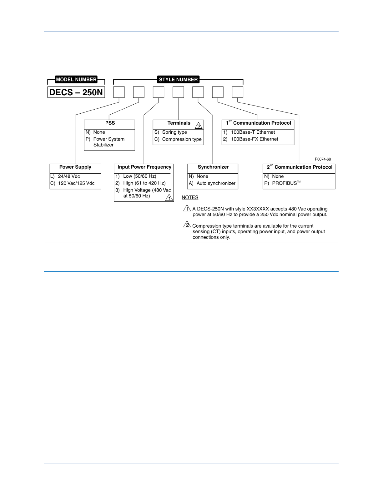
9440500990 Rev C 3
Style Number
The style number identification chart in Figure 1 defines the electrical characteristics and operational
features available in the DECS-250N.
Figure 1. DECS-250N Style Chart
Storage
If a DECS-250N will not be placed in service right away, store it in the original shipping carton in a
moisture- and dust-free environment. The temperature of the storage environment must be within the
range of –40 to 85°C (–40 to 185°F).
Electrolytic Capacitor Considerations
The DECS-250N contains long-life aluminum electrolytic capacitors. For a DECS-250N kept in storage as
a spare, the life of these capacitors can be maximized by energizing the device for 30 minutes once per
year. Refer to the energizing procedures provided in Maintenance.
DECS-250N Introduction

4 9440500990 Rev C
Introduction DECS-250N
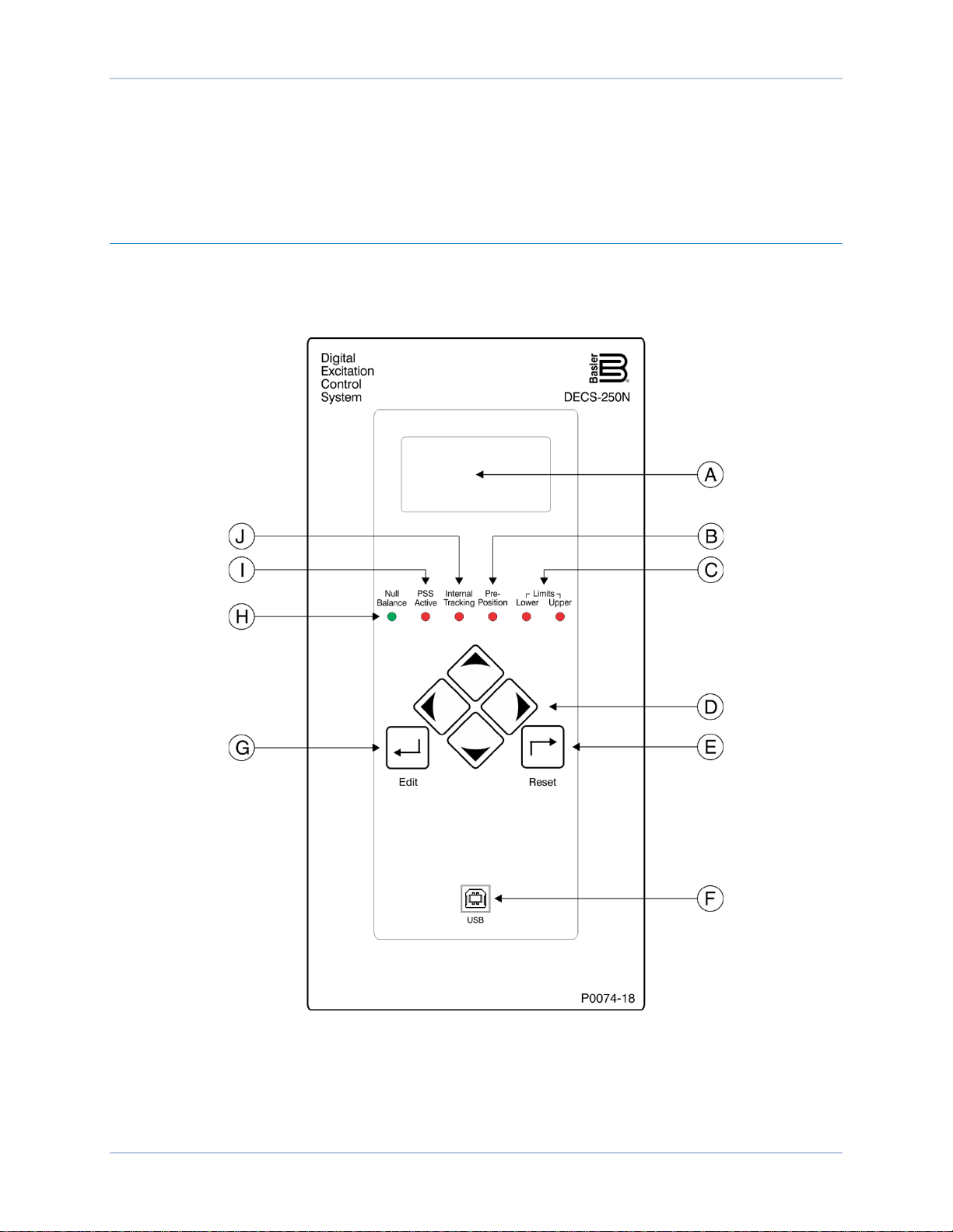
9440500990 Rev D 5
Controls and Indicators
All controls and indicators are located on the front panel and consist of pushbuttons, LED indicators, and
a liquid-crystal display (LCD).
Front Panel Illustration and Description
DECS-250N controls and indicators are illustrated in Figure 2 and described in Table 1. The locators and
descriptions of Table 1 correspond to the locators shown in Figure 2.
Figure 2. Front Panel Controls and Indicators
DECS-250N Controls and Indicators

6 9440500990 Rev D
Locator
Description
A
Display. The liquid crystal display (LCD) serves as a local source of information
64 dot pixel, backlit LCD displays white characters on a blue background.
B
Pre-Position Indicator. This red light emitting diode (LED) lights when the active mode
setpoint is at any of the three pre-position (predefined) settings.
C
Limit Indicators. Two red LEDs indicate when the active mode setpoint reaches the
minimum or maximum value.
D
Scrolling Pushbuttons. These four buttons are used to scroll up, down, left, and right
scrolling pushbuttons change the value of the variable.
E
Reset Pushbutton. This button cancels editing sessions, resets alarm annunciations
and latched alarm relays, and can be used for quick access to the metering screen.
F
Communication Port. This type B USB jack connects the DECS-250N with a PC
Caution
G
Edit Pushbutton. Pressing this button starts an editing session and enables changes to
pressed to save the settings changes.
H
Null Balance Indicator. This green LED lights when the setpoint of the inactive
mode.
I
PSS Active Indicator. This red LED lights when the integrated power system stabilizer
disturbance.
J
Internal Tracking Indicator. This red LED lights when any inactive mode (AVR, FCR,
“bumpless” transfer when changing active modes.
Table 1. Front Panel Control and Indicators Descriptions
provided by the DECS-250N. The LCD displays operating setpoints, loop gains,
metering, protection functions, system parameters, and general settings. The 128 by
through the menus displayed on the LCD (locator A). During an editing session, the left
and right scrolling pushbuttons select the variable to be changed and the up and down
operating BESTCOMSPlus® for local communication. BESTCOMSPlus is supplied
with the DECS-250N.
In accordance with the guidelines defined in USB standards, the USB
port on this device is not isolated. To prevent damage to a connected
PC or laptop, the DECS-250N must be properly tied to ground.
DECS-250N settings. At the conclusion of the editing session, the Edit pushbutton is
operating modes (AVR, FCR, FVR, var, and PF) match the setpoint of the active
is enabled and can generate a stabilizing signal in response to a power system
FVR, Var, or Power Factor) is tracking the setpoint of the active mode to achieve a
Menu Navigation
The DECS-250N provides local access to DECS-250N settings and metering values through a menu
structure displayed on the front panel LCD. An overview of the menu structure is illustrated in Figure 3.
Movement through the menu structure is achieved by pressing the four scrolling pu s hbuttons.
Controls and Indicators DECS-250N
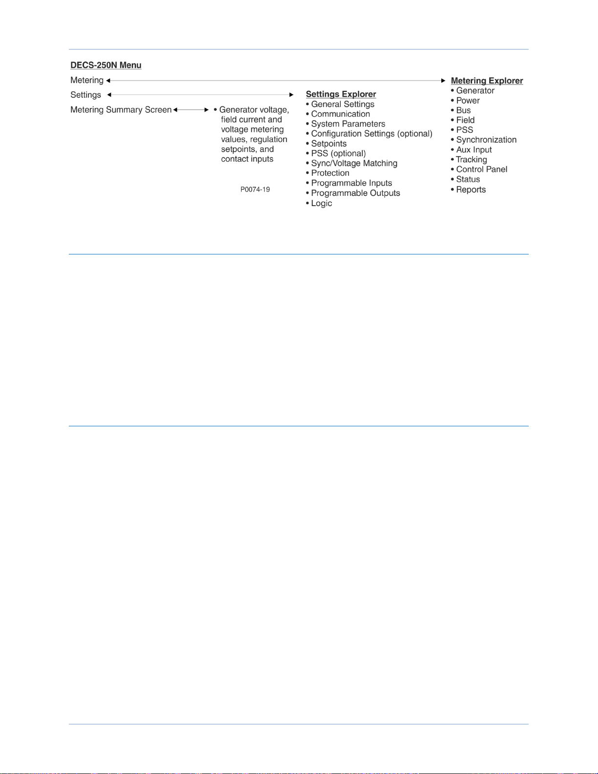
9440500990 Rev D 7
Figure 3. Menu Structure Overview
Adjusting Settings
A setting adjustment is made at the front panel by performing the following steps.
1. Navigate to the screen listing the setting to be changed.
2. Press the Edit button and enter the appropriate username and password to gain the needed level
of security access. (Information about implementing and using username and password
protection is provided in the Security chapter of this manual.)
3. Highlight the desired setting and press the Edit button to view the setting editing screen. This
screen lists the setting range or the permissible setting selection.
4. Use the scrolling pushbuttons to select the setting digits/selections and adjust/change the setting.
5. Press the Edit button to save the change.
Display Setup
BESTCOMSPlus Navigation Path: Settings Explorer, General Settings, Front Panel HMI
HMI Navigation Path: Settings, General Settings, Front Panel HMI
Front panel display appearance and behavior can be customized to meet user preferences and site
conditions. These BESTCOMSPlus settin gs are illustr a ted in Figure 4.
LCD
LCD setup includes a contrast adjustmentA to suit the viewing angle used or compensate for
environmental conditions. The ability to reverse the display colors
conditions and user preferences.
B
is provided to accommodate lighting
Sleep Mode
Sleep modeC reduces the demand on control power by turning off the LCD backlight when no pushbutton
activity is seen for the duration of the LCD Backlight Timeout setting
D
.
Language
Language modules are available for the DECS-250N. Once a language module is implemented it can be
enabled via the Language Selection sett ing
E
.
DECS-250N Controls and Indicators
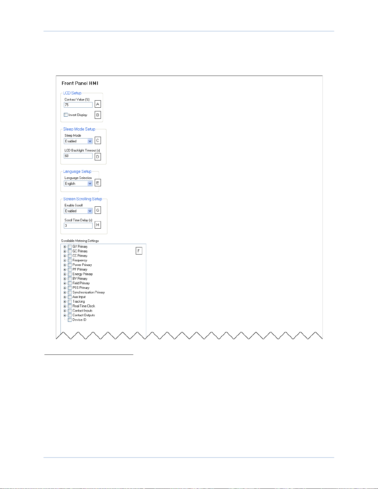
8 9440500990 Rev D
Screen Scrolling
The display can be set to automatically scroll through a user-selected listF of metered values. This feature
is enabled and disabled with the Enable Scroll setting
with the Scroll Time Delay setting
H
.
G
. The rate at which scrolling occurs is configured
Figure 4. Front Panel HMI Settings
A
Contrast Value (%): Adjustable from 0 to 100 in 1% increments.
B
Invert display: Deselect for white characters on a blue background. Select for blue characters on a white
background.
C
Sleep Mode: Enable or disable.
D
LCD Backlight Timeout: Adjustable from 0 to 120 seconds in 1 second increments.
E
Language Selection: Select English, Russian, Spanish, German, or Chinese.
F
Scrollable Metering Settings: Select from main categories of GV Primary, GC Primary, CC Primary,
Frequency, Power Primary, PF Primary, Energy Primary, BV Primary, Field Primary, PSS Primary,
Synchronization Primary, Aux Input, Tracking, Real Time Clock, Contact Inputs, Contact Outputs, or
Device ID. Follow this selection by the desired parameters within each category.
G
Enable Scroll: Enable or disable.
H
Scroll Time Delay (s): Adjustable from 1 to 600 seconds in 1 second increments.
Controls and Indicators DECS-250N

9440500990 Rev D 9
Desired Nominal
Excitation Power Voltage
Applied Operating
Power Voltage Range
63 Vdc
100 to 139 Vac
125 Vdc
190 to 277 Vac
250 Vdc
380 to 528 Vac, 50/60 Hz (style xx3xxxx)
DECS-250N
Style Number
Operating Power
Frequency Range
xx1xxxx
50/60 Hz
xx2xxxx
61 to 420 Hz
xx3xxxx
50/60 Hz (480 Vac input, 250 Vdc output)
Power Inputs
Power is applied to two separate inputs: control power and operating power. The control power input
supplies power to an internal power supply that provides power for logic, protection, and control functions.
The power stage uses the operating power input as the source for the converted excitation power that it
applies to the field.
Control Power
Two inputs supply the DECS-250N with control power. One input accepts dc control power and the other
input accepts ac control power. The level of acceptable control power voltage is determined by the style
number. One of two levels is possible. Style Lxxxxxx indicates a nominal voltage of 24 or 48 Vdc and
accepts a voltage range of 16 to 60 Vdc. Style Cxxxxxx indicates a nominal voltage of 120 Vac/125 Vdc
and accepts a voltage range of 90 to 150 Vdc and 82 to 132 Vac (50/60 Hz). One input (either dc or ac) is
sufficient for operation but two inputs provide redundancy (for style Cxxxxxx only). When both control
power inputs are used, an isolation trans former is required for the ac input. DC control power is applied at
terminals BATT+ and BATT–. AC control power is applied at terminals L and N.
Operating Power
Operating power is applied at terminals A, B, and C. To achieve the desired level of excitation, the
appropriate operating power input voltage must be applied. Table 2 lists the acceptable operating power
voltage ranges for the DECS-250N. The operating power frequency range for the DECS-250N is listed in
Table 3.
Table 2. DECS-250N Operating Power Specifications
Table 3. DECS-250N Operating Power Frequency Specifications
DECS-250N Power Inputs

10 9440500990 Rev D
Power Inputs DECS-250N

9440500990 Rev D 11
Power Stage
The DECS-250N supplies regulated dc excitation power to the field of a brushless exciter. Excitation
power is supplied at terminals F+ and F–.
DECS-250N power stage operating power accepts single- or thr ee-phase ac power from a transformer or
PMG. Power stage operating power is applied at terminals A, B, and C. The GND terminal serves as a
ground connection.
The DECS-250N power stage employs a six-SCR, full-wave bridge that converts the ac operating power
input into dc excitation power. It is capable of two-quadrant operation; it can produce negative as well as
positive output power as long as positive current is flowing in the machine field (in excess of the minimum
holding current required for the SCRs). The DECS-250N power stage is capable of supplying 20 Adc
continuously at nominal voltages of 63, 125, or 250 Vdc.
Nominal DECS-250N operating power levels include 480 Vac for a 250 Vdc continuous exciter field
requirement (style XX3XXXX), 240 Vac for a 125 Vdc requirement, or 120 Vac for a 63 Vdc requirement.
The frequency range of the operating power voltage is determined by the DECS-250N style number. Style
XX1XXXX indicates an operating power frequency of 50 to 60 hertz, style XX2XXXX indicates a
frequency of 61 to 420 hertz, and style XX3XXXX limits the frequency to 50 or 60 hertz (for an operating
voltage of 480 Vac).
Field Transient Protec t ion
Fault conditions such as generator overloading or loss of synchronism can induce transients into the field
circuit. If this energy is not dissipated, it has the poten t ial to dam age the pow er stage SCRs. The
DECS-250N has two modes of field transient protection.
Most voltage transients are less than 150 microseconds in duration and are limited to a safe level by
internal DECS-250N components.
During major system faults, an SCR crowbar circuit protects the DECS-250N power stage. When field
overvoltage is detected, the power stage SCR firing pulses are blocked, the crowbar circuit is energized,
and a crowbar annunciation is made. During a normal shutdown, the same actions are taken but no
crowbar annunciation is made.
Inverting Style Excitation System Compatibility
The DECS-250N power stage can be configured for operation in the negative direction to supply the
control windings of an inverting style excitation system.
DECS-250N Power Stage

12 9440500990 Rev D
Power Stage DECS-250N
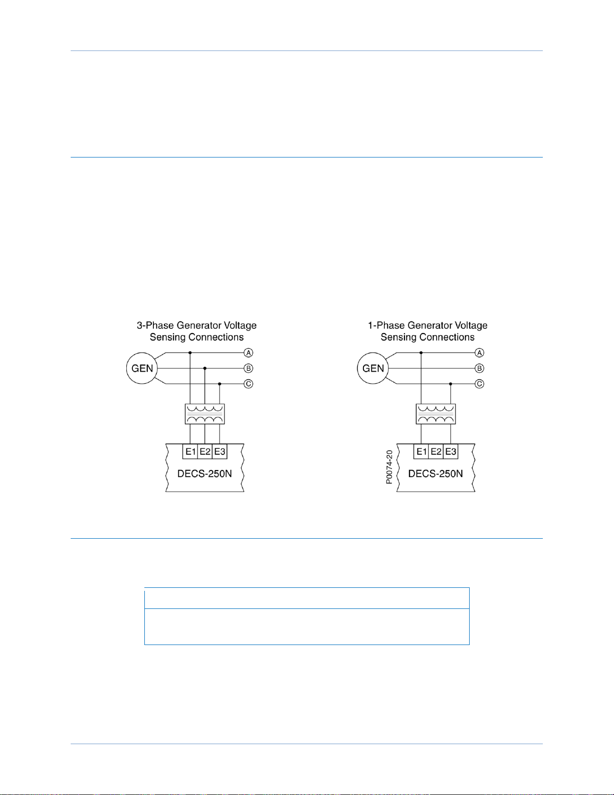
9440500990 Rev D 13
Note
Voltage and Current Sensing
The DECS-250N senses generator voltage, generator current, and bus voltage through dedicated,
isolated inputs.
Generator Voltage
Three-phase generator sensing voltage is applied to DECS-250N terminals E1, E2, and E3. This sensing
voltage is typically applied through a user-supplied voltage transformer, but may be applied directly.
These terminals accept three-phase, three-wire connections at terminals E1 (A), E2 (B), and E3 (C) or
single-phase connections at E1 (A) and E3 (C).
The generator voltage sensing input accepts a maximum voltage of 600 Vac and has a burden of less
than 1 VA.
The transformer primary and secondary winding voltages are entered in settings that the DECS-250N
uses to interpret the applied sensing voltage and calculate system parameters. The phase rotation of the
generator sensing voltage can be configured as ABC or ACB. Information about configuring the
DECS-250N for the generator sensing voltage is provided in the Configuration chapter of this manual.
Typical generator voltage sensing connections are illustrated in Figure 5.
Figure 5. Typical Generator Voltage Sensing Connections
Generator Current
Generator current sensing inputs consist of three phase-sensing inputs and a sensing input for crosscurrent compensation.
Current transformer (CT) grounding should be applied in accordance
with local codes and conventions.
Phase Sensing
Three-phase generator sensing current is applied to DECS-250N terminals CTA+ and CTA–, CTB+ and
CTB–, and CTC+ and CTC– through user-supplied current transformers (CTs). Single-phas e gen erat or
sensing current is applied to DECS-250N terminals CTB+ and CTB–. The DECS-250N is compatible with
CTs having 5 Aac or 1 Aac nominal secondary ratings. The DECS-250N uses this secondary rating, along
with the CT nominal primary ratings to interpret the sensed current and calculate system parameters.
DECS-250N Voltage and Current Sensing
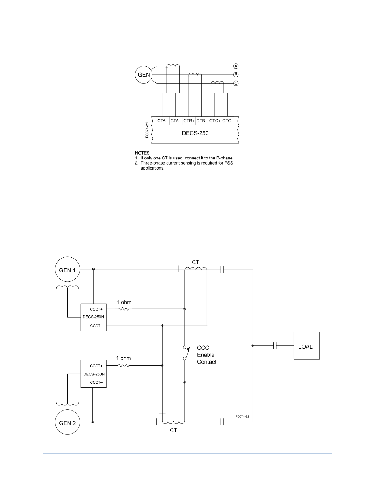
14 9440500990 Rev D
Information about configuring the DECS-250N the generator sensing voltage is provided in the
Configuration chapter of this manual. Typical generator phase-current sensing connections are shown in
Figure 6.
Figure 6. Typical Generator Current Sensing Connections
Cross-Current Compensation
Cross-current compensation (reactive differential) mode allows two or more paralleled generators to
share a common load. As shown in Figure 7, each generator is controlled by a DECS-250N using the
DECS-250N cross-current compensation input (terminals CCCT+ and CCCT–) and a dedicated, external
current transformer (CT) to sense generator current. The resistors shown in Figure 7 are used to set the
burden and may be adjusted to suit the application. Ensure that the power rating of the resistors is
adequate for the application.
Figure 7. Connections for Cross-Current Compensation
Voltage and Current Sensing DECS-250N
Loading...