


 Loading...
INSTRUCTION MANUAL
FOR
CBS 212A
Current Boost System
Publication: |
9270700990 |
|
Revision: |
F |
Apr-15 |

9270700990 |
i |
Preface
This instruction manual provides information about the installation and operation of the CBS 212A Current Boost System. To accomplish this, the following information is provided:
•General information and functional description
•Controls and indicators
•Installation, calibration, and testing
•Specifications
Conventions Used in this Manual
Important safety and procedural information is emphasized and presented in this manual through warning, caution, and note boxes. Each type is illustrated and defined as follows.
Warning!
Warning boxes call attention to conditions or actions that may cause personal injury or death.
Caution
Caution boxes call attention to operating conditions that may lead to equipment or property damage.
Note
Note boxes emphasize important information pertaining to installation or operation.
CBS 212A |
Preface |
ii |
9270700990 |
12570 State Route 143
Highland IL 62249-1074 USA
www.basler.com
info@basler.com
Tel: +1 618.654.2341
Fax: +1 618.654.2351
© 2015 by Basler Electric All rights reserved
First printing: November 2001
Warning!
READ THIS MANUAL. Read this manual before installing, operating, or maintaining the CBS 212A. Note all warnings, cautions, and notes in this manual as well as on the product. Keep this manual with the product for reference. Only qualified personnel should install, operate, or service this system. Failure to follow warning and cautionary labels may result in personal injury or property damage. Exercise caution at all times.
Basler Electric does not assume any responsibility to compliance or noncompliance with national code, local code, or any other applicable code. This manual serves as reference material that must be well understood prior to installation, operation, or maintenance.
For terms of service relating to this product and software, see the Commercial Terms of Products and Services document available at www.basler.com/terms.
This publication contains confidential information of Basler Electric Company, an Illinois corporation. It is loaned for confidential use, subject to return on request, and with the mutual understanding that it will not be used in any manner detrimental to the interests of Basler Electric Company and used strictly for the purpose intended.
It is not the intention of this manual to cover all details and variations in equipment, nor does this manual provide data for every possible contingency regarding installation or operation. The availability and design of all features and options are subject to modification without notice. Over time, improvements and revisions may be made to this publication. Before performing any of the following procedures, contact Basler Electric for the latest revision of this manual.
The English-language version of this manual serves as the only approved manual version.
Preface |
CBS 212A |
9270700990 |
iii |
Contents |
|
Introduction ................................................................................................................................................. |
1 |
Functional Description ............................................................................................................................... |
3 |
Introduction................................................................................................................................................ |
3 |
Current Boost Module................................................................................................................................ |
3 |
Controls and Indicators.............................................................................................................................. |
5 |
Installation ................................................................................................................................................... |
7 |
Mounting.................................................................................................................................................... |
7 |
Current Boost Module............................................................................................................................ |
7 |
Current Transformers (CTs) .................................................................................................................. |
8 |
Interconnection ........................................................................................................................................ |
11 |
CT Connections ................................................................................................................................... |
11 |
Current Boost Module Connections..................................................................................................... |
11 |
Calibration ............................................................................................................................................... |
13 |
Sensing Voltage Selection................................................................................................................... |
13 |
Output Limit Selection.......................................................................................................................... |
13 |
Output Limit Adjustment ...................................................................................................................... |
13 |
Operating Point Adjustment................................................................................................................. |
14 |
Testing........................................................................................................................................................ |
15 |
Installation Verification............................................................................................................................. |
15 |
Calibration Verification............................................................................................................................. |
15 |
Unloaded Generator ............................................................................................................................ |
15 |
Loaded Generator................................................................................................................................ |
16 |
Power Verification.................................................................................................................................... |
16 |
Specifications............................................................................................................................................ |
17 |
Operational Specifications....................................................................................................................... |
17 |
Output Power ....................................................................................................................................... |
17 |
Sensing Voltage................................................................................................................................... |
17 |
Output Limiting..................................................................................................................................... |
17 |
Operation Point Adjustment Range ..................................................................................................... |
17 |
Dropout Ratio....................................................................................................................................... |
17 |
Power Dissipation ................................................................................................................................ |
17 |
General Specifications............................................................................................................................. |
17 |
Type Tests ........................................................................................................................................... |
17 |
Temperature ........................................................................................................................................ |
17 |
EAC Mark (Eurasian Conformity) ........................................................................................................ |
17 |
Weight.................................................................................................................................................. |
17 |
Revision History........................................................................................................................................ |
19 |
CBS 212A |
Contents |

iv |
9270700990 |
Contents |
CBS 212A |
9270700990 Rev F |
1 |
Introduction
The CBS 212A Current Boost System assists Basler SSR-series voltage regulators during generator overload conditions and supplies the exciter field during generator short-circuits. When used with 3-wire or 4-wire generators, the CBS 212A supports sustained single-phase and multiple-phase, line-to-line faults. In addition, the CBS 212A permits 4-wire generators to support A-phase and B-phase line-to- neutral faults.
The CBS 212A assembly consists of a Current Boost Module and two current transformers (CTs). The Current Boost Module is designed for behind-the-panel mounting.
An Operating Point Adjustment control and Operating Point Indication LED are located on the front panel of the Current Boost Module. An Output Limit Adjustment control is located on the bottom panel of the Current Boost Module.
Special power CTs connect to two phases of the generator output and provide current to the Current Boost Module. The Installation chapter provides details about CT selection.
CBS 212A |
Introduction |

2 |
9270700990 Rev F |
Introduction |
CBS 212A |
9270700990 Rev F |
3 |
Functional Description
Introduction
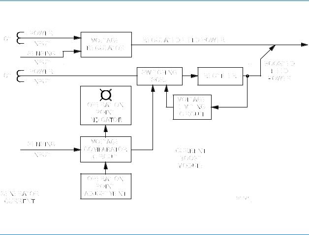
CBS 212Afunctions are illustrated in Figure 1 and described in the following paragraphs.
Figure 1. Function Block Diagram
Current Boost Module
The Current Boost Module rectifies the ac current received from the CTs and provides dc current boost to the generator exciter field.
During normal generator operation, power from the generator output provides sufficient exciter field power and the CBS 212A remains dormant. During normal operation, the CTs are effectively shorted by the internal SCRs of the CBS 212A. Normal generator operation is indicated by the Operating Point Indication LED being lit.
If the generator output voltage decreases below the operating-point setting, the CBS 212A detects the voltage drop, turns off the Operating Point Indication LED, and removes the SCR “short-circuit” from the CTs. The CBS 212A then provides full current boost to the generator exciter until the voltage returns to a level just above the operating point setting. The Controls and Indicators and Installation chapters provide information about setting the Operating Point Adjustment.
An adjustable voltage limiting circuit prevents the Current Boost Module output from exceeding the specified percentage of the nominal output voltage (60, 120, or 220 Vdc). The Output Limit Select Jumpers are used to select the nominal output voltage (60, 120, or 220 Vdc) and the Output Limit Adjustment is used to set the desired percentage of the nominal output voltage. The Output Limit Adjustment is adjustable over a range of 50 to 100 percent of the jumper-selected nominal output voltage.
CBS 212A |
Functional Description |
Loading...