


BE1-25
Table of contents
 Loading...
INSTRUCTION MANUAL
FOR
SYNC-CHECK RELAY
BE1-25
Publication: 9170200990
Revision: U 07/13


INTRODUCTION
This instruction manual provides information about the operation and installation of the BE1-25 Sync-
Check relay. To accomplish this, the following information is provided:
• General Information and Specifications
• Controls and Indicators
• Functional Description
• Installation
• Testing
WARNING!
To avoid personal injury or equipment damage, only qualified personnel should
perform the procedures in this manual.
NOTE
Be sure that the BE1-25 is hard-wired to earth ground with no smaller than 12
AWG copper wire attached to the ground terminal on the rear of the unit case.
When the BE1-25 is configured in a system with other devices, it is
recommended to use a separate lead to the ground bus from each unit.
9170200990 Rev U BE1-25 Introduction i

First Printing: 1985
Printed in USA
© 2013 Basler Electric, Highland Illinois 62249 USA
All Rights Reserved
July 2013
It is not the intention of this manual to cover all details and variations in equipment, nor does this manual
provide data for every possible contingency regarding installation or operation. The availability and design
of all features and options are subject to modification without notice. Should further information be
required, contact Basler Electric.
BASLER ELECTRIC
12570 STATE ROUTE 143
HIGHLAND IL 62249-1074 USA
http://www.basler.com, info@basler.com
PHONE +1 618.654.2341 FAX +1 618.654.2351
CONFIDENTIAL INFORMATION
of Basler Electric, Highland Illinois, USA. It is loaned for confidential use, subject
to return on request, and with the mutual understanding that it will not be used in
any manner detrimental to the interest of Basler Electric.
ii BE1-25 Introduction 9170200990 Rev U

REVISION HISTORY
The following information provides a historical summary of the changes made to the BE1-25 instruction
manual (9170200990). Revisions are listed in reverse chronological order.
Manual
Revision and Date
Change
U, 07/13
• Added Caution for contact sensing in Specifications.
• Minor text and formatting edits.
T, 10/12
• Standardized case and cover drawings in Section 4.
S, 03/11
• Updated power supply burden data in Section 1.
• Updated GOST-R statement in Section 1.
• Updated Storage Statement in Section 4.
R, 09/07
• Moved content of Section 6, Maintenance to Section 4.
• Added manual part number and revision to all footers.
• Updated power supply burden data in Section 1.
• Updated Target Indicator description in Section 3.
P, 11/06
• Updated Output Specs in Section 1.
• Added footnote to Figures 1-2 and 1-3.
• Updated drawings of case cover in Section 4, Installation.
• Updated front panel drawing in Section 2, Controls and Indicators.
• Moved manual Revision History to the front of manual.
• Updated drawing on front cover.
N, 08/02
• Updated drawings in the manual to label terminal 15 (COM) as Vctrl.
• Corrected various minor errors throughout the manual.
M, 02/01
• Changed the Specifications, illustrations, and the descriptions
throughout the manual for the minimum voltage required to operate
the sync-check function.
• Corrected Figure 1-6, Style Chart.
• Added contact-sensing burden and enhanced Surge Withstand
Capability description.
• Added new covers information.
• Changed Section 5, Testing, to reflect the minimum voltage
requirements for sync-check function.
L, 08/98
• Added Power Supply information to Section 3 and added new wide
range power supply information to Section 1.
• Corrected Style Chart by changing Power Supply Type T from 230
Vac to 240 Vac.
• Moved Testing information from Section 4 to new Section 5, Testing.
• Added new outline dimensions to include all options (S1 Case,
Double-Ended, Semi-Flush, and Projection Mounting).
• Corrected ground symbol in Figure 4-7, Internal Diagram.
• Updated front cover and Manual Change information.
K, 12/97
• Deleted the reference to Service Manual 9170200620 on page 1-1.
• Corrected an error found on page 1-11 in Minimum Voltage
Requirement from “45 ±2 Vac” to “80 Vac”.
• Updated front cover and Manual Change information.
9170200990 Rev U BE1-25 Introduction iii

Manual
Revision and Date
Change
J, 10/97
• Added three new types (A, B, & C) to Option 2. This included new
paragraphs describing Average Detectors.
H, 01/96
• Corrected power supply type P, voltage input, and range from Vdc to
Vac.
• Minor page layout changes developed from using a word processor
application upgrade.
G, 01/95
• Reformatted instruction manual as Windows Help file for electronic
documentation.
F, 03/92
• Added new Figure 4-7, Internal Diagram and incorporated new
instruction manual format.
E, 05/90
• Edited General Information section and Controls and Indicators
section for clarification.
• Revised Figure 4-12 and edited Operational Test Procedure.
D, 07/88
• Added test plug/adapter information.
• Added TB2 terminal strip to connection diagrams.
C, 06/87
• Revised manual to reflect introduction of power supply status option.
B, 12/86
• Added note to Style Chart.
• Added footnote to power supply table and deleted the words make
and from inductive contact specification.
• Corrected and clarified phase angle specifications.
• Corrected typographical errors on Slip Frequency graph.
A, 11/85
• Added information to Figures 4-4, 4-9, and 4-10.
• Added storage recommendation paragraph.
iv BE1-25 Introduction 9170200990 Rev U

CONTENTS
SECTION 1 • GENERAL INFORMATION ................................................................................................ 1-1
SECTION 2 • CONTROLS AND INDICATORS ........................................................................................ 2-1
SECTION 3 • FUNCTIONAL DESCRIPTION ........................................................................................... 3-1
SECTION 4 • INSTALLATION .................................................................................................................. 4-1
SECTION 5 • TESTING ............................................................................................................................ 5-1
9170200990 Rev U BE1-25 Introduction v

This page intentionally left blank.
vi BE1-25 Introduction 9170200990 Rev U

SECTION 1 • GENERAL INFORMATION
TABLE OF CONTENTS
SECTION 1 • GENERAL INFORMATION ................................................................................................ 1-1
INTRODUCTION ................................................................................................................................... 1-1
DESCRIPTION ...................................................................................................................................... 1-1
APPLICATION ....................................................................................................................................... 1-1
SYNC-CHECK FUNCTION .................................................................................................................... 1-2
CONTACT SENSING ............................................................................................................................ 1-2
VOLTAGE MONITOR OPTIONS ........................................................................................................... 1-2
Mode Switches ................................................................................................................................... 1-2
Condition Switches ............................................................................................................................. 1-3
Voltage Difference .............................................................................................................................. 1-3
Option 2-R, 2-T, or 2-U (Phasor Voltage Difference) ......................................................................... 1-4
Option 2-A, 2-B, or 2-C (Average Voltage Difference) ....................................................................... 1-5
Output Relay ...................................................................................................................................... 1-6
OTHER OPTIONS ................................................................................................................................. 1-6
Expandable Window ........................................................................................................................... 1-6
External Condition Switches .............................................................................................................. 1-6
Push-to-Energize Output Pushbuttons ............................................................................................... 1-7
MODEL AND STYLE NUMBER............................................................................................................. 1-7
Style Number Example ....................................................................................................................... 1-7
SPECIFICATIONS ................................................................................................................................. 1-9
Figures
Figure 1-1. Voltage Monitor Acceptance Zones ........................................................................................ 1-3
Figure 1-2. Closing Zone (Phasor Sensing) .............................................................................................. 1-4
Figure 1-3. Closing Zone (Average Sensing) ............................................................................................ 1-4
Figure 1-4. Closing Zone Calculation Diagram (Phasor Sensing) ............................................................ 1-5
Figure 1-5. Closing Zone Diagram (Average Sensing) ............................................................................. 1-6
Figure 1-6. Style Number Identification Chart ........................................................................................... 1-8
Tables
Table 1-1. Power Supply ........................................................................................................................... 1-9
9170200990 Rev U BE1-25 General Information i

This page intentionally left blank.
ii BE1-25 General Information 9170200990 Rev U

SECTION 1 • GENERAL INFORMATION
INTRODUCTION
These instructions provide information concerning the operation and installation of BE1-25 Sync-Check
Relays. To accomplish this, the following is provided:
• Specifications
• Functional characteristics
• Mounting information
• Setting procedures and examples
Relays with a Type T power supply require a Contact Sensing Module, which comes supplied with its own
instructions, publication 9170206990.
These instructions may be used in place of all earlier editions. For change information, see Revision
History in the manual Introduction.
It is not the intention of these instructions to cover all details and variations in equipment, nor does this
manual provide data for every possible contingency regarding installation or operation. The availability
and design of all features and options are subject to modification without notice. Should further
information be required, contact Customer Service, Basler Electric Company, Highland, IL.
DESCRIPTION
The BE1-25 is a solid-state synchronism check relay designed to permit breaker closure when the desired
maximum phase angle conditions have held for a specified minimum time. The maximum allowable phase
angle and time delay requirements can be set on front panel thumbwheel switches. Five voltage
measuring options are available that identify significant line and bus voltage conditions, and this
information is used to influence the relay output.
APPLICATION
BE1-25 Sync-Check Relays are recommended for situations that require verification of synchronism prior
to closing a circuit breaker. Typical applications are:
• Paralleling a generator to a system.
• Reestablishing a connection between two parts of a power system.
• Supervising fast transfer schemes, where fast pickup and dropout of the phase measuring circuit
are required.
If optional voltage measuring circuits are incorporated, the BE1-25 can determine whether an input is live,
dead, or in an overvoltage state.
WARNING!
To avoid personal injury or equipment damage, only qualified personnel should
perform the procedures presented in these instructions.
NOTE
Voltage sensing circuits are guaranteed to operate at a minimum voltage of 60
volts. They are guaranteed not to operate at voltages less than 20 volts. Some
units may operate at voltages in between these two levels because of the
individual characteristics of specific components. Minimum voltage detection is
usually in the range of 45 to 55 volts
9170200990 Rev U BE1-25 General Information 1-1

SYNC-CHECK FUNCTION
BE1-25 Sync-Check function measures the phase angle between single-phase voltages of line and bus.
Then sync-check verifies that this angle is less than the front panel PHASE ANGLE selector setting. If the
measured angle has met these criteria for the time period defined by the front panel TIME DELAY setting,
the SYNC output contact closes.
The allowable phase angle is adjustable over the range of 1 to 99 degrees. The time delay is adjustable
over either of two ranges: 1 to 99 cycles, 50/60 hertz (using the bus frequency as the reference), or 0.1
to 99 seconds (using the internal crystal controlled oscillator as the reference).
An optional target may be specified to indicate operation of the Sync-Check function.
CONTACT SENSING
To control operation of the relay, an input from the breaker auxiliary 52b contact is required to signal the
breaker status. If the breaker is open, the relay is enabled to perform its function. When the breaker
closes, the 52b input changes state and causes the relay to terminate its close signal.
Two configurations of the 52b contact sensing input are available to provide additional flexibility for the
protection circuit designer:
• Isolated contact sensing monitors a current supplied by the relay through an isolated contact.
• Non-isolated contact sensing monitors the presence of voltage at its input due to the closure of a
contact.
See Figure 4-11 for typical control circuit connections for each configuration. Also, see Figure 4-12 if a
Type T power supply has been selected.
VOLTAGE MONITOR OPTIONS
Mode Switches
Two Mode switches are located on the Voltage Monitor card. Mode Switch No. 1 serves the bus Voltage
Monitor function. Mode Switch No. 2 serves the line Voltage Monitor function. Mode switch positions are
as follows:
NORMAL Mode (Up) - allows measuring elements to establish live and dead reference levels for
the input level.
NOT-OV Mode (Down) - allows measuring elements to establish live and Not-Overvoltage
reference levels for the input level.
When a Mode Switch is in the NORMAL Mode position (Up), a dead level is defined as a monitored
voltage level below the DEAD reference setting. See Figure 1-1 for voltage monitor acceptance zones. A
live level is defined as a monitored voltage above the LIVE reference setting.
When a Mode Switch is in the NOT-OV Mode position (Down), a dead level is defined as a monitored
voltage less than the LIVE reference setting, and a live level is defined as a monitored voltage greater
than the LIVE reference setting, but less than the NOT-OV setting. (An input is considered over-voltage
when it exceeds the NOT-OV reference setting.)
It is permissible to operate the line input in either the same mode or a different mode than the bus input.
This flexibility allows the BE1-25 to be used, for example, to close a generator breaker onto a dead bus,
or to prevent closure if the generator and/or bus voltage is too high.
See Table 2-1, callout R, for a complete description and precautions on setting the Mode Switches. The
location of the switches is shown in Figure 2-2. Also, see Condition and Mode Switches in Section 5.
1-2 BE1-25 General Information 9170200990 Rev U
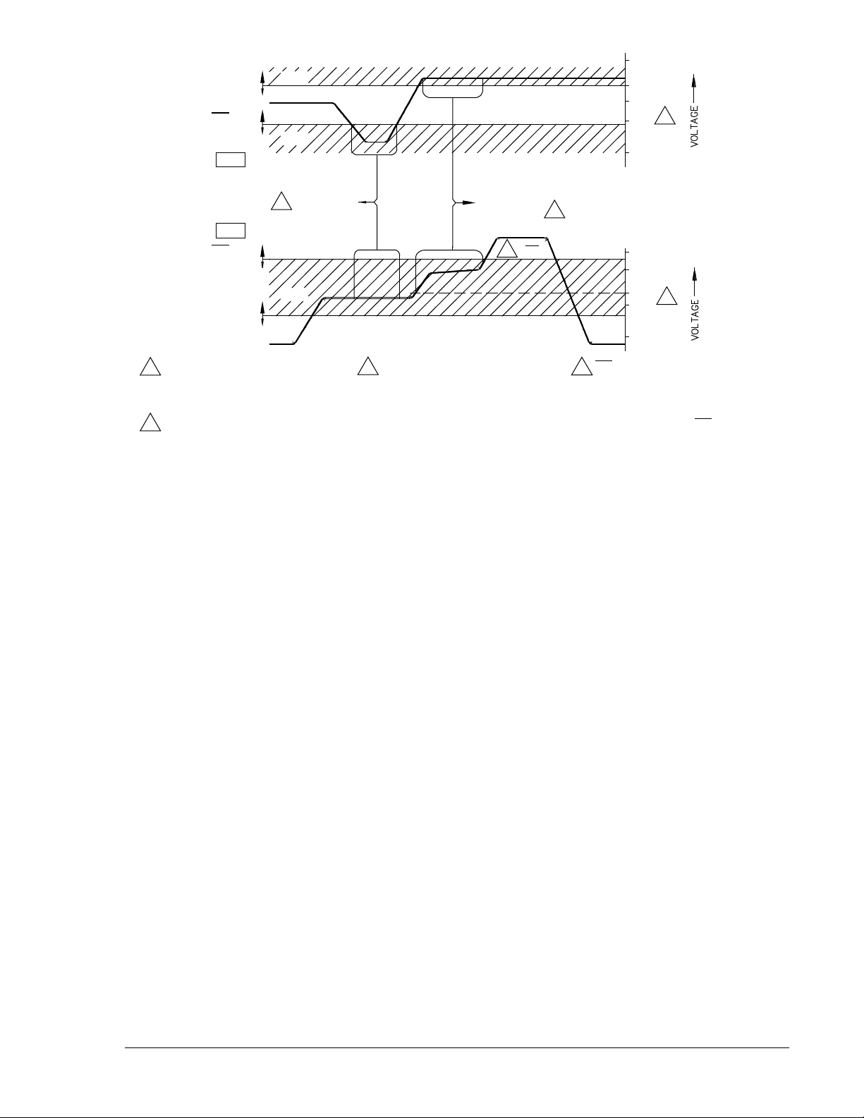
Figure 1-1. Voltage Monitor Acceptance Zones
Condition Switches
Five Condition Switches are located on the Voltage Monitor Card, each with two positions to select ON
(Down) and OFF (Up). When ON, Condition Switch No. 1 programs the relay to require recognition that
the line and bus are not in an overvoltage condition (NOT OV) before the SYNC output is allowed.
Condition Switches No. 2 through No. 5 modify the voltage monitor response according to a programmed
set of external conditions. The possible external conditions for each of these four switches are:
Switch 2. Live Line/Live Bus (LL-LB)
Switch 3. Dead Line/Live Bus (DL-LB)
Switch 4. Live Line/Dead Bus (LL-DB)
Switch 5. Dead Line/Dead Bus (DL-DB)
When a selected condition has been recognized, the voltage monitor circuit may be instructed to
immediately energize the Sync-Check output relay, or (if provided) the Voltage Monitor output relay. (See
Figure 1-1, Note 1.)
See Table 2-1, callout S, for a complete description and precautions on setting the Conditions Switches.
The location of the switches is shown in Figure 2-2.
Voltage Difference
A voltage monitor is available that checks the phasor or average voltage difference between the two
inputs. This can be used to prevent the closure of a generator breaker if the voltage difference is too great
(even if the phase angle and voltage level monitoring circuits indicate that proper closing conditions are
otherwise present).
The voltage difference option (included with option 2-A, 2-B, 2-C, 2-R, 2-T or 2-U) is typically used to
reduce the amount of possible system shock or transients when closing a breaker. This option compares
the voltage between line and bus against a selected limit, and initiates either an enable or an inhibit signal
for the sync-check logic, thereby narrowing the voltage across the breaker contacts (as compared to a
simple sync-check acting alone). Figure 1-2 shows closing zones obtained by combining phasor voltage
difference, phase angle limit, and line and bus live/dead voltage limits. Figure 1-3 shows closing zones
obtained by combining average voltage difference, phase angle limit, and line and bus live/dead voltage
limits.
LL ADJ
=100V
DL / OV ADJ
=40V
LINE
DEAD
LINE VOLTAGE
LIVE
135V (MAX)
100V
50V
10V (MIN)
2
LIVE LINE/
LIVE BUS
CONDITION
4
OV
135V (MAX)
100V
50V
10V (MIN)
P0004-36
BUS
1
DEAD LINE/
LIVE BUS
CONDITION
LIVE
DB / OV ADJ
=120V
LB ADJ
=35V
BUS VOLTAGE
60V FIXED MINIMUM VOLTAGE
LIMIT (LIVE LINE/LIVE BUS
CONDITION SYNC-CHECK
3
NOTES:
SYNC RELAY CONTACTS
CLOSED BY VOLTAGE MONITOR
SYNC-CHECK LOGIC ENABLED
2
1
LOGIC
4 OV EXCEEDED, SYNC-CHECK
TO ON PERMITS
LOGIC NOT ENABLED (SETTING
MODE SWITCH NO. 1 TO ON
AND CONDITION SWITCH NO. 1
FUNCTION ONLY)
OV)
3
3
9170200990 Rev U BE1-25 General Information 1-3
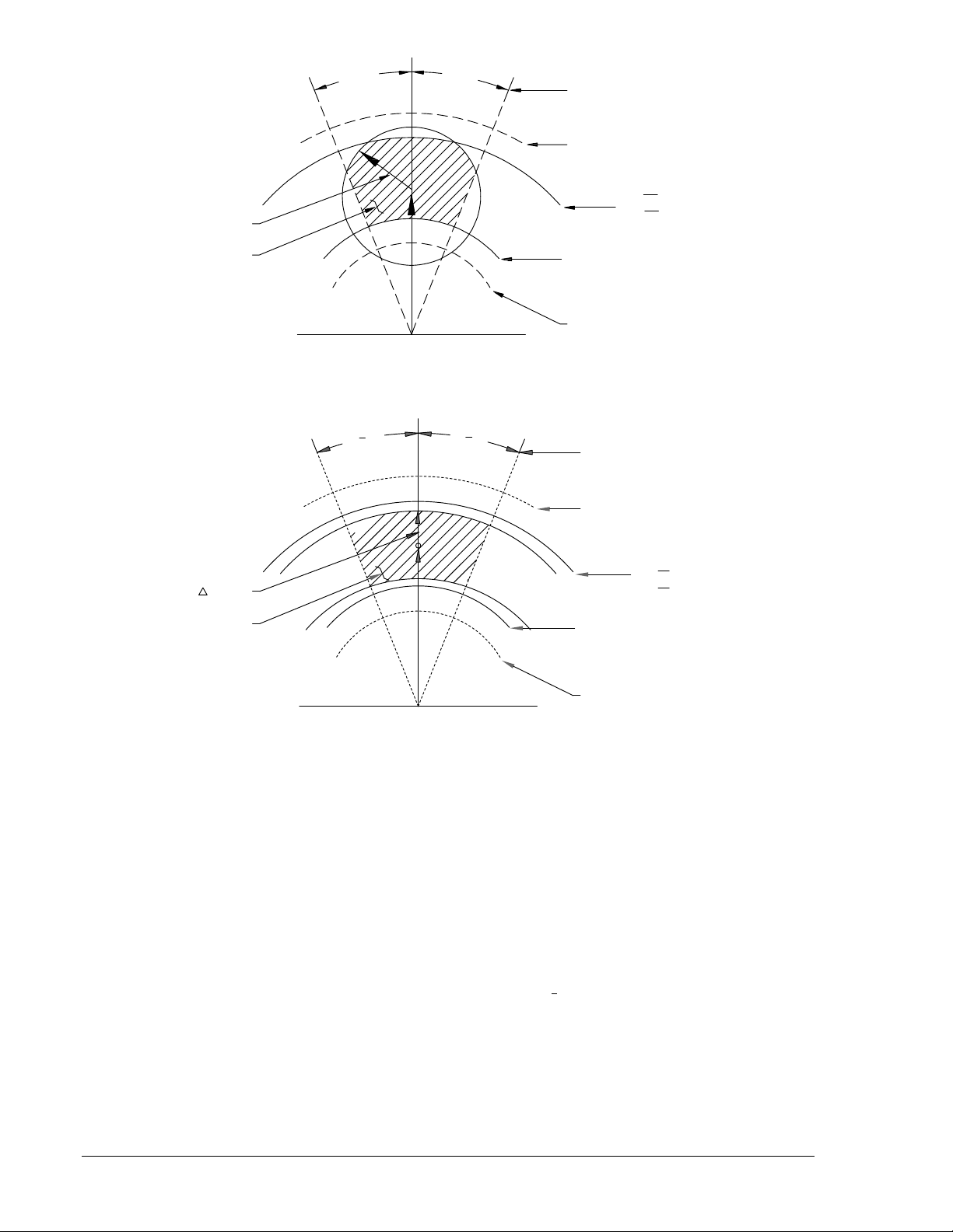
Figure 1-2. Closing Zone (Phasor Sensing)
Figure 1-3. Closing Zone (Average Sensing)
∗ Lines apply only if using the NOT-OV mode setting. When operating in NORMAL mode, the 135V
(MAX) line applies as an upper limit.
Option 2-R, 2-T, or 2-U (Phasor Voltage Difference)
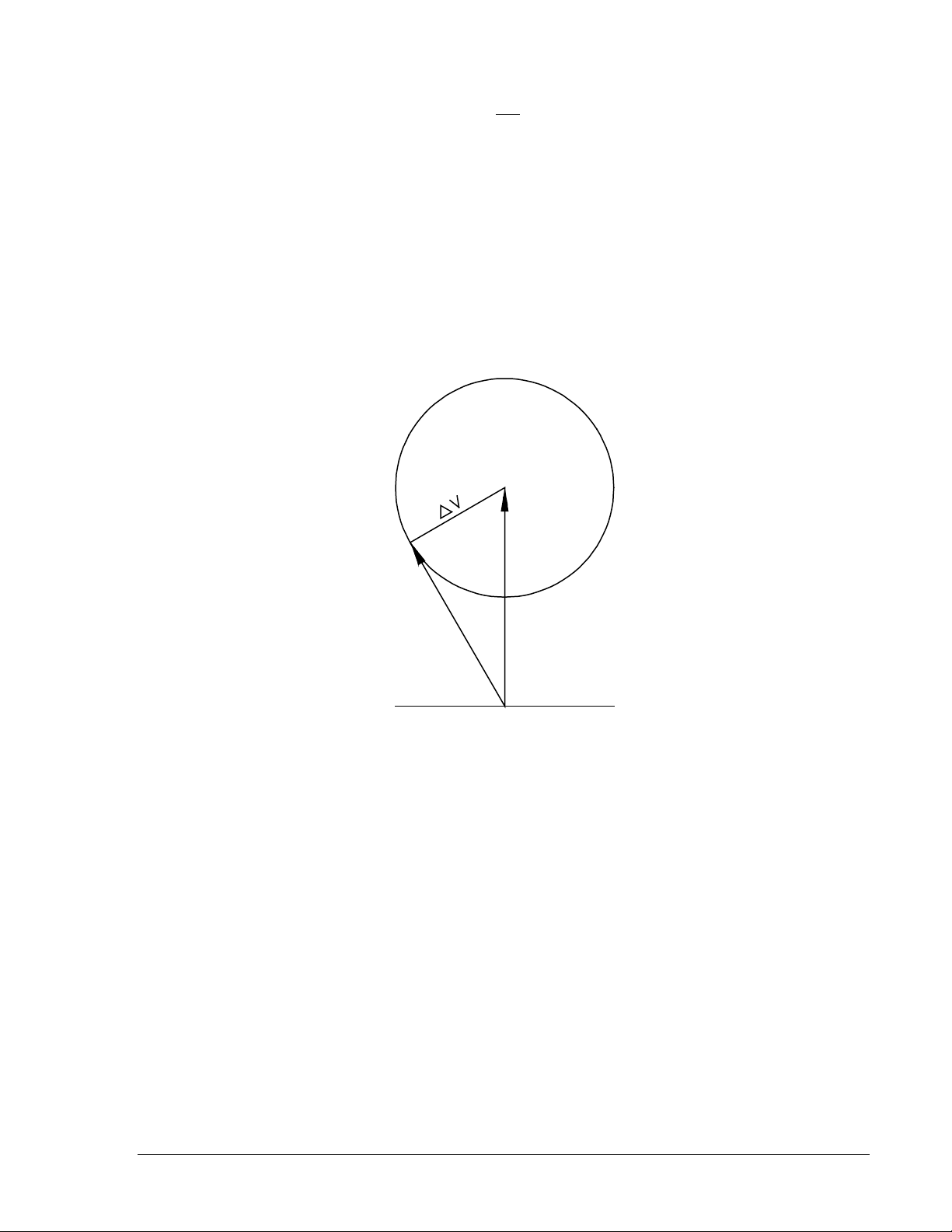
Figure 1-4 may be used as an aid in formulating the voltage difference control settings. Note that the
center reference phasor (
V
B
) represents the monitored bus voltage, while the adjacent phasor (
V
L
)
represents the monitored line voltage. The voltage difference control (∆V) forms an area of acceptance
limit when rotated through 360 degrees. This allows either the voltage difference or the phase angle to be
selected, and the remaining value to be calculated.
Calculate the voltage difference (∆V) using the law of cosines. The equation is:
∆V V V V V
L B L B
=
+ − ⋅ ⋅ ⋅( cos )
2 2
2
1
2
θ
(1)
When
V
L
is tangent to the voltage difference circle, the ∆V phasor is perpendicular to
V
L
at the phase
angle limit. Accordingly, the voltage difference or the phase angle can be calculated by equations 2 and
3, respectively.
θ
V ADJ∆
ALLOWABLE
CLOSING ZONE
PHASE ANGLE ADJ
135V (MAX)
DL /OV ADJ (LINE) ٭
DB /OV ADJ (BUS) ٭
LL ADJ (LINE)
LB ADJ (BUS)
60V (APPROX.) FIXED
MINIMUM VOLTAGE
P004-35
θ
PHASE ANGLE ADJ
135
V (
MAX
)
DL/
OV ADJ
(LINE)
٭
DB
/
OV ADJ (
BUS
)
٭
LL ADJ (LINE)
LB ADJ (BUS)
60V (APPROX.) FIXED
MINIMUM VOLTAGE
0
0
V ADJ
ALLOWABLE
CLOSING ZONE
P004-38
1-4 BE1-25 General Information 9170200990 Rev U
∆V V sin
B
= θ
(2)
θ
∆
=
−
sin
V
V
1
B
(3)
where:
∆V = Voltage Difference
V
L
= Line Voltage
V
B
= Bus Voltage
θ = Phase Angle
Note that the point where
V
L
is tangent to the voltage difference circle represents the most extreme
condition of
θ for a closure. Assuming that a constant voltage difference exists, the following condition is
valid: If the magnitude of the line voltage decreases, the phase angle must also decrease to allow sync-
acceptance. Therefore, the minimum line voltage possible for sync-acceptance occurs at zero phase
angle.
Figure 1-4. Closing Zone Calculation Diagram (Phasor Sensing)
Option 2-A, 2-B, or 2-C (Average Voltage Difference)
This option is similar to option 2-T, 2-R, or 2-U except for the sensing method. This option provides
average voltage sensing instead of phasor voltage sensing. This provides a constant ∆V setting
independent of the phase relationship between the line and bus voltages.
Figure 1-5 may be used as an aid in formulating the voltage difference control settings. Note that the
center reference phasor (
V
B
) represents the monitored bus voltage, while the adjacent phasor (
V
L
)
represents the monitored line voltage. The voltage difference control (∆V) forms an area of acceptance
limit.
V
L
V
B
P0004-37
θ
9170200990 Rev U BE1-25 General Information 1-5
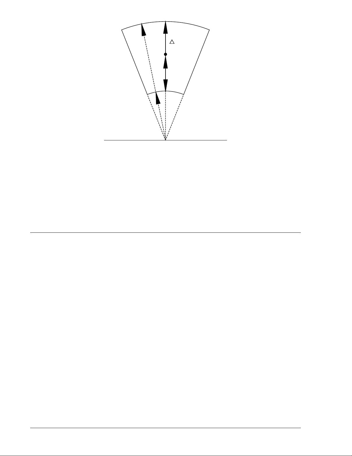
Figure 1-5. Closing Zone Diagram (Average Sensing)
Output Relay
The Voltage Monitor output relay option G or H provides additional supervision of the breaker closing
circuit, or provides an indication of the existing voltage conditions for the supervisory control system.
When a Voltage Monitor output relay is installed, the SYNC relay is no longer directly operable by voltage
monitor logic. However, the live line/live bus condition may be utilized to enable the Sync-Check function.
Detailed instructions and precautions for setting the Mode switches and Condition switches are provided
in Table 2-1, callouts R and S. The location of the switches is shown in Figure 2-2.
Voltage sensing connections are shown in Figure 4-9.
OTHER OPTIONS
Expandable Window
An expandable window (option 9 in the second position of the Style Number) is available to enable a local
operator (through a switch) or a remote dispatcher (through the supervisory control system) to expand the
preset phase angle window by a programmed ratio.
Under normal conditions, the phase angle setting is determined by the maximum angular difference that
has been calculated as suitable to meet the expected load flow of the total system. However, under
emergency conditions, the load flow throughout the system may result in excessive phase angle
separation across the opened breaker.
In order to reestablish load on a previously faulted line quickly, it may be necessary to expand the
allowable phase window. With this option, closing a contact input to the relay expands the preset phase
setting by a programmed multiple of 2 or 3 (according to the position of a jumper on the circuit card).
This option is not suggested for use in generator applications for the following reason: The phase angle
setting for a generator breaker is determined by the maximum phase difference that can be tolerated by
the generator when connected to the system. An excessive angle can result in excessive mechanical
forces in the generator and associated mountings.
Internal connections for the expandable window are shown in Figure 4-8; control circuit connections are in
Figures 4-11 and 4-12.
External Condition Switches
If a line and bus Voltage Monitor output is incorporated in the relay, the internal Condition Switches may
be functionally operated by remotely located external contacts. This capability is provided by Voltage
Monitor option 2-C, 2-U, or 2-V, but requires a voltage dropping Resistor Module to be mounted on the
relay back panel (see Figure 4-10).
V
P0004-39
V
B
L
V
1-6 BE1-25 General Information 9170200990 Rev U

Push-to-Energize Output Pushbuttons
Two PUSH-TO-ENERGIZE OUTPUT switches are available to provide a means of verifying external
output wiring without the inconvenience of having to test the entire relay. These optional switches are
provided for each isolated output function (Sync-Check, Auxiliary Sync-Check and Voltage Monitor), and
may be actuated by inserting a thin, non-conducting rod through access holes in the front panel. See
Figure 2-1 for location.
MODEL AND STYLE NUMBER
The electrical characteristics and operational features of the BE1-25 Sync-Check Relays are defined by a
combination of letters and numbers that make up its Style Number. The model number, together with the
Style Number, describes the options included in a specific device, and appears on the front panel,
drawout cradle, and inside the case assembly.
Upon receipt of a relay, be sure to check the Style Number against the requisition and the packing list to
ensure that they agree.
Style Number Example
The Style Number identification chart (Figure 1-6) defines the electrical characteristics and operational
features included in BE1-25 relays. For example, if the Style Number were M9H-A6P-N4R0F, the device
would have the following:
BE1-25 Model Number (designates the relay as a Basler Electric, Class 100, Sync-Check Relay)
M Single-phase sensing
9 Expandable phase angle window
H Voltage Monitor relay and Push-to-Energize outputs
A6 0.1 to 99 seconds timing range
P Operating power derived from 125 Vdc or 120 Vac
N No target
4 Non-isolated contact sensing input
R Line and Bus Voltage Monitor; also a Voltage Difference Monitor with Condition Switches
internal to the relay.
0 No auxiliary output
F Semi-flush mounting
9170200990 Rev U BE1-25 General Information 1-7
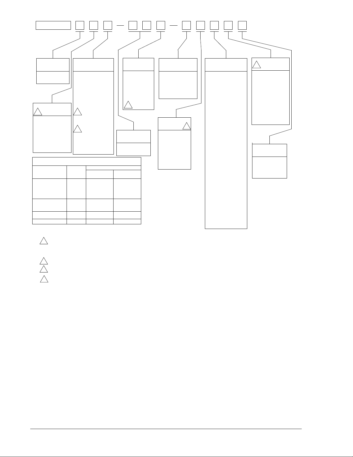
Figure 1-6. Style Number Identification Chart
OPTION 3
OPTION 4
OPTION 2
OPTION 1
SUPPLY
RANGE
SENSING INPUT
M
POWER
BE1-25
MODEL NO.
SENSING INPUT
TYPE
M) Single Phase
Voltage
OUTPUT
TIMING
TARGET
N) None
A) One Internally
Operated
B) One Current
Operated
F) Semi-Flush
Mounting
P) Projection
Mounting
1) 120 Vac, 1-99°
Phase Angle
Setting
9) 120 Vac, 1-99°
Phase Angle
Setting With
Expandable
Window
1
E) Sync-Check
NO Relay
F) Sync-Check
NO Relay with
Push-to-
Energize
Output
G) Sync-Check
NO Relay and
Voltage Monitor
SPDT Relay
H) Sync-Check
NO Relay and
Voltage Monitor
SPDT Relay
with Push-to-
Energize
Output (for
both relays)
4
4
A6) 0.1-99 Sec.
A7) 1-99 Cycles
O) 48 Vdc
P) 125 Vdc or
100/120
Vac
R) 24 Vdc
T) 250 Vdc or
240 Vac
3
4) Non-Isolated
Contact
Sensing
Input
5) Isolated
Contact
Sensing
Input
N) None
R) Line and Bus
Voltage Monitor
and Voltage
Difference with
PC Bd Mounted
Switches
S) Line and Bus
Voltage Monitor
with PC Bd
Mounted Switches
T) Voltage Difference
Voltage Monitor
and Voltage
Difference with
External Contact
Inputs
V) Line and Bus
Voltage Monitor
with External
Contact Inputs
0) None
1) Sync-Check
Auxiliary Output
NO Relay
2) Sync-Check
Auxiliary Output
NC Relay
3) Sync-Check
Auxiliary Output
SPDT Relay
6) Power Supply
Status Output
1
CONTACT SENSING MODULES
(Required when Type T Power Supply is specified)
Module Ordering Number
9 1702 06 106
Non-Isolated
Contact Sensing
Isolated
Contact Sensing
Number of
Contacts
Sensed
Relay Options
Voltage Monitor
with External
Contact Inputs
plus Expandable
Phase Window
Voltage Monitor
with External
Contact Inputs
Expandable Phase
Window
None of the above
9 1702 06 100
9 1702 06 101 9 1702 06 107
9 1702 06 104 9 1702 06 110
9 1702 06 105 9 1702 06 111
6
5
2
1
NOTES:
When Sensing Input Range 9 is Selected from the
Style Chart, Option 3 must be 0.
All relays are supplied in an S1 size case.
Requires Contact Sensing Module. See Table in this chart.
Not available if Option 2 is B, N, or T.
1
3
4
2.
D434-006.vsd
01-30-01
A) Average
Voltage Monitor
and Voltage
Difference with
PC Bd Mounted
Switches
U) Line and Bus
C) Average
B) Average Voltage
Difference
Voltage Monitor
and Voltage
Difference with
External Contact
Inputs
For more information on contact sensing see Specifications.
5
5
1-8 BE1-25 General Information 9170200990 Rev U
SPECIFICATIONS
Voltage and Phase Sensing
Nominally rated at 60 hertz with a range of 45 to 65 hertz at a
maximum burden of 1 VA per phase to 125% of nominal voltage.
Maximum continuous voltage rating is 160% of nominal.
Contact Sensing
User-supplied contacts with a minimum rating of 0.05 ampere at
250 Vdc are required at all contact sensing inputs. (Specifically the
52b input, the optional expandable phase angle window, and the
optional external voltage condition switches.)
Sensing circuit current is supplied by the relay when isolated
sensing is selected. Non-isolated sensing requires an externally
applied dc sensing voltage equal to the nominal voltage of the
relay power supply input.
Contact Sensing Burden
For Power Supply Option O ...... 2.4 VA
For Power Supply Option P ....... 6.25 VA
For Power Supply Option R ....... 1.2 VA
For Power Supply Option T…….12.5 VA
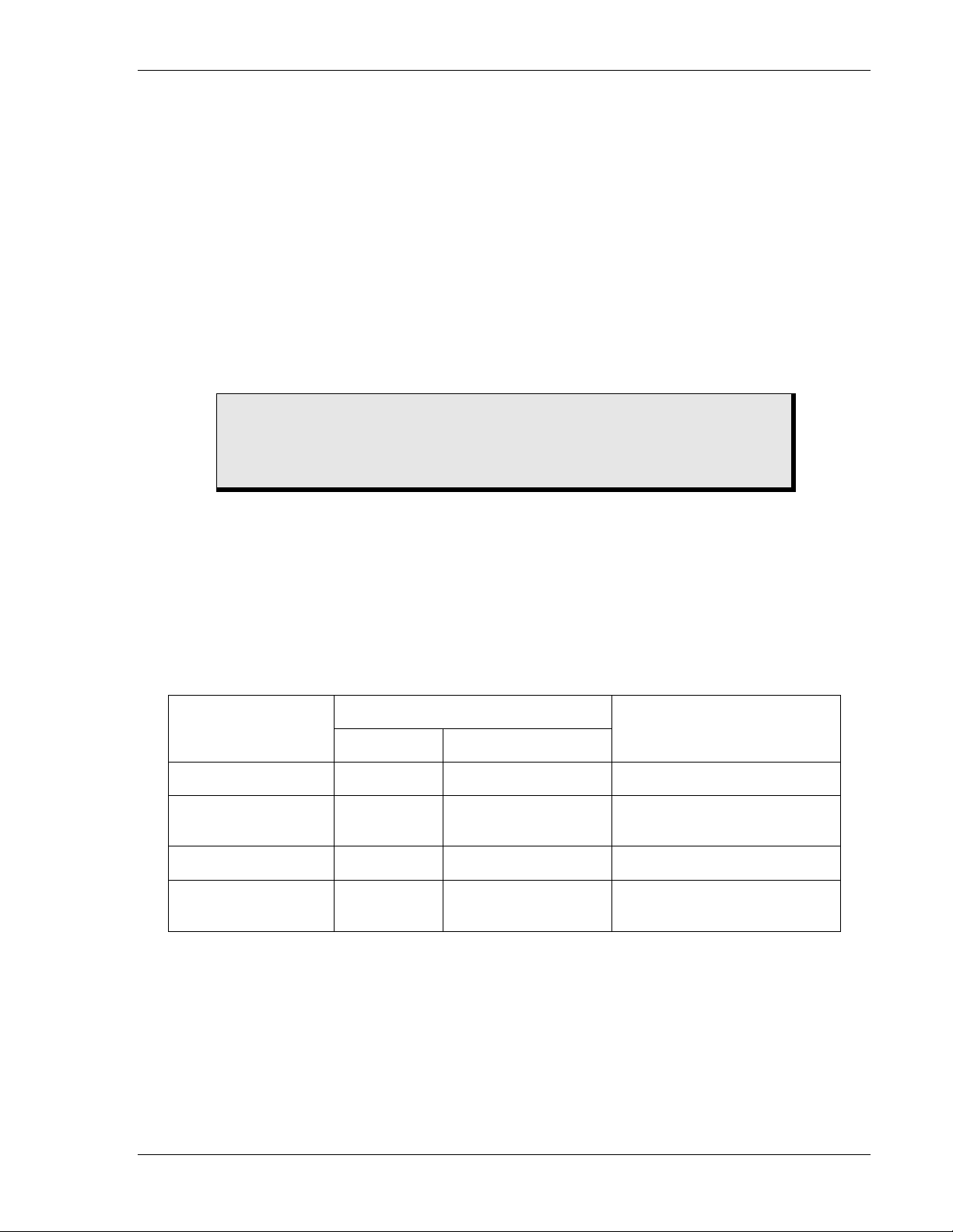
Power Supply
One of the four types of power supplies listed in Table 1-1
may be
selected to provide internal relay operating power.
Table 1-1. Power Supply
Type
Input Voltage
Burden at Nominal
Nominal Range
O (mid range) 48 Vdc 24 to 150 Vdc 1.5 W
P (mid range)
125 Vdc
120 Vac
24 to 150 Vdc
90 to 132 Vac
1.8 W
10.5 VA
R (low range) 24 Vdc
12 to 32 Vdc ∗
1.6 W
T (high range)
250 Vdc
240 Vac
68 to 280 Vdc
90 to 270 Vac
2.1 W
17.4 VA
∗ Type R power supply may require 14 Vdc to begin operation. Once operating, the voltage may be
reduced to 12 Vdc.
CAUTION
If contact sensing is isolated (style number Mxxxxxx5xxx), external voltage
should not be applied to the contact sensing inputs. Applying voltage to the
contact sensing inputs will result in damage to the relay.
9170200990 Rev U BE1-25 General Information 1-9

Output Contacts
Output contacts are rated as follows:
Resistive
120 Vac
Make, break, and carry 7 Aac continuously.
250 Vdc
Make and carry 30 Adc for 0.2 seconds, carry 7 Adc continuously,
break 0.3 Adc.
500 Vdc
Make and carry 15Adc for 0.2 s, carry 7 Adc continuously, break
0.3 Adc
Inductive
120 Vac, 125 Vdc,
250 Vdc
Break 0.3 A, (L/R = 0.04).
Target Indicator
The target indicator may be either internally operated or current
operated (operated by a minimum of 0.2 A through the output trip
circuit). When the target is current operated, the sync output circuit
must be limited to 30 A for 1 second, 7 A for 2 minutes, and 3 A
continuously.
Phase Angle
Selection Accuracy
± 0.5° or ± 5.0% of the front panel setting for degrees, whichever is
greater, for a nominal input frequency of 50/60 hertz, a sensing
input range of 80 to 135 volts, and at 25
°
C.
Setpoint Accuracy
±0.5° or ±5%, whichever is greater, from a reference measurement
at 25°C, at nominal input frequency and levels, over the specified
operating range of temperature and input voltages.
Timing Accuracy at 25°C
Maximum of 25 milliseconds or 5% of the front panel setting for
time whichever is greater, for a nominal input frequency of 50/60
hertz at 25°C.
TIME Delay Accuracy
(Overall)
±10 milliseconds or ±2%, whichever is greater, of the time delay at
25°C, over the full temperature, voltage, and frequency ranges.
Minimum Voltage
Requirement
Minimum voltage detection circuitry enables the sync-check
circuitry when both line and bus are within operating range of the
relay. Voltage sensing circuits are guaranteed to operate at a
minimum voltage of 60 volts. They are guaranteed not to operate
at voltages less than 20 volts. Some units may operate at voltages
in between these two levels because of the individual
characteristics of specific components. Minimum voltage detection
is usually in the range of 45 to 55 volts.
Voltage Difference Option
Range
Continuously adjustable over the range of 1 to 135 Vac.
Accuracy Voltage difference setpoint does not vary more than 0.5 V or 5%,
whichever is greater, from a reference measurement at 25°C, with
nominal input frequency, and variation of temperature or voltage
inputs over their specified operating range. This setpoint does not
vary more than 3% from a reading at 25°C over the limited range
of +15 to +40°C.
1-10 BE1-25 General Information 9170200990 Rev U
Loading...