


 Loading...
INSTRUCTION MANUAL
FOR
BE1-11 Protection Systems
IEC 61850 Protocol
Publication: 9424200892
Revision: F Sep-14
9424200892 Rev F |
i |
Preface
This instruction manual provides detailed information about BE1-11 Protection Systems with the IEC 61850 Protocol. To accomplish this, the following information is provided:
•IEC 61850 engineering
•Logic inputs and outputs configuration
•Operation of BEST61850 software
•File transfer
•Data tags
•Conformance Statements
Conventions Used in this Manual
Important safety and procedural information is emphasized and presented in this manual through Warning, Caution, and Note boxes. Each type is illustrated and defined as follows.
Warning!
Warning boxes call attention to conditions or actions that may cause personal injury or death.
Caution
Caution boxes call attention to operating conditions that may lead to equipment or property damage.
Note
Note boxes emphasize important information pertaining to installation or operation.
BE1-11 |
Preface |

ii |
9424200892 Rev F |
12570 State Route 143
Highland IL 62249-1074 USA
www.basler.com
info@basler.com
Tel: +1 618.654.2341
Fax: +1 618.654.2351
© 2014 by Basler Electric All rights reserved
First printing: October 2010
Warning!
READ THIS MANUAL. Read this manual before installing, operating, or maintaining the BE1-11. Note all warnings, cautions, and notes in this manual as well as on the product. Keep this manual with the product for reference. Only qualified personnel should install, operate, or service this system. Failure to follow warning and cautionary labels may result in personal injury or property damage. Exercise caution at all times.
Basler Electric does not assume any responsibility to compliance or noncompliance with national code, local code, or any other applicable code. This manual serves as reference material that must be well understood prior to installation, operation, or maintenance.
For terms of service relating to this product and software, see the Commercial Terms of Products and Services document available at www.basler.com/terms.
This publication contains confidential information of Basler Electric Company, an Illinois corporation. It is loaned for confidential use, subject to return on request, and with the mutual understanding that it will not be used in any manner detrimental to the interests of Basler Electric Company and used strictly for the purpose intended.
It is not the intention of this manual to cover all details and variations in equipment, nor does this manual provide data for every possible contingency regarding installation or operation. The availability and design of all features and options are subject to modification without notice. Over time, improvements and revisions may be made to this publication. Before performing any of the following procedures, contact Basler Electric for the latest revision of this manual.
The English-language version of this manual serves as the only approved manual version.
Preface |
BE1-11 |

9424200892 Rev F |
iii |
Contents |
|
General Information .................................................................................................................................... |
1 |
IEC 61850 Configuration ........................................................................................................................... |
2 |
IEC 61850 Standard .............................................................................................................................. |
2 |
BESTCOMSPlus® .................................................................................................................................. |
2 |
BEST61850™ ......................................................................................................................................... |
3 |
References ................................................................................................................................................ |
3 |
IEC 61850 Engineering ............................................................................................................................... |
5 |
Engineering Process in IEC 61850 ........................................................................................................... |
5 |
System Configurator .............................................................................................................................. |
5 |
IED Configurator Tool (BEST61850™)................................................................................................... |
6 |
ICD File (IED Capability Description File).............................................................................................. |
6 |
SSD File (System Specification Description File).................................................................................. |
6 |
SCD File (Substation Configuration Description File)............................................................................ |
6 |
CID File (Configured IED Description File)............................................................................................ |
6 |
SCL Object Model ..................................................................................................................................... |
6 |
Substation Configuration Description Language (SCL) ............................................................................ |
8 |
Signal Identification.............................................................................................................................. |
10 |
IED Related Naming ............................................................................................................................ |
10 |
Communication Network Section......................................................................................................... |
11 |
IED Section .......................................................................................................................................... |
12 |
Signal Engineering............................................................................................................................... |
14 |
BESTCOMSPlus® ...................................................................................................................................... |
17 |
CTLGGIO OPER Output and INDGGIO OPER Input ............................................................................. |
17 |
CTLGGIO OPER Alarm........................................................................................................................... |
17 |
IEC61850PTRC Logic Block ................................................................................................................... |
17 |
BEST61850™ ............................................................................................................................................. |
19 |
Installation ............................................................................................................................................... |
19 |
Install BEST61850™............................................................................................................................. |
19 |
Menu Bar ................................................................................................................................................. |
20 |
BEST61850™ Settings............................................................................................................................. |
20 |
Device Info ........................................................................................................................................... |
20 |
Datasets............................................................................................................................................... |
21 |
Published IED GOOSE........................................................................................................................ |
23 |
Subscribed IED GOOSE...................................................................................................................... |
24 |
Report Controls.................................................................................................................................... |
25 |
File Viewer ........................................................................................................................................... |
27 |
Configuration Example ............................................................................................................................ |
28 |
Configure Communication Parameters and Names ............................................................................ |
28 |
Configure DataSets.............................................................................................................................. |
29 |
Configure Published IED GOOSE ....................................................................................................... |
31 |
Configure Subscribed IED GOOSE..................................................................................................... |
32 |
Configure Report Control Blocks ......................................................................................................... |
33 |
Save a CID File as a User Template ................................................................................................... |
36 |
Save a CID File.................................................................................................................................... |
37 |
Upload a CID File to the BE1-11 ......................................................................................................... |
38 |
Measurement Logic Node Configuration................................................................................................. |
38 |
File Transfer............................................................................................................................................... |
43 |
Data Tags ................................................................................................................................................... |
45 |
Conformance Statements......................................................................................................................... |
73 |
MICS........................................................................................................................................................ |
73 |
PICS ........................................................................................................................................................ |
75 |
PIXIT........................................................................................................................................................ |
80 |
BE1-11 |
Contents |

iv |
9424200892 Rev F |
TICS......................................................................................................................................................... |
86 |
Mandatory Intop Tissues ..................................................................................................................... |
86 |
Optional IntOp Tissues ........................................................................................................................ |
87 |
Revision History........................................................................................................................................ |
89 |
Contents |
BE1-11 |

9424200892 Rev F |
1 |
General Information
This document describes the Basler Electric IEC 61850 Protocol implementation in the BE1-11 series of protection systems. A BE1-11 is classified as an intelligent electronic device (IED) that is capable of sending and receiving IEC 61850 messages simultaneously.
The IEC 61850 protocol is an option available when ordering a BE1-11. An Ethernet connection is required for operation of IEC 61850.
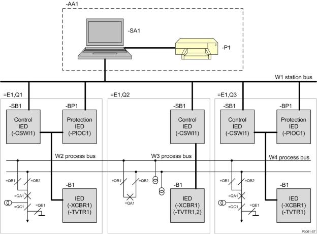
IEC 61850 is a communications infrastructure that allows seamless integration of IEDs into higher level devices. IEDs from different vendors can be integrated together in this vendor independent infrastructure. A typical station bus is illustrated in Figure 1.
Protection, control, and metering for the substation are defined in an SCL (Substation Configuration Language) file. The BE1-11 comes with an SCL compatible ICD (IED Capability Description) file that is uploaded to the BE1-11 as a CID (configured ICD) file. The substation design developer uses the CID file to create the portion of the SCD (Substation Configuration Description) file for the overall substation design.
Figure 1. Typical Station Bus
BE1-11 |
General Information |
2 |
9424200892 Rev F |
The BE1-11 is capable of transmitting the following items on an IEC 61850 network:
•Configuration Settings
•Metering
•Status
•Alarms
•Targets
•Breaker Operations
•Direct Control
•Fault Records
•Load Profile
•Oscillographic Records
•Sequence of Events Reports
•Unsolicited Reports
•Peer to Peer Control GOOSE
•Device Discovery
IEC 61850 Configuration
IEC 61850 Standard
The IEC 61850 standard defines the parts for communicating information between IEDs in a substation. Figure 2 illustrates the Basler IEC 61850 configuration process.
|
|
|
|
|
|
Basler |
|
|
|
|
|
|
|
||
Substation |
|
|
SCD file |
|
|
BEST61850 |
|
Configuration Tool |
|
|
|
|
Validate SCL |
||
|
|
|
|
|
|||
|
|
|
|
|
|
||
|
|
|
|
|
|
and Map GOOSE |
|
|
|
|
|
|
|
||
|
|
|
|
|
|
|
|
|
|
|
|
|
|
|
Upload SCL |
|
|
|
|
|
|
|
(CID file) |
|
|
|
|
|
|
|
|
Basler |
|
|
|
|
|
|
|
BESTCOMSPlus® |
|
Upload settings |
Basler |
||||
Create relay settings BSTX file |
|
|
|
|
|
BE1-11 System |
|
|
|
|
|
|
|
|
|
|
|
|
|
|
|
|
|
Figure 2. Basler IEC 61850 Configuration Process
P0061-44
BESTCOMSPlus®
BESTCOMSPlus software is provided with the BE1-11. Refer to the BESTCOMSPlus chapter for more information.
BESTCOMSPlus performs the following tasks:
•Maps BE1-11 inputs and outputs to IEC 61850 data points that can be read directly with an IEC 61850 browser
•Uses a point-and-click method to configure BE1-11 settings and logic
•Uploads and downloads BE1-11 settings files
•Provides metering and reports from the BE1-11
General Information |
BE1-11 |

9424200892 Rev F |
3 |
BEST61850™
BEST61850 software is provided with the BE1-11. Refer to the BEST61850 chapter for more information. BEST61850 performs the following functions:
•Imports an SCD file and extracts the necessary information for each IED in the system
•Maps subscribed GOOSE messages between devices
•Configures published GOOSE messages
•Configures DataSets
•Configures Report Control Blocks (RCB)
•Creates a CID file and uploads it to the IED or exports it to a file
•Performs any additional engineering operations
References
•BE1-11f, Feeder Protection System, Publication 9424200990
•BE1-11g, Generator Protection System, Publication 9424200994
•BE1-11i, Intertie Protection System, Publication 9424200993
•BE1-11m, Motor Protection System, Publication 9424200996
•BE1-11t, Transformer Protection System, Publication 9424200995
•IEC 61850: Communication networks and systems in substations (See Table 1)
|
Table 1. Parts to IEC 61850 |
Part |
Title |
|
|
1 |
Introduction and overview |
|
|
2 |
Glossary |
|
|
3 |
General requirements |
|
|
4 |
System and project management |
|
|
5 |
Communication requirements for functions and device models |
|
|
6 |
Configuration description language for communication in electrical substations related to IEDs |
|
|
7-1 |
Basic communication structure for substation and feeder equipment − Principles and models |
|
|
7-2 |
Basic communication structure for substation and feeder equipment − Abstract communication |
|
service interface (ACSI) |
|
|
7-3 |
Basic communication structure for substation and feeder equipment − Common data classes |
|
|
7-4 |
Basic communication structure for substation and feeder equipment − Compatible logical node |
|
classes and data classes |
|
|
8-1 |
Specific Communication Service Mapping (SCSM) − Mappings to MMS (ISO 9506-1 and ISO |
|
9506-2) and to ISO/IEC 8802-3 |
|
|
9-1 |
Specific Communication Service Mapping (SCSM) − Sampled values over serial unidirectional |
|
multidrop point to point link |
|
|
9-2 |
Specific Communication Service Mapping (SCSM) − Sampled values over ISO/IEC 8802-3 |
|
|
10 |
Conformance testing |
|
|
BE1-11 |
General Information |

4 |
9424200892 Rev F |
General Information |
BE1-11 |
9424200892 Rev F |
5 |
IEC 61850 Engineering
The engineering process and configuration of a substation is described in IEC 61850-Part 6:
Configuration description language for communication in electrical substations related to IEDs.
This section contains information about the standard that may be referenced when working with BESTCOMSPlus® and BEST61850™ software.
Engineering Process in IEC 61850
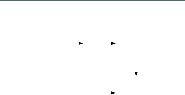
Figure 3 illustrates the reference model for information flow in the configuration process.
|
IED Capabilities |
|
|
System Specification |
|
|
|
||
IED |
ICD File |
System |
|
SSD File |
|
|
|
||
Database |
|
Configurator |
|
|
|
|
|
|
|
|
|
Substation Configuration |
||
|
|
SCD File |
|
|
|
|
|
|
|
|
|
IED |
|
|
|
|
Configurator |
|
|
|
|
|
|
|
|
|
Configured IED |
||
|
Engineering Environment |
CID File |
|
|
Substation |
|
|
|
|
|
|
|
File transfers and parameterization |
|
Local file transfer |
Substation |
|||
Gateway |
with IEC 61850 services |
|||
|
||||
|
|
|
|
|
|
|
|
|
|
IED |
IED |
IED |
P0061-56
Figure 3. Reference Model for Information Flow in the Configuration Process
The IEC 61850 standard defines two tools and four file types for Engineering as illustrated in Figure 3. The tools and file types are defined below.
System Configurator
The System Configurator performs the following functions:
•Imports and exports configuration files
•Imports configuration files from several IEDs for system level engineering
•Generates a substation related configuration file
•Reads an SSD file as a base for starting system engineering or for comparisons
The complete station configuration is exported in the SCD file for further use by the various IED configuration tools.
BE1-11 |
IEC 61850 Engineering |

6 |
9424200892 Rev F |
IED Configurator Tool (BEST61850™)
BEST61850 performs the following functions:
•Imports an SCD file and extracts the necessary information for each IED in the system
•Maps subscribed GOOSE messages between devices
•Configures published GOOSE messages
•Configures DataSets
•Configures Report Control Blocks (RCB)
•Creates a CID file and uploads it to the IED or exports it to a file
•Performs any additional engineering operations
ICD File (IED Capability Description File)
The capabilities of an IED are described in this file. The file contains logical node type definitions and may contain an optional substation section.
SSD File (System Specification Description File)
This file describes the single line diagram of the substation and the required logical nodes. It contains a substation description section and the data templates and logical node definitions.
SCD File (Substation Configuration Description File)
This file contains the data exchanged from the system configuration tool to the IED configuration tool. It contains all IEDs, a communication configuration section, and a substation description.
CID File (Configured IED Description File)
This file contains the data exchanged from the IED configuration tool to the IED.
SCL Object Model
The SCL (Substation Configuration Language) object model consists of the following parts:
•The primary (power) system structure
•The communications system
•The application level communication
•Each IED
•Instantiable logical node (LN) type definitions
•The relations between instantiated logical nodes and their hosting IEDs on one side and the switchyard (function) parts on the other side
Figure 4 shows an instance of the SCL object model: a simple example of an SA (Substation Architecture) system used for a switchyard. The switchyard has a 110 kV voltage level E1. It is a double bus bar system with two line bays =E1Q1 and =E1Q3, and a bus coupler =E1Q2. The IEDs are already assigned to switchyard functionality (for example the bay controller –E1Q1SB1 as a product is assigned to bay =E1Q1, and its Logic Node CSWI1 controls the circuit breaker =E1Q1QA1 via the Logic Node XCBR1 on the IED –E1Q1QA1B1). Figure 4 uses a – (minus) sign to indicate the product-related designations. The functional name is not repeated. The station level communication sub network is named W1. There are three additional sub networks at process level (W2, W3, and W4).
IEC 61850 Engineering |
BE1-11 |
9424200892 Rev F |
7 |
Figure 4. Configuration Example (from IEC 61850-6)
The IEC 61850 standard is based on the hierarchical addressing and information model in a station. It follows, in this way, the structure of the substation equipment independent of IED structure and organization. This information and addressing model is also visible in the IEC 61850 telegrams because the address is presented in MMS (Manufacturing Message Specification) as an ASCII string, so the address can be seen directly in a readable form.
The IEC 61850 standard defines the information and its exchange in a way that it is independent of a concrete implementation (i.e., it uses abstract models). The standard also uses the concept of virtualization. Virtualization provides a view of those aspects of a real device that are of interest for the information exchange with other devices. Only those details that are required to provide interoperability of devices are defined in the IEC 61850 standard.
The approach of the standard is to decompose the application functions into the smallest entities, which are used to exchange information. These entities are called logical nodes (for example, a virtual representation of a circuit breaker class, with the standardized class name XCBR). Several logical nodes build a logical device (for example, a representation of a Bay unit). A logical device is always implemented in one IED; therefore logical devices are not distributed.
Real devices on the right-hand side of Figure 5 are modeled as a virtual model in the middle of the figure. The logical nodes defined in the logical device (for example, Bay) correspond to well-known functions in the real devices. In this example, the logical node XCBR represents a specific circuit breaker of the bay to the right.
BE1-11 |
IEC 61850 Engineering |

8 |
9424200892 Rev F |
Figure 5. Modeling Approach Example
Substation Configuration Description Language (SCL)
The SCL language is based on XML (Extensible Markup Language). Detailed knowledge about an XML file is not required, but the information within the file may be of interest. An SCL XML file is divided into the following five sections as specified in IEC 61850-6:
•Header
•Substation description
•Communication system description
•IED description
•Data Type Templates
The Header identifies an SCL configuration file and version, and specifies options for the mapping of names to signals. The Substation section describes the functional structure of a substation, and defines the primary devices and their electrical connections.
Default ICD files in BEST61850 software are used to define the Header and Substation description sections. Logical nodes of the IED are logically linked to the substation section. BEST61850 software is used for signal engineering and routing of the signals. BESTCOMSPlus must be used to define the substation and communication sections prior to using BEST61850. BEST61850 is used to configure the DataSets and Control Blocks that are located in the IED section. The DataSets and Control Blocks (Report, GOOSE, and Setting) are logically defined as part of the logical nodes per IEC 61850-7-2. GOOSE engineering requires that BEST61850 has the correct configured Communication description section. The Data Type Templates section gives the correct content description of each logical node type to the clients. Logical node type definitions may vary between each IED and vendor.
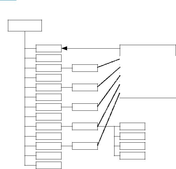
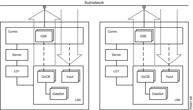
Figure 6 shows the principle structure of the SCL XML file. The arrows show the link between the different sections given when an IED is integrated in the substation structure and/or in the communication structure. All available logical nodes of an IED are linked to the substation section.
A reference to the GoCB (GOOSE Control Block) is included in the communication section when the GoCB is configured. The graphical presentation of the XML file is a standard view of XML editors. It gives a better picture about the structure of the XML contents.
IEC 61850 Engineering |
BE1-11 |

9424200892 Rev F |
|
|
|
9 |
|
Header |
|
|
|
|
Header |
id |
|
|
|
|
|
toolID |
|
|
|
|
|
nameStructure |
|
|
|
||
|
|
|
|
||
Substation |
|
|
|
|
|
Voltage Level |
|
|
|
|
|
|
Bay |
|
|
|
|
|
LNode |
|
|
|
|
|
IED |
|
LD |
LN |
Station |
|
IED |
|
LD |
LN |
|
Communication |
|
|
|
|
|
|
|
|
|
|
|
Subnetwork |
|
|
|
|
|
|
ConnectedAP |
|
|
|
|
|
IED Name |
AccessPoint |
Address |
|
GSE |
|
IED Name |
AccessPoint |
Address |
|
GSE |
IED |
|
|
|
|
|
Services |
AccessPoint |
|
|
|
|
|
Server |
|
|
|
|
|
Authentication |
|
|
|
|
|
LDevice |
|
|
|
|
|
|
LN0 |
|
LN |
|
|
|
DataSet |
|
DOI |
|
|
|
|
|
|
DAI |
|
|
Report Control |
|
|
|
|
|
GOOSE Control |
|
|
|
|
|
Inputs |
|
|
|
|
|
DOI |
|
|
|
|
|
Setting Control |
|
IED |
|
DataTypeTemplates |
|
|
|
|
|
|
|
|
|
|
|
LNodeType |
|
|
|
|
|
|
DO |
|
|
|
|
|
DOType |
|
|
|
|
DOType |
|
|
|
|
|
DA |
SDO |
DAType |
DAType
|
BDA |
|
|
EnumType |
|
EnumType |
-69 |
|
P0061 |
||
|
Figure 6. Principle Structure of the SCL XML File
BE1-11 |
IEC 61850 Engineering |

10 |
9424200892 Rev F |
Signal Identification
Elements of the signal identification as defined in IEC 61850–7–2 are illustrated in Figure 7.
|
Part 1 |
|
|
|
Part 2 |
|
|
|
|
|
|
|
Part 3 |
|
|
|
Part 4 |
|
|
|||
|
|
|
|
|
|
|
|
|
|
|
|
|
|
|
|
|||||||
|
|
|
|
|
|
|
|
|
|
|
|
|
|
|
|
|
|
|
|
|
|
|
|
|
|
|
|
|
|
|
|
|
|
|
|
|
|
|
|
|
|
|
|
|
|
LDName |
|
|
|
|
|
|
|
LNName |
|
|
|
|
Data Name |
Data Attribute Name |
|
|||||||
|
|
|
|
|
|
|
|
|
|
|
|
|
|
|
|
|||||||
LN Prefix |
|
|
LN Class |
|
LN Instance # |
|
||||||||||||||||
|
|
|
|
|
|
|
|
|
|
|
||||||||||||
|
|
|
|
|
|
|
|
|
|
|
|
|
|
|
|
|
|
|
|
|
|
|
|
|
|
|
|
|
|
|
|
|
|
|
|
|
|
|
|
|
|
|
|
P0061-62 |
|
|
|
|
|
|
|
|
|
|
|
|
|
|
|
|
|
|
|
|
|
|
||
|
|
|
|
|
|
|
|
|
|
|
|
|
|
|
|
|
|
|
|
|
|
|
|
|
|
|
|
Configurable |
|
|
Defined in IEC |
|
Defined in IEC |
|
|
|
|||||||||
|
|
|
|
|
|
|
|
|
61850-7-4 |
|
61850-7-3 |
|
|
|
|
|||||||
|
|
|
|
|
|
|
|
|
|
|
|
|
|
|
|
|
|
|
||||
|
|
|
|
|
|
|
|
|
|
|
|
|
|
|
|
|
|
|
|
|
|
|
|
|
|
|
|
|
|
|
|
|
|
|
|
|
|
|
|
|
|
|
|||
BE1_11PRO |
|
|
|
|
|
|
|
LNName |
|
|
|
|
Ind01 |
|
stVal |
|
||||||
|
|
|
|
|
|
|
|
|
|
|
|
|
|
|
|
|
||||||
|
|
IND |
|
|
GGIO |
|
1 |
|
|
|
||||||||||||
|
|
|
|
|
|
|
|
|
|
|
|
|
|
|||||||||
|
|
|
|
|
|
|
|
|
|
|
|
|
|
|
|
|
|
|
|
|
|
|
BE1-11 XML Example: BE1_11PRO.INDGGIO1$Ind01$stVal
Figure 7. Elements of the Signal Identification as Defined in IEC 61850-7-2
The signal designation consists of the following four parts:
1.A user defined part identifying the Logical Device LD in the process (LDName).
2.A function related part to distinguish several LNs of the same class within the same LD/IED (LNPrefix).
3.The standardized LN class name and the LN instance number, which distinguishes several LNs of the same class and prefix within the same LD/IED.
4.A signal identification inside a LN consisting of data and attribute name as defined in IEC 61850– 7–3 and IEC 61850–7–4.
IED Related Naming
The LDName part is built out of the objects IED and LDevice. The LNName is the LN Prefix, the LN class and the LN instance #.
The LN prefix is used to identify several versions of a LN class. The link between the IED and the primary process (Substation, Voltage level, Bay) is given in the substation section of the station SCD file but not in the signal identification in the telegram. The IED name may be extended with a short form of the three missing levels. See Figure 8.
IEC 61850 Engineering |
BE1-11 |

9424200892 Rev F |
11 |
P0061-63
|
LDName |
|
|
LNName |
|
|
|
|
||
|
|
|
|
|
|
|
|
|
||
|
LN Prefix |
LN Class |
LN Instance # |
|
||||||
|
|
|
|
|||||||
|
|
|
|
|
|
|
|
|
|
|
|
|
|
|
|
|
|
|
|
IED Section: |
|
|
|
|
|
|
|
|
|
|
Attribute Inst of element LN |
|
|
|
|
|
|
|
|
|
|
Defined in IEC 61850-7-4 |
|
|
|
|
|
|
|
|
|
|
||
|
|
|
|
|
|
|
|
|
Predefined by IED |
|
IED Section: |
IED Section: |
|
|
|
|
|
|
|
||
Attribute Name of |
Attribute Inst of |
|
Header: |
|
|
|
|
|||
element IED |
element LDevice |
|
NameStructure=”IEDName” |
|||||||
|
|
|
|
|
|
|
|
|
|
|
Figure 8. Elements of the Signal Name Using Product Naming
Figure 9 shows an example of an IED (SB1) with logical devices LD1 and LD2. Each logical device (LD1 and LD2) contain logical nodes LN1 and LN2, which control a circuit breaker QA1 of bay Q1 in voltage level E1.
Voltage Level
Bay
IED
Access Point
Station Bus
 E1
E1
 Q1
Q1
QA1
 SB1
SB1
LN1 |
LN2 |
LN1 |
LN2 |
|
LD1 |
|
LD2 |
 S1
S1
P0061-64
In the communication |
|
In the IED structure, this LD |
structure, this connection is |
|
|
|
is identified as -E1Q1SB1LD2. |
|
identified as W1E1Q1SB1S1. |
|
|
|
|
W1
Figure 9. Names within Different Structures of the Object Model
In the substation structure, this CBR is identified as
=E1Q1QA1.
In the substation structure, this LN is identified as
=E1Q1LD2QA1CSWI2.
In the IED (product) structure, this LN is identified as -E1Q1SB1LD2CSWI2.
Communication Network Section
The organization of the physical IEDs to the communication network is independent of the substation structure. The IEC 61850 standard defines the communication network with no relation to an existing media and protocol. The first mapping to an existing media and protocol is done in IEC 61850–8–1 with:
•Ethernet as medium
•MMS (Manufacturing Message Specification) protocol as defined in ISO 9506–1 and ISO 9506–2
The IEC 61850 standard describes in part 7–2 the Abstract Communication Service Interface (ACSI) in a media and protocol independent form. Part 8–1 specifies the mapping of this ACSI to the existing MMS.
The communication section in the SCL file describes the minimum of what is needed to identify how information is routed between the IEDs in a project. This is:
•the used sub networks
•the IEDs connected to the different sub networks
BE1-11 |
IEC 61850 Engineering |

12 |
9424200892 Rev F |
•the access points per IED to the sub networks
•the address
•the IP address of the LAN network is an exception also part of the address elements
•extended during signal engineering and routing, the link to the GoCB message in transmission direction
Figure 10 shows the IEC 61850-6: Communication Network.
IED (client)
-Access Point (AP)
-Address
-GSE: GoCBs
IED (client)
-Access Point (AP)
-Address
-GSE: GoCBs
IED (server) |
|
IED (server) |
|
|
|
Subnetwork |
AP |
|
 AP
AP
IED (client) |
|
|
IED (client) |
|
IED (client) |
|
|
|
|
|
|
- Access Point (AP) |
|
|
- Access Point (AP) |
|
- Access Point (AP) |
|
|
|
|||
- Address |
|
|
- Address |
|
- Address |
- GSE: GoCBs |
|
|
- GSE: GoCBs |
|
- GSE: GoCBs |
|
|
|
|
|
|
IED (server) |
|
|
IED (server) |
|
IED (server) |
|
|
|
|||
|
|
|
|
|
|
|
Figure 10. IEC 61850-6: Communication Network |
||||
P0061-65
IED Section
The IED section describes the complete IED as it is needed for IEC 61850 communication. The Data Type Template part of an IED may be seen as part of the IED, even when separated in its own section. The IED’s ICD file includes the description of the LNs, their Data Type Templates, and the used/supported services. The structure of the IED section follows the definitions made in the IEC 61850 standard.
Figure 11 illustrates organization of LDs, LNs, DOs, and DAs in an IED.
IEC 61850 Engineering |
BE1-11 |

9424200892 Rev F |
13 |
Figure 11. Organization of LDs, LNs, DOs, and DAs in an IED
An IED server represents the communication interface to the sub network (Ethernet).
•One or more Logical device(s) are connected to a server
•A set of Logical Nodes belong to a Logical Device
•The Logic Node LLN0 is a special Logic Node per Logic Device and contains the DataSets, GOOSE Control Blocks (GoCB), Report Control Blocks (RCB), and Setting Group Control Block (SGCB)
•The Logic Node LPHD is a special Logic Node per Logic Device and contains Data Objects (DO) which describe the status of the physical device (the IED)
•Each Logical Node represents a function and contains a number of Data Objects (DO)
•Each DO is represented by a number of Data Attributes (DA)
The data objects are representing information signals which may be routed to station level IEDs.
The signal engineering task is to select the requested signals (DOs) and link them to the client IEDs as receiver. The control services are not directly engineered. They are included in the data objects which handle both directions the command (control) and the response (monitoring). When routing the DO in monitoring direction the control is known by the clients. The organization of the IED from LD down to DAs can be viewed in the BEST61850 tool. This organization concept must be taken into consideration when DataSets are configured.
The number of data objects and data attributes per Logical Node is defined by the used LN type in this IED. The contents are taken from the Data Type Templates which belong to an IED type.
BE1-11 |
IEC 61850 Engineering |
14 |
9424200892 Rev F |
Signal Engineering
Signal engineering consists of DataSets, Report Control Blocks (RCB), and Goose Control Blocks (GoCB).
DataSets
IEC 61850 has defined DataSets for signal transmission in Report Control Blocks. DataSets are also used for GOOSE messages. Figure 12 shows a DataSet where all position information of the apparatuses of a bay are put into one DataSet.
LD1
|
|
|
DataSet |
|
LLN0 |
|
|
LD1/LLN0 |
|
|
|
|
||
LPHD |
|
LD1/SXCBR1.Pos FC=ST |
||
|
|
|||
SXCBR1 |
Pos |
LD1/SXSWI1.Pos FC=ST |
||
SCSWI1 |
|
LD1/SXSWI2.Pos FC=ST |
||
SXSWI1 |
Pos |
LD1/SXSWI3.Pos FC=ST |
||
|
|
|
||
SCSWI2 |
|
LD1/SXSWI4.Pos FC=ST |
||
|
|
|
|
|
SXSWI2 |
Pos |
|
|
|
SCSWI3 |
|
|
|
|
SXSWI3 |
Pos |
stVal |
|
|
SCSWI4 |
|
q |
|
|
SXSWI4 |
Pos |
t |
|
67 |
SCSWI5 |
|
Origin |
P0061- |
|
|
|
|||
CVMMXU1 |
|
|
|
|
Figure 12. DataSet Example
General rules for DataSet configuration:
•All data objects or their data attributes can be selected for a DataSet.
•Only those data attributes of a data object are selected which have the same functional constraint (FC).
•Data objects with different FC can be selected for a DataSet. For example DOs with FC=ST and DOs with FC=MX can be members in one DataSet.
•A single data attribute can be selected when it is specified with a trigger option. For example the data attribute stVal of the data object Pos can be selected as a member of a DataSet, because it is specified with the trigger option data change detected (dchg).
The description of the DataSets and the list of data object members or FCDAs (Functionally Constrained Data Attributes) is included in the SCL file in the IED section in the Logical Device subsection. FCDAs are
IEC 61850 Engineering |
BE1-11 |
9424200892 Rev F |
15 |
also referred to as Data Tags. As specified in IEC 61850–7–2 clause 9, the DataSets are part of a Logical Node. They are included in the LLN0.
Report Control Blocks (RCB)
The contents of an RCB are listed in IEC 61850– 7–2 in clause 14, table 23. The RCB contains a list of attributes which handle and secure the communication between the client and the server.
•Buffer Time - This parameter describes how long the report should wait for other expected events before it sends the report to the client. When known, additional events are generated as a follow up. It is useful to wait for approximately 500 ms for additional events stored in the report. This feature reduces the number of telegrams transmitted in case of a burst of changes. But it increases the overall transaction time for events from IED input to presentation on HMI which is normally one second.
•Trigger Options - Data attributes have three trigger options (dchg, qchg, dupd). Within the RCB, two others can be defined integrity and general interrogation. The attribute Trigger Option is a multiple choice and allows masking of the supported trigger options in this RCB.
•Integrity Period - When period is selected in the trigger option attribute, it is needed to define an integrity period to force the transmission of all data listed in the DataSet. This is done by the attribute Integrity Period. This feature can be used as a background cycle to ensure that the process image in all partners is the same.
•General Interrogation - A general interrogation is only done on request from a client. Not all DataSets contain information which is needed for a general update of the client. For example, data with T(ransient) = TRUE are not part of a GI. When the RCB attribute general interrogation is set to TRUE a GI request from the client will be handled. The report handler will transmit all data defined in the DataSet with their actual values. The IEC 61850 standard defines that all buffered events are transmitted first before the GI is started. A running GI is stopped and a new GI is started, when a new GI request is received while a GI is running.
Trigger Options
IEC 61850 has defined five different TrgOp. Three of them belong to data attributes and they are marked per data attribute in the column TrgOp of the CDC tables in part 7–3. The other two belong to the configuration of control blocks. The five trigger options are:
•dchg = data-change - The classical trigger. Whenever a process value has changed its value either binary or a measurement a transmission is done.
•qchg = quality change - Looking to the possibilities of the quality data attribute type (q) any changes in the quality description are transmitted.
•dupd = data value update - This trigger option gives the possibility to define that a transmission should be done on a condition which can be controlled by the application.
•Period - This trigger forces the transmission of all process values defined in the DataSet when a timer value (the integrity period) expires. For example, it can be used to do a process signal update in the background (e.g. every 15 minutes).
•General Interrogation - This trigger is forced by the clients (= station level IED; NCC gateway, station HMI, ...). Normally a GI is asked for when the client and the server start or restart a session. When the client is able to receive the actual values and when the Logical Device has scanned all process values at least once, an image of the actual process signal status can be transmitted to the client.
Goose Control Blocks (GoCB)
The Generic Object Oriented Substation Event (GOOSE) class model is used to distribute input and output data values between IEDs on bay level through the use of multicast services. GOOSE messages bypass the server which results in a fast transmission from publisher to one or several subscribers (receivers).
The GOOSE message concept is used for all application functions where two or more IEDs are involved.
BE1-11 |
IEC 61850 Engineering |
16 |
9424200892 Rev F |
To send GOOSE messages, a GoCB must be defined and a DataSet is needed which contains the data objects of single data attributes to be sent. A GOOSE message is forced to be transmitted when a trigger change is detected for a data attribute. All members of the DataSet will be copied in the send buffer with their actual value and the message is sent. All subscribers which know the address of this GOOSE message will receive the telegram. The GOOSE message includes a sequence number and a state number to verify that all messages are received.
In the SCL communication section in the GSE element, the GoCB is listed under the ConnectedAP.
The IEDs which should receive a GOOSE message are informed in the SCL private section that they will receive GOOSE messages. This is given when the external Reference, the name of the IED, and the member of the DataSet is included in the LLN0 logic node under the structure of the Logic Device (LD) of the receiving IED. The IEDs which receive the GOOSE are selected by BEST61850.
The IEC 61850 principle operation of GOOSE messages is illustrated in Figure 13.
Figure 13. IEC 61850: Principle Operation of GOOSE Messages
IEC 61850 Engineering |
BE1-11 |
9424200892 Rev F |
17 |
BESTCOMSPlus®
BESTCOMSPlus is a Windows®-based, PC application that provides a user-friendly, graphical user interface (GUI) for use with Basler Electric communicating products. BESTCOMSPlus is used to program IEC 61850 logic. It is also used to program BE1-11 operational settings and other logic. For more information, refer to the BESTCOMSPlus Software chapter in the appropriate BE1-11 instruction manual below:
•9424200990 - Instruction Manual for BE1-11f
•9424200993 - Instruction Manual for BE1-11i
•9424200994 - Instruction Manual for BE1-11g
•9424200995 - Instruction Manual for BE1-11t
•9424200996 - Instruction Manual for BE1-11m
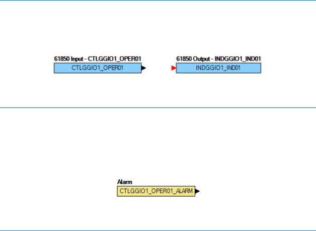
CTLGGIO OPER Output and INDGGIO OPER Input
The IEC 61850 GGIO IND outputs and OPER inputs in BESTCOMSPlus are used to map BE1-11 inputs and outputs to IEC 61850 data points. These data points can be read directly with an IEC 61850 browser such as IED Scout made by Omicron. The GGIO inputs and outputs can be used in an IEC 61850 DataSet which is tied to GOOSE Control Blocks (GoCB) for sending/receiving GOOSE messages.
A CTLGGIO 61850 logic output and INDGGIO logic input are shown in Figure 14.
Figure 14. 61850 Logic Output and Input
CTLGGIO OPER Alarm
The CTLGGIO OPER ALARM is set if the device has subscribed to a GOOSE message, mapped it to the corresponding CTL GGIO, and the device has not received the subscribed GOOSE message within the TTL (Time To Live). The TTL for the next reception is included within a GOOSE message. If the TTL timer expire and the alarm is set, the CTLGGIO OPER logic input will switch over to the default that is configured within the BE1-11 settings. If the device starts receiving GOOSE messages again, the alarm will be reset and the CTLGGIO OPER logic input will be set to the value in the GOOSE message.
A CTLGGIO 61850 logic output and INDGGIO logic input are shown in Figure 14.
Figure 15. CTLGGIO Alarm
IEC61850PTRC Logic Block
The IEC61850PTRC logic block is available to set the corresponding status outputs in the IEC61850 PTRC node. The trip output for the BE1-11 should be connected to the Operate-General input of the block. If trip statuses of individual phases are known, use BESTlogic™Plus to connect them to the Phase A, Phase B, and Phase C logic inputs.
The IEC 61850 PTRC logic block is shown in Figure 16.
BE1-11 |
BESTCOMSPlus® |

18 |
9424200892 Rev F |
Figure 16. IEC61850PTRC Logic Block
BESTCOMSPlus® |
BE1-11 |

9424200892 Rev F |
19 |
BEST61850™
BEST61850 is a Windows®-based, PC application that provides a user-friendly, graphical user interface (GUI) for use with Basler Electric communicating products. The name BEST61850 is an acronym that stands for Basler Electric Software Tool for IEC 61850.
BEST61850 provides the user with a point-and-click means to configure IEC 61850 settings for the BE1-11. BEST61850 performs the following tasks:
•Reads a SCD file and extracts the CID file
•Downloads/uploads a CID file from/to the BE1-11
•Opens a CID file from a PC or network location
•Configures IED network settings
•Configures datasets for report control blocks (RCB) and GOOSE control blocks (GoCB)
•Creates and configures Report Control Blocks (RCB)
•Maps GOOSE messages between IED subscribers
•Creates and configures GoCB for each GOOSE message
•Exports a CID file to a PC or network location
Installation
BEST61850 software is built on the Microsoft® .NET Framework. The setup utility that installs BEST61850 on your PC also installs the required version of .NET Framework (if not already installed). BEST61850 operates with systems using Windows® XP 32-bit SP3, Windows Vista 32-bit SP1 (all editions), Windows 7 32-bit (all editions), Windows 7 64-bit (all editions), and Windows 8. System recommendations for the .NET Framework and BEST61850 are listed in Table 2.
Table 2. System Recommendations for BEST61850 and the .NET Framework
System Type |
Component |
Recommendation |
|
|
|
32-/64-bit |
Processor |
2.0 GHz |
|
|
|
32-/64-bit |
RAM |
1 GB (minimum), 2 GB (recommended) |
|
|
|
32-bit |
Hard Drive |
30 MB (if .NET Framework is already installed on PC) |
|
|
|
|
|
880 MB (if .NET Framework is not already installed on PC) |
|
|
|
64-bit |
Hard Drive |
30 MB (if .NET Framework is already installed on PC) |
|
|
|
|
|
2.1 GB (if .NET Framework is not already installed on PC) |
|
|
|
To install BEST61850, a Windows user must have Administrator rights.
Install BEST61850™
NOTE
Do not connect a USB cable until setup completes successfully. Connecting a USB cable before setup is complete may result in unwanted or unexpected errors.
BE1-11 |
BEST61850™ |

20 |
9424200892 Rev F |
1.Insert the BEST61850 CD-ROM into the PC CD-ROM drive.
2.When the BEST61850 Setup and Documentation CD menu appears, click the Install button for the BEST61850 application. The setup utility installs BEST61850, the .NET Framework (if not already installed), and the USB driver on your PC.
When BEST61850 installation is complete, a Basler Electric folder is added to the Windows programs menu. This folder is accessed by clicking the Windows Start button and then accessing the Basler Electric folder in the Programs menu. The Basler Electric folder contains an icon that starts BEST61850 when clicked.
Menu Bar
The menu bar located near the top of the BEST61850 screen (see Figure 17) has four pull-down menus. The menu bar is described in Table 3.
|
Table 3. Menu Bar (BEST61850) |
|
Menu Item |
|
Description |
|
|
|
File |
|
|
New Workspace |
|
Creates a new workspace |
|
|
|
Open Workspace |
|
Opens a saved workspace |
|
|
|
Save Workspace |
|
Saves the workspace |
|
|
|
Save Workspace As |
|
Saves the workspace with a different file name |
|
|
|
Open SCL File |
|
Opens a CID, ICD, or SCD file |
|
|
|
Exit |
|
Closes BEST61850 software |
|
|
|
View |
|
|
Workspace |
|
Opens the Workspace window |
|
|
|
Status |
|
Opens the Status window |
|
|
|
Default Layout |
|
Opens both the Workspace and the Status windows |
|
|
|
Communication |
|
|
Download CID From Device |
|
Downloads a CID file from the device |
|
|
|
Help |
|
|
Check for Updates |
|
Check for BEST61850 updates via the internet |
|
|
|
Check for Update Settings |
|
Enable or change automatic checking for updates |
|
|
|
About |
|
View general, detailed build, and system information |
|
|
|
BEST61850™ Settings
Device Info
The Device Info tab is illustrated in Figure 17.
BEST61850™ |
BE1-11 |

9424200892 Rev F |
21 |
Figure 17. Device Info Tab
Device Info Settings
The Device Info settings are described in Table 4.
|
|
Table 4. Device Info Settings |
|
Setting |
Range |
|
Description |
|
|
|
|
IED Name |
String (32) |
|
Name of IED (only alphanumeric and underscore characters) |
|
|
|
|
Manufacturer |
n/a |
|
Manufacturer of the IED (read only) |
|
|
|
|
Type |
n/a |
|
Type of IED (read only) |
|
|
|
|
Description |
String (255) |
|
Description of IED (not sent to IED, only saved in BEST61850) |
|
|
|
|
Model Number |
n/a |
|
BE1-11 Style Number |
|
|
|
|
Application Version |
n/a |
|
BE1-11 firmware application verison |
|
|
|
|
IP Address |
Dotted Decimal |
|
IP Address of IED |
|
|
|
|
Subnet Mask |
Dotted Decimal |
|
Subnet Mask of IED |
|
|
|
|
Default Gateway |
Dotted Decimal |
|
Default Gateway of IED |
|
|
|
|
Revision |
n/a |
|
Configuration revision |
|
|
|
|
Datasets
The Datasets tab is illustrated in Figure 18.
BE1-11 |
BEST61850™ |

22 |
9424200892 Rev F |
Figure 18. Datasets Tab
Functional Constraints
The IEC 61850 standard defines a number of functional constraints that indicate the data attribute is used for some particular purpose, such as reporting (BR/RP), configuration (CF), control (CO), description (DC), extended definition (EX), GOOSE control (GO), logging (LG), measured analog value (MX), setting groups (SG), setpoint (SP), and status (ST). The functional constraints of a DATA instance determines the rights of services to read and/or write the DATA.
DATA OBJECT
The DATA OBJECT or DATA class (abbreviated DO) like the LN class, is a key element of the IEC 61850 standard. Values of DATA instances represent meaningful information about substation devices, such as currents, voltages, power, phases, temperatures, status, timestamps, and so on. The DATA OBJECT may contain attributes which are themselves instances of the DATA class. Hence, it can be said that the DATA class is recursively defined.
DATA ATTRIBUTE
The DATA ATTRIBUTE class (abbreviated DA) contains the smallest piece of data that can be defined in IEC 61850. The DA class includes definition of instance name, reference, type, and presence. Presence indicates whether or not the data is mandatory or optional.
Datasets Settings
The Datasets settings are described in Table 5.
BEST61850™ |
BE1-11 |
9424200892 Rev F |
23 |
|||
|
|
Table 5. Datasets Settings |
||
|
Setting |
|
Range |
|
|
|
|
|
|
|
LDevice Inst |
|
List selectable |
|
|
|
|
|
|
|
Logical Node |
|
List selectable |
|
|
|
|
|
|
|
FC |
|
List selectable |
|
|
|
|
|
|
|
DO Name |
|
List selectable |
|
|
|
|
|
|
|
DA Name |
|
List selectable |
|
|
|
|
|
|
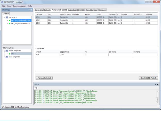
Published IED GOOSE
The Published IED GOOSE tab is illustrated in Figure 19.
Figure 19. Published IED GOOSE Tab
Published IED GOOSE Settings
The Published IED GOOSE settings are described in Table 6.
Table 6. Published IED GOOSE Settings
|
Setting |
Range |
|
|
|
|
|
|
GOOSE Control Name |
String (65) |
|
|
|
|
|
|
Dataset |
String (255) |
|
|
|
|
|
|
Configuration Revision |
1 to 65535 |
|
|
|
|
|
|
APPID |
00 to FF |
|
|
|
|
|
|
|
|
|
BE1-11 |
BEST61850™ |
24 |
|
|
9424200892 Rev F |
|
|
|
|
|
Setting |
Range |
|
|
|
|
|
|
GoID |
String (65) |
|
|
|
|
|
|
MAC Address |
00 to FF (per each hexadecimal group) |
|
|
|
|
|
|
VLAN ID |
000 to FFF |
|
|
|
|
|
|
VLAN Priority |
0 to 7 |
|
|
|
|
|
|
Max Time |
1 to 65536 |
|
|
|
|
|
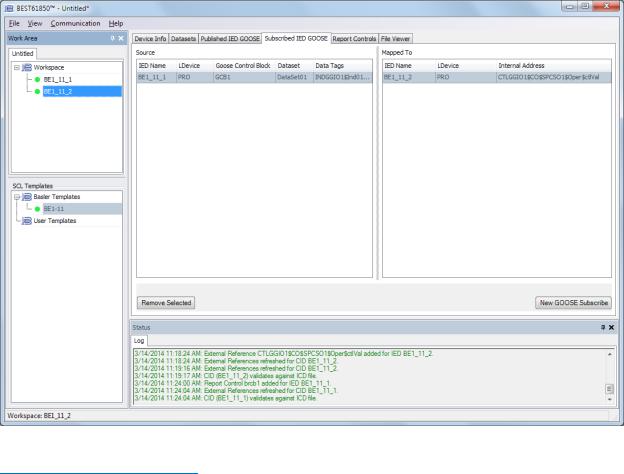
Subscribed IED GOOSE
The Subscribed IED GOOSE tab is illustrated in Figure 20.
Figure 20. Subscribed IED GOOSE Tab
Subscribed IED GOOSE Settings
The Subscribed IED GOOSE settings are described in Table 7.
Table 7. Subscribed IED GOOSE Settings
|
Setting |
Range |
|
|
|
|
|
|
Source |
|
|
|
|
|
|
|
IED Name |
List selectable |
|
|
|
|
|
|
LDevice Inst |
List selectable |
|
|
|
|
|
|
GOOSE Block |
List selectable |
|
|
|
|
|
|
|
|
|
BEST61850™ |
|
BE1-11 |
|
Loading...