


 Loading...
INSTRUCTION MANUAL
FOR
TRANSFORMER DIFFERENTIAL RELAY
BE1-87T
BE1-87T |
|
TRANSFORMER DIFFERENTIAL |
|
Style No. D2E A1J D1S0F |
|
Serial No. XXXXXXXXXXXX |
|
PUSH TO |
|
ENERGIZE |
|
OUTPUT |
|
R |
U |
P0052-22 |
|
Publication: |
9171300990 |
|
Revision: |
V |
03/12 |

INTRODUCTION
This instruction manual provides information about the operation and installation of the BE1-87T Transformer Differential relay. To accomplish this, the following information is provided:
General Information and Specifications
Controls and Indicators
Functional Description
Installation
Test Procedures
WARNING!
To avoid personal injury or equipment damage, only qualified personnel should perform the procedures in this manual.
NOTE
Be sure that the BE1-87T is hard-wired to earth ground with no smaller than 12 AWG copper wire attached to the ground terminal on the rear of the unit case. When the BE1-87T is configured in a system with other devices, it is recommended to use a separate lead to the ground bus from each unit.
9171300990 Rev V |
BE1-87T Introduction |
i |

First Printing: June 1990
Printed in USA
Copyright © 1990-2012 Basler Electric, Highland Illinois 62249 USA
All Rights Reserved
March 2012
CONFIDENTIAL INFORMATION
of Basler Electric, Highland Illinois, USA. It is loaned for confidential use, subject to return on request, and with the mutual understanding that it will not be used in any manner detrimental to the interest of Basler Electric.
It is not the intention of this manual to cover all details and variations in equipment, nor does this manual provide data for every possible contingency regarding installation or operation. The availability and design of all features and options are subject to modification without notice. Should further information be required, contact Basler Electric.
For terms of service relating to this product and software, see the Commercial Terms of Products and Services document available at www.basler.com/terms.
BASLER ELECTRIC
12570 STATE ROUTE 143
HIGHLAND IL 62249-1074 USA http://www.basler.com, info@basler.com
PHONE +1 618.654.2341 |
FAX +1 618.654.2351 |
ii |
BE1-87T Introduction |
9171300990 Rev V |

REVISION HISTORY
The following information provides a historical summary of the changes made to the BE1-87T instruction manual (9171300990). Revisions are listed in reverse chronological order.
Manual |
Change |
|
Revision and Date |
||
|
||
V, 03/12 |
Updated format of Table 1-3, Power Supply Ratings, to be consistent |
|
|
with other manuals. |
|
|
Standardized case and cover drawings in Section 4. |
|
|
|
|
U, 08/11 |
Updated 2nd harmonic restraint specs for 5 A & 1 A CTs in Section 5. |
|
|
Updated formatting to current style used. |
|
|
|
|
T, 03/11 |
Updated 2nd & 5th harmonic restraint specs in Section 1. |
|
|
|
|
S, 09/10 |
Updated “K” type power supply burden in Table 1-3. |
|
|
Updated GOST-R statement in Section 1. |
|
|
Updated rear case drawings in Section 4. |
|
|
Removed references to extender card in Sections 4 and 5. |
|
|
Updated Storage statement in Section 4. |
|
|
|
|
R, 09/07 |
Replaced magnetic type targets with electronic type targets. |
|
|
Updated power supply burden data and output contact ratings. |
|
|
Updated front panel illustrations to show laser graphics. |
|
|
Moved content of Section 6, Maintenance to Section 4, Installation. |
|
|
Added GOST-R certification to Section 1, General Information. |
|
|
|
|
Q, 10/05 |
In Section 1, General Information, Specifications, corrected values for |
|
|
Maximum Current per Input for 1 Ampere CT Units. |
|
|
In Section 5, Test Procedures, corrected values inside CAUTION box |
|
|
for 1 AMP CT on page 5-14. |
|
|
|
|
P, 05/03 |
Added a thumbscrew to the figure on the manual front cover. |
|
|
Added “not all styles” to the Power Supply Output heading on page 3- |
|
|
4 as well as added “NOTE” and a text box around the second last |
|
|
paragraph on page 3-4. |
|
|
Added the new thumbscrew to Figure 4-1 and changed the height |
|
|
dimensions in Figure 4-2. |
|
|
Clarified the terminal numbers on Figure 4-6b. |
|
|
Added a shorting bar between terminals 6 & 7 in Figure 4-11. |
|
|
Added a shorting bar and normally open contact and normally closed |
|
|
contact effecting terminals 1, 2, & 5 in Figure 4-12. |
|
|
Step 13 was corrected on pages 4-31 and 4-39 to include Rw in the |
|
|
formulas. |
|
|
Values were changed to Table 5-4 under Option 1-0 for Unrestrained |
|
|
Trip. |
|
|
|
|
N, 09/00 |
Corrected Table 1-3 to show power supply ranges. |
|
|
Changed instruction manual front cover, Figures 4-1, 4-3, and 4-5 to |
|
|
show new unit case covers. |
|
|
Changed Figure 4-32 per markup. |
|
|
|
9171300990 Rev V |
BE1-87T Introduction |
iii |

Manual |
|
Change |
|
Revision and Date |
|
|
|
|
|
|
|
M, 04/99 |
|
Table 3-1 changed mid range nominal volt 125 Vac to 120 Vac. |
|
|
Corrected Figures 4-24, 4-31a, and A-3 |
||
|
Corrected page 4-38, Step 10; added note to page 4-39, Step 13, and |
||
|
|
corrected Steps 14 and 16. |
|
|
Page A-2, changed 3-Phase fault ratio current to 3-phase fault |
||
|
|
current. |
|
|
Page A-3, corrected formulas for Figure A-3. |
||
|
Under Section 4, Procedure One, Verify CT Performance, changed |
||
|
|
the procedure to the ANSI accuracy class method. This forced |
|
|
|
changes in the following steps: 12, 13, 14, 16, 18, 20, and 21. |
|
|
Under Section 4, Procedure Two, Verify CT Performance, changed |
||
|
|
the procedure to the ANSI accuracy class method. This forced |
|
|
|
changes in the following steps: 12, 13, 14, and 16. |
|
|
Added ECO revision information to Table 8-1. |
||
|
Added Setting Note 7 (ANSI Accuracy Class Method) to Appendix A. |
||
|
|
|
|
L, 05/97 |
|
To delete the part number from the front cover of the manual. |
|
|
|
|
|
K, 03/97 |
|
Deleted all references to Service Manual 9171300620. |
|
|
Changed the Title of Section 2 from “Controls and Indicators” to |
||
|
|
“Human-Machine Interface”. |
|
|
Replaced the Power Supply Options paragraphs with a new Power |
||
|
|
Supply paragraph explaining the new power supply design. |
|
|
Deleted Figure 3-2 and added Table 3-1, Wide Range Power Supply |
||
|
|
Voltage Ranges. |
|
|
Changed Power Supply Status Output for Type G power supply on |
||
|
|
the formerly page 3-6 (now page 3-4) from terminals 9 and 20 to |
|
|
|
terminals 9 and 19. |
|
|
Added information to Section 4 to help the user understand the |
||
|
|
procedures better. |
|
|
Deleted all NOTES FOR USERS OF SENSING INPUT TYPE F |
||
|
|
RELAYS and added Section 7, Difference Data. |
|
|
Changed previous Section 7, Manual Change Information, to Section |
||
|
|
8. |
|
|
Added an Appendix A to clarify the setting procedures. |
||
|
Added an index to help the user find information easier. |
||
|
Changed the format of the manual. |
||
|
|
|
|
J, 01/96 |
|
Deleted “Difference Data” (formerly Section 7) and included notes for |
|
|
|
users of Type F relays. |
|
|
Moved all information regarding relay settings and checking relay |
||
|
|
setting from Section 5, Testing and Setting, to Section 4, Installation. |
|
|
|
Section 5 now contains information on test procedures. |
|
|
Combined 50 and 60 Hz Verification Tests. |
||
|
|
Various editorial changes. |
|
|
Reformatted instruction manual as Windows Help file for electronic |
||
|
|
documentation. |
|
|
|
|
|
iv |
BE1-87T Introduction |
9171300990 Rev V |

Manual |
|
Change |
Revision and Date |
|
|
|
|
|
I, 01/95 |
|
Added outline (box) to Figure 5-8 to highlight the figure. |
|
Page 5-42, Step 5, changed, “should be less than 4.45” to, “must be |
|
|
|
less than 4.45”. |
|
Added note to page 5-43, Step 10 and corrected the formula in Step |
|
|
|
10. |
|
Page 5-45, Step 18, corrected formula and high side results; and |
|
|
|
Step 19, changed last sentence from H (13 x tap) to S (21 x tap). |
|
Page 5-46, Steps 20 and 21, corrected figure references. |
|
|
|
|
H, 12/94 |
|
Page 1-6, changed Specification for Restrained Output, Pickup |
|
|
Accuracy. |
|
Changed Section 5, Testing and Setting, Verification Tests (all |
|
|
|
models): Steps 1, 4, 5, and 8; and Table 5-4. |
|
Page 5-50, Jumper Positions Wye-Delta 1, Step 3: Corrected Input 2 |
|
|
|
terminal identifications. |
|
Page 5-51, Jumper Positions Delta2-Delta2, Step 2: Corrected |
|
|
|
verification statement. |
|
|
|
G, 09/94 |
|
Changed all sections to reflect new Option 1-1. |
|
Added to Section 5 four examples for testing relays to clarify test |
|
|
|
procedures. |
|
Added to Section 5 one procedure for setting relays. |
|
|
Corrected typographical and illustration errors. |
|
|
|
|
F, 03/93 |
|
Changed formula pages 5-4, 5-10, 5-16, and 5-22 from I = the square |
|
|
root of K over t, to I = K over the square root of t. |
|
|
|
E, 01/93 |
|
Manual was revised to incorporate a revision in the relay that made |
|
|
sensing input type F obsolete and included the 1 A, 60 hertz and 5 A, |
|
|
50 hertz model relays. |
|
Section 5, Test Setup, diagrams were changed to clarify relay |
|
|
|
connections. |
|
Added three relay Internal Connection diagrams. |
|
|
Changed unrestrained maximum time to trip, reference old Tables 5-4 |
|
|
|
and 5-8 (new Tables 5-4, 5-8, 5-12, and 5-16). |
|
Renamed Section 7, Manual Change Information to Section 8, |
|
|
|
Manual Change Information and added new Section 7, Difference |
|
|
Data to support BE1-87T relays with Sensing Input Type F. |
|
|
|
D, 06/92 |
|
Manual was revised to include the 1 A, 50 Hz model relay and |
|
|
reformatted to a new Instruction Manual style. |
|
Additional connection diagrams were included in Section 4 and test |
|
|
|
plug information was added to Section 6. |
|
Minor typographical errors were also corrected. |
|
|
|
|
C, 03/91 |
|
Table 5-1 was expanded and Figure 5-4 Test Setup illustration was |
|
|
added. |
|
|
Miscellaneous editing. |
|
|
|
B, 03/91 |
|
Manual (with the exception of Section 2) was rewritten for ease of |
|
|
use. |
|
|
|
A, 06/90 |
|
Figure 3-1 (Functional Block Diagram) corrected. |
|
Formula in caution note (formerly on p. 4-17, now on p. 5-2) |
|
|
|
corrected. |
|
|
Miscellaneous editing. |
|
|
|
9171300990 Rev V |
BE1-87T Introduction |
v |

|
|
|
|
|
|
|
|
vi |
|
BE1-87T Introduction |
9171300990 Rev V |

CONTENTS
SECTION 1 • GENERAL INFORMATION ................................................................................................ |
1-1 |
|
SECTION 2 • CONTROLS AND INDICATORS........................................................................................ |
2-1 |
|
SECTION 3 |
• FUNCTIONAL DESCRIPTION ........................................................................................... |
3-1 |
SECTION 4 |
• INSTALLATION .................................................................................................................. |
4-1 |
SECTION 5 |
• TEST PROCEDURES ........................................................................................................ |
5-1 |
SECTION 6 |
• DIFFERENCE DATA .......................................................................................................... |
6-1 |
APPENDIX A • SETTING NOTES ............................................................................................................ |
A-1 |
|
9171300990 Rev V |
BE1-87T Introduction |
vii |

|
|
|
|
|
|
|
|
viii |
|
BE1-87T Introduction |
9171300990 Rev V |
SECTION 1 • GENERAL INFORMATION
TABLE OF CONTENTS
SECTION 1 • GENERAL INFORMATION ................................................................................................ |
1-1 |
Introduction ............................................................................................................................................ |
1-1 |
Description ............................................................................................................................................. |
1-1 |
Application.............................................................................................................................................. |
1-2 |
Single-Phase ...................................................................................................................................... |
1-2 |
Three-Phase....................................................................................................................................... |
1-2 |
Percentage Restraint.......................................................................................................................... |
1-2 |
Second-Harmonic Restraint ............................................................................................................... |
1-2 |
Fifth-Harmonic Restraint .................................................................................................................... |
1-3 |
Unrestrained Trip................................................................................................................................ |
1-3 |
Options................................................................................................................................................... |
1-3 |
Push-To-Energize Output Pushbuttons ............................................................................................. |
1-3 |
Auxiliary Output Contacts................................................................................................................... |
1-3 |
Power Supply ..................................................................................................................................... |
1-3 |
Model and Style Number ....................................................................................................................... |
1-4 |
Style Number Example....................................................................................................................... |
1-4 |
Specifications ......................................................................................................................................... |
1-5 |
Figures
Figure 1-1. |
Style Number Identification Chart ........................................................................................... |
1-4 |
Figure 1-2. |
Percentage Restraint Characteristic ....................................................................................... |
1-6 |
Figure 1-3. Unrestrained Response Times and Restrained Response Times.......................................... |
1-8 |
|
Tables
Table 1-1. |
Multiples of Tap ........................................................................................................................ |
1-6 |
Table 1-2. |
Harmonic Attenuation............................................................................................................... |
1-7 |
Table 1-3. |
Power Supply Specifications.................................................................................................... |
1-9 |
9171300990 Rev V |
BE1-87T General Information |
i |

|
|
|
|
|
|
|
|
ii |
|
BE1-87T General Information |
9171300990 Rev V |

SECTION 1 • GENERAL INFORMATION
Introduction
These instructions provide information concerning the operation and installation of BE1-87T Transformer Differential Relays. To accomplish this, the following is provided:
•Specifications
•Functional characteristics
•Mounting information
•Setting procedures and examples
WARNING!
To avoid personal injury or equipment damage, only qualified personnel should perform the procedures presented in these instructions.
These instructions may be used in place of all earlier editions. For change information, see Section 8.
Description
BE1-87T Transformer Differential Relays provide primary protection for power transformers and are available in either Single-Phase or Three-Phase configurations. The solid-state BE1-87T compares the currents entering and leaving the protected transformer. If a fault is detected, the relay initiates a trip signal to isolate the power transformer. This limits damage to the transformer and minimizes the impact on the power system.
BE1-87T relays use three types of restraint:
NOTE FOR USERS OF SENSING INPUT TYPE F RELAYS
Users of BE1-87T relays with Sensing Input Type F (three-phases three inputs per phase) will find Difference Data in Section 6 of this manual that describes features specific to these relays. The three-phase, three inputs per phase design, previously available as Sensing Input Type F, has been modified and is now available as Sensing Input Type G. Due to differences in components and output terminal connections, Type G relays are not compatible with earlier versions of the BE1-87T with Sensing Input Type F. There are also differences in the output connections as described in Section 6, Difference Data.
•Percentage of through-current
•Second harmonic
•Fifth harmonic
Selectivity in differential relaying is based on the ability to distinguish between internal and external faults. This is achieved by comparing the currents into and out of a power transformer. Comparing these currents often requires more than two inputs. For example:
•Power transformers may have a significant portion (greater than 10%) of the current flowing in a third or tertiary winding.
•Power transformers can have multiple breakers for a given winding (e.g., ring bus or breaker-and- a-half bus).
BE1-87T relays are available with up to five restraint inputs for the single-phase unit and up to three restraint inputs per phase for the three-phase unit.
9171300990 Rev V |
BE1-87T General Information |
1-1 |

Application
In general, power transformers have different values of current flowing through their primary, secondary, and tertiary windings. These currents have specific phase relationships depending upon the connections of the individual windings (e.g., wye/delta). As inputs to a differential relay, these currents must be compensated or scaled so that the relay can compare the inputs and determine when an unbalance exists. Under ideal operating conditions, the scaled vector sum of these currents is zero.
Because it is practically impossible to match the magnitudes of these detected currents from the various power windings using standard CT ratios, the currents are matched within the relay by scaling each of the applied currents by an appropriate factor called a Tap Setting. This is set by means of the front panel INPUT dials. By selecting suitable tap ratios, the applied currents are scaled within the relay to achieve the desired balance for normal operating conditions. BE1-87T relays offer a range of available tap settings for inputs between 0.4 A to 1.78 A (Sensing Input Range Options 2 and 4 for a 1 A CT) or 2.0 to 8.9 A (Sensing Input Range Options 1 and 3 for a 5 A CT). These settings are independently adjustable in increments of 0.02 A for Sensing Input Range Options 2 and 4, or 0.1 A for Sensing Input Range Options 1 and 3. These small increments allow more precise scaling of the applied currents and usually eliminate the need for installing auxiliary ratio-matching CTs.
Single-Phase
BE1-87T Single-Phase relays require phase angle compensation to be accomplished externally by proper connection of the system CT secondaries. A wye/delta transformer requires that the CT secondaries be connected in delta for the wye winding and in wye for the delta winding. This type of connection also eliminates the zero-sequence component of current which could cause a false trip (operation) during external ground fault conditions on the wye system.
Three-Phase
BE1-87T Three-Phase relays can provide zero-sequence filtering and compensation for phase shifts introduced by the connections of the power transformer. This 30° Phase Shift compensation (either ±30° or no compensation) is field selectable. Additionally, this feature allows sharing the transformer differential relay CTs with other relays or instrumentation.
BE1-87T relays use the highest input current (in per unit values) to operate on maximum restraint. The relay does not have a conventional operate winding in the internal magnetics. Operating current is developed within the electronics of the relay.
Percentage Restraint
A primary concern in differential relay applications is security against high current levels caused by faults outside the protected zone. Inevitable differences in the saturation characteristics between current transformers require a compensating decrease in relay sensitivity. It is also necessary to be able to adjust the sensitivity to compensate for transformer voltage taps or CT mismatches. This is accomplished by providing a restraint factor proportional to the current flowing through the protected zone (throughcurrent).
BE1-87T relays maintain sensitivity at a specified ratio of trip current to through current. This ratio, generally referred to as slope, is front-panel adjustable in 5% increments from 15 to 60%.
Second-Harmonic Restraint
Magnetizing inrush current presents another problem unique to transformer differential relays. Relays must be capable of detecting the small differences in current caused by the shorting of a limited number of turns, yet remain secure against the occurrence of magnetizing currents many times the transformer rating (as seen at one set of terminals).
Although magnetizing inrush is usually associated with the energizing of the transformer, any abrupt change in the energizing voltage may produce this phenomenon. Common causes are the transients generated during the onset, evolution, and removal of external faults. Desensitizing the relay only during energization is therefore insufficient.
Magnetizing inrush produces an offset sine wave rich in all harmonics. BE1-87T relays use the second harmonic to restrain operation because it predominates and because it does not occur in significant magnitude or duration at other times.
1-2 |
BE1-87T General Information |
9171300990 Rev V |

Three-phase BE1-87T relays use second-harmonic sharing. The second-harmonic content of all three phases is summed together to derive the restraint for each phase. As a result, the second-harmonic inhibit range and the associated factory setting, is higher than on single-phase relays.
Fifth-Harmonic Restraint
Power transformer overexcitation causes additional exciting current to flow into one set of terminals. This presents an apparent differential (or operating) current not attributable to an internal fault. Although potentially damaging, overexcitation is not an internal fault and, therefore, is not an appropriate condition for transformer differential relay operation. One of the principal components in the complex waveform produced during overexcitation is the fifth harmonic. BE1-87T relays use fifth-harmonic restraint to inhibit the differential relay operation.
Unrestrained Trip
Severe internal transformer faults may cause CT saturation. Under such circumstances, harmonicrestraint transformer differential relays may fail to trip because of the extremely high harmonic content in the waveform. Lack of operation can result in severe transformer damage.
BE1-87T relays provide an independent unrestrained tripping function. When set above the possible inrush current magnitude, this function provides high-speed protection for the most severe internal faults.
Options
Push-To-Energize Output Pushbuttons
Two PUSH-TO-ENERGIZE OUTPUT switches are available as a means to verify external output wiring without the inconvenience of having to test the entire relay. Option 2-S provides a small pushbutton switch for each isolated output function (Restrained and Unrestrained) and may be actuated by inserting a thin, non-conducting rod through access holes in the front panel. Refer to Figures 2-1 through 2-4 for location.
Appropriate power must be applied to Power Supply terminals 3 and 4 (shown in Figures 4-7 through 4- 10) for these pushbuttons to operate the output relays. However, it is not necessary to apply currents to the sensing inputs of the relay for these switches to function.
Auxiliary Output Contacts
Three types of auxiliary output contacts are available: Normally open, normally closed and SPDT. The contacts can be made to respond to a restrained trip, an unrestrained trip, or both. Refer to the Functional Description: Auxiliary Relay Option for further information.
Power Supply
Various power supply options are available to allow the BE1-87T to be used with standard supply voltages. See the Style Number Identification Chart, Figure 1-1, for details.
9171300990 Rev V |
BE1-87T General Information |
1-3 |
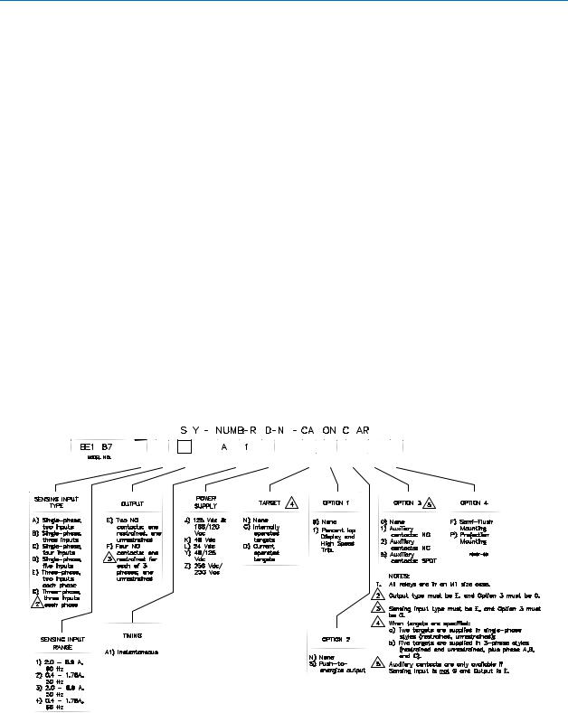
Model and Style Number
The electrical characteristics and operational features of the BE1-87T Transformer Differential Relay are defined by a combination of letters and numbers that make up its Style Number. The Model Number together with the Style Number, describe the options included in a specific device and appear on the front panel, drawout cradle and inside the case assembly.
Upon receipt of a relay, be sure to check the Style Number against the requisition and the packing list to ensure that they agree.
Style Number Example
The Style Number Identification Chart (Figure 1-1) defines the electrical characteristics and operational features included in BE1-87T relays. For example, if the Style Number were G1E-A1Y-D1S0F, the device would have the following:
BE1-87T Model Number (designates the relay as a Basler Electric, Class 100, Transformer Differential
|
Relay) |
|||||||||||||||||||||||||||||||||||||||||||||||||||||||||||||||||||
G |
Three-phase sensing with three inputs per phase |
|||||||||||||||||||||||||||||||||||||||||||||||||||||||||||||||||||
1 |
2.0 to 8.9 A Sensing Range at 60 Hz |
|||||||||||||||||||||||||||||||||||||||||||||||||||||||||||||||||||
E |
One unrestrained output contact and one restrained output contact |
|||||||||||||||||||||||||||||||||||||||||||||||||||||||||||||||||||
A1 |
No intentional delay in the outputs |
|||||||||||||||||||||||||||||||||||||||||||||||||||||||||||||||||||
Y |
48/125 Vdc switchable |
|||||||||||||||||||||||||||||||||||||||||||||||||||||||||||||||||||
D |
Current operated targets |
|||||||||||||||||||||||||||||||||||||||||||||||||||||||||||||||||||
1 |
Percent IOP display and high-speed trip |
|||||||||||||||||||||||||||||||||||||||||||||||||||||||||||||||||||
S |
Push-to-Energize outputs |
|||||||||||||||||||||||||||||||||||||||||||||||||||||||||||||||||||
0 |
No auxiliary output |
|||||||||||||||||||||||||||||||||||||||||||||||||||||||||||||||||||
F |
Semi-flush mounting |
|||||||||||||||||||||||||||||||||||||||||||||||||||||||||||||||||||
|
|
|
|
|
|
|
|
|
|
|
|
|
|
|
|
|
|
|
|
|
|
|
|
|
|
|
|
|
|
|
|
|
|
|
|
|
|
|
|
|
|
|
|
|
|
|
|
|
|
|
|
|
|
|
|
|
|
|
|
|
|
|
|
|
|
|
|
|
|
|
|
|
|
|
|
|
|
|
|
|
|
|
|
|
|
|
|
|
|
|
|
|
|
|
|
|
|
|
|
|
|
|
|
|
|
|
|
|
|
|
|
|
|
|
|
|
|
|
|
|
|
|
|
|
|
|
|
|
|
|
|
|
|
|
|
|
|
|
|
|
|
|
|
|
|
|
|
|
|
|
|
|
|
|
|
|
|
|
|
|
|
|
|
|
|
|
|
|
|
|
|
|
|
|
|
|
|
|
|
|
|
|
|
|
|
|
|
|
|
|
|
|
|
|
|
|
|
|
|
|
|
|
|
|
|
|
|
|
|
|
|
|
|
|
|
|
|
|
|
|
|
|
|
|
|
|
|
|
|
|
|
|
|
|
|
|
|
|
|
|
|
|
|
|
|
|
|
|
|
|
|
|
|
|
|
|
|
|
|
|
|
|
|
|
|
|
|
|
|
|
|
|
|
|
|
Figure 1-1. Style Number Identification Chart
1-4 |
BE1-87T General Information |
9171300990 Rev V |

Specifications
The BE1-87T relay is available in either single-phase or three-phase configurations and with the following features and capabilities.
Current Sensing Inputs |
The unit is designed to operate from the secondary of current |
|||||||
|
|
transformers rated at either 1 A or 5 A. Frequency range is ±5 Hz of |
||||||
|
|
nominal. |
|
|
|
|||
Maximum Current Per Input |
|
|
|
|
|
|
|
|
|
1 Ampere CT Units |
4 A continuous; 50 A or 50 X tap (whichever is less) for 1 second. |
||||||
|
5 Ampere CT Units |
20 A continuous; 250 A or 50 X tap (whichever is less) for 1 |
||||||
|
|
second. |
|
|
|
|||
|
|
For ratings other than one second, the rating may be calculated as: |
||||||
|
|
I = |
K |
|
|
|
|
|
|
|
|
|
|
|
|
|
|
|
|
t |
|
|
|
|||
|
|
|
|
|
|
|
||
|
|
Where: |
|
|
|
|||
|
|
|
t is the time (in seconds) that the current flows |
|||||
|
|
|
K = 50 A or 50 X tap, whichever is less (1 Amp CT Units), or |
|||||
|
|
|
K = 250 A or 50 X tap, whichever is less (5 Amp CT Models) |
|||||
Current Sensing Burden |
Less than 0.02 ohm per phase. |
|||||||
Tap Setting Control (Scaling) |
Front panel rotary switches, labeled INPUT, permit scaling the |
|||||||
|
|
sensed input current (or tap setting) over the range of: |
||||||
1 |
Ampere CT Units |
0.4 to 1.78 in 0.02 A increments. |
||||||
5 |
Ampere CT Units |
2.0 to 8.9 A, in 0.1 A increments. |
||||||
Restrained Output |
|
|
|
|
|
|
|
|
Pickup Range |
Front panel thumbwheel switches adjust pickup of the restrained |
|||||||
|
|
output as a percentage of the through current. The range is 15 to |
||||||
|
|
60% of the operating current in 5% increments. |
||||||
Pickup Accuracy |
±6% of pickup ±100 mA (5 Ampere Units) or ±20 mA (1 Ampere |
|||||||
|
|
units). |
|
|
|
|||
Minimum Pickup |
0.35 ±6% of tap setting. Refer to Table 1-1 and Figure 1-2. Table 1-1 |
|||||||
|
|
provides calculated intersection points of the slope characteristic |
||||||
|
|
and the minimum pickup (in multiples of tap) as shown in Figure |
||||||
|
|
1-2. The calculation was derived from the formula: |
||||||
|
|
|
Maximum IRestraint |
= Minimum Pickup |
||||
|
|
|
|
|
|
|
Percent of Slope |
|
|
|
For example: |
|
|
|
|||
|
|
|
Minimum Pickup = |
|
0.35 |
=1.75 |
||
|
|
|
|
Percent of Slope |
20 % |
|||
The relay operates when the per unit difference current (operating current) is above the 0.35 pu or the slope line in Figure 1-2. Calculation examples are found in Section 5.
9171300990 Rev V |
BE1-87T General Information |
1-5 |
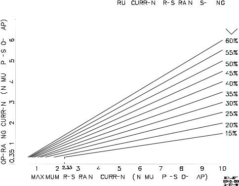
Table 1-1. Multiples of Tap
Front Panel Setting % |
15 |
20 |
|
|
25 |
|
30 |
|
35 |
|
40 |
|
45 |
|
|
|
50 |
|
|
|
|
|
|
55 |
|
|
60 |
|||||||||||||||||||||||||||||||||||||||||||||||||||||||||||||||||||||||||||||
Maximum Restraint |
2.33 |
1.75 |
1.40 |
1.17 |
1.00 |
0.875 |
0.778 |
0.700 |
0.636 |
0.583 |
||||||||||||||||||||||||||||||||||||||||||||||||||||||||||||||||||||||||||||||||||||||||||||||
Current At Minimum |
|
|
|
|
|
|
|
|
|
|
|
|
|
|
|
|
|
|
|
|
|
|
|
|
|
|
|
|
|
|
|
|
|
|
|
|
|
|
|
|
|
|
|
|
|
|
|
|
|
|
|
|
|
|
|
|
|
|
|
|
|
|
|
|
|
|
|
|
|
|
|
|
|
|
|
|
|
|
|
|
|
|
|
|
|
|
|
|
|
|
|
|
|
|
|
|
|
|||||||
Pickup In Multiples of |
|
|
|
|
|
|
|
|
|
|
|
|
|
|
|
|
|
|
|
|
|
|
|
|
|
|
|
|
|
|
|
|
|
|
|
|
|
|
|
|
|
|
|
|
|
|
|
|
|
|
|
|
|
|
|
|
|
|
|
|
|
|
|
|
|
|
|
|
|
|
|
|
|
|
|
|
|
|
|
|
|
|
|
|
|
|
|
|
|
|
|
|
|
|
|
|
|
|||||||
Tap |
|
|
|
|
|
|
|
|
|
|
|
|
|
|
|
|
|
|
|
|
|
|
|
|
|
|
|
|
|
|
|
|
|
|
|
|
|
|
|
|
|
|
|
|
|
|
|
|
|
|
|
|
|
|
|
|
|
|
|
|
|
|
|
|
|
|
|
|
|
|
|
|
|
|
|
|
|
|
|
|
|
|
|
|
|
|
|
|
|
|
|
|
|
|
|
|
|
|||||||
|
|
|
|
|
|
|
|
|
|
|
|
|
|
|
|
|
|
|
|
|
|
|
|
|
|
|
|
|
|
|
|
|
|
|
|
|
|
|
|
|
|
|
|
|
|
|
|
|
|
|
|
|
|
|
|
|
|
|
|
|
|
|
|
|
|
|
|
|
|
|
|
|
|
|
|
|
|
|
|
|
|
|
|
|
|
|
|
|
|
|
|
|
|
|
|
|
|
|
|
|
|
|
|
|
|
|
|
|
|
|
|
|
|
|
|
|
|
|
|
|
|
|
|
|
|
|
|
|
|
|
|
|
|
|
|
|
|
|
|
|
|
|
|
|
|
|
|
|
|
|
|
|
|
|
|
|
|
|
|
|
|
|
|
|
|
|
|
|
|
|
|
|
|
|
|
|
|
|
|
|
|
|
|
|
|
|
|
|
|
|
|
|
|
|
|
|
|
|
|
|
|
|
|
|
|
|
|
|
|
|
|
|
|
|
|
|
|
|
|
|
|
|
|
|
|
|
|
|
|
|
|
|
|
|
|
|
|
|
|
|
|
|
|
|
|
|
|
|
|
|
|
|
|
|
|
|
|
|
|
|
|
|
|
|
|
|
|
|
|
|
|
|
|
|
|
|
|
|
|
|
|
|
|
|
|
|
|
|
|
|
|
|
|
|
|
|
|
|
|
|
|
|
|
|
|
|
|
|
|
|
|
|
|
|
|
|
|
|
|
|
|
|
|
|
|
|
|
|
|
|
|
|
|
|
|
|
|
|
|
|
|
|
|
|
|
|
|
|
|
|
|
|
|
|
|
|
|
|
|
|
|
|
|
|
|
|
|
|
|
|
|
|
|
|
|
|
|
|
|
|
|
|
|
|
|
|
|
|
|
|
|
|
|
|
|
|
|
|
|
|
|
|
|
|
|
|
|
|
|
|
|
|
|
|
|
|
|
|
|
|
|
|
|
|
|
|
|
|
|
|
|
|
|
|
|
|
|
|
|
|
|
|
|
|
|
|
|
|
|
|
|
|
|
|
|
|
|
|
|
|
|
|
|
|
|
|
|
|
|
|
|
|
|
|
|
|
|
|
|
|
|
|
|
|
|
|
|
|
|
|
|
|
|
|
|
|
|
|
|
|
|
|
|
|
|
|
|
|
|
|
|
|
|
|
|
|
|
|
|
|
|
|
|
|
|
|
|
|
|
|
|
|
|
|
|
|
|
|
|
|
|
|
|
|
|
|
|
|
|
|
|
|
|
|
|
|
|
|
|
|
|
|
|
|
|
|
|
|
|
|
|
|
|
|
|
|
|
|
|
|
|
|
|
|
|
|
|
|
|
|
|
|
|
|
|
|
|
|
|
|
|
|
|
|
|
|
|
|
|
|
|
|
|
|
|
|
|
|
|
|
|
|
|
|
|
|
|
|
|
|
|
|
|
|
|
|
|
|
|
|
|
|
|
|
|
|
|
|
|
|
|
|
|
|
|
|
|
|
|
|
|
|
|
|
|
|
|
|
|
|
|
|
|
|
|
|
|
|
|
|
|
|
|
|
|
|
|
|
|
|
|
|
|
|
|
|
|
|
|
|
|
|
|
|
|
|
|
|
|
|
|
|
|
|
|
|
|
|
|
|
|
|
|
|
|
|
|
|
|
|
|
|
|
|
|
|
|
|
|
|
|
|
|
|
|
|
|
|
|
|
|
|
|
|
|
|
|
|
|
|
|
|
|
|
|
|
|
|
|
|
|
|
|
|
|
|
|
|
|
|
|
|
|
|
|
|
|
|
|
|
|
|
|
|
|
|
|
|
|
|
|
|
|
|
|
|
|
|
|
|
|
|
|
|
|
|
|
|
|
|
|
|
|
|
|
|
|
|
|
|
|
|
|
|
|
|
|
|
|
|
|
|
|
|
|
|
|
|
|
|
|
|
|
|
|
|
|
|
|
|
|
|
|
|
|
|
|
|
|
|
|
|
|
|
|
|
|
|
|
|
|
|
|
|
|
|
|
|
|
|
|
|
|
|
|
|
|
|
|
|
|
|
|
|
|
|
|
|
|
|
|
|
|
|
|
|
|
|
|
|
|
|
|
|
|
|
|
|
|
|
|
|
|
|
|
|
|
|
|
|
|
|
|
|
|
|
|
|
|
|
|
|
|
|
|
|
|
|
|
|
|
|
|
|
|
|
|
|
|
|
|
|
|
|
|
|
|
|
|
|
|
|
|
|
|
|
|
|
|
|
|
|
|
|
|
|
|
|
|
|
|
|
|
|
|
|
|
|
|
|
|
|
|
|
|
|
|
|
|
|
|
|
|
|
|
|
|
|
|
|
|
|
|
|
|
|
|
|
|
|
|
|
|
|
|
|
|
|
|
|
|
|
|
|
|
|
|
|
|
|
|
|
|
|
|
|
|
|
|
|
|
|
|
|
|
|
|
|
|
|
|
|
|
|
|
|
|
|
|
|
|
|
|
|
|
|
|
|
|
|
|
|
|
|
|
|
|
|
|
|
|
|
|
|
|
|
|
|
|
|
|
|
|
|
|
|
|
|
|
|
|
|
|
|
|
|
|
|
|
|
|
|
|
|
|
|
|
|
|
|
|
|
|
|
|
|
|
|
|
|
|
|
|
|
|
|
|
|
|
|
|
|
|
|
|
|
|
|
|
|
|
|
|
|
|
|
|
|
|
|
|
|
|
|
|
|
|
|
|
|
|
|
|
|
|
|
|
|
|
|
|
|
|
|
|
|
|
|
|
|
|
|
|
|
|
|
|
|
|
|
|
|
|
|
|
|
|
|
|
|
|
|
|
|
|
|
|
|
|
|
|
|
|
|
|
|
|
|
|
|
|
|
|
|
|
|
|
|
|
|
|
|
|
|
|
|
|
|
|
|
|
|
|
|
|
|
|
|
|
|
|
|
|
|
|
|
|
|
|
|
|
|
|
|
|
|
|
|
|
|
|
|
|
|
|
|
|
|
|
|
|
|
|
|
|
|
|
|
|
|
|
|
|
|
|
|
|
|
|
|
|
|
|
|
|
|
|
|
|
|
|
|
|
|
|
|
|
|
|
|
|
|
|
|
|
|
|
|
|
|
|
|
|
|
|
|
|
|
|
|
|
|
|
|
|
|
|
|
|
|
|
|
|
|
|
|
|
|
|
|
|
|
|
|
|
|
|
|
|
|
|
|
|
|
|
|
|
|
|
|
|
|
|
|
|
|
|
|
|
|
|
|
|
|
|
|
|
|
|
|
|
|
|
|
|
|
|
|
|
|
|
|
|
|
|
|
|
|
|
|
|
|
|
|
|
|
|
|
|
|
|
|
|
|
|
|
|
|
|
|
|
|
|
|
|
|
|
|
|
|
|
|
|
|
|
|
|
|
|
|
|
|
|
|
|
|
|
|
|
|
|
|
|
|
|
|
|
|
|
|
|
|
|
|
|
|
|
|
|
|
|
|
|
|
|
|
|
|
|
|
|
|
|
|
|
|
|
|
|
|
|
|
|
|
|
|
|
|
|
|
|
|
|
|
|
|
|
|
|
|
|
|
|
|
|
|
|
|
|
|
|
|
|
|
|
|
|
|
|
|
|
|
|
|
|
|
|
|
|
|
|
|
|
|
|
|
|
|
|
|
|
|
|
|
|
|
|
|
|
|
|
|
|
|
|
|
|
|
|
|
|
|
|
|
|
|
|
|
|
|
|
|
|
|
|
|
|
|
|
|
|
|
|
|
|
|
|
|
|
|
|
|
|
|
|
|
|
|
|
|
|
|
|
|
|
|
|
|
|
|
|
|
|
|
|
|
|
|
|
|
|
|
|
|
|
|
|
|
|
|
|
|
|
|
|
|
|
|
|
|
|
|
|
|
|
|
|
|
|
|
|
|
|
|
|
|
|
|
|
|
|
|
|
|
|
|
|
|
|
|
|
|
|
|
|
|
|
|
|
|
|
|
|
|
|
|
|
|
|
|
|
|
|
|
|
|
|
|
|
|
|
|
|
|
|
|
|
|
|
|
|
|
|
|
|
|
|
|
|
|
|
|
|
|
|
|
|
|
|
|
|
|
|
|
|
|
|
|
|
|
|
|
|
|
|
|
|
|
|
|
|
|
|
|
|
|
|
|
|
|
|
|
|
|
|
|
|
|
|
|
|
|
|
|
|
|
|
|
|
|
|
|
|
|
|
|
|
|
|
|
|
|
|
|
|
|
|
|
|
|
|
|
|
|
|
|
|
|
|
|
|
|
|
|
|
|
|
|
|
|
|
|
|
|
|
|
|
|
|
|
|
|
|
|
|
|
|
|
|
|
|
|
|
|
|
|
|
|
|
|
|
|
|
|
|
|
|
|
|
|
|
|
|
|
|
|
|
|
|
|
|
|
|
|
|
|
|
|
|
|
|
|
|
|
|
|
|
|
|
|
|
|
|
|
|
|
|
|
|
|
|
|
|
|
|
|
|
|
|
|
|
|
|
|
|
|
|
|
|
|
|
|
|
|
|
|
|
|
|
|
|
|
|
|
|
|
|
|
|
|
|
|
|
|
|
|
|
|
|
|
|
|
|
|
|
|
|
|
|
|
|
|
|
|
|
|
|
|
|
|
|
|
|
|
|
|
|
|
|
|
|
|
|
|
|
|
|
|
|
|
|
|
|
|
|
|
|
|
|
|
|
|
|
|
|
|
|
|
|
|
|
|
|
|
|
|
|
|
|
|
|
|
|
|
|
|
|
|
|
|
|
|
|
|
|
|
|
|
|
|
|
|
|
|
|
|
|
|
|
|
|
|
|
|
|
|
|
|
|
|
|
|
|
|
|
|
|
|
|
|
|
|
|
|
|
|
|
|
|
|
|
|
|
|
|
|
|
|
|
|
|
|
|
|
|
|
|
|
|
|
|
|
|
|
|
|
|
|
|
|
|
|
|
|
|
|
|
|
|
|
|
|
|
|
|
|
|
|
|
|
|
|
|
|
|
|
|
|
|
|
|
|
|
|
|
|
|
|
|
|
|
|
|
|
|
|
|
|
|
|
|
|
|
|
|
|
|
|
|
|
|
|
|
|
|
|
|
|
|
|
|
|
|
|
|
|
|
|
|
|
|
|
|
|
|
|
|
|
|
|
|
|
|
|
|
|
|
|
|
|
|
|
|
|
|
|
|
|
|
|
|
|
|
|
|
|
|
|
|
|
|
|
|
|
|
|
|
|
|
|
|
|
|
|
|
|
|
|
|
|
|
|
|
|
|
|
|
|
|
|
|
|
|
|
|
|
|
|
|
|
|
|
|
|
|
|
|
|
|
|
|
|
|
|
|
|
|
|
|
|
|
|
|
|
|
|
|
|
|
|
|
|
|
|
|
|
|
|
|
|
|
|
|
|
|
|
|
|
|
|
|
|
|
|
|
|
|
|
|
|
|
|
|
|
|
|
|
|
|
|
|
|
|
|
|
|
|
|
|
|
|
|
|
|
|
|
|
|
|
|
|
|
|
|
|
|
|
|
|
|
|
|
|
|
|
|
|
|
|
|
|
|
|
|
|
|
|
|
|
|
|
|
|
|
|
|
|
|
|
|
|
|
|
|
|
|
|
|
|
|
|
|
|
|
|
|
|
|
|
|
|
|
|
|
|
|
|
|
|
|
|
|
|
|
|
|
|
|
|
|
|
|
|
|
|
|
|
|
|
|
|
|
|
|
|
|
|
|
|
|
|
|
|
|
|
|
|
|
|
|
|
|
|
|
|
|
|
|
|
|
|
|
|
|
|
|
|
|
|
|
|
|
|
|
|
|
|
|
|
|
|
|
|
|
|
|
|
|
|
|
|
|
|
|
|
|
|
|
|
|
|
|
|
|
|
|
|
|
|
|
|
|
|
|
|
|
|
|
|
|
|
|
|
|
|
|
|
|
|
|
|
|
|
|
|
|
|
|
|
|
|
|
|
|
|
|
|
|
|
|
|
|
|
|
|
|
|
|
|
|
|
|
|
|
|
|
|
|
|
|
|
|
|
|
|
|
|
|
|
|
|
|
|
|
|
|
|
|
|
|
|
|
|
|
|
|
|
|
|
|
|
|
|
|
|
|
|
|
|
|
|
|
|
|
|
|
|
|
|
|
|
|
|
|
|
|
|
|
|
|
|
|
|
|
|
|
|
|
|
|
|
|
|
|
|
|
|
|
|
|
|
|
|
|
|
|
|
|
|
|
|
|
|
|
|
|
|
|
|
|
|
|
|
|
|
|
|
|
|
|
|
|
|
|
|
|
|
|
|
|
|
|
|
|
|
|
|
|
|
|
|
|
|
|
|
|
|
|
|
|
|
|
|
|
|
|
|
|
|
|
|
|
|
|
|
|
|
|
|
|
|
|
|
|
|
|
|
|
|
|
|
|
|
|
|
|
|
|
|
|
|
|
|
|
|
|
|
|
|
|
|
|
|
|
|
|
|
|
|
|
|
|
|
|
|
|
|
|
|
|
|
|
|
|
|
|
|
|
|
|
|
|
|
|
|
|
|
|
|
|
|
|
|
|
|
|
|
|
|
|
|
|
|
|
|
|
|
|
|
|
|
|
|
|
|
|
|
|
|
|
|
|
|
|
|
|
|
|
|
|
|
|
|
|
|
|
|
|
|
|
|
|
|
|
|
|
|
|
|
|
|
|
|
|
|
|
|
|
|
|
|
|
|
|
|
|
|
|
|
|
|
|
|
|
|
|
|
|
|
|
|
|
|
|
|
|
|
|
|
|
|
|
|
|
|
|
|
|
|
|
|
|
|
|
|
|
|
|
|
|
|
|
|
|
|
|
|
|
|
|
|
|
|
|
|
|
|
|
|
|
|
|
|
|
|
|
|
|
|
|
|
|
|
|
|
|
|
|
|
|
|
|
|
|
|
|
|
|
|
|
|
|
|
|
|
|
|
|
|
|
|
|
|
|
|
|
|
|
|
|
|
|
|
|
|
|
|
|
|
|
|
|
|
|
|
|
|
|
|
|
|
|
|
|
|
|
|
|
|
|
|
|
|
|
|
|
|
|
|
|
|
|
|
|
|
|
|
|
|
|
|
|
|
|
|
|
|
|
|
|
|
|
|
|
|
|
|
|
|
|
|
|
|
|
|
|
|
|
|
|
|
|
|
|
|
|
|
|
|
|
|
|
|
|
|
|
|
|
|
|
|
|
|
|
|
|
|
|
|
|
|
|
|
|
|
|
|
|
|
|
|
|
|
|
|
|
|
|
|
|
|
|
|
|
|
|
|
|
|
|
|
|
|
|
|
|
|
|
|
|
|
|
|
|
|
|
|
|
|
|
|
|
|
|
|
|
|
|
|
|
|
|
|
|
|
|
|
|
|
|
|
|
|
|
|
|
|
|
|
|
|
|
|
|
|
|
|
|
|
|
|
|
|
|
|
|
|
|
|
|
|
|
|
|
|
|
|
|
|
|
|
|
|
|
|
|
|
|
|
|
|
|
|
|
|
|
|
|
|
|
|
|
|
|
|
|
|
|
|
|
|
|
|
|
|
|
|
|
|
|
|
|
|
|
|
|
|
|
|
|
|
|
|
|
|
|
|
|
|
|
|
|
|
|
|
|
|
|
|
|
|
|
|
|
|
|
|
|
|
|
|
|
|
|
|
|
|
|
|
|
|
|
|
|
|
|
|
|
|
|
|
|
|
|
|
|
|
|
|
|
|
|
|
|
|
|
|
|
|
|
|
|
|
|
|
|
|
|
|
|
|
|
|
|
|
|
|
|
|
|
|
|
|
|
|
|
|
|
|
|
|
|
|
|
|
|
|
|
|
|
|
|
|
|
|
|
|
|
|
|
|
|
|
|
|
|
|
|
|
|
|
|
|
|
|
|
|
|
|
|
|
|
|
|
|
|
|
|
|
|
|
|
|
|
|
|
|
|
|
|
|
|
|
|
|
|
|
|
|
|
|
|
|
|
|
|
|
|
|
|
|
|
|
|
|
|
|
|
|
|
|
|
|
|
|
|
|
|
|
|
|
|
|
|
|
|
|
|
|
|
|
|
|
|
|
|
|
|
|
|
|
|
|
|
|
|
|
|
|
|
|
|
|
|
|
|
|
|
|
|
|
|
|
|
|
|
|
|
|
|
|
|
|
|
|
|
|
|
|
|
|
|
|
|
|
|
|
|
|
|
|
|
|
|
|
|
|
|
|
|
|
|
|
|
|
|
|
|
|
|
|
|
|
|
|
|
|
|
|
|
|
|
|
|
|
|
|
|
|
|
|
|
|
|
|
|
|
|
|
|
|
|
|
|
|
|
|
|
|
|
|
|
|
|
|
|
|
|
|
|
|
|
|
|
|
|
|
|
|
|
|
|
|
|
|
|
|
|
|
|
|
|
|
|
|
|
|
|
|
|
|
|
|
|
|
|
|
|
|
|
|
|
|
|
|
|
|
|
|
|
|
|
|
|
|
|
|
|
|
|
|
|
|
|
|
|
|
|
|
|
|
|
|
|
|
|
|
|
|
|
|
|
|
|
|
|
|
|
|
|
|
|
|
|
|
|
|
|
|
|
|
|
|
|
|
|
|
|
|
|
|
|
|
|
|
|
|
|
|
|
|
|
|
|
|
|
|
|
|
|
|
|
|
|
|
|
|
|
|
|
|
|
|
|
|
|
|
|
|
|
|
|
|
|
|
|
|
|
|
|
|
|
|
|
|
|
|
|
|
|
|
|
|
|
|
|
|
|
|
|
|
|
|
|
|
|
|
|
|
|
|
|
|
|
|
|
|
|
|
|
|
|
|
|
|
|
|
|
|
|
|
|
|
|
|
|
|
|
|
|
|
|
|
|
|
|
|
|
|
|
|
|
|
|
|
|
|
|
|
|
|
|
|
|
|
|
|
|
|
|
|
|
|
|
|
|
|
|
|
|
|
|
|
|
|
|
|
|
|
|
|
|
|
|
|
|
|
|
|
|
|
|
|
|
|
|
|
|
|
|
|
|
|
|
|
|
|
|
|
Figure 1-2. Percentage Restraint Characteristic
Second-Harmonic Restraint |
Inhibit of the restrained output occurs when the second- |
|
harmonic component exceeds a pickup setting which is 12% |
|
of the operating current for single-phase units or 18% for |
|
three-phase units. |
Fifth-Harmonic Restraint |
Inhibit of the restrained output occurs when the fifth-harmonic |
|
component exceeds a pickup setting which is 35% of the |
|
operating current. |
Unrestrained Output |
|
Pickup Range |
Front panel thumbwheel switches adjust the pickup point of |
|
the unrestrained output over a range of 6 to 21 times the tap |
|
setting in increments of 1 x Tap. |
Pickup Accuracy |
±3% of the front panel setting. |
1-6 |
BE1-87T General Information |
9171300990 Rev V |
Outputs |
Output contacts are rated as follows. |
|
|
|
|||
Resistive |
|
|
|
|
|
|
|
120/240 Vac |
Make 30 A for 0.2 seconds, carry 7 A continuously and break |
||||||
|
|
7 A. |
|
|
|
|
|
250 Vdc |
Make and carry 30 A for 0.2 seconds, carry 7 A continuously |
||||||
|
|
and break 0.3 A. |
|
|
|
|
|
500 Vdc |
Make and carry 15 A for 0.2 seconds, carry 7 A continuously |
||||||
|
|
and break 0.1 A. |
|
|
|
|
|
Inductive |
|
|
|
|
|
|
|
120/240 Vac, 125/250 Vdc |
Make and carry 30 A for 0.2 seconds, carry 7 A continuously |
||||||
|
|
and break 0.3 A, (L/R = 0.04). |
|
|
|
||
Target Indicators |
Target indicators may be either internally-operated or current- |
||||||
|
|
operated (operated by a minimum of 0.2 A through the output |
|||||
|
|
trip circuit). When the target is current-operated, the |
|
||||
|
|
associated output circuit must be limited to 30 A for 0.2 |
|
||||
|
|
seconds, 7 A for 2 minutes and 3 A continuously. |
|
||||
Single-Phase Units |
Either an internally-operated or a current-operated target is |
||||||
|
|
supplied (as selected by the Style Number) for each trip |
|
||||
|
|
output (i.e., the restrained and the unrestrained functions). |
|||||
Three-Phase Units |
Either internally operated or current operated targets (as |
||||||
|
|
selected) indicate the function (restrained or unrestrained) |
|||||
|
|
that caused the trip, and the tripped phase (A, B, C). |
|
||||
Harmonic Attenuation |
Refer to Table 1-2. |
|
|
|
|
||
|
|
Table 1-2. Harmonic Attenuation |
|
|
|
||
|
|
|
|
|
|
|
|
|
Parameter |
Minimum Attenuation at Indicated Fundamental |
|||||
|
(50 Or 60 Hz Models) |
50/60 Hz |
100/120 Hz |
150/180 Hz |
250/300 Hz |
|
500 Hz |
|
|
|
|||||
|
Through Current |
0 |
0 |
0 |
0 |
|
12 dB |
|
|
|
|
|
|
|
|
|
Operating Current |
0 |
0 |
0 |
0 |
|
12 dB |
|
|
|
|
|
|
|
|
|
2nd Harmonic Restraint |
12 dB |
0 |
12 dB |
12 dB |
|
12 dB |
|
|
|
|
|
|
|
|
|
5th Harmonic Restraint |
12 dB |
12 dB |
12 dB |
0 |
|
12 dB |
|
|
|
|
|
|
|
|
9171300990 Rev V |
BE1-87T General Information |
1-7 |
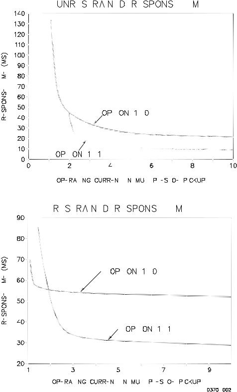
Timing |
|
Refer to Figure 1-3 for Unrestrained Response Times and |
|||||||||||||||||||||||||||||||||||||||||||||||||||||||||||||||||||||||||||
(For 60 Hz units only) |
|
Restrained Response Times. |
|||||||||||||||||||||||||||||||||||||||||||||||||||||||||||||||||||||||||||
|
|
|
|
|
|
|
|
|
|
|
|
|
|
|
|
|
|
|
|
|
|
|
|
|
|
|
|
|
|
|
|
|
|
|
|
|
|
|
|
|
|
|
|
|
|
|
|
|
|
|
|
|
|
|
|
|
|
|
|
|
|
|
|
|
|
|
|
||||||||||
|
|
|
|
|
|
|
|
|
|
|
|
|
|
|
|
|
|
|
|
|
|
|
|
|
|
|
|
|
|
|
|
|
|
|
|
|
|
|
|
|
|
|
|
|
|
|
|
|
|
|
|
|
|
|
|
|
|
|
|
|
|
|
|
|
|
|
|
|
|
|
|
|
|
|
|
|
|
|
|
|
|
|
|
|
|
|
|
|
|
|
|
|
|
|
|
|
|
|
|
|
|
|
|
|
|
|
|
|
|
|
|
|
|
|
|
|
|
|
|
|
|
|
|
|
|
|
|
|
|
|
|
|
|
|
|
|
|
|
|
|
|
|
|
|
|
|
|
|
|
|
|
|
|
|
|
|
|
|
|
|
|
|
|
|
|
|
|
|
|
|
|
|
|
|
|
|
|
|
|
|
|
|
|
|
|
|
|
|
|
|
|
|
|
|
|
|
|
|
|
|
|
|
|
|
|
|
|
|
|
|
|
|
|
|
|
|
|
|
|
|
|
|
|
|
|
|
|
|
|
|
|
|
|
|
|
|
|
|
|
|
|
|
|
|
|
|
|
|
|
|
|
|
|
|
|
|
|
|
|
|
|
|
|
|
|
|
|
|
|
|
|
|
|
|
|
|
|
|
|
|
|
|
|
|
|
|
|
|
|
|
|
|
|
|
|
|
|
|
|
|
|
|
|
|
|
|
|
|
|
|
|
|
|
|
|
|
|
|
|
|
|
|
|
|
|
|
|
|
|
|
|
|
|
|
|
|
|
|
|
|
|
|
|
|
|
|
|
|
|
|
|
|
|
|
|
|
|
|
|
|
|
|
|
|
|
|
|
|
|
|
|
|
|
|
|
|
|
|
|
|
|
|
|
|
|
|
|
|
|
|
|
|
|
|
|
|
|
|
|
|
|
|
|
|
|
|
|
|
|
|
|
|
|
|
|
|
|
|
|
|
|
|
|
|
|
|
|
|
|
|
|
|
|
|
|
|
|
|
|
|
|
|
|
|
|
|
|
|
|
|
|
|
|
|
|
|
|
|
|
|
|
|
|
|
|
|
|
|
|
|
|
|
|
|
|
|
|
|
|
|
|
|
|
|
|
|
|
|
|
|
|
|
|
|
|
|
|
|
|
|
|
|
|
|
|
|
|
|
|
|
|
|
|
|
|
|
|
|
|
|
|
|
|
|
|
|
|
|
|
|
|
|
|
|
|
|
|
|
|
|
|
|
|
|
|
|
|
|
|
|
|
|
|
|
|
|
|
|
|
|
|
|
|
|
|
|
|
|
|
|
|
|
|
|
|
|
|
|
|
|
|
|
|
|
|
|
|
|
|
|
|
|
|
|
|
|
|
|
|
|
|
|
|
|
|
|
|
|
|
|
|
|
|
|
|
|
|
|
|
|
|
|
|
|
|
|
|
|
|
|
|
|
|
|
|
|
|
|
|
|
|
|
|
|
|
|
|
|
|
|
|
|
|
|
|
|
|
|
|
|
|
|
|
|
|
|
|
|
|
|
|
|
|
|
|
|
|
|
|
|
|
|
|
|
|
|
|
|
|
|
|
|
|
|
|
|
|
|
|
|
|
|
|
|
|
|
|
|
|
|
|
|
|
|
|
|
|
|
|
|
|
|
|
|
|
|
|
|
|
|
|
|
|
|
|
|
|
|
|
|
|
|
|
|
|
|
|
|
|
|
|
|
|
|
|
|
|
|
|
|
|
|
|
|
|
|
|
|
|
|
|
|
|
|
|
|
|
|
|
|
|
|
|
|
|
|
|
|
|
|
|
|
|
|
|
|
|
|
|
|
|
|
|
|
|
|
|
|
|
|
|
|
|
|
|
|
|
|
|
|
|
|
|
|
|
|
|
|
|
|
|
|
|
|
|
|
|
|
|
|
|
|
|
|
|
|
|
|
|
|
|
|
|
|
|
|
|
|
|
|
|
|
|
|
|
|
|
|
|
|
|
|
|
|
|
|
|
|
|
|
|
|
|
|
|
|
|
|
|
|
|
|
|
|
|
|
|
|
|
|
|
|
|
|
|
|
|
|
|
|
|
|
|
|
|
|
|
|
|
|
|
|
|
|
|
|
|
|
|
|
|
|
|
|
|
|
|
|
|
|
|
|
|
|
|
|
|
|
|
|
|
|
|
|
|
|
|
|
|
|
|
|
|
|
|
|
|
|
|
|
|
|
|
|
|
|
|
|
|
|
|
|
|
|
|
|
|
|
|
|
|
|
|
|
|
|
|
|
|
|
|
|
|
|
|
|
|
|
|
|
|
|
|
|
|
|
|
|
|
|
|
|
|
|
|
|
|
|
|
|
|
|
|
|
|
|
|
|
|
|
|
|
|
|
|
|
|
|
|
|
|
|
|
|
|
|
|
|
|
|
|
|
|
|
|
|
|
|
|
|
|
|
|
|
|
|
|
|
|
|
|
|
|
|
|
|
|
|
|
|
|
|
|
|
|
|
|
|
|
|
|
|
|
|
|
|
|
|
|
|
|
|
|
|
|
|
|
|
|
|
|
|
|
|
|
|
|
|
|
|
|
|
|
|
|
|
|
|
|
|
|
|
|
|
|
|
|
|
|
|
|
|
|
|
|
|
|
|
|
|
|
|
|
|
|
|
|
|
|
|
|
|
|
|
|
|
|
|
|
|
|
|
|
|
|
|
|
|
|
|
|
|
|
|
|
|
|
|
|
|
|
|
|
|
|
|
|
|
|
|
|
|
|
|
|
|
|
|
|
|
|
|
|
|
|
|
|
|
|
|
|
|
|
|
|
|
|
|
|
|
|
|
|
|
|
|
|
|
|
|
|
|
|
|
|
|
|
|
|
|
|
|
|
|
|
|
|
|
|
|
|
|
|
|
|
|
|
|
|
|
|
|
|
|
|
|
|
|
|
|
|
|
|
|
|
|
|
|
|
|
|
|
|
|
|
|
|
|
|
|
|
|
|
|
|
|
|
|
|
|
|
|
|
|
|
|
|
|
|
|
|
|
|
|
|
|
|
|
|
|
|
|
|
|
|
|
|
|
|
|
|
|
|
|
|
|
|
|
|
|
|
|
|
|
|
|
|
|
|
|
|
|
|
|
|
|
|
|
|
|
|
|
|
|
|
|
|
|
|
|
|
|
|
|
|
|
|
|
|
|
|
|
|
|
|
|
|
|
|
|
|
|
|
|
|
|
|
|
|
|
|
|
|
|
|
|
|
|
|
|
|
|
|
|
|
|
|
|
|
|
|
|
|
|
|
|
|
|
|
|
|
|
|
|
|
|
|
|
|
|
|
|
|
|
|
|
|
|
|
|
|
|
|
|
|
|
|
|
|
|
|
|
|
|
|
|
|
|
|
|
|
|
|
|
|
|
|
|
|
|
|
|
|
|
|
|
|
|
|
|
|
|
|
|
|
|
|
|
|
|
|
|
|
|
|
|
|
|
|
|
|
|
|
|
|
|
|
|
|
|
|
|
|
|
|
|
|
|
|
|
|
|
|
|
|
|
|
|
|
|
|
|
|
|
|
|
|
|
|
|
|
|
|
|
|
|
|
|
|
|
|
|
|
|
|
|
|
|
|
|
|
|
|
|
|
|
|
|
|
|
|
|
|
|
|
|
|
|
|
|
|
|
|
|
|
|
|
|
|
|
|
|
|
|
|
|
|
|
|
|
|
|
|
|
|
|
|
|
|
|
|
|
|
|
|
|
|
|
|
|
|
|
|
|
|
|
|
|
|
|
|
|
|
|
|
|
|
|
|
|
|
|
|
|
|
|
|
|
|
|
|
|
|
|
|
|
|
|
|
|
|
|
|
|
|
|
|
|
|
|
|
|
|
|
|
|
|
|
|
|
|
|
|
|
|
|
|
|
|
|
|
|
|
|
|
|
|
|
|
|
|
|
|
|
|
|
|
|
|
|
|
|
|
|
|
|
|
|
|
|
|
|
|
|
|
|
|
|
|
|
|
|
|
|
|
|
|
|
|
|
|
|
|
|
|
|
|
|
|
|
|
|
|
|
|
|
|
|
|
|
|
|
|
|
|
|
|
|
|
|
|
|
|
|
|
|
|
|
|
|
|
|
|
|
|
|
|
|
|
|
|
|
|
|
|
|
|
|
|
|
|
|
|
|
|
|
|
|
|
|
|
|
|
|
|
|
|
|
|
|
|
|
|
|
|
|
|
|
|
|
|
|
|
|
|
|
|
|
|
|
|
|
|
|
|
|
|
|
|
|
|
|
|
|
|
|
|
|
|
|
|
|
|
|
|
|
|
|
|
|
|
|
|
|
|
|
|
|
|
|
|
|
|
|
|
|
|
|
|
|
|
|
|
|
|
|
|
|
|
|
|
|
|
|
|
|
|
|
|
|
|
|
|
|
|
|
|
|
|
|
|
|
|
|
|
|
|
|
|
|
|
|
|
|
|
|
|
|
|
|
|
|
|
|
|
|
|
|
|
|
|
|
|
|
|
|
|
|
|
|
|
|
|
|
|
|
|
|
|
|
|
|
|
|
|
|
|
|
|
|
|
|
|
|
|
|
|
|
|
|
|
|
|
|
|
|
|
|
|
|
|
|
|
|
|
|
|
|
|
|
|
|
|
|
|
|
|
|
|
|
|
|
|
|
|
|
|
|
|
|
|
|
|
|
|
|
|
|
|
|
|
|
|
|
|
|
|
|
|
|
|
|
|
|
|
|
|
|
|
|
|
|
|
|
|
|
|
|
|
|
|
|
|
|
|
|
|
|
|
|
|
|
|
|
|
|
|
|
|
|
|
|
|
|
|
|
|
|
|
|
|
|
|
|
|
|
|
|
|
|
|
|
|
|
|
|
|
|
|
|
|
|
|
|
|
|
|
|
|
|
|
|
|
|
|
|
|
|
|
|
|
|
|
|
|
|
|
|
|
|
|
|
|
|
|
|
|
|
|
|
|
|
|
|
|
|
|
|
|
|
|
|
|
|
|
|
|
|
|
|
|
|
|
|
|
|
|
|
|
|
|
|
|
|
|
|
|
|
|
|
|
|
|
|
|
|
|
|
|
|
|
|
|
|
|
|
|
|
|
|
|
|
|
|
|
|
|
|
|
|
|
|
|
|
|
|
|
|
|
|
|
|
|
|
|
|
|
|
|
|
|
|
|
|
|
|
|
|
|
|
|
|
|
|
|
|
|
|
|
|
|
|
|
|
|
|
|
|
|
|
|
|
|
|
|
|
|
|
|
|
|
|
|
|
|
|
|
|
|
|
|
|
|
|
|
|
|
|
|
|
|
|
|
|
|
|
|
|
|
|
|
|
|
|
|
|
|
|
|
|
|
|
|
|
|
|
|
|
|
|
|
|
|
|
|
|
|
|
|
|
|
|
|
|
|
|
|
|
|
|
|
|
|
|
|
|
|
|
|
|
|
|
|
|
|
|
|
|
|
|
|
|
|
|
|
|
|
|
|
|
|
|
|
|
|
|
|
|
|
|
|
|
|
|
|
|
|
|
|
|
|
|
|
|
|
|
|
|
|
|
|
|
|
|
|
|
|
|
|
|
|
|
|
|
|
|
|
|
|
|
|
|
|
|
|
|
|
|
|
|
|
|
|
|
|
|
|
|
|
|
|
|
|
|
|
|
|
|
|
|
|
|
|
|
|
|
|
|
|
|
|
|
|
|
|
|
|
|
|
|
|
|
|
|
|
|
|
|
|
|
|
|
|
|
|
|
|
|
|
|
|
|
|
|
|
|
|
|
|
|
|
|
|
|
|
|
|
|
|
|
|
|
|
|
|
|
|
|
|
|
|
|
|
|
|
|
|
|
|
|
|
|
|
|
|
|
|
|
|
|
|
|
|
|
|
|
|
|
|
|
|
|
|
|
|
|
|
|
|
|
|
|
|
|
|
|
|
|
|
|
|
|
|
|
|
|
|
|
|
|
|
|
|
|
|
|
|
|
|
|
|
|
|
|
|
|
|
|
|
|
|
|
|
|
|
|
|
|
|
|
|
|
|
|
|
|
|
|
|
|
|
|
|
|
|
|
|
|
|
|
|
|
|
|
|
|
|
|
|
|
|
|
|
|
|
|
|
|
|
|
|
|
|
|
|
|
|
|
|
|
|
|
|
|
|
|
|
|
|
|
|
|
|
|
|
|
|
|
|
|
|
|
|
|
|
|
|
|
|
|
|
|
|
|
|
|
|
|
|
|
|
|
|
|
|
|
|
|
|
|
|
|
|
|
|
|
|
|
|
|
|
|
|
|
|
|
|
|
|
|
|
|
|
|
|
|
|
|
|
|
|
|
|
|
|
|
|
|
|
|
|
|
|
|
|
|
|
|
|
|
|
|
|
|
|
|
|
|
|
|
|
|
|
|
|
|
|
|
|
|
|
|
|
|
|
|
|
|
|
|
|
|
|
|
|
|
|
|
|
|
|
|
|
|
|
|
|
|
|
|
|
|
|
|
|
|
|
|
|
|
|
|
|
|
|
|
|
|
|
|
|
|
|
|
|
|
|
|
|
|
|
|
|
|
|
|
|
|
|
|
|
|
|
|
|
|
|
|
|
|
|
|
|
|
|
|
|
|
|
|
|
|
|
|
|
|
|
|
|
|
|
|
|
|
|
|
|
|
|
|
|
|
|
|
|
|
|
|
|
|
|
|
|
|
|
|
|
|
|
|
|
|
|
|
|
|
|
|
|
|
|
|
|
|
|
|
|
|
|
|
|
|
|
|
|
|
|
|
|
|
|
|
|
|
|
|
|
|
|
|
|
|
|
|
|
|
|
|
|
|
|
|
|
|
|
|
|
|
|
|
|
|
|
|
|
|
|
|
|
|
|
|
|
|
|
|
|
|
|
|
|
|
|
|
|
|
|
|
|
|
|
|
|
|
|
|
|
|
|
|
|
|
|
|
|
|
|
|
|
|
|
|
|
|
|
|
|
|
|
|
|
|
|
|
|
|
|
|
|
|
|
|
|
|
|
|
|
|
|
|
|
|
|
|
|
|
|
|
|
|
|
|
|
|
|
|
|
|
|
|
|
|
|
|
|
|
|
|
|
|
|
|
|
|
|
|
|
|
|
|
|
|
|
|
|
|
|
|
|
|
|
|
|
|
|
|
|
|
|
|
|
|
|
|
|
|
|
|
|
|
|
|
|
|
|
|
|
|
|
|
|
|
|
|
|
|
|
|
|
|
|
|
|
|
|
|
|
|
|
|
|
|
|
|
|
|
|
|
|
|
|
|
|
|
|
|
|
|
|
|
|
|
|
|
|
|
|
|
|
|
|
|
|
|
|
|
|
|
|
|
|
|
|
|
|
|
|
|
|
|
|
|
|
|
|
|
|
|
|
|
|
|
|
|
|
|
|
|
|
|
|
|
|
|
|
|
|
|
|
|
|
|
|
|
|
|
|
|
|
|
|
|
|
|
|
|
|
|
|
|
|
|
|
|
|
|
|
|
|
|
|
|
|
|
|
|
|
|
|
|
|
|
|
|
|
|
|
|
|
|
|
|
|
|
|
|
|
|
|
|
|
|
|
|
|
|
|
|
|
|
|
|
|
|
|
|
|
|
|
|
|
|
|
|
|
|
|
|
|
|
|
|
|
|
|
|
|
|
|
|
|
|
|
|
|
|
|
|
|
|
|
|
|
|
|
|
|
|
|
|
|
|
|
|
|
|
|
|
|
|
|
|
|
|
|
|
|
|
|
|
|
|
|
|
|
|
|
|
|
|
|
|
|
|
|
|
|
|
|
|
|
|
|
|
|
|
|
|
|
|
|
|
|
|
|
|
|
|
|
|
|
|
|
|
|
|
|
|
|
|
|
|
|
|
|
|
|
|
|
|
|
|
|
|
|
|
|
|
|
|
|
|
|
|
|
|
|
|
|
|
|
|
|
|
|
|
|
|
|
|
|
|
|
|
|
|
|
|
|
|
|
|
|
|
|
|
|
|
|
|
|
|
|
|
|
|
|
|
|
|
|
|
|
|
|
|
|
|
|
|
|
|
|
|
|
|
|
|
|
|
|
|
|
|
|
|
|
|
|
|
|
|
|
|
|
|
|
|
|
|
|
|
|
|
|
|
|
|
|
|
|
|
|
|
|
|
|
|
|
|
|
|
|
|
|
|
|
|
|
|
|
|
|
|
|
|
|
|
|
|
|
|
|
|
|
|
|
|
|
|
|
|
|
|
|
|
|
|
|
|
|
|
|
|
|
|
|
|
|
|
|
|
|
|
|
|
|
|
|
|
|
|
|
|
|
|
|
|
|
|
|
|
|
|
|
|
|
|
|
|
|
|
|
|
|
|
|
|
|
|
|
|
|
|
|
|
|
|
|
|
|
|
|
|
|
|
|
|
|
|
|
|
|
|
|
|
|
|
|
|
|
|
|
|
|
|
|
|
|
|
|
|
|
|
|
|
|
|
|
|
|
|
|
|
|
|
|
|
|
|
|
|
|
|
|
|
|
|
|
|
|
|
|
|
|
|
|
|
|
|
|
|
|
|
|
|
|
|
|
|
|
|
|
|
|
|
|
|
|
|
|
|
|
|
|
|
|
|
|
|
|
|
|
|
|
|
|
|
|
|
|
|
|
|
|
|
|
|
|
|
|
|
|
|
|
|
|
|
|
|
|
|
|
|
|
|
|
|
|
|
|
|
|
|
|
|
|
|
|
|
|
|
|
|
|
|
|
|
|
|
|
|
|
|
|
|
|
|
|
|
|
|
|
|
|
|
|
|
|
|
|
|
|
|
|
|
|
|
|
|
|
|
|
|
|
|
|
|
|
|
|
|
|
|
|
|
|
|
|
|
|
|
|
|
|
|
|
|
|
|
|
|
|
|
|
|
|
|
|
|
|
|
|
|
|
|
|
|
|
|
|
|
|
|
|
|
|
|
|
|
|
|
|
|
|
|
|
|
|
|
|
|
|
|
|
|
|
|
|
|
|
|
|
|
|
|
|
|
|
|
|
|
|
|
|
|
|
|
|
|
|
|
|
|
|
|
|
|
|
|
|
|
|
|
|
|
|
|
|
|
|
|
|
|
|
|
|
|
|
|
|
|
|
|
|
|
|
|
|
|
|
|
|
|
|
|
|
|
|
|
|
|
|
|
|
|
|
|
|
|
|
|
|
|
|
|
|
|
|
|
|
|
|
|
|
|
|
|
|
|
|
|
|
|
|
|
|
|
|
|
|
|
|
|
|
|
|
|
|
|
|
|
|
|
|
|
|
|
|
|
|
|
|
|
|
|
|
|
|
|
|
|
|
|
|
|
|
|
|
|
|
|
|
|
|
|
|
|
|
|
|
|
|
|
|
|
|
|
|
|
|
|
|
|
|
|
|
|
|
|
|
|
|
|
|
|
|
|
|
|
|
|
|
|
|
|
|
|
|
|
|
|
|
|
|
|
|
|
|
|
|
|
|
|
|
|
|
|
|
|
|
|
|
|
|
|
|
|
|
|
|
|
|
|
|
|
|
|
|
|
|
|
|
|
|
|
|
|
|
|
|
|
|
|
|
|
|
|
|
|
|
|
|
|
|
|
|
|
|
|
|
|
|
|
|
|
|
|
|
|
|
|
|
|
|
|
|
|
|
|
|
|
|
|
|
|
|
|
|
|
|
|
|
|
|
|
|
|
|
|
|
|
|
|
|
|
|
|
|
|
|
|
|
|
|
|
|
|
|
|
|
|
|
|
|
|
|
|
|
|
|
|
|
|
|
|
|
|
|
|
|
|
|
|
|
|
|
|
|
|
|
|
|
|
|
|
|
|
|
|
|
|
|
|
|
|
|
|
|
|
|
|
|
|
|
|
|
|
|
|
|
|
|
|
|
|
|
|
|
|
|
|
|
|
|
|
|
|
|
|
|
|
|
|
|
|
|
|
|
|
|
|
|
|
|
|
|
|
|
|
|
|
|
|
|
|
|
|
|
|
|
|
|
|
|
|
|
|
|
|
|
|
|
|
|
|
|
|
|
|
|
|
|
|
|
|
|
|
|
|
|
|
|
|
|
|
|
|
|
|
|
|
|
|
|
|
|
|
|
|
|
|
|
|
|
|
|
|
|
|
|
|
|
|
|
|
|
|
|
|
|
|
|
|
|
|
|
|
|
|
|
|
|
|
|
|
|
|
|
|
|
|
|
|
|
|
|
|
|
|
|
|
|
|
|
|
|
|
|
|
|
|
|
|
|
|
|
|
|
|
|
|
|
|
|
|
|
|
|
|
|
|
|
|
|
|
|
|
|
|
|
|
|
|
|
|
|
|
|
|
|
|
|
|
|
|
|
|
|
|
|
|
|
|
|
|
|
|
|
|
|
|
|
|
|
|
|
|
|
|
|
|
|
|
|
|
|
|
|
|
|
|
|
|
|
|
|
|
|
|
|
|
|
|
|
|
|
|
|
|
|
|
|
|
|
|
|
|
|
|
|
|
|
|
|
|
|
|
|
|
|
|
|
|
|
|
|
|
|
|
|
|
|
|
|
|
|
|
|
|
|
|
|
|
|
|
|
|
|
|
|
|
|
|
|
|
|
|
|
Figure 1-3. Unrestrained Response Times and Restrained Response Times
1-8 |
BE1-87T General Information |
9171300990 Rev V |
Isolation |
In accordance with IEC 255-5 and ANSI/IEEE C37.90-1989, |
|||
|
one minute dielectric (high potential) tests, as follows: |
|||
|
All circuits to ground: 2,121 Vdc |
|
||
|
Input to output circuits: 1,500 Vac or 2,121 Vdc |
|
||
Power Supply |
Refer to Table 1-3. |
|
|
|
|
Table 1-3. Power Supply Ratings |
|
||
|
|
|
|
|
Type |
Nominal |
Input Voltage Range |
Burden at |
|
Input Voltage |
Nominal |
|||
|
|
|||
K (midrange) |
48 Vdc |
24 to 150 Vdc |
9.0 W |
|
|
|
|
|
|
J (midrange) |
125 Vdc |
24 to 150 Vdc |
9.0 W |
|
|
|
|
||
120 Vac |
90 to 132 Vac |
21.0 VA |
||
|
||||
|
|
|
|
|
L (low range) |
24 Vdc |
12 to 32 Vdc * |
9.0 W |
|
|
|
|
|
|
Y (midrange) |
48 Vdc |
24 to 150 Vdc |
8.5 W |
|
|
|
|
||
125 Vdc |
24 to 150 Vdc |
9.0 W |
||
|
||||
|
|
|
|
|
Z (high range) |
250 Vdc |
68 to 280 Vdc |
9.5 W |
|
|
|
|
||
240 Vac |
90 to 270 Vac |
28.0 VA |
||
|
||||
|
|
|
|
|
* Type L power supply initially requires 14 Vdc to begin operating. Once operating, the input voltage may be reduced to 12 Vdc and operation will continue.
Surge Withstand Capability |
Qualified to ANSI/IEEE C37.90.1-1989, Standard Surge |
|
Withstand Capability (SWC) Tests for Protective Relays and |
|
Relay Systems, and IEC 255-5 Impulse Test and Dielectric |
|
Test. |
Radio Frequency Interference |
Maintains proper operation when tested in accordance with |
(RFI) |
IEEE C37.90.2-1987, Trial-Use Standard Withstand |
|
Capability of Relay Systems to Radiated Electromagnetic |
|
Interference from Transceivers. |
UL Recognition |
UL Recognized per Standard 508, UL File No. E97033. Note: |
|
Output contacts are not UL Recognized for voltages greater |
|
than 250 V. |
GOST-R Certification |
GOST-R certified per the relevant standards of Gosstandart |
|
of Russia. |
Patent |
Patented in U.S., 1991, U.S. Patent No. 5014153. |
|
Patented in Canada, 1993. |
Shock |
In standard tests, the relay has withstood 15 g in each of |
|
three mutually perpendicular axes without structural damage |
|
or degradation of performance. |
Vibration |
In standard tests, the relay has withstood 2 g in each of three |
|
mutually perpendicular axes swept over the range of 10 to |
|
500 Hz for a total of six sweeps, 15 minutes each sweep, |
|
without structural damage or degradation of performance. |
Operating Temperature |
–40°C (–40°F) to 70°C (158°F) |
Storage Temperature |
–65°C (–85°F) to 100°C (212°F) |
9171300990 Rev V |
BE1-87T General Information |
1-9 |
Weight |
22.3 lbs (10.1 kg) maximum (three-phase unit) |
|
19.5 lbs (8.85 kg) maximum (single-phase unit) |
Case Size |
All units are supplied in an M1 case size. See Section 4, |
|
Installation for case dimensions. |
1-10 |
BE1-87T General Information |
9171300990 Rev V |
SECTION 2 • CONTROLS AND INDICATORS
TABLE OF CONTENTS
SECTION 2 • CONTROLS AND INDICATORS ........................................................................................ |
2-1 |
Location of Controls and Indicators ....................................................................................................... |
2-1 |
Figures
Figure 2-1. Sensing Input Range 1 or 3 Three-Phase, Three Inputs ........................................................ |
2-4 |
|
Figure 2-2. |
Sensing Input Range 1 or 3, Single-Phase, Five Inputs ......................................................... |
2-5 |
Figure 2-3. |
Sensing Input Range 2 or 4, Three-Phase, Two Inputs.......................................................... |
2-6 |
Figure 2-4. Controls Mounted Inside the Relay......................................................................................... |
2-7 |
|
Figure 2-5. |
Sensing Input Range 2 or 4, Option 1-1, Single-Phase, Five Inputs, % OF TRIP Option...... |
2-8 |
Tables
Table 2-1. Controls and Indicators ............................................................................................................ |
2-1 |
9171300990 Rev V |
BE1-87T Controls and Indicators |
i |

|
|
|
|
|
|
|
|
ii |
|
BE1-87T Controls and Indicators |
9171300990 Rev V |

SECTION 2 • CONTROLS AND INDICATORS
Location of Controls and Indicators
Table 2-1 lists and briefly describes the operator controls and indicators of the BE1-87T Transformer Differential Relay. Reference the call-out letters A through M to Figures 2-1 to 2-3; N through Q to Figure 2-5. Exploded views of controls that are mounted inside the relay (call-out letters B, D and I) are shown in Figure 2-4.
Table 2-1. Controls and Indicators
Letter |
Control or Indicator |
Function |
A |
INPUT (or TAP) Switches |
Front panel INPUT switches are used to scale the |
|
|
transformer currents. There are two of these rotary |
|
|
switches for each input. |
|
1 Ampere CT Units |
Each of the upper switches is calibrated to represent |
|
|
the tenths and units digits (0.4 through 1.6) of tap |
|
|
value. Each of the lower switches is calibrated to |
|
|
represent two-hundredths of tap value for each |
|
|
increment. Always add the setting of the lower switch to |
|
|
that of the upper switch. For example, if a setting of |
|
|
1.02 is desired, the upper switch must be at 1.0 and the |
|
|
lower switch must be at 0.02. The total setting range for |
|
|
each input is 0.4 to 1.78. |
|
5 Ampere CT Units |
Each of the upper switches is calibrated to represent |
|
|
the units digit (2 through 8) of tap value. Each of the |
|
|
lower switches is calibrated to represent tenths of tap |
|
|
value. Always add the setting of the lower switch to that |
|
|
of the upper switch. For example, if a setting of 5.0 is |
|
|
desired, the upper switch is set to 5.0, the lower switch |
|
|
must be at 0.0. The total setting range for each input is |
|
|
2.0 to 8.9. |
B |
30° Phase Shift Jumpers |
These jumpers control the internal phase shift of the |
|
(three-phase units ONLY) |
relay, either +30°, -30°, or 0°, depending upon the |
|
|
position of the jumpers provided for each input on the |
|
|
Analog #2 Board, shown in Figure 2-4. Additional |
|
|
information is in Section 4. |
C |
UNRESTRAINED PICKUP |
This thumbwheel switch establishes the desired pickup |
|
LEVEL Switches |
setting for all phases of the unrestrained output. The |
|
|
adjustment range is from 6 to 21 times the phase tap |
|
|
setting, in increments of 1. |
D |
CALIBRATE Switch |
A two-position switch is located on each Analog #1 |
|
(three-phase units ONLY) |
Board and is easily accessible on the right side of the |
|
|
relay when it is withdrawn from the case. In the |
|
|
CALIBRATE position, these switches inhibit the |
|
|
harmonic share feature when calibrating the 2nd |
|
|
Harmonic Restraint. In the NORMAL position, the relay |
|
|
will operate normally. |
|
|
|
E |
POWER Indicator |
This LED will illuminate when operating power is |
|
|
supplied to the internal circuitry of the relay. |
9171300990 Rev V |
BE1-87T Controls and Indicators |
2-1 |
Letter |
Control or Indicator |
Function |
F |
PUSH-TO-ENERGIZE |
Two momentary pushbutton switches are accessible by |
|
OUTPUT Switches Option |
inserting a 1/8 inch diameter non-conducting rod |
|
|
through access holes in the front panel. Switch R, |
|
|
when actuated, closes the Restrained Output Relay |
|
|
contacts. Switch U, when actuated, closes the |
|
|
Unrestrained Output Relay contact(s). |
|
|
NOTE |
|
|
The optional Auxiliary Relay contacts (Option 3-1, 3-2 |
|
|
or 3-5) will also be operated by the PUSH-TO- |
|
|
ENERGIZE switches if enabled by the two internal |
|
|
Auxiliary Relay Control Switches. (Refer to LETTER I.) |
G |
FUNCTION Targets Option |
Electronically-latched LED targets that indicate an |
|
|
unrestrained or restrained output has occurred. |
H |
Target Reset Switch |
Resets the electronically-latched targets. |
I |
Auxiliary Relay Control |
Two internal slide switches, S1 and S2, enable the |
|
Switches Option |
optional Auxiliary Output Relay to close only when a |
|
|
restrained output occurs (S1 ON), only when an |
|
|
unrestrained output occurs (S2 ON), or to close when |
|
|
either output occurs (S1 and S2 ON). |
|
|
When shipped from the factory, the Auxiliary Relay will |
|
|
be configured with S1 and S2 ON. |
|
|
NOTE |
|
|
The switches are located on the mother board and are |
|
|
only accessible by withdrawing the relay case. |
J |
ELEMENT Targets Option |
Electronically-latching LED targets indicate the phase |
|
(three-phase units ONLY) |
that caused a trip operation. |
K |
RESTRAINED PICKUP |
Thumb-wheel switches (one per phase element) are |
|
LEVEL Switches |
used to adjust the desired percent of allowable |
|
|
through-current restraint from 15 to 60 % in 5 % |
|
|
increments. (Through-current is the greatest relative |
|
|
individual input current.) |
|
|
The through-current restraint characteristic is |
|
|
individually adjustable for phases A, B, and C. |
|
|
In a three-phase unit, all three switches are typically |
|
|
kept at identical settings. |
L |
UNREST. TRIP Indicator |
Red LED lights when there is an unrestrained pickup. |
M |
REST. TRIP Indicator |
Red LED lights when there is a restrained pickup. |
N |
M Indicator |
Red LED lights when the % OF TRIP pushbutton P is |
|
|
pressed and the restraint current is below the slope |
|
|
characteristic kneepoint as defined in Table 1-1. That |
|
|
is, the relay will operate at minimum pickup (0.35 times |
|
|
tap). |
O |
S Indicator |
Red LED lights when the % OF TRIP pushbutton P is |
|
|
pressed and the restraint current is above the slope |
|
|
characteristic kneepoint as defined in Table 1-1. That |
|
|
is, the relay will operate based on the restraint |
|
|
characteristic. |
P |
Percent of Trip Pushbutton |
Pushbutton that is used to activate the % of TRIP |
|
|
LEDs. |
2-2 |
BE1-87T Controls and Indicators |
9171300990 Rev V |
Letter |
Control or Indicator |
|
|
Function |
Q |
% OF TRIP Indicators Option |
When the % OF TRIP pushbutton P is pushed, eight |
||
|
|
LEDs, shown in Figure 2-5, are used to indicate the |
||
|
|
approximate percentage of operating current to: |
||
|
|
Minimum pickup (LED M also lights); or |
||
|
|
Slope characteristic pickup (LED S also lights). |
||
|
|
The eight LEDs represent the following approximate |
||
|
|
percentages. |
|
|
|
|
1 LED: |
3% (Yellow LED) |
|
|
|
2 LEDs: |
7% (Yellow LED) |
|
|
|
3 LEDs: |
11% |
(Yellow LED) |
|
|
4 LEDs: |
20% |
(Red LED) |
|
|
5 LEDs: |
40% |
(Red LED) |
|
|
6 LEDs: |
60% |
(Red LED) |
|
|
7 LEDs: |
80% |
(Red LED) |
|
|
8 LEDs: 100% (Red LED) |
||
|
|
A bar chart above the LEDs shows the relative |
||
|
|
percentage of trip. |
|
|
9171300990 Rev V |
BE1-87T Controls and Indicators |
2-3 |

Figure 2-1. Sensing Input Range 1 or 3 Three-Phase, Three Inputs
2-4 |
BE1-87T Controls and Indicators |
9171300990 Rev V |

Figure 2-2. Sensing Input Range 1 or 3, Single-Phase, Five Inputs
9171300990 Rev V |
BE1-87T Controls and Indicators |
2-5 |
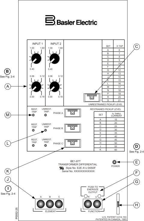
Figure 2-3. Sensing Input Range 2 or 4, Three-Phase, Two Inputs
2-6 |
BE1-87T Controls and Indicators |
9171300990 Rev V |
Loading...