

Page 1
www.basler.com
+1 618.654.2341 (USA)
info@basler.com
INTRODUCTION
BE3-32 reverse power relays monitor the direction of power
flow from ac generators. Single-phase or three-phase, threewire units are available. If current flow from the generator
becomes reversed and exceeds the adjustab le sett ing, the
relay will trip. BE3-32 relays can prevent generator motoring
due to a loss of prime mover torque. An adjustable DELAY
control is provided to avoid tripping caused by transients
encountered during synchronization. A RELAY LED
indicates output relay status. The POWER LED indicates
the condition of the power supply.
SPECIFICATIONS
Inputs
All units are self powered.
Nominal Voltage: 120 Vac, 240 Vac, 380 Vac, or
480 Vac
Current Sensing: 5 Aac nominal
Frequency: 50, 60, or 400 Hz
Burden
Voltage: Less than 3 VA
Current: Less than 0.5 VA
Overload Withstand
Voltage: 1.25 times nominal continuously.
2 times nominal for 3 seconds.
Current: 2 times nominal continuously.
10 times nominal for 3 seconds.
Setpoint
Range: Adjustable 2 to 20%, (±3%) of
nominal, of reverse current
Repeatability: Better than 0.5% of full span
Time Delay: Adjustable 0 to 20 sec
Hysteresis: 1% of nominal
Outputs
Relay Type: D.P.D.T.
AC Rating: 250 V, 5 A, non-resistive,
1200 VA
DC Rating: 125 V, 1 A, resistive, 120 W
Mechanical Life: 5 million operations
Temperature
Operating Temperature: 0°C (32°F) to 60°C (140°F)
Functional Temperature: –25°C (–13°F) to 70°C (158°F)
Storage Temperature: –40°C (–40°F) to 70°C (158°F)
Temperature Coefficient: 0.03% per °C (300 ppm/°C)
Humidity
Relative Humidity: 95% non-condensing
Model
Physical
Mounting: DIN rail 1.38” by 0.29” (35 mm by
Case: Complies with IEC 529, DIN
Case Material: Complies with UL 94VO
Weight: 1.32 lb (0.6 kg)
Size: 3.94” wide (100 mm)
Agency
cULus Listed to UL 508 and CSA C22.2 No. 14
CE compliant
GOST-R certified per the relevant standards of Gosstandart
of Russia
BE3-32
7.5 mm)
40050, BS 5490
OPERATION
BE3-32 reverse power relays have two external, useradjustable controls marked SET and DELAY. The SET
control adjusts the point at which the relay trips when
reverse current flow is detected. The SET control is
adjustable from 2% (0.1 A) to 20% (1.0 A) of nominal (5 A).
Setpoint range accuracy is ±3% of nominal. When the
reverse power setting is exceeded, the output relay
energizes and the red RELAY LED lights. The green
POWER LED indicates the condition of the power supply.
The DELAY control adjusts the time between when the
reverse power setpoint is exceeded and the outp ut relay
energizes. The DELAY control setting range is 0 to 20
seconds.
Setting Example
A BE3-32 relay has the following settings:
• SET - 10%
• DELAY - 10 seconds
The relay begins timing toward a trip when 0.5 A of reverse
current flow is detected. The output relay trips 10 seconds
after the reverse current threshold is excee ded.
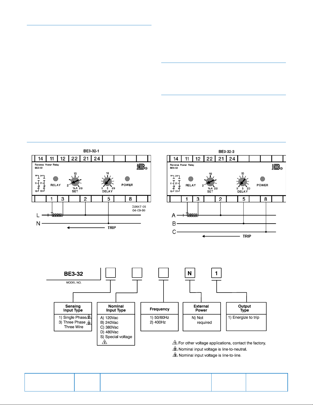
INSTALLATION
BE3 reverse power relays are designed for mounting on
standard DIN rails that comply to DIN-EN 50022. Mounting
involves hooking the top edge of the cutout on the base of
the case over one edge of the DIN rail. The opposite side of
the cutout containing the release clip is then pushed over
the opposite side of the DIN rail. To remove or reposition the
relay, lever the release clip and move the relay as required.
BE3 relays should be installed in a dry, vibration-free
location where the ambient temperature does not exceed
the operating temperature range. Connections to the relay
should be made using wire that meets applicable codes and
is properly sized for the application. Figure 1 shows the
terminal connections for the BE3-32 relay.
Publication
9319800990
Revision
F
Instructions
Date
04/14
Copyright
2014
Page 2
CALIBRATION
The calibration marks on the faceplate have a maximum
error of 10% and are provided only as guides. Proper
calibration requires using an accurate meter to monitor the
current. Use the following procedure to calibrate your relay.
Setpoint
1. Adjust the SET control fully clockwise and the DELAY
control fully counterclockwise.
2. Apply nominal input voltage to the relay. Apply the
desired value of trip current to the relay. The
connections for the current should be reversed to
simulate reverse power.
3. Slowly adjust the SET control counterclockwise until the
relay trips.
Delay
1. Set the DELAY control at the desired time setting.
2. Apply nominal input voltage to the relay.
FIGURES
3. Apply a value of reverse current that is greater than the
relay trip point. Measure the time from when the current
is applied until the relay trips.
4. Compare the measured time to the desired time delay
and adjust the DELAY control accordingly.
5. Repeat Steps 3 and 4 as required.
MAINTENANCE
BE3 relays are solid-state devices that require no
maintenance. In the event that your relay requires repair,
contact Basler Electric, Highland, IL, USA for return
authorization.
ORDERING INFORMATION
Figure 2 shows the BE3 reverse power relay style numbers.
• BE3-32-1: Single-Phase Reverse Power
• BE3-32-3: Three-Phase Reverse Power
Publication
9319800990
Figure 1. BE3-32-1, BE3-32-3 Reverse Power Relay Connections
Figure 2. BE3-32-1, BE3-32-3 Style Number Identification Chart
Revision
F
Instructions
Date
04/14
Page
2 of 2
 Loading...