

Basler Electric BE1-CDS240 Installation

SECTION 12 • INSTALLATION
TABLE OF CONTENTS
SECTION 12 • INSTALLATION .............................................................................................................. 12-1
General ................................................................................................................................................ 12-1
Contact-Sensing Input Jumpers........................................................................................................... 12-1
Trip Coil Monitor (TCM) Jumpers ........................................................................................................ 12-2
Mounting .............................................................................................................................................. 12-2
Relay Connections ............................................................................................................................. 12-10
Terminal Blocks .............................................................................................................................. 12-10
Typical AC and DC Connections .................................................................................................... 12-13
CT Polarity ...................................................................................................................................... 12-18
Power System Applications ............................................................................................................... 12-19
Settings .............................................................................................................................................. 12-24
Preparing the Relay for Service ......................................................................................................... 12-24
Communications Connections ........................................................................................................... 12-24
RS-232 Connectors ........................................................................................................................ 12-24
RS-485 Connectors ........................................................................................................................ 12-26
IRIG Input and Connections ........................................................................................................... 12-27
Figures
Figure 12-1. Contact-Sensing and TCM Jumper Locations .................................................................... 12-2
Figure 12-2. Vertical Panel Mount, M-size, Front View ........................................................................... 12-3
Figure 12-3. Vertical Panel Mount, M-size, Side View or Horizontal Panel Mount, Top View ................ 12-4
Figure 12-4. Vertical Panel Mount, M-size, Top View, or Horizontal Panel Mount Side View ................ 12-4
Figure 12-5. Vertical Panel or Horizontal Panel Mount MX Case, Panel Drilling Diagram ..................... 12-5
Figure 12-6. Horizontal Rack Mount, Front View .................................................................................... 12-6
Figure 12-7. Horizontal Rack Mount, Top View ....................................................................................... 12-7
Figure 12-8. Horizontal Rack Mount, Side View ...................................................................................... 12-7
Figure 12-9. Vertical Panel Mount, L-size, Front View ............................................................................ 12-8
Figure 12-10. Vertical Panel Mount, L-size, Top View ............................................................................ 12-9
Figure 12-11. Vertical Panel Mount, L-size, Side View ........................................................................... 12-9
Figure 12-12. Horizontal Panel Mount, Front View ............................................................................... 12-10
Figure 12-13. Horizontal or Vertical Rear View Terminal Connections (I/O Option "A" Shown) ........... 12-11
Figure 12-14. Horizontal or Vertical Rear View Terminal Connections (I/O Option "E" Shown) ........... 12-12
Figure 12-15. Typical AC Connection, 3-Restraint Windings, 2-IG Inputs with Voltage Protection ...... 12-14
Figure 12-16. Typical AC Connection, 4-Restraint Windings, 1-IG without Voltage Protection ............ 12-15
Figure 12-17. Typical Application, Two-winding, Transformer with 4-Restraint Connections ............... 12-16
Figure 12-18. Typical DC Connection Diagrams ................................................................................... 12-17
Figure 12-19. Standard CT Polarity ....................................................................................................... 12-18
Figure 12-20. Current Transformer Action ............................................................................................ 12-18
Figure 12-21. Example of Reversed CT Polarity ................................................................................... 12-18
Figure 12-22. Voltage Sensing, Alternate VTP Input ............................................................................ 12-19
Figure 12-23. BE1-CDS240 Connected for Primary Protection, BE1-851 Connected for Independent
Backup ............................................................................................................................................ 12-20
Figure 12-24. BE1-CDS240 Percentage Differential Bus Protection .................................................... 12-21
Figure 12-25. Typical Connection for Motor, Generator, or Reactor Differential Protection ................. 12-22
Figure 12-26. CDS 240 Large Generator Protection - BE1-CDS240 Connected for Primary Current
Differential, Voltage and Frequency Protection and Metering; BE1-GPS100 Connected for
Independent Backup Fault Protection, Detection of Abnormal Situations and Backup Monitoring 12-23
Figure 12-27. RS-232 Pinouts ............................................................................................................... 12-25
Figure 12-28. Personal Computer to BE1-CDS240 .............................................................................. 12-25
Figure 12-29. Modem to BE1-CDS240 ................................................................................................. 12-25
Figure 12-30. RFL9660 Protective Relay Switch to BE1-CDS240 Cable ............................................. 12-26
Figure 12-31. SEL 2020/2030 to BE1-CDS240 Relay .......................................................................... 12-26
Figure 12-32. RS-485 DB-37 to BE1-CDS240 ...................................................................................... 12-27
9365200990 Rev M BE1-CDS240 Installation i

Tables
Table 12-1. Contact-Sensing Turn-On Voltages ..................................................................................... 12-1
Table 12-2. RS-232 Pinouts (COM0 and COM1) .................................................................................. 12-24
Table 12-3. RS-485 Pinouts (COM 2) ................................................................................................... 12-26
Table 12-4. IRIG Terminal Assignments ............................................................................................... 12-27
ii BE1-CDS240 Installation 9365200990 Rev M

SECTION 12 • INSTALLATION
General
BE1-CDS240 Current Differential Systems are delivered with an instruction manual and BESTCOMS™
software in a sturdy carton to prevent shipping damage. Upon receipt of the relay, check the model and
style number against the requisition and packaging list for agreement. If there is evidence of shipping
damage, file a claim with the carrier, and notify the Basler Electric Regional Sales Office, your sales
representative, or a sales representative at Basler Electric, Highland, Illinois.
If the BE1-CDS240 is not installed immediately, store it in the original shipping package in a moisture and
dust free environment.
Contact-Sensing Input Jumpers
NOTE
The BE1-CDS240 relays with mid- or high-range power supplies are delivered
with the jumpers in the H (HIGH) position. Read the following paragraphs
before placing the relay in service.
BE1-CDS240 relays have eight or twelve contact-sensing inputs, depending on style number, to initiate
relay actions. An external wetting voltage is required for the contact-sensing inputs. The nominal voltage
level of the external dc source must comply with the dc power supply input voltage ranges listed in
Section 1, General Information, Specifications. To enhance user flexibility, the BE1-CDS240 uses wide
range ac/dc power supplies that cover several common control voltages. The contact sensing input
circuits are designed to respond to voltages at the lower end of the control voltage range while not
overheating at the high end of the range.
Energizing levels for the contact-sensing inputs are jumper selectable for a minimum of approximately 5
Vdc for 24 Vdc nominal sensing voltage, 26 Vdc for 48 Vdc nominal sensing voltages, or 69 Vdc for 125
Vdc nominal sensing voltages. See Table 12-1 for the contact-sensing turn-on voltages.
Table 12-1. Contact-Sensing Turn-On Voltages
Style
Option
xxxx1xxxxxx 48 Vdc or 125 Vac/dc 26 to 38 Vdc
xxxx2xxxxxx 125/250 Vac/dc
xxxx3xxxxxx 24 Vdc n/a n/a Approx. 5 Vdc
* AC voltage ranges are calculated using the default recognition time (4 ms) and debounce time (16 ms).
Each BE1-CDS240 with a mid- or high-range power supply is delivered with the contact-sensing jumpers
installed (H position) for operation in the higher end of the control voltage range. If the contact-sensing
inputs are to be operated at the lower end of the control voltage range, the jumpers must be changed to L
position.
The following paragraphs describe how to locate and remove/change the contact sensing input jumpers.
1. Remove the drawout assembly by pulling the two latches outward and sliding the assembly out of
the case. Observe all electrostatic discharge (ESD) precautions when handling the drawout
assembly.
9365200990 Rev M BE1-CDS240 Installation 12-1
Nominal Input
Voltage
Jumper (L)
(Low Position)
69 to 100 Vdc
56 to 97 Vac
Contact-Sensing Turn-On Voltage *
Jumper (H)
(High Position)
69 to 100 Vdc
56 to 97 Vac
138 to 200 Vdc
112 to 194 Vac
Jumper Not
Installed
n/a
n/a
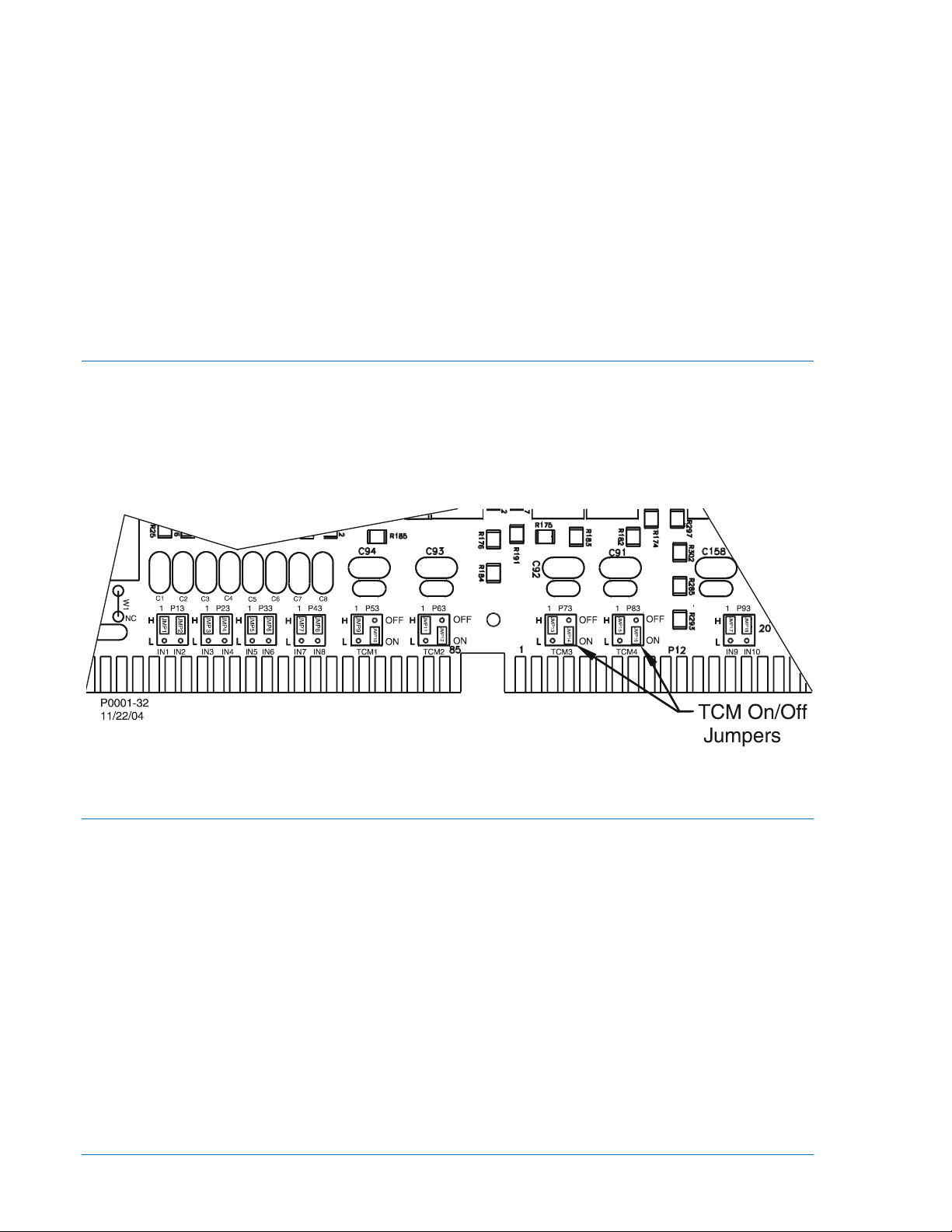
2. Locate the eight jumper terminal blocks (or 12, Option A) that are mounted on the Input/Output
Circuit Board. The Input/Output Circuit Board is the middle board in the assembly and the jumper
terminal blocks are located on the back edge on the component side of the circuit board. Each
terminal block has three pins. With the jumper as installed at the factory, one pin should be visible
when viewed from the rear of the unit. Figure 12-1 illustrates the location of the jumpers placed in
the high voltage position.
3. To select operation at the lower end of the control voltage range, position the blue jumper on the
two terminals closest to the rear of the circuit board (L). Use care when removing each jumper so
that no components are damaged.
4. When all jumpers are positioned for operation in the desired control voltage range, prepare to
place the drawout assembly back into the case.
5. Align the drawout assembly with the case guides and slide the assembly into the case.
6. Push the latches down until they are parallel with the front panel.
Trip Coil Monitor (TCM) Jumpers
BE1-CDS240 relays have four trip coil monitor circuits for monitoring up to four breaker trip coils. Each
TCM includes a High/Low Input jumper and a TCM On/Off jumper. The High/Low jumper establishes the
operate voltage level of the Input as explained above and the On/Off jumper enables or disables the TCM
logic. The TCMs are associated with Outputs 7, 8, 9, and 10. Relays are shipped with the jumpers in the
TCM ON (active) position. To move the jumper to the off position, follow the procedure outlined under
Contact Sensing Input Jumpers and look for the terminals labeled TCM as shown on Figure 12-1.
Figure 12-1. Contact-Sensing and TCM Jumper Locations
Mounting
Because the unit is of solid-state design, it does not have to be mounted vertically. Any convenient
mounting angle may be chosen. BE1-CDS240 Overcurrent Protection Systems are available in Basler
Electric's MX case design. MX cases are fully drawout with current circuit shorting provisions. MX cases
are available in four configurations: a standard 19-inch rack horizontal mount, a horizontal panel mount,
and two vertical panel mounts (I/O Option "A" and I/O Option "E"). The short vertical panel mount
configuration fits cutout and panel drilling dimensions of Basler Electric M1, GE M1 and M2, and
Westinghouse FT31 and FT32 size cases. The long vertical mounting pane fits cutout and drilling
dimensions of the GE L2 and Westinghouse FT42 cases.
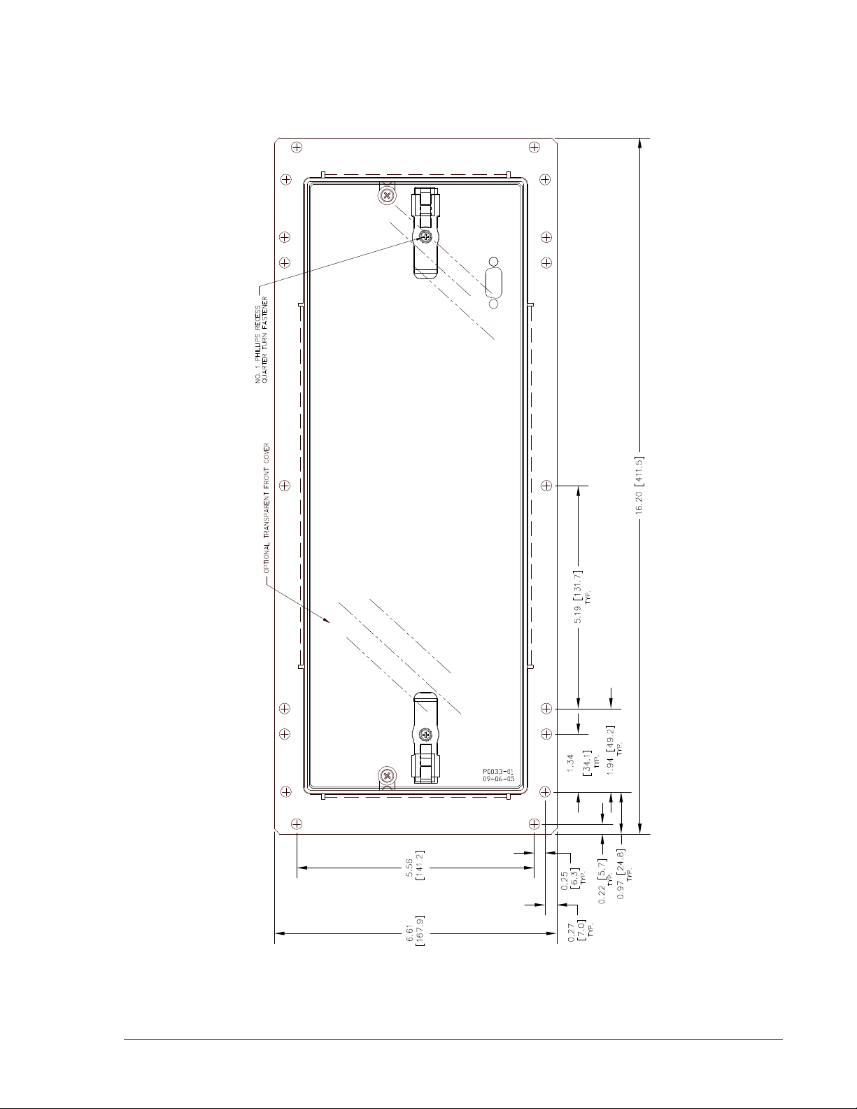
• Figures 12-2 through 12-4 show the overall dimensions of the case with vertical panel mounting
or horizontal panel mounting, M-size.
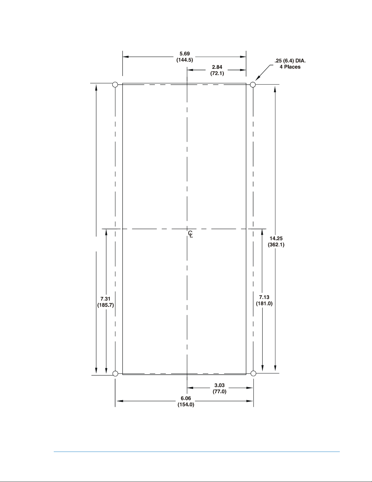
• Figure 12-5 is the panel-drilling diagram for the vertical panel mount or horizontal mount, MX
case.
• Figures 12-6 through 12-8 show the overall dimensions of the case with the horizontal rack
mounting.
• Figures 12-9 through 12-11 show the overall dimensions of the case with the vertical panel
mounting, L-size.
12-2 BE1-CDS240 Installation 9365200990 Rev M
• Figure 12-12 shows the front dimensions for the horizontal panel mount case.
• Vertical and horizontal configurations are functionally the same with some controls and indicators
relocated. All drawing dimensions are listed in inches and millimeters.
Figure 12-2. Vertical Panel Mount, M-size, Front View
9365200990 Rev M BE1-CDS240 Installation 12-3
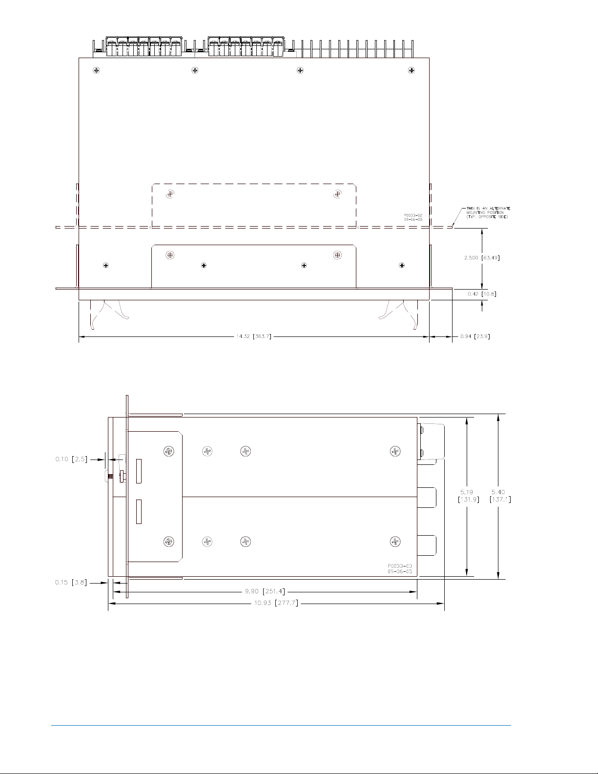
Figure 12-3. Vertical Panel Mount, M-size, Side View or Horizontal Panel Mount, Top View
Figure 12-4. Vertical Panel Mount, M-size, Top View, or Horizontal Panel Mount Side View
12-4 BE1-CDS240 Installation 9365200990 Rev M
14.63
P0069-74
(371.6)
Figure 12-5. Vertical Panel or Horizontal Panel Mount MX Case, Panel Drilling Diagram
9365200990 Rev M BE1-CDS240 Installation 12-5
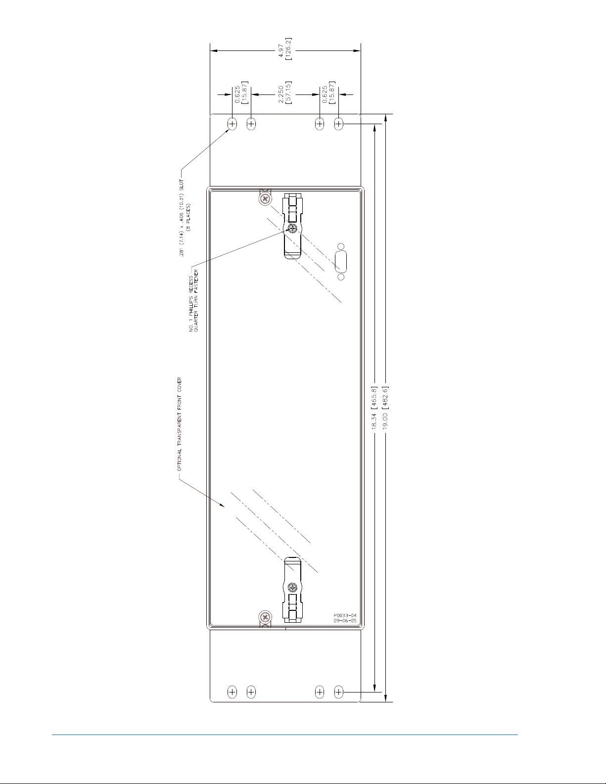
Figure 12-6. Horizontal Rack Mount, Front View
12-6 BE1-CDS240 Installation 9365200990 Rev M
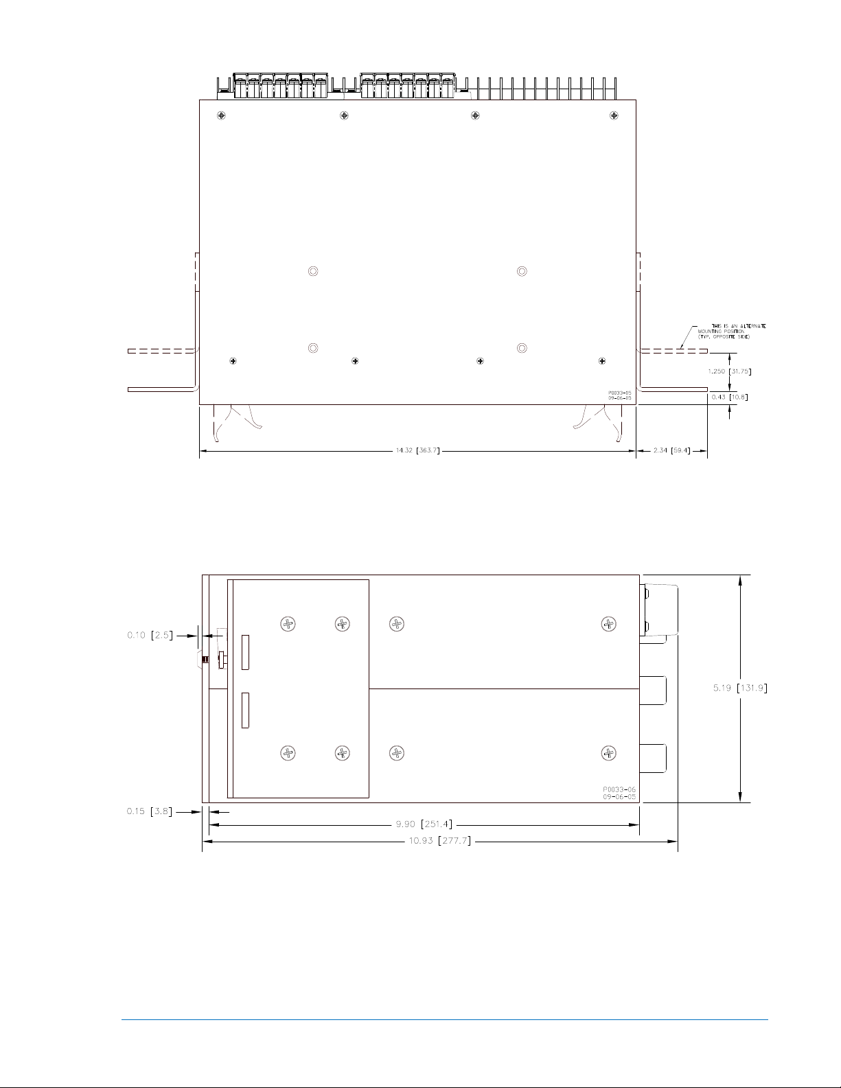
Figure 12-7. Horizontal Rack Mount, Top View
Figure 12-8. Horizontal Rack Mount, Side View
9365200990 Rev M BE1-CDS240 Installation 12-7
 Loading...