

Page 1

SECTION 2 • QUICK START
TABLE OF CONTENTS
SECTION 2 • QUICK START .................................................................................................................... 2-1
General .................................................................................................................................................. 2-1
About This Manual ............................................................................................................................. 2-1
Section................................................................................................................................................ 2-1
BESTlogic .............................................................................................................................................. 2-1
Characteristics of Protection and Control Elements .......................................................................... 2-2
Element Logic Settings ....................................................................................................................... 2-3
Output Logic Settings ......................................................................................................................... 2-3
User Interfaces ....................................................................................................................................... 2-3
Front Panel HMI ................................................................................................................................. 2-3
ASCII Command Communications .................................................................................................... 2-4
BESTCOMS™ for BE1-CDS240, Graphical User Interface ............................................................... 2-5
Getting Started ....................................................................................................................................... 2-6
Connections ....................................................................................................................................... 2-6
Entering Test Settings ........................................................................................................................ 2-6
Checking the State of Inputs .............................................................................................................. 2-7
Testing ................................................................................................................................................ 2-7
FAQ/Troubleshooting ............................................................................................................................. 2-7
Frequently Asked Questions (FAQs) ................................................................................................. 2-7
Figures
Figure 2-1. 87 Phase Differential Element ................................................................................................ 2-2
Figure 2-2. 51 HMI Screen ........................................................................................................................ 2-4
Tables
Table 2-1. Function Categories and Manual Sections Cross-Reference .................................................. 2-1
Table 2-2. Trip LED Truth Table ................................................................................................................ 2-9
9365200990 Rev M BE1-CDS240 Quick Start i
Page 2

ii BE1-CDS240 Quick Start 9365200990 Rev M
Page 3

SECTION 2 • QUICK START
Section
Input and Output Functions
3
Protection and Control
4
Metering
5
Reporting and Alarm Functions
6
BESTlogic Programmable Logic
7
Application
8
General
This section provides an overview of the BE1-CDS240 Current Differential System. You should be familiar
with the concepts behind the user interfaces and BESTlogic before you begin reading about the detailed
BE1-CDS240 functions. Sections 3 through 6 in this manual describe in detail each function of the BE1CDS240.
The following information is intended to provide the reader with a basic understanding of the three user
interfaces (front panel human-machine interface (HMI), ASCII serial communications link, and the
BESTCOMS™ for BE1-CDS240 software) and the security features provided in the BE1-CDS240 relay.
Detailed information on the operation of the HMI (human-machine interface) is in Section 10, and the
information on ASCII command communications is in Section 11. BESTCOMS is a Windows® based
software application (graphical user interface) that enhances communication between the PC user and
the BE1-CDS240 relay. BESTCOMS for the BE1-CDS240 is provided free of charge with the BE1CDS240 and details are provided in Section 14.
Also covered in this section is an overview of BESTlogic. BESTlogic is a highly flexible programmable
logic system that allows the user to apply the available functions with complete flexibility and customize
the system to meet the requirements of the protected power system. Detailed information on using
BESTlogic to design complete protection and control schemes for the protected circuit can be found in
Section 7, BESTlogic Programmable Logic, and Section 8, Application.
Sections 3 through 6 describe each function provided in the BE1-CDS240 relay and include references to
the following items. Note that not all items are appropriate for each function.
• Human-machine interface (HMI) screens for setting the operational parameters.
• BESTCOMS for setting the operational parameters.
• BESTCOMS for setting up the BESTlogic required for functions in your protection and control
scheme.
• Outputs from the function such as alarm and BESTlogic variables or data reports.
• HMI screens for operation or interrogation of the outputs and reports provided by each function.
• ASCII commands for operation or interrogation of the outputs and reports provided by each function.
About This Manual
The various application functions provided by this multifunction relay are divided into four functional
categories: input/output functions, protection and control functions, metering functions, and reporting and
alarm functions. Detailed descriptions of each individual function, setup, and use are covered in the
Sections as shown in Table 2-1. Detailed information on using programmable logic to create your
protection and control scheme is described in Section 7, BESTlogic Programmable Logic.
Table 2-1. Function Categories and Manual Sections Cross-Reference
Section Title
BESTlogic
Each of the protection and control elements in the BE1-CDS240 is implemented as an independent
function that is equivalent to a single function, discrete device counterpart. Each independent element
has all of the inputs and outputs that the discrete component counterpart might have. Programming
BESTlogic is equivalent to choosing the devices required by your protection and control scheme and
drawing schematic diagrams to connect the inputs and outputs to obtain the desired operational logic.
9365200990 Rev M BE1-CDS240 Quick Start 2-1
Page 4
The concept is the same but the method is different in that you choose each element by enabling it and
use Boolean logic expressions to connect the inputs and outputs. The result is that you have even greater
flexibility in designing your system than you had using discrete devices. An added benefit is that you are
not constrained by the limitations in flexibility inherent in many multifunction relays.
One user programmable, custom logic scheme created by the user may be programmed and saved in
memory. Or, the user may choose from one preprogrammed logic scheme embedded in the relay
firmware or several preprogrammed logic schemes in the BESTCOMS logic library that can be copied to
the relay. Preprogrammed schemes can reduce or eliminate the need for programming by the user.
Preprogrammed logic settings can also be modified after being saved in the relay. This provides a good
starting point for a custom logic scheme. To modify the preprogrammed scheme, it is necessary to enter a
unique name for the new logic before modifying the settings. Naming the new logic distinguishes it from
the preprogrammed logic scheme. In the 16 character preprogrammed logic name, the last 4 characters
refer to revision A, dash (-), and BE (Basler Electric). When customizing a programmed logic scheme, it is
recommended that the user include the revision level of their scheme and change the BE to a 2-digit code
representative of the user's company name. For example, if VA Power were modifying the CDS240BATX-A-BE the preprogrammed logic scheme might be CDS240-BATX-B-VP, the B standing for revision
level B, and VP for VA Power.
There are two types of BESTlogic settings: element (function block) logic settings and output logic
settings. These will be described briefly in the following paragraphs. Detailed information on using
BESTlogic to design complete protection and control schemes for the protected circuit can be found in
Section 7, BESTlogic Programmable Logic and Section 8, Application.
Characteristics of Protection and Control Elements
As stated before, each element (function block) is equivalent to a discrete device counterpart. For
example, the transformer differential element in the BE1-CDS240 relay has all of the characteristics of a
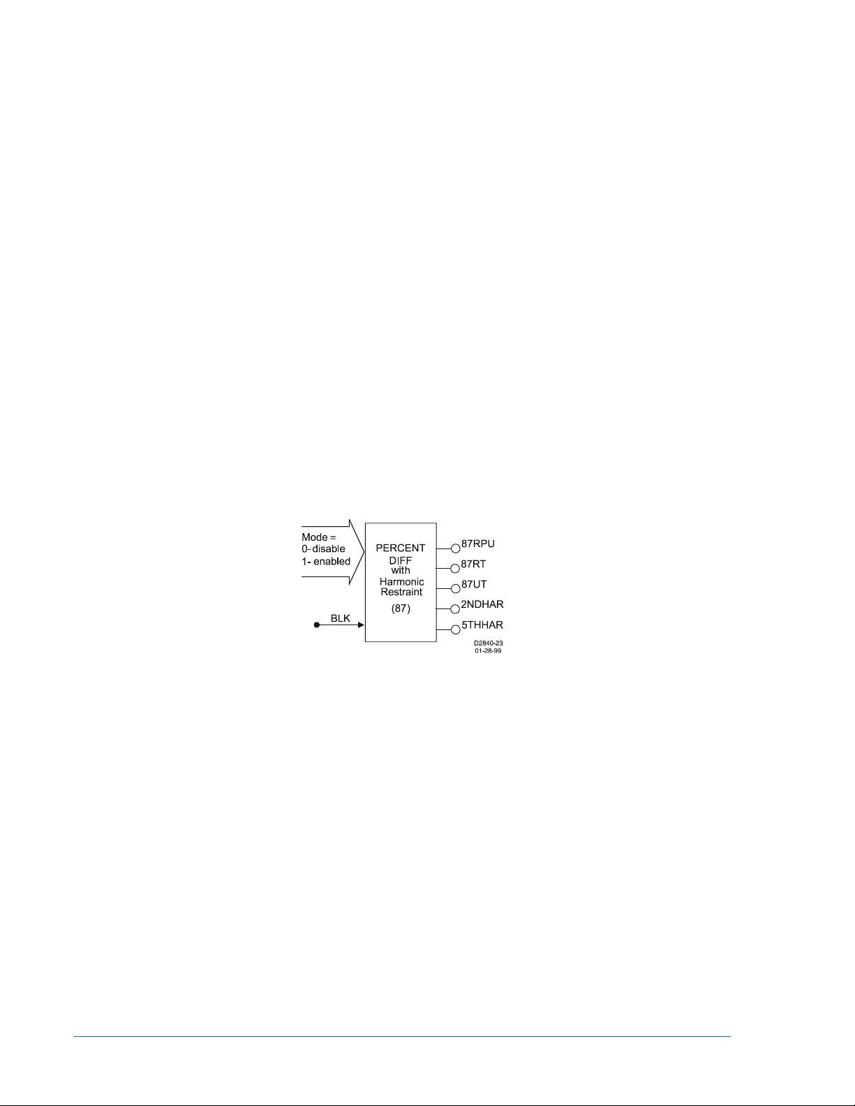
version of the BE1-87T transformer differential relay with similar functionality. Figure 2-1 shows the 87
phase differential element inputs and outputs.
Figure 2-1. 87 Phase Differential Element
Two inputs:
• Mode (enable/disable 87 operation)
• BLK (block 87 operation)
Five outputs:
• 87RPU (87 Restrained Pickup)
• 87RT (87 Restrained Trip)
• 87UT (87 Unrestrained Trip)
nd
• 2NDHAR (2
• 5THHAR (5
Harmonic Inhibit Status)
th
Harmonic Inhibit Status)
Five operational settings:
• Minimum pickup
• Slope
nd
Harmonic Inhibit
• 2
th
Harmonic Inhibit
• 5
• Unrestrained Pickup
Of the above characteristics, the five operational settings are not included in the logic settings. They are
included in the protection settings. This is an important distinction. Since changing logic settings is similar
to rewiring a panel, the logic settings are separate and distinct from the operational settings such as
pickups and time delays.
2-2 BE1-CDS240 Quick Start 9365200990 Rev M
Page 5

Element Logic Settings
To use a protection or control element, two items need to be set. These are the mode and the input logic.
The mode is equivalent to deciding which devices you want to install in your protection and control
scheme. You then must set the logic variables that will be connected to the inputs.
For example, the 51N element has two modes (disabled and enabled), and one input, block (torque
control). To use this element, the logic setting command might be SL-51N=1,/IN2 for Set Logic-51N to be
Mode 1 (enabled) with the element blocked when contact sensing Input 2 is not (/) energized. Contact
Sensing Input 2 would be wired to a ground relay enable switch.
As noted before, the protection settings for this element, pickup, time dial, and curve, must be set
separately in the setting group settings. The setting might be S0-51N=6.5,2.1,S1R for Set in Setting
Group 0 - the 51N function = to pickup at 6.5 amps with a time dial of 2.1 using curve S1 with an
integrating reset characteristic.
The 51N element has two logic output variables, 51NT (Trip) and 51NPU (Picked Up). The combination of
the logic settings and the operational settings for the element govern how these variables respond to logic
and current inputs.
Output Logic Settings
BESTlogic, as implemented in the BE1-CDS240, supports up to 16 output expressions. The output
expressions are called virtual outputs to distinguish them from the physical output relays. In the BE1CDS240, any virtual output (VO1 through VO16) can drive any physical output relay (OUT1 through
OUT14). VOA is different in that it will always drives physical output relay, Out A which is the fail safe
alarm output. Other virtual outputs may be assigned to or removed from OUTA, but VOA will always drive
OUTA. In addition, any of the virtual outputs can be used for intermediate logic expressions.
For example, OUT1 is wired to the trip bus of a circuit breaker. To set up the logic to trip the breaker, the
BESTlogic setting command might be SL-VO1=VO11+101T+BFPU for Set Logic - Virtual Output 1 = to
Virtual Output 11 (which is the intermediate logic expression for all of the element tripping outputs) or (+)
101T (the trip output of the virtual breaker control switch) or (+) BFPU (the pickup output of the breaker
failure element that indicates that breaker failure has been initiated). To assign this to OUT1, the
BESTlogic command would be SL-OUT1=VO1.
User Interfaces
Three user interfaces are provided for interacting with the BE1-CDS240 relay: the front panel HMI, ASCII
communications, and the BESTCOMS for BE1-CDS240 software. The front panel HMI provides access to
a subset of the total functionality of the device. ASCII communications provides access to all settings,
controls, reports, and metering functionality of the system. The BESTCOMS for BE1-CDS240 software
provides a Windows based, user-friendly environment for editing settings files and uploading and
downloading them from the relay (see Section 14 for details).
Front Panel HMI
The front panel HMI consists of a two line by a 16 character LCD (liquid crystal display) with four scrolling
pushbuttons, an edit pushbutton, and a reset pushbutton. The EDIT pushbutton includes an LED to
indicate when edit mode is active. There are five other LEDs for indicating power supply status, relay
trouble alarm status, programmable major and minor alarm status, and a multipurpose Trip LED that
flashes to indicate that a protective element is picked up. The Trip LED lights continuously when the trip
output is energized and seals in when a protective trip has occurred to indicate that target information is
being displayed on the LCD. A complete description of the HMI is included in Section 10, Human-Machine
Interface.
The BE1-CDS240 HMI is menu driven and organized into a menu tree structure with six branches. A
complete menu tree description with displays is also provided in Section 10, Human-Machine Interface. A
list of the menu branches and a brief description for scrolling through the menu is in the following
paragraphs.
1. REPORT STATUS. Display and resetting of general status information such as targets, alarms,
recloser status, etc.
2. CONTROL. Operation of manual controls such as virtual switches, selection of active setting
group, etc.
3. METERING. Display of real time metering values.
9365200990 Rev M BE1-CDS240 Quick Start 2-3
Page 6

4. REPORTS. Display and resetting of report information such as time and date, demand registers,
breaker duty statistics, etc.
5. PROTECTION. Display and setting of protective function setting parameters such as logic
scheme, pickups, time delays, etc.
6. GENERAL SETTINGS. Display and setting of non-protective function setting parameters such as
communications, LCD contrast, and CT ratio.
Each screen in the menu tree displays the path in the upper left hand corner of the screen. Additionally,
each screen is assigned a number in the HMI section. The path indicates the branch and level in the
menu tree structure. This path should help you to keep track of where you are when you leave the menu
tree top level. You scroll through each level of the menu tree by using the right and left scrolling
pushbuttons. To go to a level of detail, you use the down scrolling pushbutton. Each time you go to a
lower level in the menu tree, another string is added to the path and separated by a backslash.
For example, to check or change the 51N pickup setting in Setting Group 3, you would press the right or
left scrolling pushbuttons to get to Screen \PROT - PROTECTION. You would then press the down
scrolling pushbutton to get to the next level of detail and the right or left scrolling pushbutton to get to
Screen \PROT\SG3 - SETTING GROUP 3. To continue, you would press the down and then the right or
left scrolling pushbuttons to get to Screen \PROT\SG3\51 INVERSE TIME OVERCURRENT and then
Screen \PROT\SG3\51\51 - 51 Settings. On the screen shown in Figure 2-2, the pickup, time dial and
curve settings for the 51P/N/Q functions can be read and/or edited. To return to the top level from this
location, you would press the Up scrolling pushbutton three times.
Figure 2-2. 51 HMI Screen
ASCII Command Communications
The BE1-CDS240 relay has three independent communications ports for serial communications. Basler
Terminal in BESTCOMS can be connected to any of the three ports so that the user may send commands
to the relay. Alternatively, a computer terminal or PC running a terminal emulation program such as
Windows Terminal can be used in the same manner. Communication with the relay uses a simple ASCII
command language. When a command is entered via a serial port, the relay responds with the
appropriate action. The ASCII command communications is designed for use in both human-to-machine
interactions and in batch download type operations. The following paragraphs briefly describe the
command structure and then discuss human-to-machine interactions and batch command text file
operations for interacting with the relay. The operation of the ASCII commands is described in detail in
Section 11, ASCII Command Interface.
Command Structure
An ASCII command consists of a command string made up of one or two letters followed by a hyphen
and an object name. The first letter specifies the general command function and the second a subgrouping. The object name is the specific function for which the command is intended. If the command
string is entered by itself, it is a read command. If the command string is entered followed by an equal
sign and one or more parameters, it is a write command. The general command groupings are organized
into six major groups plus several miscellaneous commands. These commands are as follows:
C CONTROL. Commands to perform select before operate control actions such as tripping and closing
the circuit breaker, changing the active setting group, etc. Sub-groupings include S for Select and O
for Operate.
G GLOBAL. Perform global operations that do not fall into the other general groupings such as
password security. Sub-groupings include S for security settings.
2-4 BE1-CDS240 Quick Start 9365200990 Rev M
Page 7

M METERING. Read all real time metering values. This general command grouping has no sub-
groupings.
P PROGRAM. Subgroup command to read or program a setting.
R REPORTS. Read and reset reporting functions such as time and date, demand registers, breaker
duty statistics, etc. Sub-groupings include: A for Alarm functions, B for Breaker monitoring functions,
D for Demand recording functions, F for Fault summary reporting functions, G for General
information and S for Sequence of Events recorder functions.
S SETTINGS. Set all setting parameters that govern the functioning of the relay. Sub-groupings
include: 0,1,2,3 for settings in setting groups, A for alarm settings, B for breaker monitoring settings,
G for general settings, L for logic settings.
MISCELLANEOUS. These include Access, Exit, and Help.
Examples of object names would be 51N for the neutral inverse time overcurrent element or PIA for the A
phase, peak current demand register.
For example, to check the 51N pickup setting in Setting Group 3, you would enter S3-51N for Settings,
Group 3-51N. The relay would respond with the current pickup, time dial, and curve settings for the 51N
element. To edit these settings, the same command would be used with an = followed by the new settings
and the enter pushbutton. The user should note that it is necessary to use the Access and Exit
commands when using the write version of these commands.
Human-to-Machine ASCII Command Operations
The ASCII command scheme allows the user to read and/or write settings and operational items on a
function-by-function basis. However, this also requires a great many commands. The mnemonic format of
the commands is designed to facilitate interactive communications with the relay. It is not necessary to
remember all of the object names. Most commands support a multiple read version where it is not
necessary to specify a complete object name. You can enter the first two letters of a command and the
relay will respond with all applicable objects.
For example, you want the relay to report the breaker operations counter reading. You can enter RB for
Report Breaker and the relay will respond with all of the breaker report objects including the operations
counter. If you had remembered that the object name is OPCNTR, you could have entered RB-OPCNTR
and received only the operations counter report. Partial object names are also supported. For example,
you wish to read the entire peak-since-reset demand registers. You can enter RD-PI for Report Demand Peak Current (I) and the relay will respond with the values and time stamps for A, B, C, N and Q. To reset
all five of the peak since reset demand registers, enter the command RD-PI=0. To read only the value for
the neutral demand, the full object name would have been entered (RD-PIN).
Batch Command Text File Operations
With a few exceptions, each function of the relay uses one command to set it and each setting command
operates on all of the parameters required by that element. See the example mentioned above in the
paragraph titled Command Structure. This format results in a great many commands to fully set the relay.
Also, the process of setting the relay does not use a prompting mode where the relay prompts you for
each parameter in turn until you exit the setting process. For these reasons, a method for setting the relay
using batch text files is recommended.
In batch upload type operations, the user creates an ASCII text file of commands and sends it to the
relay. To facilitate this process, the response from a multiple read command is output from the BE1CDS240 in command format. Therefore, the user need only enter S for Set (with no subgroup) and the
relay responds with all of the setting commands and their associated parameters. If the user enters S2 for
Set Group 2, the relay responds with all of the setting commands for Setting Group 2. The user may
capture this response to a file, edit it using any ASCII text editor, and then send the file back to the relay.
See Section 11, ASCII Command Interface, for a more detailed discussion of how to use ASCII text files
for setting the relay.
BESTCOMS™ for BE1-CDS240, Graphical User Interface
Basler Electric's graphical user interface (GUI) software, BESTCOMS, is an alternative method for quickly
developing setting files in a friendly, Windows based environment. Using the GUI, you may prepare
setting files off-line (without being connected to the relay) and then upload the settings to the relay at your
convenience. These settings include protection and control, operational and logic, breaker and
transformer monitoring, metering and fault recording. Engineering personnel can develop, test, and
replicate the settings before exporting it to a file and transmitting the file to technical personnel in the field.
9365200990 Rev M BE1-CDS240 Quick Start 2-5
Page 8

On the field end, the technician simply imports the file into the BESTCOMS database and uploads the file
to the relay where it is stored in nonvolatile memory.
The GUI also has the same preprogrammed logic scheme that is stored in the relay in addition to a library
of additional logic schemes. This gives the engineer the option (off-line) of developing his setting file using
a preprogrammed logic scheme, customizing a preprogrammed logic scheme, or building a scheme from
scratch. Files may be exported from the GUI to a text editor where they can be reviewed or modified. The
modified text file may then be uploaded to the relay. After it is uploaded to the relay, it can be brought into
the GUI, but it cannot be brought directly into the GUI from the text file. The GUI logic builder uses basic
AND/OR gate logic combined with point and click variables to build the logic expressions. This reduces
the design time and increases dependability.
The GUI also allows for downloading industry standard COMTRADE files for analysis of stored
oscillography data. Detailed analysis of the oscillography files may be accomplished using BESTWAVE
software. For more information on Basler Electric's Windows based BESTCOMS (GUI) software, refer to
Section 14, BESTCOMS™ Software.
Getting Started
Connections
Figure 12-25, in Section 12, Installation, shows typical external dc control connections. If your relay has
Power Supply Option 1 or 2, it can be supplied by normal 120 V ac house power. These two power supply
options (1 and 2) are the midrange and high range AC/DC power supplies. The contact sensing inputs are
half-wave rectified opto-isolators. The default contact recognition and debounce settings enable their use
on ac signals as well as dc signals.
Section 12 also shows typical external ac sensing connections. The relay measures the A phase, B
phase, and C phase current magnitudes directly from the three current sensing inputs on Circuit #1 (this
is dependent on style configuration). Circuit #2 measures the A phase, B phase, and C phase current
magnitudes directly from the three current sensing inputs. The neutral and negative-sequence
magnitudes are calculated from the fundamental component of each of the three-phase currents. When
evaluating the negative-sequence functions, the relay can be tested using a two-phase current source. To
fully evaluate the operation of the relay in the power system, it is desirable to use a three-phase current
source.
Connect a computer to the front RS-232 port (refer to Section 12, Installation, for connection diagrams).
Apply power and set the clock using the RG-TIME= and RG-DATE= commands (refer to Appendix C,
Terminal Communication, and Section 11, ASCII Command Interface, for additional information).
Entering Test Settings
Use BESTOMS to enter test settings (see Section 14, BESTCOMS Software, for details) or enter SG (Set
General) to get a listing of the general setting commands with default parameters and put them in a text
file as described previously in Batch Command Text File Operations. Then enter S0 (Setting Group Zero)
to get a listing of the Setting Group 0 protection setting commands with default parameters and put them
in a text file. With these two subgroups of settings, you will not see the global security settings, user
programmable BESTlogic settings, settings for protection Setting Groups 1, 2, and 3, settings for alarm
functions, and the settings for breaker monitoring functions.
Open the SG file in a text editor, change settings as required, and save the changes. For example:
• The ratios for the phase and neutral current transformers (CT2, CTG).
• The demand interval and CT circuit to monitor for the phase, neutral and negative-sequence
currents (DIP, DIN, DIQ).
• The nominal system frequency (FREQ).
• The normal phase-sequence (ABC or ACB) for the system (PHROT).
Open the S0 file in a text editor, change settings, as required, and save the changes. For example:
• The differential taps setting by putting the 87 function in manual and selecting tap values (87).
• The pickup, time dial, and curve for the 51 functions (51P, 51N, 51Q).
While editing this file, it is necessary to set a logic scheme to be active using the SL-N= (Set Protection
LOGIC) command. The default setting is BASIC-87, which means that several protection elements are
2-6 BE1-CDS240 Quick Start 9365200990 Rev M
Page 9

enabled and interconnected but are disabled with settings of zero. See Section 8, Application, for
diagrams that describe the BASIC-87 logic scheme.
Enter A= to gain setting access and then send each of these text files to the relay as described above
under Batch Command Text File Operations. Do not forget to add E;Y (Exit; Save Settings? Yes) to the
end of both files.
As you gain knowledge of the relay, you can experiment with the rest of the settings. To set up a file with
all user settings, enter S and the relay will respond with all settings in command format. The acceptance
test procedure in Section 13, Testing and Maintenance, provides a basic procedure for creating a file with
all user settings.
Checking the State of Inputs
Section 8, Application, shows the Basic Differential (CDS240-BA87-A-BD) logic diagram. Review this
logic to help understand the following discussion. In this scheme, IN1 and IN2 are being used to show the
position of the breakers in the sequence of events record (SER). Input 3 is showing the status of the 86
lockout relay. Inputs 6 to 8 can be used for alarm annunciation. You can quickly review the state of the
inputs in three different ways: one, through the front panel HMI, two, using the ASCII command interface,
or three using BESTCOMS, Metering screen.
The front panel HMI displays the input status on Screen 1.4.1, \STAT\OPER\INPUT. A diagram showing
all of the menu tree branches is located in Section 10, Human-Machine Interface. To get to this screen,
press the Up scrolling pushbutton until you reach the top screen in the current branch. You know when
you have reached the top screen because the screen stops changing when you press the Up scrolling
pushbutton. From this position, press the Right scrolling pushbutton until you have reached the screen
titled, \STATUS BE1-CDS240 REPORT STATUS. From this position, press the Down scrolling
pushbutton one time (\STAT\TARGETS) and press the Right scrolling pushbutton three times. At this
time, you should see the OPERATIONAL STATUS Screen, \STAT\OPER_STAT. If you press the Down
scrolling pushbutton from this screen, you should see the INPUTS Screen, \STAT\OPER\INPUT.
Another method would be to use the ASCII command interface. One command that you can use to see
the status of the inputs is RG-STAT. Another command is RG-INPUT. This command will only read the
status of the inputs and nothing else.
Testing
To determine if the relay is responding correctly to each test, the following commands are useful.
• RG-TARG, (report general targets): reports the targets from the last fault.
• RF, (report faults): reports a directory listing of the twelve fault summary reports. The fault
summary reports are numbered from 1 to 255, then wrap around, and start over. RF-### reports
the ### report.
• RS-##, (report sequence of events record), ## events: reports the most recent ## changes of
state in the protection and control logic.
FAQ/Troubleshooting
Frequently Asked Questions (FAQs)
1.) Will the Trip LED reset after pressing the Reset key on the front panel?
The Reset key is context sensitive. To reset the Trip LED or the targets, the Targets screen
must be displayed. To reset the alarms, the Alarms screen must be displayed.
2.) Is the power supply polarity sensitive?
No, the power supply will accept either an ac or dc voltage input. However, the contact sensing
for the programmable inputs is polarity sensitive. See Section 12, Installation, for a typical interconnection diagram.
9365200990 Rev M BE1-CDS240 Quick Start 2-7
Page 10

3.) What voltage level is used to develop current flow through the contact sensing inputs?
Voltage level is dependent on the power supply option (BE1-CDS240 style) and the position of
the contact-sensing jumper. See Section 12, Installation, for additional information.
4.) How can the BE1-CDS240 be configured into a simple transformer differential relay?
Two preprogrammed schemes perform this function. One is CDS240-BA87-A-BE from the
BESTCOMS logic library (Basic Differential) and the other is the embedded logic scheme
CDS240-BATX-A-BE (Basic Transformer). See Section 8, Application, for additional
information.
5.) How can the BE1-CDS240 be configured into a generator differential relay?
The BE1-CDS240 can be configured into a generator differential relay by loading the
preprogrammed logic scheme CDS240-BA87-A-BE from the BESTCOMS library. You may
disable the 2nd and 5th harmonic functions by setting these thresholds to zero. See Section 8,
Application, for additional information.
6.) Do I have to connect my current transformers in a special way to compensate for the
phase shift between the high side and low side of a transformer?
No, the BE1-CDS240 can compensate for phase shift. See Section 3, Input and Output
Functions, for additional information.
7.) Should I be concerned about zero-sequence blocking in my CT connections?
No, the BE1-CDS240 can compensate for zero-sequence blocking. See Section 3, Input and
Output Functions, for additional information.
8.) Does the BE1-CDS240 trip output contact latch after a fault?
The answer to the question is Yes and No. In general, once the fault goes away the output
contacts open. The BE1-CDS240 does offer an option to ensure that the contact will stay
closed for at least 200 milliseconds. See Section 3, Input and Output Functions, for additional
information on that function. However, BESTlogic can latch the relay outputs. See Section 8,
Application, Application Tips, for additional information.
9.) A function will not work when I put in settings such as the pickup and time delays.
Make sure that the logic function is enabled.
10.) How many overcurrent elements does the BE1-CDS240 have available?
The BE1-CDS240 has seventeen instantaneous overcurrent and thirteen time overcurrent
elements. Just like any element, each of these elements can be assigned to any output for
building logic equations.
11.) Can I make logic settings at the front panel?
No, the front panel cannot program logic settings. Logic settings must be programmed using
the ASCII command interface or BESTCOMS communication software.
12.) Since the BE1-CDS240 is a programmable device, what are the factory defaults?
The factory default logic is BASIC-87 logic. Default settings are shown with each function in the
instruction manual. For input or output default settings see Section 3, Input and Output
Functions. For protection and control functions, see Section 4, Protection and Control.
2-8 BE1-CDS240 Quick Start 9365200990 Rev M
Page 11

13.) Does the BE1-CDS240 have a battery installed as the back-up power source for the
Trip
PU
Targets
LED
0 0 0
Off
0 0 1
On
0 1 0
Flash
internal clock on loss of power?
Yes, as an option. The relay also uses a capacitor as a back-up power source for the internal
clock on loss of power. This design maintains the clock for at least eight hours. See Section 1,
General Information, Specifications, for additional information.
14.) Since the BE1-CDS240 has overcurrent elements in addition to the differential protection
functions, are the timing curves the same as Basler Electric's other numeric overcurrent
relays?
Yes, the timing curves are the same as other Basler Electric numerical overcurrent relays such
as the BE1-851, BE1-951, and BE1-IPS100.
15.) Why do I keep getting access conflict errors when I am communicating with the relay?
If you have tried to gain access to more than one port at a time, an access conflict results. The
unit has three different communication ports. The front HMI and front RS-232 are considered
the same port and are the first port (COM 0). The rear RS-232 (COM 1) is the second and the
rear RS-485 (COM 2) is the third port. If you have gained access at the front panel HMI and the
5-minute timeout has not ended, you cannot gain access at another port. The front RS-232 can
still be accessed because the HMI and front RS-232 are considered the same port. Access
needs to be gained only when a write to the BE1-CDS240 is required (control or setting change
or report reset). Data can be read and reports can be obtained without gaining access. After
gaining access though one of the ports, the session can be ended with the Exit command. If
access is gained, but the session is not ended, a 5-minute timeout will end the session and any
changes that were not saved will be lost. If you are using the BESTCOMS program, the access
and exit commands are executed for you.
16.) Why doesn't the trip LED behave as expected when the relay picks up and trips? A
closely related question would be why don't the targets work?
If the logic is setup to the point were the protective element is tripping at the desired current
level, but the targets, trip LED, and fault records are not behaving as expected, then there are
two commands (SG-TRIGGER and SG-TARGET) that need to be checked for proper
operation. The SG-TRIGGER command needs to have the PU trigger and TRIP trigger logic
correctly programmed. This should initiate the fault record. The SG-TARGET command needs
the protective element (function) enabled to log targets. See Section 6, Reporting and Alarms,
Fault Reporting, to get more details on how to correctly program these commands. The trip
LED has two different functions in the relay. When the SG-TRIGGER PU expression is true and
the TRIP expression is false, the trip LED flashes. When both the SG-TRIGGER PU and TRIP
expression are true, the trip LED lights solidly. When neither expression is true, the trip LED
lights solidly if there are latched targets. A flashing LED means one of the protection elements
is in a picked-up state and timing towards trip. Once the trip occurs, the LED turns on solidly.
The LED will not change state until the target has been reset. If the fault has not cleared, the
LED turns on again. Table 2-2 is a truth table for the Trip LED and it should help to interpret the
LED indications.
Table 2-2. Trip LED Truth Table
0 1 1 Flash
1 0 0 On
1 0 1 On
1 1 0 On
1 1 1 On
9365200990 Rev M BE1-CDS240 Quick Start 2-9
Page 12

17.) Is the IRIG signal modulated or demodulated?
The IRIG signal is demodulated (dc level-shifted digital signal). See Section 1, General
Information; Section 6, Reporting and Alarms; and Section 12, Installation, for additional
information.
18.) Can the IRIG signal be daisy-chained to multiple BE1-CDS240 units?
Yes, multiple BE1-CDS240 units can use the same IRIG input signal by daisy-chaining the
BE1-CDS240 inputs. The burden data is non-linear, approximately 4 kilo-ohms at 3.5 Vdc and 3
kilo-ohms at 20 Vdc. See Section 1, General Information; Section 6, Reporting and Alarms; and
Section 12, Installation, for additional information.
19.) How can I find out the version number of my BE1-CDS240?
The application version can be found in three different ways.
1) Use the HMI, Screen 4.6.
2) Use the ASCII command interface with the RG-VER command.
3) Use BE1-CDS240 BESTCOMS (the version is provided on the General Operation
Screen, Identification Tab).
20.) How are reports and other information obtained from the relay saved in files for future
use?
Through BESTCOMS, select print from the dropdown menu and then select RTF export, which
allows the user to save the file to any location. In addition, text transferred from the relay to your
terminal emulation software can be selected and copied to the clipboard. The clipboard
contents are pasted into any word processor such as Microsoft® Notepad and saved with an
appropriate file name.
2-10 BE1-CDS240 Quick Start 9365200990 Rev M
 Loading...