

Page 1
INSTRUCTION MANUAL
FOR
BREAKER PROTECTION RELAY
BE1-BPR
P0052-90
Publication: 9272000990
Revision: J 04/12
Page 2

Page 3

INTRODUCTION
This instruction manual provides information about the operation and installation of the BE1-BPR Breaker
Protection Relay. To accomplish this, the following information is provided:
General Information and Specifications
Application
Human-Machine Interface
Functional Description
Installation and Maintenance
Calibration and Testing
WARNING!
To avoid personal injury or equipment damage, only qualified personnel should
perform the procedures in this manual.
NOTE
Be sure that the BE1-BPR is hard-wired to earth ground with no smaller than 12
AWG copper wire attached to the ground terminal on the rear of the unit case.
When the BE1-BPR is configured in a system with other devices, it is
recommended to use a separate lead to the ground bus from each unit.
9272000990 Rev J BE1-BPR Introduction i
Page 4

First Printing: December 1994
Printed in USA
© 2012 Basler Electric, Highland Illinois 62249 USA
All Rights Reserved
April 2012
CONFIDENTIAL INFORMATION
of Basler Electric, Highland Illinois, USA. It is loaned for confidential use, subject
to return on request, and with the mutual understanding that it will not be used in
any manner detrimental to the interest of Basler Electric.
It is not the intention of this manual to cover all details and variations in equipment, nor does this manual
provide data for every possible contingency regarding installation or operation. The availability and design
of all features and options are subject to modification without notice. Should further information be
required, contact Basler Electric.
BASLER ELECTRIC
12570 STATE ROUTE 143
HIGHLAND IL 62249 USA
http://www.basler.com, info@basler.com
PHONE +1 618.654.2341 FAX +1 618.654.2351
ii BE1-BPR Introduction 9272000990 Rev J
Page 5

REVISION HISTORY
The following information provides a historical summary of the changes made to the BE1-BPR hardware
and firmware. The corresponding revisions made to this instruction manual (9272000990) are also
summarized. Revisions are listed in reverse chronological order.
Firmware
Version and Date
3.33, 07/11
3.32, 02/04
3.31, 02/02
3.30, 10/99
3.29, 06/99
3.27, 01/99
3.26, 11/98
3.23, 08/97
3.22, 02/97
3.21, 11/96
3.03, 06/96
3.02, 06/96
3.00, 12/94
Improved production testing at the factory.
Corrected PW command operation when used with B, F, or R
command suffix.
Eliminated fault log data errors.
Corrected HMI LCD flickering and the skipping of DIAG records when
certain diagnostic alarms are present.
Corrected fault log data errors.
Corrected over-range display error for primary current above 10 Aac
and a CT ratio less than 99.
Added POSC command.
Corrected operation of Ti parameter in BKRCON setting.
Implemented new device serial number format.
Added fourth password level for OUT command.
Modified ACCESS command so that password access can be
obtained in multiple access areas simultaneously.
Added ID screen to front panel HMI.
Removed extraneous text from settings reported by the SHOWSET
command.
Changed time delay setting (TD command) range and recloser time
delay setting (TD79 command) range from 0 to 60 seconds to 10
milliseconds to 60 seconds. A setting of 0 disables the timer.
Changed the minimum input contact recognition and debounce timer
(LI command) from 1 millisecond to 4 milliseconds.
Corrected PHOLD command operation in regard to the recloser (79)
Close output.
Improved pickup and dropout performance at very low pickup
settings.
Added Model/Program screen to the list of Maintenance screens
available at the front panel HMI.
Eliminated sporadic LO command errors.
Resolved communication errors during RS-485 multidrop operation.
Initial release
Change
Manual
Revision and Date
J, 04/12
I
H, 05/08
9272000990 Rev J BE1-BPR Introduction iii
Minor text edits.
This revision letter not used.
Added information for model numbers 9272000328, 9272000329,
9272000330, and 9272000331.
Updated Table 1-4, Contact Sensing Burden.
Change
Page 6

Manual
Revision and Date
G, 01/08
F, 08/04
E, 12/98
D, 07/98
C, 01/96
B, 07/95
Change
Added GOST-R to Section 1, General Information, Specifications.
Added manual part number and revision to footers.
Updated front panel drawings.
Text was added to describe the contact sensing circuitry with jumper-
selectable turn-on and turn-off points. A procedure and diagram for
configuring the contact sensing jumpers was added to Section 7.
Power supply holdup time specification was increased.
Where applicable, drawings were modified to reflect new front panel
design for horizontal- and vertical- units.
Figure 7-2 was changed to show revised mounting depth for the
horizontal-mount unit.
Call-outs were added to Figure 7-5 to identify mounting hole locations
for vertical-mount units used in retrofit installations. M2 panel
openings were added.
More data about the IRIG input was added to Section 1, General
Information, and Section 7, Installation.
POSC command and description was added to Section 4, Functional
Description.
BKRCON command information was altered because of an expanded
Tc and Ti setting range.
CTI parameter was removed from CT command text and all settings
lists.
A note box discussing the need to modify older settings files for use
with newer versions of the BE1-BPR was added to Section 6,
Communications.
Diagrams and text were added to Section 5, BESTlogic
Programmable Logic, Contact Input Logic to better explain the
recognition and debounce settings of the LI command.
A detailed table of contents was placed at the beginning of
appropriate sections. The table of contents at the beginning of the
manual was simplified by listing only section numbers and titles.
Manual style was updated.
Output relay pickup time for OUT1 was changed to 4 ms typical, 5 ms
maximum.
Manual was revised to provide a more complete functional
description.
Communication command information was summarized in table form
and missing command information was added.
Panel drilling diagram of Figure 7-5 was updated and connection
diagram of Figure 7-13 was added.
Appendix A, Terminal Emulation was added.
Testing procedures of Section 8, Calibration and Testing were
updated and clarified.
The manual style was updated.
Revised manual to include added IRIG-B functions.
Made revisions throughout manual to reflect the vertical mounting
option. Added Figures 3-4, 7-3, 7-4, and 7-5.
Minor corrections were made in Reclosing Mode and FLOG
Command.
Corrected Figure 4-2.
iv BE1-BPR Introduction 9272000990 Rev J
Page 7

Manual
Revision and Date
A, 04/95
—, 12/94
Added a description of the reclosing functions.
Initial release
Change
9272000990 Rev J BE1-BPR Introduction v
Page 8

This page intentionally left blank.
vi BE1-BPR Introduction 9272000990 Rev J
Page 9

CONTENTS
SECTION 1 • GENERAL INFORMATION ................................................................................................ 1-1
SECTION 2 • APPLICATION .................................................................................................................... 2-1
SECTION 3 • HUMAN-MACHINE INTERFACE ....................................................................................... 3-1
SECTION 4 • FUNCTIONAL DESCRIPTION ........................................................................................... 4-1
SECTION 5 • BESTlogic PROGRAMMABLE LOGIC ............................................................................... 5-1
SECTION 6 • COMMUNICATIONS .......................................................................................................... 6-1
SECTION 7 • INSTALLATION .................................................................................................................. 7-1
SECTION 8 • CALIBRATION AND TESTING .......................................................................................... 8-1
SECTION 9 • MAINTENANCE .................................................................................................................. 9-1
APPENDIX A • TERMINAL COMMUNICATION ....................................................................................... A-1
APPENDIX B • COMMAND SUMMARY ................................................................................................... B-1
APPENDIX C • RELAY SETTINGS RECORD ......................................................................................... C-1
9272000990 Rev J BE1-BPR Introduction vii
Page 10

This page intentionally left blank.
viii BE1-BPR Introduction 9272000990 Rev J
Page 11

SECTION 1 • GENERAL INFORMATION
TABLE OF CONTENTS
SECTION 1 • GENERAL INFORMATION ................................................................................................ 1-1
DESCRIPTION....................................................................................................................................... 1-1
APPLICATION - STANDARD MODELS ................................................................................................ 1-1
Breaker Failure ................................................................................................................................... 1-1
Breaker Reclosing .............................................................................................................................. 1-1
Timing Diagnostics ............................................................................................................................. 1-2
Breaker Arc Detector .......................................................................................................................... 1-3
IRIG Standard Time Format ............................................................................................................... 1-3
APPLICATION - ENHANCED MODELS ............................................................................................... 1-3
Breaker Contact Maintenance and Resistor Protection ..................................................................... 1-3
Fault Recording .................................................................................................................................. 1-4
MODEL NUMBERS ............................................................................................................................... 1-4
SPECIFICATIONS ................................................................................................................................. 1-4
Current Sensing ................................................................................................................................. 1-5
Current Detector Pickup Time ............................................................................................................ 1-5
Current Detector Dropout Time .......................................................................................................... 1-5
Current Pickup Range ........................................................................................................................ 1-5
Current Pickup Accuracy .................................................................................................................... 1-5
Sample Rate ....................................................................................................................................... 1-5
Oscillograph Recording Range .......................................................................................................... 1-5
Oscillograph Data Accuracy ............................................................................................................... 1-5
Oscillograph Recording Format.......................................................................................................... 1-6
Contact Sensing Input Recognition Time ........................................................................................... 1-6
Contact Sensing Input Range ............................................................................................................ 1-6
Contact Sensing Input Burden ........................................................................................................... 1-6
IRIG Input ........................................................................................................................................... 1-6
Timers ................................................................................................................................................. 1-6
Timer Accuracy .................................................................................................................................. 1-7
Real Time Clock Set Ability ................................................................................................................ 1-7
Real Time Clock Resolution ............................................................................................................... 1-7
Real Time Clock Stability ................................................................................................................... 1-7
Real Time Clock Accuracy ................................................................................................................. 1-7
BESTlogic Operate Time .................................................................................................................... 1-7
Output Relays ..................................................................................................................................... 1-7
Display ................................................................................................................................................ 1-7
Targets/Indicators ............................................................................................................................... 1-8
Keypad ............................................................................................................................................... 1-8
Communications ................................................................................................................................. 1-8
Power Supply ..................................................................................................................................... 1-8
Isolation .............................................................................................................................................. 1-8
Surge Withstand Capability ................................................................................................................ 1-8
Radio Frequency Interference (RFI) .................................................................................................. 1-9
Temperature ....................................................................................................................................... 1-9
Shock .................................................................................................................................................. 1-9
Vibration ............................................................................................................................................. 1-9
Gost-R Certification ............................................................................................................................ 1-9
Weight ................................................................................................................................................ 1-9
Figures
Figure 1-1. Breaker Failure Timing Diagram ............................................................................................. 1-3
9272000990 Rev J BE1-BPR General Information i
Page 12

Tables
Table 1-1. BE1-BPR Relays, 5 Aac CT Secondary
Table 1-2. BE1-BPR Relays, 1 Aac CT Secondary
Table 1-3. Contact Sensing Turn-On Voltage
Table 1-4. Contact Sensing Burden
Table 1-5. Power Supply Specifications
................................................................................... 1-4
................................................................................... 1-4
........................................................................................... 1-6
.......................................................................................................... 1-6
.................................................................................................... 1-8
ii BE1-BPR General Information 9272000990 Rev J
Page 13

SECTION 1 • GENERAL INFORMATION
DESCRIPTION
BE1-BPR Breaker Protection Relays are three-phase and neutral, microprocessor based relays designed
to provide power systems with protection and security against monitored breaker failure or to initiate
multiple shot breaker reclosings.
These relays incorporate a powerful means of programming internal relay logic to satisfy a wide range of
user requirements without making any relay hardware changes. Microprocessor based design provides
the basic features of a programmable logic controller (PLC) combined with an instantaneous overcurrent
module. Cased in a 19 inch rack-mount or a vertical panel mount, the relay offers installation versatility. A
wide temperature, 2 lines by 16 character display provides diagnostic and setup information. Two RS-232
serial ports (one each front and rear) and one RS-485 serial port (rear) provide remote communication
and relay control.
Built-in diagnostics and monitoring features provide information for both the health of the relay and the
health of the breaker being monitored. Relay diagnostics include continuous background monitoring of the
power supplies, analog-to-digital (A/D) converter, random-access memory (RAM), read-only memory
(ROM), and electrically-erasable programmable ROM (EEPROM). A dedicated alarm (ALM) relay output
provides power supply, microprocessor, and software alarm status. Breaker diagnostics include a timing
diagnostic log, breaker contact duty monitoring, breaker resistor protection, and breaker arc detection.
Other monitoring features include oscillographic fault records and fault summary logs. BE1-BPR relays
use the Inter-Range Instrumentation Group (IRIG), Format B for high timing accuracy and resolution.
APPLICATION - STANDARD MODELS
Breaker Failure
BE1-BPR relays are intended to provide a preprogrammed solution for most breaker failure relaying
applications. Breaker failure relaying is the use of a current monitoring relay to determine whether or not
current continues to flow into a faulted circuit after a breaker has been instructed to interrupt the circuit. If
current continues to flow into the faulted circuit after a defined period of time has elapsed (sufficient for
the breaker to have interrupted the current), the circuit breaker is considered to have failed. Steps must
then be taken to trip the next set of breakers in the power system to prevent system damage. Breaker
failure schemes must be designed to isolate both the faulted circuit and the failed breaker.
Several reasons why a breaker fails to clear a fault are:
• Trip circuit is open (broken wire, blown fuse, open trip coil).
• Interrupting mechanism stuck, leaving a single phase of a three-phase circuit connected.
• Interrupter flash-over due to the loss of dielectric strength through contamination or damage.
• Operating mechanism failed to operate.
Breaker failure relays detect these conditions and initiate backup procedures.
Breaker failure relays are applied on a per breaker basis. That is, one breaker failure relay for each
breaker in the substation. BE1-BPR relay outputs must be arranged to initiate the tripping of all the circuit
breakers necessary to isolate the fault if the protected circuit breaker fails to operate. The relay may also
need to initiate transfer tripping of remote breakers to accomplish this task. Transfer tripping of the remote
line end for a breaker failure should also block reclosing of the remote circuit breakers. External lockout
relays are typically used to trip and block reclosing of the backup breakers because they normally require
a positive operator action to reset them.
Typically, breaker failure protection is applied to transmission and sub-transmission systems. However,
breaker failure protection may be applied to any portion of the power system where failure of a circuit
breaker to operate properly could result in severe system damage or instability. Breaker failure protection
can also be used to selectively clear a failed breaker in a station with multiple buses without clearing the
entire station.
Breaker Reclosing
BE1-BPR relays can be configured as multiple shot reclosing relays that operate in parallel and
independently from the breaker failure function.
9272000990 Rev J BE1-BPR General Information 1-1
Page 14

Three major factors should be considered when establishing a reclosing philosophy.
• Desired number or reclosure attempts.
• Time delay between breaker opening and reclosure.
• Supervisory control.
The first major factor is the desired number of reclosure attempts. Where most faults are attributable to
heavy tree exposure, as in distribution networks, multiple reclosure attempts are common. This is
possible because of low voltage levels and is desirable considering customer inconvenience during
outages. BE1-BPR relays are programmable for up to three reclosure attempts per sequence. This allows
tailoring of the reclosing sequence to the specific needs of the circuit.
The second major factor is the time delay between breaker opening and reclosure. On sub-transmission
and distribution networks, it is necessary to ensure that motors are no longer running and that local
generation is off-line prior to attempting reclosure. At the same time, a rapid reclosure minimizes damage,
ionization, and system shock in transmission networks. After the first reclosure attempt, additional
attempts are generally delayed to allow for de-ionization of the interrupter. BE1-BPR relays have three
reclosing shots and each shot has a programmable time delay. Three outputs are available. They are
CLOSE, RECLOSE FAIL, and LOCKOUT.
A third major factor to be considered in reclosing is supervisory control. Supervisory control allows the
operator to maintain control of the system at all times. BE1-BPR relays have two supervisory inputs
(WAIT and LOCKOUT). WAIT stops the reclose sequence at any point and allows the sequence to
continue when the WAIT input is removed. LOCKOUT drives the reclose function immediately to lockout
status and takes precedence over all other inputs.
Timing Diagnostics
To perform the typical breaker failure operation previously described, the breaker failure relay must be
informed by a breaker failure initiate (BFI) contact that the breaker is being opened. One or more timers,
in conjunction with the overcurrent element, determine if the breaker failure output (BFO) picks up.
Typically one or more delay timers are used to delay the BFO until the primary protection scheme has
had enough time to operate. A control timer may be also be used to turn off the BFO after the backup
protection has had enough time to operate.
Calculation of the correct timer values is an important part of setting up the relay. You must know how
long it takes for the internal and external devices to operate. Typical timing sequences are listed in the
following paragraphs and shown in Figure 1-1. Parentheses in the listed timing information indicate
related times in Figure 1-1. Specific timing data for BE1-BPR relays is provided in the latter part of this
section.
Normal Breaker Operation Required Timing Information
(1) Time for protective relays to operate — (this includes sending a trip signal to the breaker and
sending a BFI signal to the BE1-BPR).
(2) Time required for the breaker to open.
(3) Time required for the BE1-BPR overcurrent detector to drop out.
(4) Margin to allow for variations in normal sequence timing plus a safety factor.
(12) Control timer setting = the length of time to maintain the breaker failure operating window. Control
timer setting must coordinate with the high speed reclose delay (13).
(13) Time to allow for arc de-ionization.
Failed Breaker Operation Required Timing Information
(5) Time for the BFI overcurrent detector to pickup.
(6) Time required for the BFI contact to be recognized by the BE1-BPR.
(7) Time for the BF logic to operate.
(8) Time for the BFO relay to operate.
(9) Time for the external lockout relay to pickup.
(10) Time for the backup breakers to operate.
(11) Delay timer setting = the sum of (breaker operate time (2) + BF current detector dropout time (3) +
margin (4)) minus BFI contact pickup time (6).
1-2 BE1-BPR General Information 9272000990 Rev J
Page 15
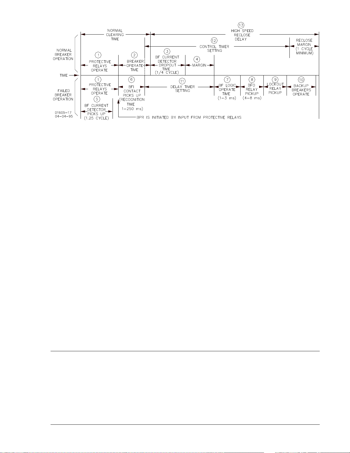
Figure 1-1. Breaker Failure Timing Diagram
Because timing is such an important part of breaker failure protection, the BE1-BPR relay provides timing
diagnostics to assist in determining if the timer settings are optimal and to allow other aspects of the
protection system to be checked. This timing diagnostic is a Timer Log or TLOG. An example of its use is
to create a log of the margin remaining between when a fault is cleared and when a breaker failure would
occur. After a normal breaker operation clears a fault, the time remaining from when the BE1-BPR
overcurrent fault detector drops out and the breaker failure delay timer would have timed out is the
MARGIN. This time can be recorded by saving the time left on the delay timer when the fault detector
drops out by using the program timer log alarm (PTLOG) command. The time logged will correspond to
the MARGIN value in Figure 1-1. If there is a discrepancy between the calculated and actual margin value
stored in the TLOG, corrective action can be taken to correct the protection timing before a serious
problem occurs. If the MARGIN is too small or too large, the delay timer setting can be adjusted for
optimal operation. The PTLOG command also allows an alarm time to be programmed so that if the
MARGIN drops below a pre-determined value, the Alarm output (ALM) can be automatically closed to
signal the operator that immediate attention is required. Timing diagnostics can be programmed for each
of the six timers available.
Breaker Arc Detector
An important breaker diagnostic feature is the detection of low level arcing across an open breaker
(flashover). Flashover might occur because lightning struck and a surge suppressor failed or air pressure
in an air blast circuit breaker is lost. If left undetected, severe damage to the breaker contacts could
result. BE1-BPR relays can detect this type of fault using an extra low level phase overcurrent pickup and
a long moving average filter. These features have been provided as standard features in the BE1-BPR
relays. Used with the programmable logic, a breaker arc detector can be programmed to provide a
breaker close output to close the breaker and extinguish the arc. Additional interlocks may be added to
the logic to inhibit the breaker close signal if the breaker is isolating a faulted line.
IRIG Standard Time Format
The IRIG function allows the BE1-BPR relay to synchronize the on-board real time clock with a standard
IRIG demodulated time signal. Synchronization is automatic and the BE1-BPR initiates synchronization at
regular intervals (approximately 20 seconds) in order to maintain the one millisecond overall accuracy.
APPLICATION - ENHANCED MODELS
Enhanced BE1-BPR models have all of the features of standard models plus the additional features
described in the following paragraphs.
Breaker Contact Maintenance and Resistor Protection
Enhanced model BE1-BPR relays can perform two protection diagnostic functions other than the breaker
failure function. One, they can estimate breaker contact duty (wear) and signal when preventative
maintenance is needed. Two, they can estimate breaker opening resistor heating and provide a block
reclose signal to protect the breaker resistor when the resistor heating could exceed the maximum
resistor rating.
9272000990 Rev J BE1-BPR General Information 1-3
Page 16

Fault Recording
Enhanced model BE1-BPR relays can also be configured to record and save digital fault data for all three
phases plus neutral (0 to 200 amperes) and the digital state of each input and output contact. Analog
waveforms are digitized by sampling the waveforms at a periodic rate and converting the measured
signals to digital values. When a fault occurs, the digital data is stored as a fault record. Multiple fault
records can be stored and recalled through the serial port by an operator. To display the fault waveform
for analysis, recalled data can be imported into a data base file and converted into a graph. Standard
programs that read and display ASCII data (in accordance with IEEE Standard Common Format for
Transient Data Exchange (COMTRADE) for Power Systems) can also be used. BESTView application
software provides a simple terminal interface to communicate with the relay, retrieve and display
COMTRADE oscillographic fault data, and provide a remote front panel interface. This software is not
required to communicate with the relay. However, it combines the functions of a number of separate
packages into one program that is optimized for the BE1-BPR relay. To order this software free of charge,
contact the Customer Service Department of the Power Systems Group, Basler Electric, and request the
BESTView Software Package.
MODEL NUMBERS
Tables 1-1 and 1-2 provide information for the nominal current input to the current transformers, part
number, options, mounting style, and operating power supply voltage. Standard BE1-BPR relays do not
have oscillography, fault records, contact duty logs, or two calibration levels (current metering is limited to
10 amperes).
Table 1-1. BE1-BPR Relays, 5 Aac CT Secondary
Part Number Options Mounting Style IRIG Power Supply
9272000300 Standard 19” Rack Mount Yes 48/125 Vac/Vdc
9272000301 Standard 19” Rack Mount Yes 125/250 Vac/Vdc
9272000302 Enhanced 19” Rack Mount Yes 48/125 Vac/Vdc
9272000303 Enhanced 19” Rack Mount Yes 125/250 Vac/Vdc
9272000309 Standard Vertical Mount Yes 48/125 Vac/Vdc
9272000310 Standard Vertical Mount Yes 125/250 Vac/Vdc
9272000311 Enhanced Vertical Mount Yes 48/125 Vac/Vdc
9272000312 Enhanced Vertical Mount Yes 125/250 Vac/Vdc
9272000328 Enhanced Vertical Mount Yes 48/125 Vac/Vdc
9272000329 Enhanced 19” Rack Mount Yes 48/125 Vac/Vdc
9272000330 Enhanced Vertical Mount Yes 125/250 Vac/Vdc
9272000331 Enhanced 19” Rack Mount Yes 125/250 Vac/Vdc
Table 1-2. BE1-BPR Relays, 1 Aac CT Secondary
Part Number Options Mounting Style IRIG Power Supply
9272000304 Standard 19” Rack Mount Yes 48/125 Vac/Vdc
9272000305 Standard 19” Rack Mount Yes 125/250 Vac/Vdc
9272000306 Enhanced 19” Rack Mount Yes 48/125 Vac/Vdc
9272000307 Enhanced 19” Rack Mount Yes 125/250 Vac/Vdc
SPECIFICATIONS
BE1-BPR Breaker Protection Relays have the following features and capabilities.
1-4 BE1-BPR General Information 9272000990 Rev J
Page 17

Current Sensing
Four isolated inputs with a maximum burden of less than 0.1 ohm.
5 Ampere CT: Maximum continuous current: 20 Aac
Maximum one second current: 500 Aac
1 Ampere CT: Maximum continuous current: 4 Aac
Maximum one second current: 80 Aac
Current Detector Pickup Time
Instantaneous Fault Detector (50/60 Hz RMS Filter Type 1 and 3)
1 ¼ cycle maximum for current 125% greater than pickup.
Moving Average Window Fault Detector (50/60 Hz RMS Filter Type 2)
Maximum pickup time is (Window_size/C_PM + 1 ¼ (cy)), where Window_size = Filter window size in
cycles (Range 1 - 100) and C_PM = Current Pickup Multiple
Current Detector Dropout Time
Instantaneous Fault Detector (50/60 Hz RMS Filter Type 1 and 3)
Dropout/pickup ratio: 90%, typical. One-quarter cycle (4.2 milliseconds @ 60 hertz) from the time the
current falls below and stays below 25% of the RMS level or 1 ¼ cycle from the time the RMS current
signal decreases to less than 75% of pickup.
Moving Average Window Fault Detector (50/60 Hz RMS Filter Type 2)
Maximum dropout time is (Window_size-(Window_size/C_PM) + 1 ¼ (cy)), where Window_size = Filter
window size in cycles (Range 1 - 100) and C_PM = Current Pickup Multiple level before dropout.
Current Pickup Range
Three independent settings, selectable as three-phase or neutral.
Instantaneous Fault Detector (50/60 Hz RMS Filter Type 1 and 3)
5 ampere CT: 0.25 to 9.99 amperes selectable in 0.01 increments
1 ampere CT: 0.05 to 2.00 amperes selectable in 0.01 increments
Moving Average Window Fault Detector (50/60 Hz RMS Filter Type 2)
5 ampere CT: 0.05 to 1.00 amperes selectable in 0.01 increments
1 ampere CT: 0.01 to 0.20 amperes selectable in 0.01 increments
Current Pickup Accuracy
Instantaneous Fault Detector (50/60 Hz RMS Filter Type 1 and 3)
5 ampere CT: ±2% of pickup setting or ±0.05 Aac (whichever is greater)
1 ampere CT: ±2% of pickup setting or ±0.01 Aac (whichever is greater)
Moving Average Window Fault Detector (50/60 Hz RMS Filter Type 2):
5 ampere CT: ±25% with window of 10 cycles or larger
1 ampere CT: ±25% with window of 10 cycles or larger
Sample Rate
12 samples per cycle (720 samples per second at 60 hertz, 600 samples per second at 50 hertz).
Oscillograph Recording Range
5 ampere CT: 0 - 200 amperes, rms
1 ampere CT: 0 - 40 amperes, rms
Oscillograph Data Accuracy
±0.2% of full scale or 5% of reading, whichever is greater
9272000990 Rev J BE1-BPR General Information 1-5
Page 18

Oscillograph Recording Format
IEEE C37.111-1991, IEEE Standard Common Format for Transient Data Exchange (COMTRADE) for
Power Systems.
Contact Sensing Input Recognition Time
User programmable 4 - 255 milliseconds ±0.01% of setting to closest sample time (one-twelfth cycle = 1.4
milliseconds at 60 hertz or 1.7 milliseconds at 50 hertz).
Contact Sensing Input Range
Energizing levels for contact sensing inputs are jumper selectable. Table 1-3 lists the turn-on range for
each control voltage range and jumper position. Refer to Section 7, Installation, Contact Sensing Inputs,
for jumper location.
Table 1-3. Contact Sensing Turn-On Voltage
Turn-On Range
Nominal Control Voltage
48/125 Vac/Vdc 26 V to 38 V 69 V to 100 V
125/250 Vac/Vdc 69 V to 100 V 138 V to 200 V
(JP200 through JP206)
Pin 1 - Pin 2 Pin 2 - Pin 3
Contact Sensing Input Burden
Burden per contact for sensing depends on the power supply model and the input voltage. The input
sensing range is the same as the dc power supply range. Table 1-4 provides appropriate burden
specifications.
Table 1-4. Contact Sensing Burden
Turn-On Range
Nominal Control Voltage
48/125 Vac/Vdc
125/250 Vac/Vdc
IRIG Input
Signal: The IRIG input accepts a demodulated (dc level-shifted) signal.
Maximum input signal level is 25 volts.
Burden: Burden is nonlinear and rated at 4 kΩ at 5 Vdc.
Timers
Standard (TD[n]): Six microprocessor controlled timers. Programmable in milliseconds,
seconds, or cycles. Ranges and increments are: 10 to 999 milliseconds
in 1 millisecond increments; 1 to 60 seconds in 0.1 second increments;
or 1 to 3,600 cycles in 1 cycle increments. A setting of 0 will disable the
timer. If programmed in cycles, the BE1-BPR relay will display the
equivalent time in milliseconds.
Reclosing (TD79[n]): Six microprocessor controlled timers. Programmable in milliseconds,
seconds, or cycles. Ranges and increments are: 10 to 999 milliseconds
in 1 millisecond increments; 1 to 99 seconds in 0.1 second increments;
100 to 600 seconds in 1 second increments; or 1 to 9,999 in 1 cycle
increments.
(JP200 through JP206)
Pin 1 - Pin 2 Pin 2 - Pin 3
16 kΩ 28 kΩ
56 kΩ 92 kΩ
1-6 BE1-BPR General Information 9272000990 Rev J
Page 19

Timer Accuracy
Standard (TD[n]): +4 and -1 milliseconds ±0.01% of setting
Reclosing (TD79[n]): +20 and -1 milliseconds ±0.01% of setting
Real Time Clock Set Ability
±1 second
Real Time Clock Resolution
±1 second
Real Time Clock Stability
±30 ppm typical
Real Time Clock Accuracy
Relays with IRIG, ±1 millisecond. If IRIG signal is lost, accuracy defaults to the real time clock stability.
BESTlogic Operate Time
Operate time is 1.4 milliseconds typical, 2.8 milliseconds maximum at 60 hertz.
Output Relays
Any output contact closed by the relay logic will be held closed for 200 to 250 milliseconds even if the
initial cause of the closing goes away. After 200 to 250 milliseconds, the relay close time is determined by
the state of the relay logic. This minimum hold time may be disabled by using the PHOLD command.
Factory Presets
ALARM Output: Output contacts close when ALARM logic (LOA) is true or power is lost.
Outputs 1 - 5: Output contacts close when the corresponding logic equation (LO1 -
LO5) is true.
Pickup Time (All models except 9272000328, 9272000329, 9272000330, and 9272000331)
ALARM: 8 milliseconds typical, 10 milliseconds maximum
OUTPUT 1: 4 milliseconds typical, 5 milliseconds maximum
OUTPUT 2, 3, 4, 5: 8 milliseconds typical, 10 milliseconds maximum
Pickup Time (Models 9272000328, 9272000329, 9272000330, and 9272000331 only)
ALARM: 8 milliseconds typical, 10 milliseconds maximum
OUTPUT 1, 2: 4 milliseconds typical, 5 milliseconds maximum
OUTPUT 3, 4, 5: 8 milliseconds typical, 10 milliseconds maximum
Resistive Ratings
120 Vac: Make, break, and carry 7 Aac continuously
250 Vdc: Make and carry 30 Adc for 0.2 s, carry 7 Adc continuously,
break 0.3 Adc
500 Vdc: Make and carry 15 Adc for 0.2 s, carry 7 Adc continuously,
break 0.3 Adc
Inductive Ratings
120 Vac, 125/250 Vdc: Break 0.3 A (L/R = 0.04)
Display
Two-line, 16 character alphanumeric LCD (liquid crystal display) with LED (light emitting diode) backlight.
Operating Temperature: -40°C to +70°C (-40°F to +158°F)
Display contrast may be impaired at temperatures below -20°C (-4°F).
9272000990 Rev J BE1-BPR General Information 1-7
Page 20

Targets/Indicators
Five diagnostic LED indicators are provided.
POWER: Green LED (normally ON) to indicate power supply is operating.
CLOCK: Green LED (normally OFF) turns ON to indicate that the clock needs to
be set.
50PU: Red LED (normally OFF) turns ON to indicate one or more of the inputs
has exceeded the pickup level(s).
ALARM: Red LED (normally OFF) turns ON to indicate problems. Output A
(ALARM) de-energizes (closes) when ALARM LED is ON.
TARGET: Red LED (normally OFF) turns ON if one or more of the relay outputs
has been energized. (If programmed by the PTARGET command.)
Keypad
Five keys are used to access information on the display and enter settings.
Communications
Only one communication port can be active at any time.
Front panel connector: RS-232, 9-pin, female, D-sub DCE
Rear panel connectors: RS-232, 9-pin, female, D-sub DCE
RS-485, 3-position terminal block
Baud Rate: 300, 600, 1200, 2400, 4800, 9600, and 19200
Buffer Size: 40 characters
Protocol: ASCII and binary data transmissions
Power Supply
Power for the internal circuitry may be derived from ac or dc external power sources. Power supply data
is provided in Table 1-5.
Table 1-5. Power Supply Specifications
Power Supply
Range
48/125 V 48 Vdc
125/250 V 125 Vdc
Isolation
All output and power supply terminals have MOV suppressors. Maximum applied voltage must be no
greater than 300 volts where MOV suppressors are used. Surge suppression capacitors are installed
between terminal pairs and between terminals and chassis ground. When testing with 1,500 Vac, leakage
current (approximately 8 milliamperes per terminal) is expected. 1.500 Vac (RMS) at 45 to 65 hertz for
one minute or 2,121 Vdc may be applied between circuit groups, and between circuit group and chassis
ground in accordance with IEC 255-5 and ANSI/IEEE C37.90-1989 (Dielectric Tests).
Nominal Input
Voltage
125 Vdc
120 Vac
120 Vac
250 Vdc
240 Vac
Input Voltage
Range
40 to 60 Vdc
90 to 150 Vdc
100 to 130 Vac
90 to 150 Vdc
100 to 130 Vac
180 to 300 Vdc
200 to 260 Vac
Burden at Nominal
(Maximum)
8 W (10 W)
8 W (10 W)
8 W (10 W)
8 W (10 W)
8 W (10 W)
8 W (10 W)
8 W (10 W)
Surge Withstand Capability
Qualified to ANSI/IEEE C37.90.1-1989, Standard Surge Withstand Capability (SWC) Tests for Protective
Relays and Relay Systems. Note: This qualification does not include the front RS-232 communication
port.
1-8 BE1-BPR General Information 9272000990 Rev J
Page 21

Radio Frequency Interference (RFI)
Field tested using a 5 W, hand-held transceiver operating at random frequencies centered around 144
MHz and 440 MHz, with the antenna located six inches from the relay in both horizontal and vertical
planes.
Temperature
Operating: -40°C to +70°C (-40°F to +158°F)
Storage: -40°C to +70°C (-40°F to +158°F)
Shock
Type tested to withstand 15 G in each of three mutually perpendicular planes, swept over the range of 10
to 500 Hz for a total of 6 sweeps; 15 minutes each sweep, without structural damage or degradation of
performance.
Vibration
Type tested to withstand 2 G in each of three mutually perpendicular planes, swept over the range of 10
to 500 Hz for a total of 6 sweeps; 15 minutes each sweep, without structural damage or degradation of
performance.
Gost-R Certification
Gost-R certified, No. POCC US.ME05.B03391; complies with the relevant standards of Gosstandart of
Russia. Issued by accredited certification body POCC RU.0001.11ME05.
Weight
12 lb (5.44 kg) maximum
9272000990 Rev J BE1-BPR General Information 1-9
Page 22

This page intentionally left blank.
1-10 BE1-BPR General Information 9272000990 Rev J
Page 23

SECTION 2 • APPLICATION
TABLE OF CONTENTS
SECTION 2 • APPLICATION .................................................................................................................... 2-1
GENERAL .............................................................................................................................................. 2-1
APPLICATION DATA ............................................................................................................................. 2-1
Contact Sensing Inputs ...................................................................................................................... 2-1
Fault Detectors ................................................................................................................................... 2-1
General Purpose Timers .................................................................................................................... 2-5
Reclosing Timers ................................................................................................................................ 2-6
Output Contacts ................................................................................................................................. 2-7
Trip Circuit Monitor Logic ................................................................................................................... 2-7
Breaker Arc Detector .......................................................................................................................... 2-9
Breaker Resistor Protection ............................................................................................................. 2-10
Breaker Failure Protection with Pre-Insertion Resistors .................................................................. 2-11
Breaker Contact Duty Log ................................................................................................................ 2-11
Reclosing Functions ......................................................................................................................... 2-12
PREPROGRAMMED LOGIC DESCRIPTION ..................................................................................... 2-12
Breaker Failure Logic 1 for Standard Relays (BFL1) ....................................................................... 2-12
Breaker Failure Logic 2 for Standard Relays (BFL2) ....................................................................... 2-13
Breaker Failure Logic 3 for Standard Relays (BFL3) ....................................................................... 2-14
Breaker Failure Logic 1 for Enhanced Relays (BFL1E) ................................................................... 2-15
Breaker Failure Logic 2 for Enhanced Relays (BFL2E) ................................................................... 2-17
Breaker Failure Logic 3 for Enhanced Relays (BFL3E) ................................................................... 2-18
Figures
Figure 2-1. Maximum Instantaneous Pickup Timing ................................................................................. 2-2
Figure 2-2. Maximum Instantaneous Dropout Timing ............................................................................... 2-3
Figure 2-3. Maximum Pickup Timing with 10 Cycle MAF FD .................................................................... 2-3
Figure 2-4. Maximum Dropout Timing with 10 Cycle MAF Fault Detector
Figure 2-5. Multiple Breaker Arrangement ................................................................................................ 2-5
Figure 2-6. Delay Timer Operation ............................................................................................................ 2-5
Figure 2-7. Control Timer Operation .......................................................................................................... 2-6
Figure 2-8. Trip Circuit Monitor Schematic Diagram ................................................................................. 2-8
Figure 2-9. Trip Circuit Monitor Logic Diagram ......................................................................................... 2-8
Figure 2-10. Trip Circuit Monitor Timing Diagram ..................................................................................... 2-8
Figure 2-11. Trip Circuit Monitor with BFI Sensing .................................................................................... 2-9
Figure 2-12. Breaker Arc Detector Circuits ............................................................................................. 2-10
Figure 2-13. Breaker Resistor Protection Circuits ................................................................................... 2-10
Figure 2-14. Breaker Contact Duty Log Circuits ...................................................................................... 2-11
Figure 2-15. Reclosing Logic Circuit ........................................................................................................ 2-12
................................................ 2-4
9272000990 Rev J BE1-BPR Application i
Page 24

This page intentionally left blank.
ii BE1-BPR Application 9272000990 Rev J
Page 25

SECTION 2 • APPLICATION
GENERAL
BE1-BPR relays have seven inputs and five outputs plus an alarm output. There are three general
purpose overcurrent fault detectors, six multipurpose timers, a three-shot recloser, and special outputs
that are internally generated by the microprocessor. Using simple Boolean expressions, the user can
logically connect the various functional blocks to create a custom, application specific, logic scheme to
handle special protection requirements.
Standard model relays have the following special features:
• Three shot recloser.
• Pre-insertion breaker resistor operations counter with programmable reset and block reclose signal.
• Six configurable timing diagnostic logs each with an optional alarm setting. This feature can be used
to monitor the various protection system parameters such as the margin between normal breaker
operation and breaker fail.
Enhanced model relays have the standard model features plus these special features:
• Twelve entry fault log detailing the system and relay status at the time the fault trigger occurred
• Twelve entry COMTRADE fault record consisting of configuration (CFG) and data (DAT) files. The
COMTRADE data contains 4 cycles of pre-fault and 16 cycles of post-fault data sampled at 12
samples per cycle. Each sample consists of the analog-to-digital converter values for each current
channel as well as 32 digital channels (a digital channel is for the digital status of an input, output, or
alarm).
2
• Integrated I
t breaker contact duty monitor with alarm.
A minimum of three basic breaker failure schemes are pre-programmed into nonvolatile memory. These
schemes take full advantage of the special features available in this relay without requiring the user to do
any programming. The user only selects the scheme desired and enters the pickup and timer settings.
APPLICATION DATA
Contact Sensing Inputs
Each BE1-BPR relay provides seven opto-isolated contact sensing inputs. Three inputs (IN1-3) are each
completely isolated. Inputs 4 and 5 (IN4, IN5) share one common terminal and inputs 6 and 7 (IN6, IN7)
share another common terminal. Each input has programmable recognition and debounce (time allowed
for the external contacts to stabilize) times. Typically the default setting of four milliseconds recognition
and twelve millisecond debounce should be used unless extremely slow or irregular contacts are applied.
The default setting assures that the signal be present on at least two consecutive scans of the input
status before recognition can occur.
It is recommended that for protective functions, a positive TRUE logic be used to enable protective
outputs. This prevents a broken wire or loose connection from causing a protective trip. For example, a
52b input would be preferred for protection logic that is enabled when the breaker opens (i.e. block
reclose or breaker arcing/flash over) and a 52a input would be preferred for protection logic that should
be enabled when the breaker closes. On the other hand, for a diagnostic alarm, a negative TRUE logic
may be preferred since it will give an alarm if the checked diagnostic occurs and also give an alarm
(depending on the logic) for a bad or broken connection.
Fault Detectors
BPR relays provide three independent fault detectors. Each fault detector can be programmed for phase
or neutral input sensing. Also, each fault detector can be setup to operate as an instantaneous (50) or
moving average filter (MAF) fault detector.
Instantaneous (50) Fault Detector Type 1
An instantaneous fault detector provides a typical one cycle pickup and one-quarter cycle dropout for high
speed operation. A three cycle software delay is imposed on any Type 1 fault detector when the current
9272000990 Rev J BE1-BPR Application 2-1
Page 26
level is less than 40 milliamperes above the pickup setting. This prevents noise induced trips from
4
6
8
10
12
14
16
18
20
22
1.05 1.25 2 5 20 40
MULTIPLES OF PICKUP
MAX. PICKUP TIME (ms)
PU=5.00A
PU=0.25A
PU=9.99A
D2838-21
occurring. The Type 1 is used in BF logic schemes and is programmed by setting the fault detector logic
(LF) type to PI (phase overcurrent) or NI (neutral overcurrent) and the digital filter selection to 1.
For the fault detector to pickup, the RMS value of the last cycle of current must be above the pickup
setting. Due to the analog input circuitry design, the RMS value is clamped (limited) at approximately 13
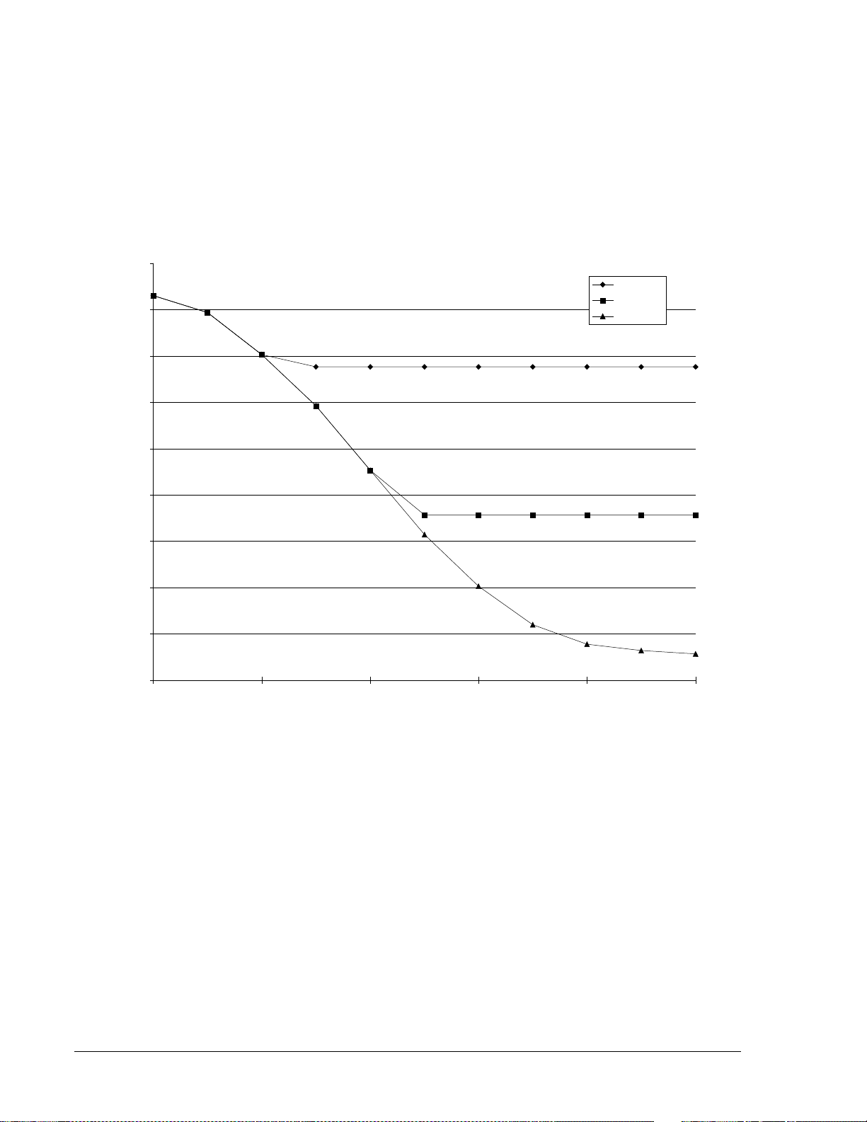
amperes. As the multiple of pickup level increases, the pickup time decreases. Because of the limiting
above 13 amperes, the pickup time does not appreciably decrease at high multiples of pickup. Also, the
pickup may be delayed up to one-quarter cycle because the RMS current is calculated every quarter
cycle. However, in no case will the pickup be slower than one and one-quarter cycles.
Figure 2-1 shows maximum pickup timing versus current input levels.
Figure 2-1. Maximum Instantaneous Pickup Timing
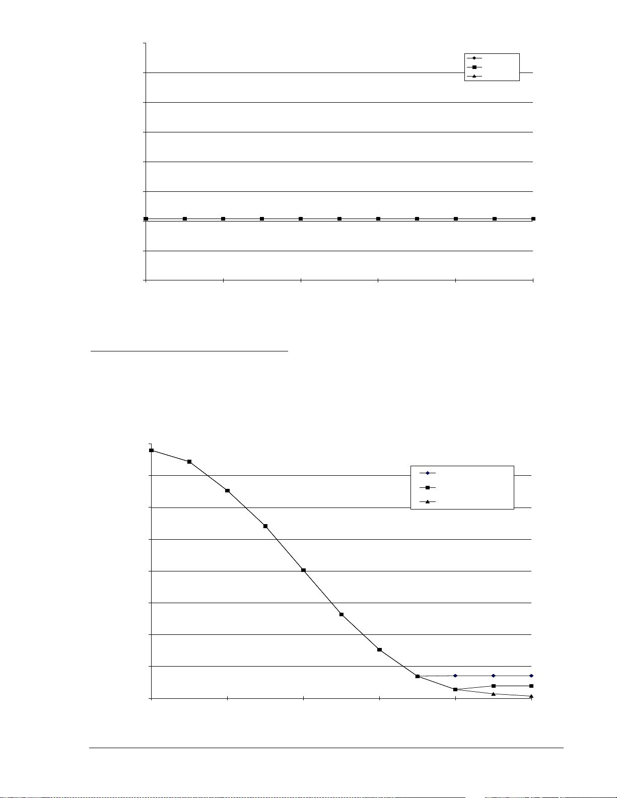
For the Type 1 fault detector to dropout, one of two conditions must occur. One, three sequential analogto-digital (A/D) samples must be less than one-fourth of the RMS current level for the last quarter-cycle
calculation. Two, the RMS current signal level must decrease to less than 75% of pickup. Samples are
made twelve times per line cycle and RMS current is calculated four times per line cycle. Three samples
are used to compensate for zero crossings and noise. A short dropout delay is advantageous for BF logic
in order to allow for the minimum timing margin in critical applications.
Figure 2-2 shows maximum dropout timing versus current input levels.
2-2 BE1-BPR Application 9272000990 Rev J
Page 27
0
2
4
6
8
10
12
14
16
1.05 1.25 2 5 20 40
MULTIPLES OF PICKUP BEFORE DROP OUT
MAX. DROPOUT TIME (ms)
PU=9.99A
PU=5.00A
PU=0.25A
PU=9.99A
PU=5.00A
PU=0.25A
D2838-22
20
40
60
80
100
120
140
160
180
1.05 1.25 2 5 20 40
MULTIPLES OF
PICKUP
MAX. PICKUP TIME (ms)
PU=1.00A, 10 CYC
PU=0.50A, 10 CYC
PU=0.05A, 10 CYC
PU=1.00A, 10 CYC
PU=0.50A, 10 CYC
PU=0.05A, 10 CYC
D2838-23
Figure 2-2. Maximum Instantaneous Dropout Timing
Moving Average Filter Fault Detector Type 2
A moving average filter (MAF) fault detector provides for a slower but more consistent pickup at low
current levels. A MAF fault detector should be used in applications where the current to be detected is
less than 0.25 ampere. Typically, the response time for pickup and dropout depends on the number of
cycles averaged and how high the input current is above pickup.
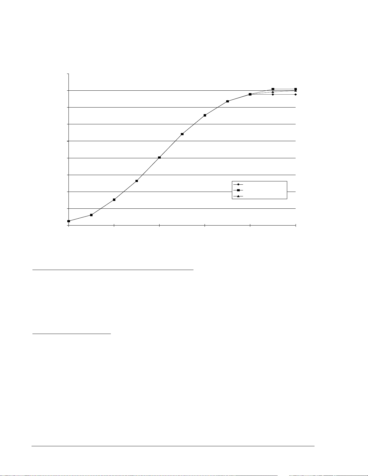
Figure 2-3 shows maximum pickup timing versus current input levels for a 10 cycle MAF fault detector.
Figure 2-3. Maximum Pickup Timing with 10 Cycle MAF FD
9272000990 Rev J BE1-BPR Application 2-3
Page 28
This MAF fault detector is programmed by setting the fault detector digital filter selection to 2 (DFLTR2).
20
40
60
80
100
120
140
160
180
200
1.05 1.25 2 5 20 40
MULTIPLES OF PICKUP BEFORE DR OPOUT
MAX. DROPOUT TIME (ms)
PU=1.00A, 10 CYC
PU=0.50A, 10 CYC
PU=0.05A, 10 CYC
PU=1.00A, 10 CYC
PU=0.50A, 10 CYC
PU=0.05A, 10 CYC
D2838-24
For the MAF fault detector to pickup (or dropout), the rms value of the average of the last 'n' cycles of
current must be above (or below) the pickup setting. Typically, this filter is slow to pickup and slow to
dropout but it is intended for use in low current applications where speed is not critical.
Figure 2-4 shows maximum dropout timing versus current input levels for a 10 cycle MAF fault detector.
Figure 2-4. Maximum Dropout Timing with 10 Cycle MAF Fault Detector
Three-Phase Fault Instantaneous (50) Fault Detector Type 3
This fault detector has the same characteristics as the Type 1 instantaneous fault detector with the
exception that all three phases must be picked up before the fault detector will pickup. This fault detector
can be used in BF logic schemes and is programmed by setting the fault detector logic (LF) type to PI
(phase overcurrent) and the digital filter selection to 3.
A 3-phase fault is the worst case fault for system stability and requires fast clearing times with small
margins. A 3-phase fault detector and a separate timer could be used in addition to the 3-phase fault
detector and timer to allow BF protection for both worst case faults and normal faults.
Application of Fault Detectors
Phase and Ground Instantaneous Fault Detectors. Normally, it is adequate to monitor the three phase
currents as they represent the current in the poles of the protected breaker. However, if the sensitivity of
the ground relays is significantly higher than the sensitivity of the phase relays, it may be desirable to
apply a ground fault detector so that you can be assured that the breaker failure protection will pickup for
any fault that is sensed by the initiating relays. Each fault detector can be independently set to monitor
either the three phase current inputs or the neutral current input. Fault detector F1 is programmed as a
phase instantaneous fault detector and fault detector F2 is programmed as a neutral instantaneous fault
detector in all of the preprogrammed logic schemes.
Three-Phase Instantaneous Fault Detectors. For system stability, a three-phase fault is the worst case.
The dynamic stability of the system is not affected as much by the other fault combinations. Since threephase faults are generally rarer than the other fault combinations, it may be desirable to enhance security
by treating three-phase faults differently. One of the fault detectors can be set up as a PI, 3 (phase
current, Type 3) fault detector to supervise a timer set at the three phase fault, dynamic stability limit. The
normal timer supervised by the other fault detectors would then be set with a longer time delay (with more
margin) set at the two phase and ground fault (the next worst case), dynamic stability limit.
2-4 BE1-BPR Application 9272000990 Rev J
Page 29
Low Level Current Detector. If the breaker fails while being opened for normal load switching or due to re-
INITIATE
OUTPUT
RESET
TD[n]
D2635-11
strike after the line has been isolated, the currents flowing across the failed interrupter may be too low to
reliably detect by conventional means. The Type 2 fault detector’s moving average filter allows the BE1BPR to discern the low level line charging current from random noise. The application of this fault detector
is described in detail in the Breaker Arc Detector sub-section. Fault detector F3 is programmed as a
phase MAF fault detector in all pre-programmed logic schemes.
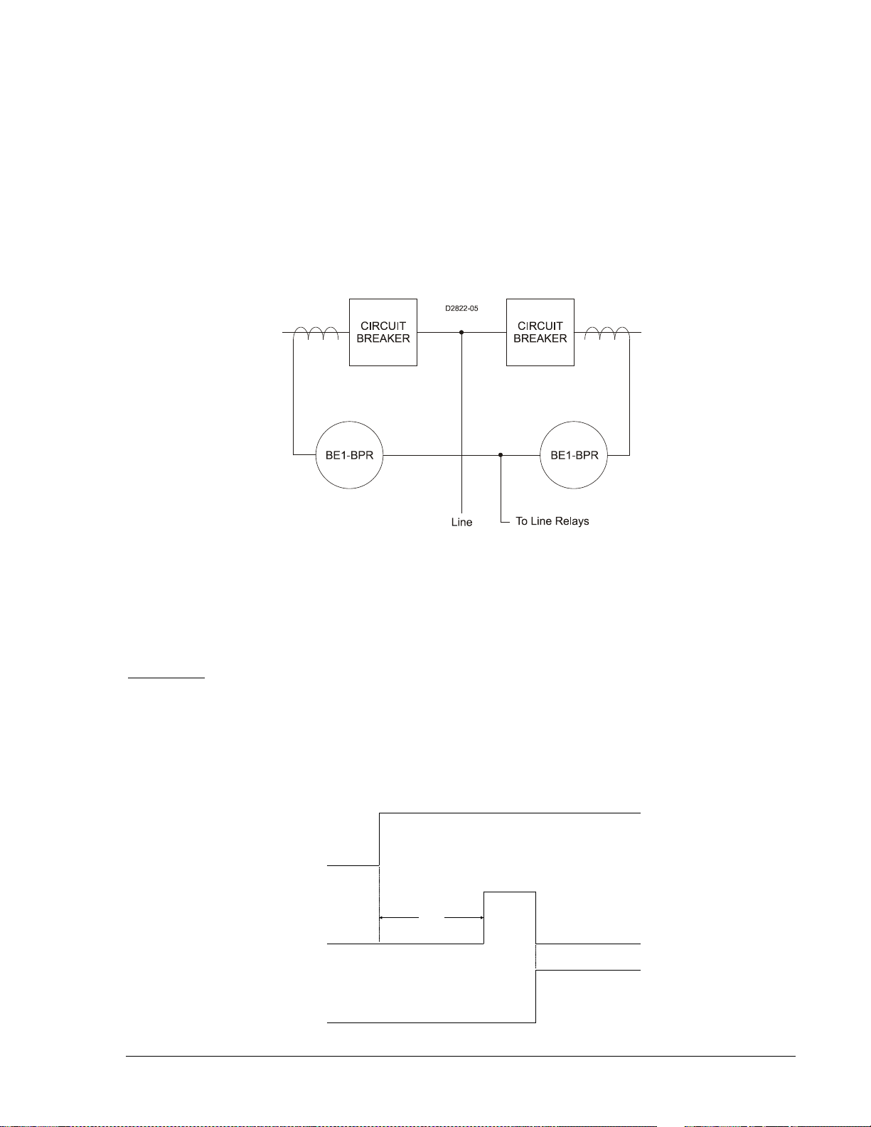
Multiple Breaker Arrangements. In ring bus and breaker and half bus applications, CTs from two breakers
are often connected in parallel. If the BE1-BPR is connected to these CTs as shown in Figure 2-5, low
fault detector pickup settings should be used with caution. In this arrangement, the CT feeding the BE1BPR can be energized on the secondary side from the CT on the adjacent circuit breaker. This results in
current flowing in the BE1-BPR even when the protected circuit breaker has successfully interrupted the
fault. This secondary excitation current is generally negligible except when flux remnants or high
current/burden causes the CT to saturate.
Figure 2-5. Multiple Breaker Arrangement
General Purpose Timers
Each BPR relay provides six independent timers for breaker failure timing and diagnostics. Each timer
can be programmed as a delay or a control timer and can have independent START and RESET
conditions. Each timer can also provide a diagnostic log and/or alarm. These features are explained in the
following paragraphs.
Delay Timer
A Delay timer has two inputs START and RESET, and one output T[n]. The timer will not start until the
start condition becomes TRUE and the RESET input is FALSE. Once the timer is started, a preprogrammed time delay, TD[n], is loaded and the timer starts timing out. Toggling of the START input has
no effect once the timer is started. The timer times out TD[n] time after the timer is started unless the
timer is RESET before the time expires. If the timer times out, then the T[n] output becomes TRUE. After
timeout, T[n] remains TRUE until the timer is RESET. Delay timer operation is illustrated in
Figure 2-6.
Figure 2-6. Delay Timer Operation
9272000990 Rev J BE1-BPR Application 2-5
Page 30

This type of timer is used to delay an operation in order to allow time for other processes to occur. For
INITIATE
OUTPUT TD[n]
RESET
D2635-12
example, in breaker failure applications, a delay timer is user to delay the breaker failure output until the
primary protection scheme has sufficient time to operate the breaker and open the circuit.
Control Timer
A Control timer has two inputs START and RESET, and one output T[n]. The timer will not start until the
start condition becomes TRUE and the RESET input is FALSE. Once the timer is started, a preprogrammed time delay, TD[n], is loaded and the timer starts timing out. The timer times out TD[n] time
after the timer is started unless the timer is RESET before the time expires. During the entire period the
timer is ON (i.e. not timed out and not reset), the output T[n] is TRUE. If the timer times out, then the T[n]
output becomes FALSE. After timeout, the T[n] remains FALSE until the timer is RESET and a new
START input is received. Control timer operation is illustrated in
Figure 2-7.
Figure 2-7. Control Timer Operation
This type of timer is used to provide a limited window of time for an operation to occur or to provide a
feedback signal to latch-in an input for a predetermined time. For example, in breaker failure applications,
a control timer can be used to latch-in a BFI input to ensure that once a BFI occurs a premature opening
of the BFI for whatever reason does not disable the BF logic.
Another application is to prevent a BF operation due to stuck contacts on the BFI input. BFI input stuck
contacts would cause a false trip any time the fault detector picks up. This problem can be minimized by
using a control timer to limit the window of opportunity for which the input can cause a trip output.
Timer Diagnostics
In many applications it is desirable to have a record of the timing relationship between different events. In
order to acquire this record, data must be available and accumulated over a period of time. A method to
obtain and collect this data has been incorporated into the BE1-BPR relays. This method allows relative
or absolute timing between any input, output or internal operation (i.e. timers, fault detectors) to be logged
into a circular 40 event record. The data can be retrieved for analysis using the TLOG[n] command. In
addition, because some timing requirements are critical to proper system operation, an optional alarm
output can be automatically triggered if the time logged is outside a predetermined level. The logic used
to save a timer value to the log and the optional alarm time is programmable using the PTLOG[n]
command.
Refer to Section 1, General Information, Timing Diagnostics, for detailed information on BF timing and an
example of using the timing diagnostics to create a MARGIN log.
Reclosing Timers
Each BE1-BPR relay provides six independent reclosing timers. Three reclosing timers (TD791, TD792,
and TD793) provide time delays for the multiple shots (one, two, and three). TD79R is the reset time
delay, TD79F is the reclose fail time delay, and TD79M is the maximum cycle timer.
Reclosing timer delay settings are programmable from the front panel or the serial port using the TD79
command. The three reclosing time delays can be set at zero or from 10 to 999 milliseconds in 1
millisecond increments, 1 to 99 seconds in 0.1 second increments, or 100 to 600 seconds in 1 second
2-6 BE1-BPR Application 9272000990 Rev J
Page 31

increments. Each of the reclosing timers may be disabled by a setting of zero. When a reclosing timer set
at zero is reached in the reclosing sequence, the reclosing sequence is interrupted and the relay will enter
lockout.
Reset timer (TD79R) begins timing out when the RESET logic becomes TRUE (breaker closes). The
reset timer is reset when the breaker trips. If the reset timer times out while the breaker is closed, the
recloser goes to RESET.
If enabled, the reclose fail timer (TD79F) starts whenever a reclose output is given and stops when the
RESET logic indicates the breaker has closed. If the reclose fail timer times out before the RESET logic
becomes TRUE, the recloser sets the reclose fail diagnostic flag. The reclose fail diagnostic flag can be
inhibited by setting the time delay to zero. The reclose fail function can be inhibited by setting the
reclosing mode (TYPE) in the LR command to zero (0).
If the total reclosing time between reset states exceeds the maximum reclose cycle timer (TD79M) setting
(excluding time while in the WAIT state), the recloser goes to the lockout state. The maximum reclose
cycle timer can be inhibited by setting the time delay to zero.
Output Contacts
Each BE1-BPR relay has five isolated normally open (NO) output contacts (OUT1-OUT5) plus one
isolated normally closed (NC) alarm output (ALM). Output contact OUT1 is a high speed contact with a
maximum operating time of ¼ cycle. By using the PTARGET command, output relays can be
programmed to latch target data into memory.
Output contacts OUT1 through OUT5 are controlled by the status of the internal logic of signals O1
through O5. If O[n] becomes TRUE, then the corresponding output relay is energized and closes the
normally open contacts. If the PHOLD feature is enabled, the output contacts are held in an energized
state for 200 to 250 milliseconds when O[n] becomes TRUE. Each output contact then resumes following
the internal logic. The PHOLD function ensures that the TRIP output doesn’t interrupt the trip coil current
but allows the trip coil current to be interrupted by the 52A contact. Section 4, Functional Description,
provides more information about the PHOLD command.
All output contacts are factory set to NO. However, OUT1 - OUT4 may be changed to NC by changing a
soldered jumper next to the output relays on the printed circuit board. NO contacts are typically used in
trip circuits and using this type of contact allows the relay electronics to be drawn out without activating
the trip logic. If a NC contact is desired, such as for a block reclose signal, then external shorting switches
or a low cost auxiliary relay with NC contacts should be used to allow the electronics to be drawn out.
The ALARM output is a NC contact that is energized to provide a NO signal during normal operation. If
the relay fails or an internal diagnostic signals that an alarm condition exists, the ALARM output deenergizes and closes the output contacts to signal an alarm condition. If the electronics are drawn out of
the case, the ALARM output also opens.
Trip Circuit Monitor Logic
Logic for monitoring the trip circuit and alarming for loss of voltage (open fuse) or loss of continuity (open
trip coil) is provided in the preprogrammed breaker fail schemes. Figure 2-8 shows input 2 (I2) being used
as a trip circuit monitor (TCM) sensing element. It is placed in parallel with the retrip output of the relay.
Figure 2-9 shows a diagram of the logic. If the breaker has multiple trip circuits, an additional input can be
used for TCM sensing with trip circuit 2. For example, if the trip circuit 2 TCM input were input 3 (I3), the
expression for virtual output 6 (O6) would be changed to /I1∗/I2+/I1∗/I3.
9272000990 Rev J BE1-BPR Application 2-7
Page 32

Figure 2-8. Trip Circuit Monitor Schematic Diagram
86
Breaker
Retrip
O5
IOIT
21
IN2 (TCM)
Trip Ckt 1 Sense
P
T
52a
52TC1
N
D2822-06
T4
AN
D
ICS
ICS LI1
LI2
I1
I2
O6
IN1
IN2
52b
Trip Circuit
Monitor
DELAY TIMER
START
RESET
OUT
T4
LT4
D2822-07
08-07-98
A
LEGEND
Fault occurs, TCM shorted by Line relay 21 Protective Relays
Breaker opens, trip circuit opened TCM Trip Circuit Monitor
Relay drops out, trip bus floating O6 TCM Timer Start
Breaker closed T4 TCM Ti mer
Delay Time
21
52a
52b
TCM
O6
T4
D2822-08
08-07-98
A B C D
B
C
D
Figure 2-9. Trip Circuit Monitor Logic Diagram
When the breaker is closed, the trip bus T, is at negative potential through the low impedance path of the
trip coil and the TCM senses logic 1. Figure 2-10 illustrates the timing of this logic. When a trip occurs, the
trip bus is at positive potential, the voltage across the TCM is shorted, and it senses logic 0. When the
breaker opens, the 52a contact is series with the trip coil opens, the protective relay drops out, the trip
bus is at positive potential through the high impedance of the sensing element or the indicating light (if
used), and the TCM continues to sense a logic 0. The breaker status input (IN1) in the logic diagram is
used to block the function while the breaker, and therefore, the trip circuit are open. The timer is used to
prevent an alarm output during the transition between the closed and open states.
2-8 BE1-BPR Application 9272000990 Rev J
Figure 2-10. Trip Circuit Monitor Timing Diagram
Page 33

Figure 2-11 illustrates a problem that can occur when using the trip circuit monitor feature. If the breaker
52a
N
P
T
BFI
or
62X
TCM
+
V
-
+
V
-
86
Breaker
Retrip
O5
IOIT21
IN2 (TCM)
Trip Ckt 1
Sense
P
T
52a
52TC1
N
62X
a. Schematic Diagram
b. Equivalent Voltage
Divider Circuit
D2822-09
08-07-98
failure initiate (BFI) sensing is connected directly to the breaker trip bus as shown in Figure 2-11a, the
equivalent circuit shown in Figure 2-11b occurs. If the diode of the circuit is not included, a voltage divider
circuit will be created between the BFI sensing and the TCM sensing when the 52a contact or the trip coil
is open.
Figure 2-11. Trip Circuit Monitor with BFI Sensing
In Figure 2-11a, a 62x BFI auxiliary relay is shown. In this case, the impedance of the 62x coil will be
small compared to the impedance of the TCM circuit so the TCM will always be at logic 1. This will
prevent the TCM logic from working, even if the trip coil is open. In the case that the high impedance BFI
sensing input of the BE1-BPR is connected directly to the trip bus, the TCM and the BFI impedances will
be of similar magnitude causing the voltage to be divided nearly equally. This can result in spurious BFI
signals to the breaker failure protection scheme when the breaker is open. Normally, when redundant
systems are used, each relay system will be on its own circuit and the BFI sensing for each relay system
will be isolated from the tripping circuit so this is not a problem.
Breaker Arc Detector
Once a breaker is open, an arc or flashover from a lightning strike may occur if the surge suppressors fail
or air pressure is lost in an air blast circuit breaker. If this arc is not extinguished, the breaker can be
damaged or destroyed. If the breaker was opened due to a fault on the line, then protective relays on the
line will operate. If the line is not cleared, the relay logic will trip the backup breakers to clear the line and
save the breaker.
If both ends of the line are open with no fault, then the breaker may just be carrying low level, line
charging current. This current will not operate the protective relays because it is well below the normal
loading levels. However, it is enough to destroy the breaker if not cleared. To provide protection for this
situation, a very sensitive fault detector is needed that operates at line charging current levels and is only
enabled when the breaker is open. When the fault is detected, the arc can be cleared by reclosing the
breaker or operating backup protection for breaker failures. Reclosing will not affect safety of personnel if
normal working practices are followed to disconnect any sections of the line being worked on (the line
would be energized by the arc in any case). If the breaker reclosed into a faulted line, the normal
protection devices would immediately re-open the line.
The BE1-BPR relay has a sensitive low level pickup for this application (MAF fault detector). Figure 2-12
shows the breaker arc detector circuits with the three-phase MAF fault detector (F3). It is easy to inhibit
the relay based on the breaker status by programming the relay logic. As discussed previously in the fault
detector application paragraphs, the MAF fault detector filter is slow to pickup and dropout. Therefore, the
fault detector response must be delayed to allow time for normal load or fault current to clear the filter
section. For example, if a 60 cycle MAF fault detector is used and set at 0.1 ampere (below line charging
current levels), then the MAF fault detector remains picked-up for 1 second after the breaker opens
because it takes that long for the filter buffer to clear. Therefore, the MAF fault detector output must be
delayed for a time longer than the filter length to ensure that only a sustained current signal causes an
output. This delay time could be 20 to 30 seconds longer.
9272000990 Rev J BE1-BPR Application 2-9
Page 34

Figure 2-12. Breaker Arc Detector Circuits
The breaker arc detector logic employed in the preprogrammed schemes logically ANDs the MAF fault
detector (F3) and the 52b input (I1) to start a delay timer (T5). Timer delay can be as long as 60 seconds.
The timer delay should be set to 1.5 to 2.0 times the MAF window time. Both the fault detector and
breaker status must stay unchanged for the entire length of the time delay or the timer is reset. If the timer
does time out, the breaker arc output (O4) closes. This output could be used to reclose the breaker,
extinguish the arc, prevent secondary circuit switcher failure, externally parallel the BFO, or to give an
alarm.
Breaker Resistor Protection
Breaker resistor protection is a BE1-BPR relay feature that monitors the number of times a breaker
opening resistor has been used and the amount of elapsed time between operations. If additional
openings (operations) would exceed the resistor maximum power rating, the breaker resistor protection
feature operates output 13 (O13), which can be used as a block reclose output. Breaker resistors are
typically rated to handle X operations (i.e. - 5 operations) in T time (i.e. - 15 minutes cooling time for each
operation). The resistor protection is a self contained module (Figure 2-13) that counts and time tags each
operation then decrements the count T time after it occurred. If the count reaches the limit, an internal
output becomes TRUE. In the enhanced logic schemes, the programmable logic output (O13) drives the
block reclose output. (If a reclosing function is enabled, programmable logic output (O13) is driven by the
reclose output, and the block reclose signal is internally ORed with the defined reclose WAIT logic input.)
This output is intended to block reclosing until the count has dropped below the limit. This action allows
the resistors to cool sufficiently and protects the opening resistors.
Refer to Output Contacts in this section for additional information if your requirements call for a NC
contact for this purpose. Also see Section 4, Functional Description, for a detailed functional description
on how to program the resistor protection function module.
Figure 2-13. Breaker Resistor Protection Circuits
2-10 BE1-BPR Application 9272000990 Rev J
Page 35

Breaker Failure Protection with Pre-Insertion Resistors
Breakers that will be exposed to fault currents above the maximum rated interrupting capacity are
normally equipped with pre-insertion resistors. Pre-insertion resistors are mechanically placed in series
with the breaker interrupting contacts when the breaker opens. This reduces the current magnitude until
the fault is cleared a cycle or more later.
Typically, the BE1-BPR fault detector is set to pickup below the minimum pre-insertion resistor current
level to insure that the breaker has opened and the fault cleared. Sometimes, system stability requires
faster clearing times and closer margins on breaker failure timing. The BE1-BPR can be configured to
provide a faster BF clearing time for an initial higher fault current level, and slower BF clearing time for
lower level fault currents that are limited by the pre-insertion resistors.
This adaptive breaker failure logic can be configured by making use of the additional fault detectors and
timers available in the BE1-BPR. One BF delay timer would be set to the maximum time allowed for the
higher fault current level to be cleared and maintain system stability. The output would be ANDed with a
fault detector set to detect this higher fault current level. This fault detector will drop out when the current
is reduced because the pre-insertion resistor is inserted. Another BF delay timer would be set for a longer
time based on the maximum time allowed for the lower current level fault to be cleared. This timer output
would be ANDed with a different fault detector set to pickup on pre-insertion resistor current levels. The
output of both AND gates would be ORed so that either one would drive the BF output.
This logic provides improved security and protection for breaker failure by providing two timing margins
and two different fault current levels. See BFRES logic in BE1-BPR Custom Application Schemes,
Section 5, Programmable Logic, for a specific application example.
Note that the preprogrammed breaker failure logic schemes in the BE1-BPR relay do not provide breaker
failure protection for the single-pole tripping of breakers with pre-insertion resistors. This is because the
fault detector level would have to be set at a level that is less than the normal load current. Therefore, the
phase fault detector would stay picked up because of the load current on the non-faulted phases.
Breaker Contact Duty Log
Breaker contact duty log is a diagnostic feature to monitor the number of times a breaker has operated
and accumulate the total contact duty or wear based on the current interrupted. The log is contained in
the form of a ∑I
2
t for each pole of the breaker. The total is reported as a percent of maximum for simplicity.
If the total exceeds the maximum programmed for any breaker pole, an internal diagnostic flag, Figure
2-14 becomes TRUE. In the preprogrammed logic schemes, the programmable diagnostic output (O14 or
O15) can be enabled using the PDIAG command to turn on the Alarm output to signal the operator that
maintenance is needed.
See Section 4, Functional Description, for a detailed functional description on how to program the duty log
diagnostic feature.
Figure 2-14. Breaker Contact Duty Log Circuits
9272000990 Rev J BE1-BPR Application 2-11
Page 36
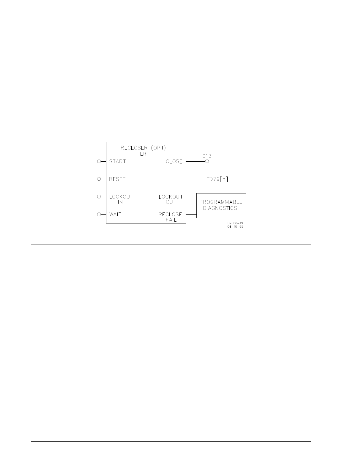
Reclosing Functions
A Reclosing Function is available in the BE1-BPR relay that can operate in parallel with the breaker
failure logic. All inputs are programmable using the BESTlogic LR command. When reclosing is enabled,
output 13 (O13) is designated at the reclose (close) output and can be connected to any physical output
by using the LO command. Three reclosing shots are available.
Separate time delays are programmable through the front panel or serial port by using the TD79
command. Time delay settings are available for each shot (TD791, TD792, and TD793), for the reset
timer (TD79R), reclose fail timer (TD79F) and a maximum reclose cycle timer (TD79M). Lockout and
reclose fail diagnostic flags are set/reset by the programmable diagnostics. Use the PDIAG command to
program separate outputs for lockout and reclose fail. The reclosing state (RESET, WAIT, TIMING, or
LOCKOUT) can be viewed from the front panel recloser status screen in the relay status menu or by
using the STATUS command.
There are four reclose function inputs, three available outputs, and one mode programmable feature
(TYPE). The inputs and outputs are shown in Figure 2-15.
Figure 2-15. Reclosing Logic Circuit
PREPROGRAMMED LOGIC DESCRIPTION
BE1-BPR relays are factory programmed with protection schemes that provide breaker failure protection
for most systems. These preprogrammed breaker failure logic schemes are described in the following
paragraphs. The programmable logic equations are not provided in this description. See Section 5,
Programmable Logic, for information on the description and use of the programmable logic as well as
application hints for programming custom logic.
Breaker Failure Logic 1 for Standard Relays (BFL1)
BFL1 logic (shown in Figure 2-16) provides the following application features.
1. Three-Pole Tripping BF Logic (No input or output latch-in provided). Three BFI inputs are available at
IN3, IN4, and IN5 to start delay timer T1. If the BFI inputs are not reset by the time timer 1 times out
and either the phase (F1) or neutral (F2) fault detector is picked up, then BFO1 and BFO3 will close
(OUT1 and OUT3), tripping the backup breakers. Refer to the breaker failure timing diagram in
Section 1 for information on setting the delay timer.
2. No Current BF Logic (No input or output latch-in provided). Some faults may not provide current to
the CTs (i.e. internal transformer failures). In that case two additional BFI inputs are available (IN6
and IN7) to start delay timer T2. These inputs are not supervised by a fault detector. If the BFI input is
not reset by the time the timer times out, BFO2 (OUT2) will close tripping the backup breakers. Refer
to the breaker failure timing diagram in Section 1 for information on setting the delay timer.
3. Trip Coil Status Monitor. Preprogrammed logic is provided using IN1 to provide breaker status and
IN2 for trip coil continuity. Refer to Application Data in this section for further details on the circuit
operation.
4. Breaker Arc Protection. Preprogrammed logic is provided using fault detector 3 (F3) for the MAF fault
detector, IN1 for breaker status, and OUT4 for the arc detector output. Refer to Application Data in
this section for further details on the circuit operation.
2-12 BE1-BPR Application 9272000990 Rev J
Page 37

5. Retrip Output. A Retrip output is provided to give a backup trip signal to the breaker trip coil. This can
either provide a separate path to a single trip coil or be hooked to the backup trip coil if available.
6. Alarm Output. An Alarm output is provided to signal relay failure or diagnostic alarm.
Figure 2-16. BFL1 Logic
Breaker Failure Logic 2 for Standard Relays (BFL2)
BFL2 logic (shown in Figure 2-17) provides the following application features.
1. Three-Pole Tripping BF Logic (Features: Output latch-in provided and Control timer limits operational
window). Three BFI inputs are available at IN3, IN4, and IN5 to start delay timer T1. If the BFI inputs
are not reset by the time timer 1 times out and either the phase (F1) or neutral (F2) fault detector is
picked up, BFO1-3 will close (OUT1-3), tripping the backup breakers. A control timer (T3) is used to
limit the breaker failure window of opportunity. Refer to the breaker failure timing diagram in Section 1
for information on setting the delay and control timers.
2. Single-Pole Tripping BF Logic (Features: Output latch-in provided and Control timer limits operational
window). If single-pole tripping is used, two additional BFI inputs are available (IN6 and IN7) to start
delay timer T2. These inputs are only supervised by the phase fault detector (F1). If the BFI (IN6 and
IN7) inputs are not reset by the time the timer T2 times out and the phase fault detector (F1) is still
picked up, the BFO outputs (OUT1-3) will close, tripping the backup breakers. Control timer, T3 is
used to limit the breaker failure window of opportunity. Refer to the breaker failure timing diagram in
Section 1 for information on setting the delay and control timers.
Neutral fault detector F2 is not used to supervise the single-pole BF logic because F2 is still picked up
by the phase imbalance after the fault clears. Three-phase BF logic is inhibited during this period
because there is no 3-phase BFI input active. For single-pole tripping, the phase pickup (PU1) must
be set above maximum load levels.
9272000990 Rev J BE1-BPR Application 2-13
Page 38

3. Trip Coil Status Monitor. Preprogrammed logic is provided using IN1 to provide breaker status and
IN2 for trip coil continuity. Refer to Application Data in this section information for further details on
the circuit operation.
4. Breaker Arc Protection. Preprogrammed logic is provided using fault detector 3 (F3) for the MAF fault
detector, IN1 for breaker status, and OUT4 for the arc detector output. Refer to Application Data in
this section for further details on the circuit operation.
5. Retrip Output. A RETRIP output is provided to give a backup trip signal to the breaker trip coil. This
can either provide a separate path to a single trip coil or be hooked to the backup trip coil if available.
6. Alarm Output. An Alarm output is provided to signal relay failure or diagnostic alarm.
Figure 2-17. BFL2 Logic
Breaker Failure Logic 3 for Standard Relays (BFL3)
BFL3 logic (shown in Figure 2-18) provides the following application features.
1. Three-Pole Tripping BF Logic (Features: Input/output latch-in provided and Control timer limits
operational window). Three BFI inputs are available at IN3, IN4, and IN5 to start delay timer T1. If the
BFI inputs are not reset by the time timer 1 times out and either the phase (F1) or neutral fault
detector (F2) is picked up, then BFO1-3 closes (OUT1-3), tripping the backup breakers. A control
timer (T3) is used to limit the breaker failure window of opportunity and latch-in the BFI inputs. Refer
to the breaker failure timing diagram in Section 1 for information on setting the delay and control
timers.
2. Single-Pole Tripping BF Logic (Features: Input/Output latch-in provided and Control timer limits
operational window). If single-pole tripping is used, two additional BFI inputs are available (IN6 and
IN7) to start delay timer T2. These inputs are only supervised by the phase fault detector (F1). If the
BFI (IN6 and IN7) inputs are not reset by the time the timer T2 times out and the phase fault detector
2-14 BE1-BPR Application 9272000990 Rev J
Page 39

(F1) is still picked up, the BFO outputs (OUT1-3) will close, tripping the backup breakers. Control
timer, T3 is used to limit the breaker failure window of opportunity. Refer to the breaker failure timing
diagram in Section 1 for information on setting the delay and control timers.
Neutral fault detector (F2) is not used to supervise the single-pole BF logic because F2 is still picked
up by the phase imbalance after the fault clears. Three-phase BF logic is inhibited during this period
because there is no 3-phase BFI input active. For single-pole tripping, the phase pickup (PU1) must
be set above maximum load levels.
3. Trip Coil Status Monitor. Preprogrammed logic is provided using IN1 to provide breaker status and
IN2 for trip coil continuity. Refer to Application Data in this section information for further details on
the circuit operation.
4. Breaker Arc Protection. Preprogrammed logic is provided using fault detector 3 (F3) for the MAF fault
detector, IN1 for breaker status, and OUT4 for the arc detector output. Refer to Application Data in
this section for further details on the circuit operation.
5. Retrip Output. A retrip output is provided to give a backup trip signal to the breaker trip coil. This can
either provide a separate path to a single trip coil or be hooked to the backup trip coil if available.
6. Alarm Output. An Alarm output is provided to signal relay failure or diagnostic alarm.
Figure 2-18. BFL3 Logic
Breaker Failure Logic 1 for Enhanced Relays (BFL1E)
BFL1E logic (shown in Figure 2-19) provides the following application features.
1. Three-Pole Tripping BF Logic (No input or output latch-in provided). Three BFI inputs are available at
IN3, IN4, and IN5 to start delay timer T1. If the BFI inputs are not reset by the time timer 1 times out
and either the phase fault detector (F1) or neutral fault detector (F2) is picked up, then BFO1 (OUT1)
9272000990 Rev J BE1-BPR Application 2-15
Page 40

closes, tripping the backup breakers. Refer to the breaker failure timing diagram in Section 1 for
information on setting the delay and control timers.
2. No Current BF Logic (No input or output latch-in provided). Some faults may not provide current to
the CTs (i.e. internal transformer failures). In this case, a BFI input is available (IN6) to start delay
timer T2. This input is not supervised by a fault detector. If the BFI input is not reset by the time the
timer times out, BFO2 (OUT2) closes, tripping the backup breakers. Refer to the breaker failure
timing diagram in Section 1 for information on setting the delay and control timers.
3. Trip Coil Status Monitor. Preprogrammed logic is provided using IN1 to provide breaker status and
IN2 for trip coil continuity. Refer to Application Data in this section for further details on the circuit
operation.
4. Breaker Arc Protection. Preprogrammed logic is provided using fault detector 3 (F3) for the MAF fault
detector, IN1 for breaker status and OUT4 for the arc detector output. Refer to Application Data in this
section for further details on the circuit operation.
5. Block Reclose Output. Preprogrammed logic is provided using breaker resistor protection output
(O13) to drive the block reclose (BR) output (OUT3). Refer to Application Data in this section for
further details on the circuit operation.
6. Retrip Output. A retrip output is provided to give a backup trip signal to the breaker trip coil. This can
either provide a separate path to a single trip coil or be hooked to the backup trip coil if available.
7. External Fault Trigger. The enhanced BE1-BPR relay provides the ability to save the COMTRADE
fault records for twelve events in memory at one time. An external fault trigger is provided to allow
other multiple units to record the same event.
8. Alarm Output. An alarm output is provided to signal relay failure or diagnostic alarm.
Figure 2-19. BFL1E Logic
2-16 BE1-BPR Application 9272000990 Rev J
Page 41

Breaker Failure Logic 2 for Enhanced Relays (BFL2E)
BFL2E logic (shown in Figure 2-20) provides the following application features.
1. Three-Pole Tripping BF Logic (Output latch-in provided and Control timer limits operational window)
Three BFI inputs are available at IN3, IN4, and IN5 to start delay timer T1. If the BFI inputs are not
reset by the time Timer 1 times out and either the phase (F1) or neutral (F2) fault detector is still
picked up, then BFO1-2 will close (OUT1-2), tripping the backup breakers. Control timer (T3) is used
to limit the breaker failure window of opportunity. Refer to the breaker failure timing diagram in
Section 1 for information on setting the delay and control timers.
2. Single-Pole Tripping BF Logic (Features: Output latch-in provided and Control timer limits operational
window). If single-pole tripping is used, a BFI input is available (IN6) to start delay timer T2. This input
is only supervised by the phase fault detector (F1). If the BFI input (IN6) is not reset by the time the
timer T2 times out and the phase fault detector (F1) is picked up, the BFO outputs (OUT1-2) closes,
tripping the backup breakers. Control timer, T3 is used to limit the breaker failure window of
opportunity. Refer to the breaker failure timing diagram in Section 1 for information on setting the
delay and control timers.
Neutral fault detector F2 is not used to supervise the single-pole BF logic because F2 is still picked up
by the phase imbalance after the fault clears. Three-phase BF logic is inhibited during this period
because there is no 3-phase BFI input active. For single-pole tripping, the phase pickup (PU1) must
be set above maximum load levels.
3. Trip Coil Status Monitor. Preprogrammed logic is provided using IN1 to provide breaker status and
IN2 for trip coil continuity. Refer to Application Data in this section for further details on the circuit
operation.
4. Breaker Arc Protection. Preprogrammed logic is provided using FD3 (F3) for the MAF fault detector,
IN1 for breaker status and OUT4 for the arc detector output. Refer to Application Data in this section
for further details on the circuit operation.
5. Block Reclose Output. Preprogrammed logic is provided using breaker resistor protection output
(O13) to drive the block reclose (BR) output (OUT3). Refer to Application Data in this section for
further details on the circuit operation.
6. Retrip Output. A Retrip output is provided to give a backup trip signal to the breaker trip coil. This can
either provide a separate path to a single trip coil or be hooked to the backup trip coil if available.
7. External Fault Trigger. The enhanced BE1-BPR relay provides the ability to save COMTRADE fault
records for twelve events in memory at one time. An external fault trigger is provided to allow other
multiple units to record the same event.
8. Alarm Output. An Alarm output is provided to signal relay failure or diagnostic alarm.
9272000990 Rev J BE1-BPR Application 2-17
Page 42

Figure 2-20. BFL2E Logic
Breaker Failure Logic 3 for Enhanced Relays (BFL3E)
BFL3E logic (shown in Figure 2-21) provides the following application features.
1. Three-Pole Tripping BF Logic (Features: Input/Output latch-in provided and Control timer limits
operational window). Three BFI inputs are available at IN3, IN4, and IN5 to start delay timer T1. If the
BFI inputs are not reset by the time timer 1 times out and either the phase (F1) or neutral (F2) fault
detector is picked up, BFO1-2 (OUT1-2) closes, tripping the backup breakers. A control timer (T3) is
used to limit the breaker failure window of opportunity and latch-in the BFI inputs. Refer to the breaker
failure timing diagram in Section 1 for information on setting the delay and control timers.
2. Single-Pole Tripping BF Logic (Features: Input/Output latch-in provided and Control timer limits
operational window). If single-pole tripping is used, a BFI input is available (IN6) to start delay timer
T2. This input is only supervised by the phase fault detector (F1). If the BFI input (IN6) is not reset by
the time the timer T2 times out and the phase fault detector (F1) is picked up, BFO2 output closes,
tripping the backup breakers. Control timer, T3 is used to limit the breaker failure window of
opportunity. Refer to the breaker failure timing diagram in Section 1 for information on setting the
delay and control timers.
Neutral fault detector (F2) is not used to supervise the single-pole BF logic because F2 is still picked
up by the phase imbalance after the fault clears. Three-phase BF logic is inhibited during this period
because there is no 3-phase BFI input active. For single-pole tripping, the phase pickup (PU1) must
be set above maximum load levels.
3. Trip Coil Status Monitor. Preprogrammed logic is provided using IN1 to provide breaker status and
IN2 for trip coil continuity. Refer to Application Data in this section for further details on the circuit
operation.
2-18 BE1-BPR Application 9272000990 Rev J
Page 43

4. Breaker Arc Protection. Preprogrammed logic is provided using fault detector 3 (F3) for the MAF fault
detector, IN1 for breaker status, and OUT4 for the arc detector output. Refer to Application Data in
this section for further details on the circuit operation.
5. Block Reclose Output. Preprogrammed logic is provided using breaker resistor protection output
(O13) to drive the block reclose (BR) output (OUT3). Refer to Application Data in this section for
further details on the circuit operation.
6. Retrip Output. A retrip output is provided to give a backup trip signal to the breaker trip coil. This can
either provide a separate path to a single trip coil or be hooked to the backup trip coil if available.
7. External Fault Trigger. The enhanced BE1-BPR relay provides the ability to save COMTRADE fault
records for twelve events in memory at one time. An external fault trigger is provided to allow other
multiple units to record the same event.
8. Alarm Output. An alarm output is provided to signal relay failure or diagnostic alarm.
Figure 2-21. BFL3 Logic
9272000990 Rev J BE1-BPR Application 2-19
Page 44

This page intentionally left blank.
2-20 BE1-BPR Application 9272000990 Rev J
Page 45

SECTION 3 • HUMAN-MACHINE INTERFACE
TABLE OF CONTENTS
SECTION 3 • HUMAN-MACHINE INTERFACE ....................................................................................... 3-1
INTRODUCTION.................................................................................................................................... 3-1
FRONT PANEL ...................................................................................................................................... 3-1
Figures
Figure 3-1. Front Panel HMI ...................................................................................................................... 3-1
Tables
Table 3-1. Front Panel HMI Component Descriptions
............................................................................... 3-2
9272000990 Rev J BE1-BPR Human-Machine Interface i
Page 46

This page intentionally left blank.
ii BE1-BPR Human-Machine Interface 9272000990 Rev J
Page 47

SECTION 3 • HUMAN-MACHINE INTERFACE
P0053-06
A
B
C
D
E
F
G
H
I
J
K
M
L
INTRODUCTION
This section illustrates and describes the BE1-BPR human-machine interface (HMI). The HMI consists of
controls, indicators, and communication connectors located on the front and rear panels of the relay.
FRONT PANEL
Figure 3-1 shows the front panel HMI components of the vertical-mount BE1-BPR. Horizontal-mount
relays share the same HMI components and differ only in component layout. Table 3-1 describes the
function of each component called out in Figure 3-1.
Figure 3-1. Front Panel HMI
9272000990 Rev J BE1-BPR Human-Machine Interface 3-1
Page 48

Table 3-1. Front Panel HMI Component Descriptions
Locator Description
A
B
C
D
E
F
G
Power Indicator. This green LED lights when operating power is applied to the relay.
Clock Indicator. This red LED lights to indicate that the real-time clock has not been set.
50PU Indicator. This red LED lights when one or more instantaneous overcurrent pickup
settings are exceeded.
Alarm Indicator. This red LED lights when a diagnostic problem occurs within the relay.
Target Indicator. This red LED lights when one or more output relays are energized and
target information has been saved to nonvolatile memory. Detailed target information is
available through the Target menu of the display (Locator M).
Communication Port 0 (COM 0). Communication with the relay can be achieved by
connecting a communication cable between this female RS-232 serial port and a computer
terminal or PC. Simple ASCII commands can be transmitted and received by using terminal
emulation software such as Windows
HyperTerminal.
The front port is provided for local, temporary communication with the relay. A rear RS-232
port (Port 1A) and a rear RS-485 port (Port 1B) are intended as remote, long-term
communication connections. Section 6, Communications, provides detailed information
about using the communication ports to communicate with the relay.
Program Key (PROG). Pressing this pushbutton enters the Program mode which allows
you to make settings changes. If password protection is enabled, a password may need to
be entered before settings changes are allowed.
Settings changes are saved by pressing and holding the Program key for two seconds. The
Save screen is then displayed and you are prompted to save your changes to nonvolatile
memory or exit the Program mode without saving changes.
H
J
K
L
Edit Key (+/-). This pushbutton enters the Program mode. Pressing the Edit key increments
a setting number or character to the next higher value in the sequence. Pressing the
Program key followed by the Edit key reverses the direction of settings changes so that
pressing the Edit key decrements a setting to the next lower value in the sequence. The
direction of change is reversed until any key other than the Edit key is pressed.
I
View/Select (►) Key. This pushbutton selects the top level of the next menu branch for
viewing. Pressing the View/Select key when the last available menu branch is reached,
returns the display to the first available menu branch.
When operating in Program mode, pressing the View/Select key selects the next number or
string to change.
View/Select (▼) Key. This pushbutton selects the next lower screen of the current menu
branch for viewing. Pressing the View/Select key when the last available screen is reached,
returns the display to the top screen of the menu branch.
When operating in Program mode, pressing the View/Select key selects a different screen
for making settings changes.
Reset Key. Pressing this pushbutton displays the top screen of the menu branch that you
are viewing. Pressing the Reset key while viewing targets or a diagnostic screen resets
(clears) the target or diagnostic information.
When operating in Program mode, pressing and holding the Reset key for two seconds exits
the Program mode without saving any settings changes.
Identification Label. This label lists the relay part number, serial number, rated sensing
input current, and power supply voltage.
3-2 BE1-BPR Human-Machine Interface 9272000990 Rev J
Page 49

Locator Description
M
Display. The display consists of a two line by 16 character liquid crystal display (LCD) with
backlighting. Information such as targets, metering values, communication parameters, the
active logic scheme name, and diagnostic information is displayed by the LCD. The LCD is
also used when making settings changes at the relay front panel. Section 4, Functional
Description, Software Functional Description, provides more information about obtaining
information and making settings changes through the display.
9272000990 Rev J BE1-BPR Human-Machine Interface 3-3
Page 50

This page intentionally left blank.
3-4 BE1-BPR Human-Machine Interface 9272000990 Rev J
Page 51

SECTION 4 • FUNCTIONAL DESCRIPTION
TABLE OF CONTENTS
SECTION 4 •FUNCTIONAL DESCRIPTION ............................................................................................ 4-1
GENERAL .............................................................................................................................................. 4-1
HARDWARE FUNCTIONAL DESCRIPTION ........................................................................................ 4-1
Inputs .................................................................................................................................................. 4-1
Circuit Operation ................................................................................................................................ 4-1
Outputs ............................................................................................................................................... 4-3
SOFTWARE FUNCTIONAL DESCRIPTION ......................................................................................... 4-4
Introduction ......................................................................................................................................... 4-4
Changing Parameters Using the Front Panel .................................................................................... 4-8
Changing Parameters Using Communication Ports........................................................................... 4-9
Password Protection ........................................................................................................................ 4-11
Target Data....................................................................................................................................... 4-14
Relay Setup ...................................................................................................................................... 4-15
Output Hold Function ....................................................................................................................... 4-25
Relay Status ..................................................................................................................................... 4-25
Breaker Status .................................................................................................................................. 4-29
Timer Log ......................................................................................................................................... 4-35
Fault Log (Enhanced Relays Only) .................................................................................................. 4-39
Maintenance ..................................................................................................................................... 4-43
Figures
Figure 4-1. Functional Block Diagram ....................................................................................................... 4-2
Figure 4-2. Enhanced BE1-BPR Menu Display Screens .......................................................................... 4-6
Figure 4-3. Standard BE1-BPR Menu Display Screens ............................................................................ 4-7
Figure 4-4. Accessing PROGRAM Mode from HMI .................................................................................. 4-8
Figure 4-5. Exiting PROGRAM Mode from HMI
Figure 4-6. Timer Circuit .......................................................................................................................... 4-20
Figure 4-7. Reclosing Logic Circuit .......................................................................................................... 4-22
Figure 4-8. Tc and Ti Timing Diagram ..................................................................................................... 4-33
Figure 4-9. 52 Contact Designation ......................................................................................................... 4-33
Figure 4-10. Output 13 Logic ................................................................................................................... 4-34
Figure 4-11. Margin Log Timing Sequence ............................................................................................. 4-37
Figure 4-12. Margin Log Logic ................................................................................................................. 4-37
Figure 4-13. H, L Alarm Conditions ......................................................................................................... 4-38
Tables
Table 4-1. Alarm States
Table 4-2. Output States
Table 4-3. Password Write Access Areas
........................................................................................ 4-9
............................................................................................................................. 4-3
........................................................................................................................... 4-4
............................................................................................... 4-12
9272000990 Rev J BE1-BPR Functional Description i
Page 52

This page intentionally left blank.
ii BE1-BPR Functional Description 9272000990 Rev J
Page 53

SECTION 4 •FUNCTIONAL DESCRIPTION
GENERAL
BE1-BPR Breaker Protection Relays are microprocessor-based devices that provide breaker failure
protection, optional fault recording, and diagnostic monitoring of breaker wear and breaker resistor
overheating. This section describes the hardware and software functional descriptions.
HARDWARE FUNCTIONAL DESCRIPTION
BE1-BPR relays are available in a horizontal, 19-inch, rack-mount configuration or a vertical, panel-mount
configuration. Two latches secure the chassis assembly in the case. The chassis assembly can be
removed from the case by releasing the two latches and pulling the spring loaded, retracting handle on
the front panel. It is not necessary to disturb system wiring when removing a BE1-BPR relay from the
case. A transparent front cover protects the relay but allows access to frequently used front panel
controls.
The hardware functional description is divided into three categories: inputs, circuit operation, and outputs.
Inputs
There are five types of inputs to the BE1-BPR relay. They are:
• Operating Power
• Contact Sensing
• Current Sensing
• Keyboard
• Serial Ports RS-232/RS-485
Operating Power
Operating power for the internal circuitry is applied to the internal, isolated, switching power supply.
Nominal operating power is either 48/125 VDC or 125/250 VDC and is determined by the relay part
number shown in Section 1, General Information, Specifications.
Contact Sensing
Seven external contact sensing inputs accept external stimulus to initiate BE1-BPR relay actions. Voltage
applied to the contact sensing inputs must fall within the relay DC power supply input voltage range. If the
power supply of the relay has an ac source, a separate dc source must be used for the contact sensing
input voltage. Three contact sensing inputs (IN1 through IN3) are individually isolated. IN4 and IN5 are
isolated from other circuits but share a common return. IN6 and IN7 are also isolated from other circuits
but share a common return.
Current Sensing
Monitored line and neutral currents are applied to internal current transformers (CTs) and stepped down
to internal circuit levels. The internal CTs provide isolation from the monitored line currents.
Keyboard
A keyboard (illustrated in Section 3) provides limited local programming capability and the ability to select
a number of status and diagnostic menu screens.
Serial Ports RS-232/RS-485
Serial communication ports at the front and rear of the BE1-BPR relay provide complete programming
capability and remote access for diagnostics, relay setup, and relay control.
Circuit Operation
The microprocessor continually monitors itself to ensure proper operation. Separate, independent circuitry
monitors the power supply and the microprocessor to ensure that any problem in these areas
automatically takes the BE1-BPR off-line and activates the alarm output. Relay circuit functions illustrated
in Figure 4-1 are described in the following paragraphs.
9272000990 Rev J BE1-BPR Functional Description 4-1
Page 54

Figure 4-1. Functional Block Diagram
Power Supply
The isolated, switching power supply generates ±12 Vdc, +5 Vdc, and an isolated +5 Vdc. If the +5 Vdc
digital supply falls outside the defined tolerance, then the microprocessor is reset by the power supply
supervisory circuit. This reset takes the relay off-line and lights the Alarm LED. High capacitance on the 5
Vdc supply maintains oscillography and fault record data stored in RAM (enhanced units only) for 24
hours (at 25°C) when operating power is lost or removed.
Watchdog Timer
If the microprocessor fails for any reason, output pulses to the watchdog timer stop. The watchdog timer
will then take the relay off-line, and light the Alarm LED, and close the alarm output.
Opto-Isolators
Opto-isolators in the contact sensing input circuits provide isolation from the external power supply which
provides power to the contact input circuits.
4-2 BE1-BPR Functional Description 9272000990 Rev J
Page 55

Debounce Logic
Outputs from the contact sensing circuits are debounced by the microprocessor using programmable
recognition and debounce times. Debounce logic is programmable only through the communication ports.
Anti-Aliasing Filter and Analog to Digital Converter
Stepped-down inputs from each CT are converted to a voltage signal and filtered by a low-pass antialiasing filter. The digitized input signal is then passed to the microprocessor for processing.
Programmable Fault Detector Logic
Each monitored current is digitized, digitally filtered, and the 50/60 hertz rms value for each input is calculated. The filtered value is compared to the appropriate pickup setting. If the filtered value is greater than
the pickup setting, then a fault detector logic flag (F1, F2, or F3) is set for use by the output logic section.
If the fault detector logic is programmed as an instantaneous overcurrent pickup (filter type 1 or 3), the
50PU LED is turned on. If the fault detector logic is programmed as a moving average current detector,
(filter type 2), the 50PU LED is not turned on.
Programmable Timer Logic
Up to six programmable, independent timers are available in the breaker fail logic. The timers can be
programmed to act as a control timer or delay timer.
Programmable Recloser Logic
A one to three shot recloser function is available with separate timers for reset, reclose fail, and maximum
cycle time.
Microprocessor Based Programmable Logic
Microprocessor software provides the capability of a programmable logic controller (PLC) to control the
outputs. Output control equations take the form of simple Boolean equations. Contact inputs (Ix), fault
detectors (Fx), timer outputs (Tx), and outputs relays (Ox) act as variables in the equations. The microprocessor based programmable logic is covered in detail in Section 5, BESTlogic Programmable Logic.
Outputs
There are five types of BE1-BPR outputs:
• Alarm relay
• Output relays
• Targets
• Liquid crystal display (LCD)
• Serial ports RS-232/RS-485
Alarm Relay
Output relay OA is operated (energized) by the programmable logic section when logic equation LOA is
false. Table 4-1 lists the two LOA states and the corresponding hardware states.
Table 4-1. Alarm States
Logic Equation
LOA
0 Off Energized Open
1 On De-Energized Closes
The normally-closed configuration of output relay OA holds the Alarm output contacts in the open state
when LOA=FALSE (coil energized) and closes the contacts when LOA=TRUE (coil de-energized). If the
power supply voltage decreases below a predetermined level or the microprocessor watchdog times out,
the output contacts close (coil de-energizes). The software Alarm output (OA) is logically ORed with the
hardware logic power sensor and watchdog timer. Either input can trigger the Alarm output independently
from the software logic. The microprocessor-based relay logic
HMI Alarm
LED
Alarm Relay
OA
cannot disable this hardware protection.
Alarm
Contacts
9272000990 Rev J BE1-BPR Functional Description 4-3
Page 56

Output Relays
Output relays O1 through O5 are operated (energized) by the programmable logic section when the
corresponding logic equation is true. Table 4-2 lists the two logic equation states and the corresponding
hardware states.
Table 4-2. Output States
Logic Equation LO1 - LO5 Output Relay O1 - O5 O1 - O5 Contacts
0 De-energized Open
1 Energized Closed
Output relay O1 is a high-speed output with maximum operate time of 5 milliseconds.
Targets
Detailed target information about the inputs and outputs is displayed by the Targets menu screen.
Whenever any of the target output relays energize, the front panel Target LED lights. Target information is
latched in non-volatile memory if the output is programmed as latching. To reset the Target LED, operate
the front panel Reset pushbutton or enter the RESET command through a serial communication port. The
PTARGET command programs output relays as target relays.
Liquid Crystal Display (LCD)
A two line by 16 character, LCD shows targets, setup, status, and diagnostic information and allows
provides programming capability. LED backlighting illuminates the LCD screen.
Serial Ports RS-232/RS-485
Serial communication ports at the front and rear of the BE1-BPR provide total programming capability and
remote access for diagnostic, relay setup, and relay control.
SOFTWARE FUNCTIONAL DESCRIPTION
Most relay settings may be adjusted using the front panel keyboard and display. However, to program the
relay logic, change the breaker configuration data, time and date format, CT data, and request reports,
the front or rear communications port must be used. In general, tasks that are not easily performed at the
front panel should be done through the communication ports.
Introduction
Relay diagnostic and setup information is organized in a menu format when viewed using the front panel
display. Figure 4-2 shows the menu progression from startup to maintenance for an enhanced BE1-BPR.
Figure 4-3 shows the menu progression for a standard BE1-BPR. The right arrow key is used to scroll
through the available menu screens and the down arrow key is used to access menu sub-screens. When
using a communication port, the relay is programmed using ASCII software commands. Information about
software commands is available by using the HELP command. The HELP command provides a list of
available commands or information and syntax regarding a specific command along with an example of
its use.
HELP
Parameter Comments
Commands Information HMI Menu Branch: N/A
Cmd HELP or H returns information about using the HELP command. HELP1 or H1
provides a list of relay commands. HELP<cmd> or H<cmd>, where <cmd> is a
specific command, returns information on the usage and format of the
command and an example of its use.
4-4 BE1-BPR Functional Description 9272000990 Rev J
Page 57

HELP Command
Purpose: Obtains helpful information about communication port commands.
Syntax: HELP [x/<cmd>]
Comments: No access area password is required to use the HELP command.
NOTE
Relay responses in all examples are displayed in a Courier typeface.
HELP Command Example:
Obtain information about using the PU command.
HELP PU
Purpose: Read/Change fault detector Pickup level and cycles
Syntax : PU[#[=<level (A)>[,<cycles>]]]
Example: PU1 or PU1=6.2 or PU3=0.5,10
Startup and Menu Selection
When the relay is turned on, the startup screen is displayed for two seconds and then defaults to the
TARGETS menu screen. At this time, the relay is at the menu level. Operating the front panel right arrow
key causes each menu screen to be displayed in succession. The display order is:
0. TARGETS 4. TIMER LOG
1. RELAY SETUP 5. FAULT LOG (enhanced units only)
2. RELAY STATUS 6. MAINTENANCE
3. BREAKER STATUS
After MAINTENANCE, the menu returns to the TARGETS screen.
Viewing Screens
All display menu screens are easily viewed using the right and down arrow keys. For example, there are
three sub-screens under the RELAY SETUP screen. Delay settings for timers T4, T5, and T6 (TD4, TD5,
and TD6) are shown in the third sub-screen. To view these settings, use the right arrow key until you see
the RELAY SETUP menu screen on the front panel display. Use the down arrow key until you see the
third sub-screen. Follow this same procedure to view any sub-screen in any menu.
Default Screen
Default screens are automatically displayed if no keys have been pressed for five minutes. The standard
default screen is the target screen. The user has the option to default to another screen (such as current
display, breaker operations counter, time/date) when no targets are active by using the PDISPLAY command. More information about the PDISPLAY command is provided in the Maintenance sub-section.
9272000990 Rev J BE1-BPR Functional Description 4-5
Page 58
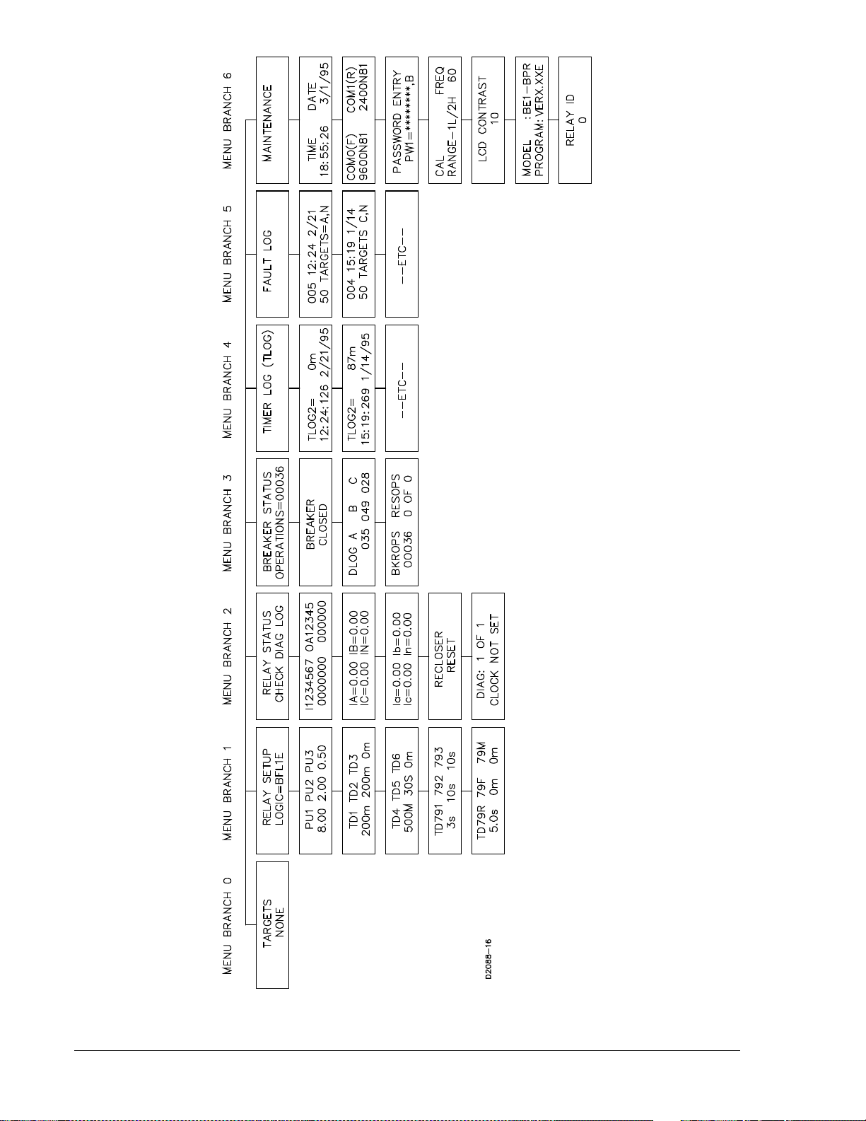
Figure 4-2. Enhanced BE1-BPR Menu Display Screens
4-6 BE1-BPR Functional Description 9272000990 Rev J
Page 59

Figure 4-3. Standard BE1-BPR Menu Display Screens
9272000990 Rev J BE1-BPR Functional Description 4-7
Page 60

Changing Parameters Using the Front Panel
Changing settings through the front panel consists of an ACCESS-CHANGE-SAVE-CONFIRM cycle.
Changing parameters requires that you access the programming mode, select the appropriate screen(s),
program (make) the change(s), save new relay setting(s), and confirm that the programming is completed
before the changes are actually made. The relay continues to use the previous setting parameters until all
changes are made and the new settings are saved. It is important to change all relay parameters and
then execute the SAVE command. Doing this prevents partial or incomplete protection schemes from
being implemented.
As an example, in order to change the overcurrent pickup setting for PU2 from 4.4 amperes to 6.3 amperes, the following procedures would be used.
Accessing PROGRAM Mode
To access the PROGRAM mode, press the PROG key. If password protection is enabled, you will be
prompted to enter the password before continuing. For now, let's assume that we have not enabled
password protection. An access level screen will be displayed momentarily showing your programming
access level and then the original display will return and a cursor will be visible.
Selecting the Menu Screen
To change a parameter (relay setting), select the menu screen by using the right arrow key until the
appropriate menu screen is shown. With the RELAY SETUP screen displayed, press the down arrow key
once to display the pickup sub-screen. If PROGRAM mode has been enabled, the cursor will be under
the first digit for the PU1 setting. Figure 4-4 illustrates entering the PROGRAM mode.
Figure 4-4. Accessing PROGRAM Mode from HMI
4-8 BE1-BPR Functional Description 9272000990 Rev J
Page 61

Making the Change
Press the right arrow key. The cursor moves to the second digit for PU1. Continue to press the right arrow
key until the cursor is under the units digit for PU2. To change the 4 to a 6, press the EDIT +/- key two
times. With the 6 displayed, press the right arrow key to position the cursor under the tenths digit. To
change the 4 to a 3, two methods are available. The quickest method is to press the PROG key to make
the EDIT +/- key decrement. Now press the EDIT +/- key and the 4 changes to a 3. The next key that is
pressed, other than the EDIT +/- key, changes the EDIT +/- key back to the increment function. Another
method is to press (increment) the EDIT +/- key nine times until the 3 is displayed. With 6.3 displayed for
PU2, we now need to exit the PROGRAM mode and save the changes. While in the PROGRAM mode,
the BE1-BPR relay remains on-line and the changes do not take effect until the PROGRAM mode is
exited and the changes are saved.
Saving Changes and Exiting PROGRAM Mode
To save the settings and exit the PROGRAM mode, press and hold the PROG key for two seconds. The
SAVE CHANGES? (Y/N) - N
EDIT +/- key to select Y for yes. Press the PROG key and the relay will go off-line briefly while the new
settings are saved and the BE1-BPR relay reinitializes.
screen appears and the cursor is under the N (see Figure 4-5). Press the
Figure 4-5. Exiting PROGRAM Mode from HMI
Changing Parameters Using Communication Ports
Changing settings through a communication port requires an ACCESS-CHANGE-SAVE-CONFIRM cycle.
The operator uses the ACCESS command to obtain a program (change) access level. Different
passwords give access to change different parameters.
ACCESS Command
Purpose: Reads or changes access area so that programming or settings changes can be made.
Syntax: ACCESS[=<password>]
ACCESS Command Examples:
1. Obtain area two access.
ACCESS=OPENUP
ACCESS GRANTED
AREA 2
9272000990 Rev J BE1-BPR Functional Description 4-9
Page 62

2. Read the current programming access area.
ACCESS
AREA 2
ACCESS
Comments
This command is used to gain access to an access area before making programming or
settings changes. The access areas are available:
ACCESS AREA 1: Access is provided by password 1 (PW1). PW1 allows write access to all
ACCESS AREA 2: Access is provided by password 2 (PW2). PW2 permits changes to be
ACCESS AREA 3: Access is provided by password 3 (PW3). PW3 allows breaker related
ACCESS AREA 4: Access is provided by password 4 (PW4). PW4 allows control or relay
Access to an area is granted when the appropriate password is entered. If password protection
is disabled in one or more areas, then no password is required to gain access to the
unprotected levels. If a valid password is entered, the relay responds with the access area
provided by that password. If an invalid password is entered, an error message is returned.
After changes are made, the new data must be saved with the SAVE command. The operator must
confirm that the programming is completed before the changes are actually made. If no password
protection is used, it is still necessary to obtain programming/change access in order to protect against
accidental changes. If password protection is disabled, then ACCESS=BPR or any other string will be
accepted in place of a password.
Programming changes access HMI Menu Branch: N/A
setting and operating registers with no restrictions.
made to relay protection settings.
settings changes to be made.
outputs for testing purposes.
SAVE
Comments
This command is used at the end of a programming or settings changing session to save the
changes made. When the SAVE command is entered, the relay responds with a confirmation
message (ARE YOU SURE (Y/N)?). If Y is entered, programming or settings changes are
saved to non-volatile memory, the programming mode is exited, and the relay is returned to an
on-line condition. Entering N exits the programming mode without saving changes and returns
the relay to an on-line condition.
SAVE Command
Purpose: Saves programming or settings changes, exits the programming mode, and returns the
Syntax: SAVE
Comments: Once the SAVE command is executed, password access is lost.
SAVE Command Example:
Change the PU2 setting from 4.4 amperes to 6.3 amperes using the following sequence of commands.
ACCESS=BPR<CR> Provides access to programming mode.
ACCESS GRANTED LEVEL 1 Relay response.
PU2=6.3<CR> Changes the pickup setting.
SAVE<CR> End programming.
ARE YOU SURE (Y/N)? Relay verification.
Exit programming mode and save changes HMI Menu Branch: N/A
relay to an on-line condition.
4-10 BE1-BPR Functional Description 9272000990 Rev J
Page 63

Y<CR> Enter Y to save the data.
RELAY OFF_LINE
CHANGES SAVED The new pickup setting for PU2 is now 6.3A.
RELAY ON_LINE
The <CR> character at the end of typed lines stands for carriage return and represents pressing the Enter
key. For simplicity, it will no longer be shown in the examples, but each line
carriage return.
The relay will typically respond with a '>' if the command entered was received and executed. A '?' is
returned and possibly an error message if the command could not be executed.
It is important to make
prevents a partial or incomplete protection scheme from being implemented.
Settings changes made during a programming session can be discarded by using the QUIT command.
The QUIT command will restore all settings, exit the programming mode, and return the relay to the online condition.
all
changes to relay parameters before executing the SAVE command. Doing this
be terminated with a
must
QUIT
Comments
This command causes all changes performed in the programming mode to be lost and the
previous parameters to be restored. When the QUIT command is entered, the relay responds
with a confirmation message (ARE YOU SURE (Y/N)?). If Y is entered, programming or
settings changes are lost, the programming mode is exited, and the relay is returned to an online condition. Entering N returns the relay to the programming mode.
QUIT Command
Purpose: Exits the programming mode and returns the relay on-line without saving any changes.
Syntax: QUIT
Comments: Once the QUIT command is executed, password access is lost.
QUIT Command Example:
Exit the programming mode without saving any setting changes made.
QUIT
ARE YOU SURE (Y/N)?
Y
RELAY OFF-LINE
CHANGES LOST
RELAY ON-LINE
Exit programming mode without saving changes HMI Menu Branch: N/A
Password Protection
BE1-BPR relays provide password protection against unauthorized changes to relay setting parameters
and operating registers. Four different passwords of one to eight characters may be used. Each password
provides a different access capability.
Gaining write access in an access area with password protection requires that the correct password be
entered. If password protection is enabled and no password has been entered or if an incorrect password
has been entered, you will be prompted to enter a new password before any changes can be made.
If a different access area password is entered while another area password is already in effect, the new
access area will replace the current one. If a password is reprogrammed, it will not become effective until
a SAVE command is given. When a password is entered, the relay looks for matching passwords. Access
is granted to all areas with passwords that match the entered password.
The password for access area 1 allows write access to all setting and operating registers with no
restrictions. The access area 2 password permits changes to be made to relay protection settings. The
9272000990 Rev J BE1-BPR Functional Description 4-11
Page 64

password for access area 3 allows breaker related settings changes to be made. The access area 4
password allows control of relay outputs for testing purposes. General access settings can be accessed
by using passwords for areas 1, 2, or 3. Table 4-1 provides a summary of the write commands associated
with each access area. Table 4-3 also lists the menu branch of the equivalent functions that are
accessible through the front panel HMI. When password protection is enabled, the correct password is
required to make changes associated with each command. A password is never required to read
information associated with a command.
Table 4-3. Password Write Access Areas
NA = Not Applicable ∗ = Enhanced units only
Access
Area
0 - 4 DATE Set clock date 5 6
0 - 4 DIAG Reset alarms 2 2
0 - 4 FLOG
0 - 4 RESET Reset targets or reset other logs if specified 0 0
0 - 4 TIME Set time clock 5 6
1, 2, 3 TRIGGER Set trigger logic NA NA
0 - 4 TRIGGER
1 CAL Calibrate relay 5 6
1 FREQ Set the nominal system frequency 5 6
1 ID Set the multi-drop communications address NA NA
1 LF Set fault detector function block logic NA NA
1 LI Set input conditioning logic NA NA
1 LN Set user programmable logic name NA NA
1 LO Set output logic expressions NA NA
1 LOGIC Set which logic scheme is active NA NA
1 LR Set recloser function block logic NA NA
1 LT Set timer function block logic NA NA
1 PW Set password security 5 6
1, 2 PTARGET Set targeting function NA NA
1, 2 PU Set fault detector pickups 1 1
1, 2 TD Set timer delays 1 1
1, 2 TD79 Set recloser time delays 1 1
1, 3 BKRCON
1, 3 BKROPS Set up breaker operations monitoring NA NA
1, 3 BKRRES Set up breaker resistor monitoring NA NA
1, 3 DLOG
1, 2, 3 COM Set up communications 5 6
1 CT Set CT ratios NA NA
1, 2, 3 PCLK Set clock display format NA NA
1, 2 PDIAG Set alarm diagnostics NA NA
1, 2, 3 PDISPLAY Set default HMI display NA NA
1, 2, 3 PHOLD Set output hold timers NA NA
1, 2, 3 POSC
1, 2, 3 PTLOG Set timer log operation NA NA
1, 2, 3 SNAME Set substation and circuit name for COMTRADE
1, 4 OUT Override output logic and pulse output contacts NA NA
Command Function
Reset fault log ∗
Trigger oscillography record ∗
Set up breaker contact duty monitoring ∗
Reset breaker contact duty registers ∗
Set number of oscillographic fault records ∗
reports ∗
HMI Menu Branch
Standard
Models
NA 5
NA NA
NA NA
NA 3
NA NA
NA NA
Enhanced
Models
4-12 BE1-BPR Functional Description 9272000990 Rev J
Page 65

A second dimension of security is provided. Passwords may be configured to operate at different access
ENTER PASSWORD
∗∗∗∗∗∗∗∗
ports. An access port designation of F allows access only at the front panel (COM 0 serial port and the
front panel display/keyboard). An access port designation of R allows access only at the rear panel (COM
1 serial port). An access port designation of B allows access at both the front and rear panels. Password
protection for a specific access area may be disabled by programming the password to be 0 (zero).
Password protection for all passwords may be disabled by programming PW1 as a 0. If a particular
password is disabled, then no prompts to "ENTER PASSWORD” will be given when programming the
protected functions for that password.
Password Protection Example:
If the following password protection is desired:
• Area 1 changes to only be performed from the front panel by personnel with the password OPENUP.
• Area 2 changes to be performed with no password required but only from the front panel.
• Area 3 changes to be performed from either the front or rear panels by personnel with the password
BKRGRP.
• Area 4 control to be accessed from the front panel by personnel with the password TEST.
The passwords are programmed as follows:
ACCESS=BPR
ACCESS GRANTED LEVEL 1
PW1=OPENUP,F Password for Area 1.
PW2=0,F Password for Area 2.
PW3=BKRGRP,B Password for Area 3.
PW4=TEST,F Password for Area 4.
SAVE
ARE YOU SURE (Y/N)? Relay verification.
Y Enter Y to save the data.
RELAY OFF_LINE
CHANGES SAVED The new passwords are now operational.
RELAY ON_LINE
The Programming a New Password sub-section provides another example of changing password
protection.
Entering an Access Password at the Front Panel
To change settings at the front panel, first enter the PROGRAM mode by pressing the PROG key. The
password prompt appears as shown.
In the password prompt, “∗∗∗∗∗∗∗∗” represents the password and the cursor is under the first (leftmost)
character. To enter a password, press the +/- key until the correct character is displayed. Press the right
arrow key to move to the next password character and press the +/- key until the correct character is
displayed. Continue to enter password characters until the correct password is entered. If the password is
less than eight characters, use the down arrow key to end the entry. After the eighth character is entered,
the password entry screen is automatically ended. One of three possible screens appears for two
seconds before the original menu screen reappears. The three screen possibilities are:
If password is accepted:
9272000990 Rev J BE1-BPR Functional Description 4-13
LEVEL_
If password is rejected:
ACCESS DENIED ACCESS GRANTED
If programming conflict:
ACCESS DENIED
ACCESS CONFLICT
Page 66

The programming conflict message will appear if program mode has already been entered through one of
the rear serial ports. The relay allows programming only at one source at a time.
Entering an Access Password through Communication Ports
When entering a password through communication ports, you must enter the password using the
ACCESS command (Example ACCESS=OPENUP). Passwords entered through a terminal keyboard are
not case sensitive. If a valid password is entered, an ACCESS GRANTED LEVEL x message is
displayed. If an invalid password is entered, an ACCESS DENIED message is displayed.
Target Data
The Targets screen is usually the most often viewed screen. Because of this, the TARGETS screen is the
default screen. Viewing order or progression through the menu screens is based on the expected
frequency of use.
TARGETS Screen
The TARGETS screen shows the status of the input and output targets that are latched in memory at the
time a target output closes. When the front panel TARGET LED is lit, the TARGETS screen will show the
latched target data. The display will show an “I” and the numbers of any contact inputs ON at the time the
output occurred and an O and the numbers of the outputs that were on.
An example of a TARGETS screen with inputs 1, 4, and 5 closed and output contacts 2 and 3 closed is
shown below.
TARGETS
I-145 O-23
The targets reset if the inputs or outputs are no longer active when the RESET key is pressed. Target
data is saved in nonvolatile memory, so target data is retained when relay operating power is lost.
Target information may be programmed, viewed, or reset through the communications port. Targets can
be viewed using the TARGET command.
TARGET
Comments
This command reports target data for inputs 1 through 7 and outputs 1 through 5. Output target
data must be programmed to latch by the PTARGET command. Once an output target has
latched, the inputs associated with the output will be shown as targets. Pressing the HMI Reset
key or entering TARGET=0 will clear the latched target data.
TARGET HMI Screen Example:
TARGET Command
Purpose: Reads input and output target information.
Syntax: TARGET
Comments: No access area password is required to view or reset target data.
TARGET Command Examples:
1. Read the target information.
TARGET
I-6, O-2
2. Reset the targets.
TARGET=0
4-14 BE1-BPR Functional Description 9272000990 Rev J
Target information HMI Menu Branch: 0
TARGETS
I-6 O-2
Page 67

Targets are reset using the RESET command.
RESET
Parameter Parameter Selections Comments
log none (targets)
RESET Command
Purpose: Clears latched data.
Syntax: RESET[<log>]
Comments: No access area password is required to clear latched data. Entering RESET without a log
Inputs and outputs may be programmed as targets through the communication port with the PTARGET
command. Inputs and outputs not included in the PTARGET mask will not give a target indication when
the input or output is active.
PTARGET
Parameter Parameter Selections Comments
Data erasure HMI Menu Branch: N/A
This command clears data once the source of the
tar (targets)
flog (fault log)
tlog (timer log)
diag (relay diagnostics)
parameter will clear the target information.
Target operation and display HMI Menu Branch: N/A
target has been cleared. Data can be cleared through
the HMI by viewing the data on the HMI screen and
pressing the Reset key.
iiiiiii 0 (no target)
1 (target)
ooooo 0 (no target)
1 (target)
PTARGET Command
Purpose: Reads or programs the target operation and display.
Syntax: PTARGET[=<iiiiiii>,Kooooo>]
Comments: Access area 1 or 2 password is required to change settings.
PTARGET Command Example:
Program outputs 1, 2, and 3 to target.
PTARGET=0000000,11100
Relay Setup
BE1-BPR protective functions are controlled by the operational logic that is programmed into the relay
and the setting values associated with that logic. BE1-BPR relays with standard options have three
preprogrammed breaker failure logic schemes that are stored in nonvolatile program memory. BE1-BPR
relays with enhanced options have six preprogrammed breaker failure logic schemes that are stored in
non-volatile program memory. A logic scheme can be selected using the front panel controls or through
serial port communications.
9272000990 Rev J BE1-BPR Functional Description 4-15
Input target status for I1 through I7. Leftmost
digit represents the status for I1. Rightmost
digit represents the status for I7. An input
target status will not latch unless the related
input target is programmed active. Inputs may
be targeted for diagnostic purposes when an
output target is latched.
Output target status for OUT1 through OUT5.
Leftmost digit represents the status for OUT1.
Rightmost digit represents the status for
OUT5.
Page 68

The RELAY SETUP menu screen shows the unique name of the protection logic scheme selected. Other
TD79R 79F 79M
TD1 TD2 TD3
schemes may be selected pressing the EDIT +/- key with the cursor under the logic name. The relay will
scroll through the logic names stored in memory. The fault detector pickup and timer delay settings are
displayed on the RELAY SETUP sub-screens. To change the relay pickup or timer settings, use the same
techniques described in this section, under Changing Parameters.
Example of typical RELAY SETUP menu screens:
RELAY SETUP menu screen:
RELAY SETUP
LOGIC = BFL1
Sub-screen 1:
PU1 PU2 PU3
6.00 1.50 0.05
Sub-screen 2:
150m 50m 600m
Sub-screen 3:
TD4 TD5 TD6
30s 1.0s 10s
Sub-screen 4:
TD791 792 793
100m 1.0s 5.0s
Sub-screen 5:
10.0s 0m 0m
RELAY SETUP information can be reviewed or programmed through the communications ports as well.
• The operational logic may be viewed or changed using the LOGIC command. A custom logic scheme
can be defined using the LN, LI, LF, LR, LT, and LO commands. The equations defining an existing
logic scheme may be reviewed using the LINFO command. All relay settings can be reviewed using
the SHOWSET command.
• Pickup settings can be viewed or changed using the PU command. The PU command can also be
used to view or set the number of cycles used for the moving average filter if digital filter 2 operation
is selected when defining the fault detector logic (LF).
• Time delay settings can be viewed or changed using the TD command.
• Recloser timer delay settings can be viewed or changed using the TD79 command.
• The CT ratios for phase and neutral CTs can be viewed or changed using the CT command.
• The 200 millisecond minimum hold time for the output contacts can be enabled or disabled.
Transformer Ratios
The CT command allows the relay to be matched to your system’s external current transformers.
Separate settings are provided for the phase and neutral CTs. CT ratio adjustment is not provided
through the HMI.
4-16 BE1-BPR Functional Description 9272000990 Rev J
Page 69

CT
Parameter Parameter Selection Range Increment Default
Current transformer ratio information HMI Menu Branch: N/A
t P (phase CT)
N (neutral CT)
ratio pri:sec
or pri/sec
or calculated ratio
CT Command
Purpose: Read or change the current transformer ratio settings.
Syntax: CT[t][=<ratio>]
Comments: An access area 1, 2, or 3 password is required to change settings. The CT ratio can be
entered in three different formats but is always reported as the calculated ratio. The CTP
and CTN values affect the primary current metering values, the contact duty log (DLOG)
calculations, and the COMTRADE fault record current levels.
CT Command Examples:
1. Enter a neutral CT ratio of 400:5.
CTN=80 or CTN=400/5 or CTN=400:5
2. Read the CT ratios.
CT
CTP=50; CTN=80
sec, and calculated
N/A N/A
1 - 65535 for pri,
ratio
1
CTP=1
CTN=1
Fault Detectors
Three fault detectors, F1, F2, and F3, are provided in the BE1-BPR. Each fault detector can be
configured for phase or neutral current sensing and the type of filtering. Three filtering options are
available: Instantaneous (type 1), Moving Average (type 2), and Instantaneous Three-Phase (type 3).
Type 1 Fault Detector. The type 1 fault detector provides high speed operation with a typical pickup time
of one cycle and a typical dropout time of ¼ cycle. Fault detectors F1 and F2 are programmed as Type 1
fault detectors in the preprogrammed logic schemes. Refer to Section 2, Application for a detailed
description of the Type 1 fault detector.
Type 2 Fault Detector. The type 2 fault detector provides a slower but more consistent pickup. This type
of fault detector is appropriate for applications where fault detector sensitivity of less than 0.25 amperes
(relays with 5 A current sensing) is desirable. When a Type 2 fault detector is used, the pickup (PU)
command includes a parameter for entering the number of cycles to be averaged before pickup or
dropout occurs. Refer to Section 2, Application for a detailed description of the Type 2 fault detector.
Type 3 Fault Detector. The type 3 fault detector performance is identical to the type 1 fault detector
except that all three-phase currents must be above the pickup threshold to trigger an output. Refer to
Section 2, Application for a detailed description of the type 3 fault detector.
The LF command configures each fault detector for phase or neutral protection and for high-speed or
moving- average filtering.
9272000990 Rev J BE1-BPR Functional Description 4-17
Page 70

LF
Parameter Parameter Selections Defaults
type PI (phase overcurrent)
filter 1 (1cycle RMS filter)
LF Command
Purpose: Read or change the fault detector logic of the active logic scheme.
Syntax: LF[x][=<type>,<filter>]
Comments: An access area one password is required to change settings.
LF Command Examples:
1. Program fault detector 1 as a phase overcurrent fault detector using digital filter 1.
LF1=PI,1
2. Program fault detector 2 as a neutral overcurrent fault detector using digital filter 1.
LF2=NI,1
3. Program fault detector 3 as a phase overcurrent pickup using the moving average filter (filter 2).
LF3=PI,2
Fault detector logic HMI Menu Branch: N/A
NI (neutral overcurrent)
2 (moving average filter)
3 (1 cycle RMS 3-phase filter
LF1=PI,1
LF2=NI,1
LF3=PI,2
CAUTION
A pickup setting range check is made each time logic settings are changed that
affect the fault detector pickup settings. For example, if PU1=5.00 and LF1
setting is changed from PI,1 to PI,2, the PU1 setting will automatically change
from 5.00 to 1.00 (the maximum allowable setting for a Type 2 fault detector on a
5 A unit). This kind of pickup setting adjustment can also occur if the active relay
logic is replaced with logic that has different LF settings.
The PU command sets the trip value of each fault detector and the moving average filter cycles for type 2
fault detectors.
4-18 BE1-BPR Functional Description 9272000990 Rev J
Page 71

PU
Parameter Unit of Measure Range Increment Default
Fault detector pickup levels HMI Menu Branch: 1
level
5 A CT
LFx=type,1 or 3 ∗
level
5 A CT
LFx=type,2
level
1 A CT
LFx=type,1 or 3 ∗
level
1 A CT
LFx=type,2
cycles cycles 1 to 100 1 N/A
∗ Types 1 and 3 PU settings can be set below the stated minimum settings. However, specified
accuracies will not be maintained when PU settings are set outside the setting range.
PU HMI Screen Example:
PU Command
Purpose: Read or change fault detector pickup levels.
Syntax: PU[x][=<level>,<cycles>]
Comments: x = 1 (fault detector 1), 2 (fault detector 2), or 3 (fault detector 3)
level = pickup level in amperes for fault detector x
cycles = number of moving average filter cycles
Cycles parameter is used only if an analog channel is programmed to have a moving
average filter (Lfx=type,2). See LF command information in BESTlogic Functions section.
An access area 1 or 2 password is required to change settings.
PU Command Examples:
1. Set the analog channel pickup level at 6.2 amperes.
PU1=6.2
2. Read the pickup setting for all channels.
PU
PU1=6.2; PU2=0.5; PU3=0.1,10
Amperes 0.25 to 9.99 0.01
Amperes 0.05 to 1.00 0.01
Amperes 0.05 to 2.00 0.01
Amperes 0.01 to 0.10 0.01
PU1 PU2 PU3
8.00 2.00 0.50
PU1=8.00
PU2=2.00
PU3=0.50,10
PU1=2.00
PU2=2.00
PU3=0.20,10
Timers
Six independent timers are provided in the BE1-BPR. Each timer consists of a time delay setting (TD[x]),
a start input, a reset input, and an output (T[x]). Timing starts when the start input is true and the reset
input is false. The timer runs for the duration of the time delay setting unless the reset input becomes true.
When the time delay expires, the output changes state. A timer can be configured as a delay or control
timer with independent or dependent start and reset conditions. Timers can be used to provide a
diagnostic log and/or alarm. Figure 4-6 illustrates the timer circuit components.
9272000990 Rev J BE1-BPR Functional Description 4-19
Page 72

Figure 4-6. Timer Circuit
The LT command is used to configure timers for control or delay operation and define the start and reset
logic.
LT
Parameter Parameter Selections Defaults
type C (control timer)
start any logic variable
reset any logic variable
LT Command
Purpose: Read or change timer logic.
Syntax: LT[x][=<type>,<start>,<reset>]
Comments: x = the number of the timer being read or changed (1, 2, 3, 4, 5, or 6). An access area 1
LT Command Example:
Configure timer 1 as a delay timer that is started when contact input 1 is energized and stopped when
output 6 is de-energized. Configure timer 2 as a control timer that is started when input 2 is energized and
stopped when input 2 is de-energized.
LT1=D,I1,/O6; LT2=C,I2,/I2
The TD command is used to read or enter the delay settings for each of the six timers.
TD HMI Screen Example:
Timer logic HMI Menu Branch: N/A
D (delay timer)
0 (disabled)
password is required to change settings.
LT1=D,O8,/O8
LT2=D,O9,/O9
LT3=0,0,0
LT4=D,O6,/O6
LT5=D,O12,/O12
LT6=0,0,0
TD1 TD2 TD3
150m 200m 1.0s
TD
Parameter Unit of Measure Range Increment Default
delay cycles (c)
∗ All timer settings greater than or equal to 1 second are rounded to 0.1 second resolution.
4-20 BE1-BPR Functional Description 9272000990 Rev J
Timer delays ∗
milliseconds (m)
seconds (s)
1 to 3,600 cycles
10 to 60,000 ms
1 to 60 seconds
HMI Menu Branch: 1
1 cycle
1 ms
0.1 s
TD1=150m
TD2=200m
TD3=1.0s
TD4=500m
TD5=30.0s
TD6=0m
Page 73

TD Command
Purpose: Read or change timer delay settings.
Syntax: TD[x][=<delay>]]
Comments: x = the number of the timer being read or changed (1, 2, 3, 4, 5, or 6)
Delay = the time delay in cycles (c), milliseconds (m), or seconds (s)
A setting of zero disables a timer. An access area 1 or 2 password is required to change
settings.
TD Command Example:
Set time delay 2 at 100 milliseconds and time delay 5 at 30 seconds.
TD2=100
TD5=30S
Delay Timer. When a delay timer is started, a preprogrammed time delay (TD[x]) is loaded and the timer
starts timing out. If the reset input remains false for the duration of the time delay, output T[x] will become
true and remain true until the reset input becomes true.
This type of timer is useful in a breaker failure application where the breaker failure output is delayed to
allow the primary protection elements to operate the breaker and open the circuit.
Control Timer. When a control timer is started, a preprogrammed time delay (TD[x]) is loaded and the
timer starts timing out. Output T[x] is true for the duration of the time delay setting unless the reset input
becomes true. If the reset input remains false for the duration of the time delay, the time delay will time
out and the output will become false. The timer output will remain false until the timer is reset and a new
start input is received.
A control timer can provide a window of opportunity for an operation to occur or ensure input latch-in for a
specified time.
Reclosing
The BE1-BPR reclosing function can operate in parallel with the breaker failure logic. All inputs are
programmed using the BESTlogic LR command. When reclosing is enabled, virtual output 13 (O13) is
used for the 79 Close output of the recloser function block. If reclosing is disabled, O13 is used for the
breaker resistor protection function output that is described in the Breaker Status sub-section. Figure 4-7
illustrates how the recloser and breaker resistor protection function operate if both are enabled. O13 can
be connected to any physical output by using the LO command.
Separate time delays are programmable through the front panel or serial port by using the TD79
command. Time delay settings are available for each shot (TD791, TD792, and TD793), for the reset
timer (TD79R), reclose fail timer (TD79F) and a maximum reclose cycle timer (TD79M). Lockout and
reclose fail diagnostic flags are set/reset by the recloser diagnostics and by using the command PDIAG to
program the diagnostic outputs. Separate outputs for lockout and reclose fail can be programmed.
Reclosed state (RESET, WAIT, TIMING, or LOCKOUT) can be viewed at the front panel recloser status
screen in the relay status menu or by using the STATUS command.
9272000990 Rev J BE1-BPR Functional Description 4-21
Page 74

Figure 4-7. Reclosing Logic Circuit
TD79
Parameter Unit of Measure Range Increment Default
delay milliseconds (m)
∗ All timer settings greater than or equal to 1 second are rounded to 0.1 second resolution.
TD79 HMI Screen Examples:
TD79 Command
Purpose: Read or change recloser (79) time delay settings.
Syntax: TD[x][=<delay>]
Comments: x = the number of the timer being read or changed where:
1 = TD791, the reclose shot 1 time delay
2 = TD792, the reclose shot 2 time delay
3 = TD793, the reclose shot 3 time delay
R = TD79R, the reset time delay
F = TD79F, the reclose fail time delay
M = TD79M, the maximum reclose operation time
Delay = the time delay in cycles, milliseconds, or seconds
A setting of zero disables a timer. An access area 1 or 2 password is required to change
settings.
Reclose timer delays ∗
seconds (s)
cycles (c)
TD791 792 793
50m 1.0s 5.0s
10 - 999 ms
1 - 600 seconds
1 - 36014 (60 Hz)
1 - 30000 (50 Hz)
TD79R 79F 79M
120m 0m 0m
HMI Menu Branch: 2
1 ms
0.1 s (1-100 s)
1.0 s (100-600 s)
1 cy
TD791=50m
TD792=1.0s
TD793=5.0s
TD79R=120s
TD79F=0m
TD79M=0m
4-22 BE1-BPR Functional Description 9272000990 Rev J
Page 75

TD79 Command Example:
Set reclose shot 1 at 3 cycles to allow for arc de-ionization. Set reclose shot 2 at 2.5 seconds and disable
reclose shot 3. Set the reset time at 30 seconds, the fail time at 2 minutes, and the maximum reclose time
at 2.5 minutes.
TD791=3C; TD792=2.5S; TD793=0; TD79R=30S; TD79F=120S; TD79M=150S
There are four inputs to a reclose function, three outputs, and one mode programmable feature (TYPE).
The inputs and outputs are shown in Figure 4-7.
Recloser Inputs. Each input is fully programmable using the logic recloser command (LR) which allows
each input to be defined as a BESTlogic logic term. The function of each input is:
START: Starts the reclose sequence if the RESET input is not true.
RESET: Begins reset timing and opens the CLOSE output. If RESET remains true for the reset
time delay (TD79R), the recloser goes to the reset state and the recloser shot counter is
reset.
WAIT: Stops the reclose sequence at any point. The reclose sequence is inhibited as long as
the wait input is present. When the wait input is removed, the sequence continues from
the point that it was stopped.
DTL: Drives the reclose function immediately to the lockout state. Lockout has precedence
over all other inputs. When lockout is removed and the breaker is closed, the recloser
begins reset timing. When lockout is removed and the breaker is open, the recloser
remains in the lockout state.
LR
Parameter Parameter Selections Defaults
type 0 (disabled)
start any logic variable
reset any logic variable
wait any logic variable
lockout any logic variable
LR Command
Purpose: Reads or programs the recloser input logic.
Syntax: LR[=<type>,<start>,<reset>,<wait>,<lockout>]
Comments: Access area 1 password is required to change setting.
Example 1: Define a recloser that is initiated by any true signal to the breaker and reset when the 52a
LR=1,O5,I1,I6,I7
Example 2: Define the same logic except that a 52b input is connected to I1 instead of the 52a and
LR=1,O5,/I1,0,I7
Recloser input logic HMI Menu Branch: N/A
1 (standard recloser)
2 (power-up reclose)
The recloser is enabled only when
the type selection is 1 or 2 and the
start and reset logic is programmed.
contact closes. Given: Previous BESTlogic definitions have defined a logic scheme that
has all BFI TRIP signals driving O5 for a retrip function, and have defined I1 to be a 52a
input, I6 to be a wait input, and I7 to be a drive to lockout input.
there is o wait input.
9272000990 Rev J BE1-BPR Functional Description 4-23
Page 76

Recloser Outputs. There is a CLOSE output on O13 and diagnostic status flags for reclose fail and
lockout. Output O13 and the diagnostics for reclose fail and lockout can be programmed to drive output
relay contacts by using the LO and PDIAG commands.
The function of each output or flag is defined as:
CLOSE: The reclose output contacts close at the end of each reclose time delay. They open
when the RESET input shows that the breaker has closed, when the reclose fail timer
times out, or when the recloser goes to LOCKOUT or the WAIT input is asserted.
RECLOSE FAIL: The reclose fail diagnostic flag is set when the reclose fail timer times out and
remains set until the recloser goes to the reset state.
LOCKOUT: The lockout flag is set when the recloser goes to LOCKOUT and remains set until the
recloser goes to the reset state. The recloser goes to LOCKOUT if more than the
maximum number of shots programmed is initiated before the recloser returns to the
reset state, if the Drive to Lockout (DTL) input is true, or if RECLOSE FAIL is true.
Reclosing Mode (TYPE). Reclosing mode controls the reclosing sequence on powerup. There are three
modes of operation and one is selected by setting the TYPE in the LR command to 0, 1, or 2.
NOTE
After the programmable logic is changed or the time delay settings are changed,
the recloser initializes as described in the Reclosing Mode, TYPE 1 or TYPE 2.
TYPE 0 disables the reclosing function.
TYPE 1 requires that after power-up, the RESET input logic stay true for the reset time delay (TD79R) or
the recloser automatically goes to LOCKOUT.
TYPE 2 allows the recloser to initiate the first programmed reclose operation after power-up if power was
lost when the recloser was in the reset state and at power-up, the RESET logic is false and the START
logic is true. If RESET goes true and stays true for the reset time delay (TD79R), the recloser
automatically goes to RESET. This type of reclosing mode may be appropriate if the BE1-BPR relay is
powered-up from the station service.
Recloser Operation. There are a maximum of three reclose shots, each with a programmable time delay.
The three time delays can be set from 10 to 999 milliseconds in 1 milliseconds increments, 1 to 99
seconds in 0.1 second increments, or 100 to 600 seconds in 1 second increments. A setting of zero for
reclose shot 1, 2, or 3 will send the relay to lockout when that reclose shot is reached in the reclosing
sequence.
If the recloser is in the reset state upon receiving a START input signal (RI) and RESET is false (52a or
/52b), the reclose logic issues a reclose output (O13). The output occurs after the TD791 time delay
setting. If the breaker closes and then opens again before the reset timer is timed out, a reclose output
occurs after the second time delay. The third reclose output occurs in a similar manner. The recloser goes
immediately to the lockout state on the fourth breaker trip.
Reset timer (TD79R) begins timing out when the RESET logic becomes true (breaker closes). The reset
timer is reset when the breaker trips. If the reset timer times out while the breaker is closed, the recloser
goes to the reset state. Setting the reset time delay at zero will give an instantaneous reset and eliminate
reclose shots 2 and 3 from the reclose sequence.
If enabled, the reclose fail timer (TD79F) starts whenever a reclose output is given and stops when the
RESET logic indicates the breaker has closed. It is used to limit the duration of the reclose output signal.
If the reclose fail timer times out before the RESET logic becomes true, the recloser sets the reclose fail
diagnostic flag. The reclose fail function can be inhibited by setting the RECLOSE FAIL time delay
(TD79F) to zero (0).
If the total reclosing time between reset states exceeds the maximum reclose cycle timer (TD79M) setting
(excluding time while in the WAIT state), the recloser goes to the lockout state. The lockout alarm
diagnostic flag is set whenever the recloser goes to the lockout state. A time delay setting of zero will
inhibit the maximum reclose timer functions.
4-24 BE1-BPR Functional Description 9272000990 Rev J
Page 77

Output Hold Function
Ic=2.13 In=0.00
IC=1.28K IN=0.00K
0000000 000000
Protection outputs will usually have a minimum hold time to ensure that the protective relay contact does
not interrupt the trip coil current and the breaker close output will stay closed until the recloser shows that
the breaker has closed. The PHOLD command provides a 200-millisecond output hold time that can be
enabled or disabled for each output.
PHOLD
Parameter Parameter Selections Defaults
##### 0 = no minimum hold time
PHOLD Command
Purpose: Read or program the output hold timer mask.
Syntax: PHOLD [=<#####>]
Comments: Access area password 1, 2, or 3 required to change settings. Default setting is 11111.
PHOLD Command Example:
Disable the minimum hold time for output 3. Enable the minimum hold time for outputs 1, 2, 4, and 5.
PHOLD=11011
Relay Status
For diagnostic purposes, the RELAY STATUS menu screen provides a means of checking the status of
the current inputs, contact sensing inputs, output contacts, recloser, and relay diagnostics. This information can also be obtained using the STATUS, I, and DIAG commands.
Typical RELAY STATUS screens are shown below on the left. An example of a report obtained using the
STATUS command is shown below on the right.
Output hold timers HMI Menu Branch: N/A
Each digit of the PHOLD parameter
1 = 200 ms minimum hold time
represents an output. The leftmost
digit represents OUT1. The rightmost digit represents OUT5.
Typically, the 200 millisecond hold
time will be enabled for all outputs
except those used for reclosing.
RELAY STATUS
menu screen
Sub-screen 1 Input
and Output Contact
Status
Sub-screen 2
Primary Current
Metering Values
Sub-screen 3
Secondary Current
Metering Values
Sub-screen 4
Recloser Status
Sub-screen 5+
Diagnostic
Message Screen(s)
9272000990 Rev J BE1-BPR Functional Description 4-25
RELAY STATUS
I1234567 OA12345
IA=1.28K IB=1.28K
Ia=2.13 Ib=2.13
RECLOSER RESET
DIAG: NONE
IA=3.00KA; IB=3.00KA
IC=3.00KA; IN=0.00KA
I (1-7) = 0100000
T (1-6) = 000000
F (1-3) = 001
O (A,1-15) = 0000000000000000
RECLOSER RESET
BREAKER CLOSED
DIAG: 1 to 1 TIMER ALARM
Page 78

The RELAY STATUS menu branch shows the status of all inputs and outputs as well as any diagnostic
Ia=2.13 Ib=2.13
IA=1.28K IB=1.28K
alarms detected by the relay. Sub-screen 1 indicates the status of all input contacts and output contacts.
Zeroes are shown for input contacts that are open and outputs that are de-energized. Ones are shown for
input contacts that are closed and outputs that are energized. Sub-screen 2 indicates the primary current
values of phase A, B, C and Neutral. Sub-screen 3 indicates the secondary current values of all phases
and neutral. Sub-screen 4 provides the recloser status. RESET, TIMING, LOCKOUT, or WAIT is
displayed if the recloser is active. RECLOSER OFF is displayed when the recloser is disabled. Subscreen 5 shows any diagnostic alarms recorded by the relay. Once the alarms are viewed and corrected,
they can be cleared by pressing the Reset key or by entering DIAG=0 or RESET DIAG. A listing and
description of all diagnostic alarms is provided in the DIAG and PDIAG command summary tables.
The STATUS command provides status information about the primary current values, contact sensing
inputs, timer/counters, fault detectors, hardware and virtual outputs, recloser, and active diagnostic flags.
STATUS
Comments
This command returns all current input values and system status registers. The status registers
indicate the state of contact sensing inputs I1 through I7, timers/counters T1 through T6, fault
detectors F1 through F3, outputs OA, and O1 through O15, recloser status, breaker status, and
any active diagnostic flags.
STATUS Command
Purpose: Returns a report of inputs, outputs, and internal relay status.
Syntax: STATUS
Comments: No access area password is required for reporting functions.
STATUS Command Example:
Obtain a relay status report.
STATUS
IA=3.00KA; IB=3.00KA; IC=3.00KA; IN=0.00KA
I (1-7) = 0100000
T (1-6) = 000000
F (1-3) = 001
O (A,1-15) = 0000000000000000
RECLOSER RESET
BREAKER CLOSED
DIAG: 1 to 1 TIMER ALARM
The I command returns the primary current values of the phase A, B, C, and neutral inputs.
Relay status report HMI Menu Branch: 2, 3
Comments
This command returns the primary value of all current inputs. The primary current value is
calculated using the transformer ratio entered using the CT command. Individual currents can
be read by entering I<phase>, where <phase> is A, B, C, or N.
I HMI Screen Examples:
4-26 BE1-BPR Functional Description 9272000990 Rev J
I
Measured current values HMI Menu Branch: 2
Primary Current Secondary Current
IC=1.28K IN=0.00K
Ic=2.13 In=0.00
Page 79

I Command
Purpose: Reads the primary current value of all or individual phases.
Syntax: I[<phase>]
Comments: No access area password is required for reporting functions. Primary and secondary
current values are available through HMI menu branch 2.
I Command Examples:
1. Read Phase B current.
IB
3.23KA
2. Read all primary currents.
I
IA=3.23KA; IB=3.23KA; IC=3.23KA; IN=0.00KA
The DIAG command reads or resets any diagnostic alarms recorded by the relay.
DIAG
Parameter Description
Non-Maskable
Alarms
Maskable
Alarms
Diagnostic alarms HMI Menu Branch: 2
RAM ERROR: Static RAM read/write error
ROM ERROR: EPROM program memory checksum error
uP ERROR: Microprocessor self test error
EEPROM ERROR: EEPROM read/write error
EEDATA ERROR: EEPROM data checksum error
ADC ERROR: Analog to digital converter error
CALIBRATION ERROR: Relay not calibrated or calibration checksum error
POWER SUPPLY ERROR: Power supply out of tolerance
ALARM LOGIC (OA): Alarm logic (OA equation) was true
TIMER ALARM (TL): Timer alarm setting exceeded (refer to PTLOG
Command)
CONTACT DUTY ALM (DL): Contact duty maximum (DMAX) exceeded
(refer to BKRCON Command)
BKROP >1 SEC (BKR): Breaker operation (clearing) time was greater than 1
second
POWER RESET (RST): Power supply to microprocessor has been reset
CLOCK NOT SET (CLK): Real time clock not set
RECLOSE FAIL (RF): Reclose attempt failed
DIAG Command
Purpose: Reads or resets diagnostic information.
Syntax: DIAG[=0]
Comments: No access area password is required to read or reset diagnostic information. Entering
DIAG=0 will reset all diagnostics that can be reset.
DIAG Command Example:
View any diagnostic alarms.
DIAG
TIMER ALARM
9272000990 Rev J BE1-BPR Functional Description 4-27
Page 80

The PDIAG command is used to configure the diagnostic alarms.
PDIAG Command
Purpose: Reads or programs service diagnostic alarms.
Syntax: PDIAG[=<DIAG1 mask>,<DIAG2 mask>]
Comments: Access area level password 1, 2, or 3 is required to change settings. A diagnostic flag is
enabled by a 1 and disabled by a 0. DIAG1 drives virtual output 14 (O14) AND DIAG2
drives virtual output 15 (O15). Entering PDIAG returns the diagnostic mask for O14 and
O15.
PDIAG
Parameter Range Parameter Selections
DIAG1
mask
DIAG2
mask
Programmable diagnostic alarms HMI Menu Branch: N/A
0 or 1
0 or 1
<(OA)(TL)(DL)(BKR)(RST)(CLK)(RF)(LO)>
where:
OA - Flag is set when LOA logic becomes true. Flag is reset
when the diagnostic alarms are cleared and the DIAG=0
command is sent. Allows a logic expression written to LOA to be
latched and reported.
TL - Flag is set when any TLOG alarms occur. Flag is reset
using the DIAG=0 command.
DL - Flag is set when any DLOG is ≥ 100% of DMAX. Flag is
reset when the DLOG value is reset.
BKR - Flag is set when the breaker takes more than 1 second
to interrupt the phase current after the breaker is opened. Flag
is reset when the DIAG=0 command is used.
RST - Flag is set when the microprocessor is reset due to a loss
of power or watchdog timer operation. Flag is reset when the
DIAG=0 command is used.
CLK - Flag is set when the time and date have not been set.
Flag is reset when either the time or date is set.
RF - Flag is set when the Reclose Fail Alarm occurs. Flag is
reset when the breaker closes.
LO - Flag is set when the recloser goes to lockout. Flag is reset
when the recloser comes out of lockout.
PDIAG Command Example:
Program virtual output 14 to go high if the recloser lockout (LO) flag is set. Program virtual output 15 to go
high if the alarm logic (OA), timer log (TLOG), duty log (DL), or reclose fail (RF) flags are set.
PDIAG=00000001,11100010
The TEST command provides the same diagnostic information as the DIAG command plus the software
checksum and relay on-line/off-line status.
TEST
Comments
This command retrieves diagnostic data from the relay. This data includes diagnostic alarms,
the software checksum, and whether the relay is on or off line. The diagnostic alarm
information retrieved by the TEST command is the same information displayed by the DIAG
command. The TEST command is read only; diagnostic alarms should be reset using the DIAG
command.
4-28 BE1-BPR Functional Description 9272000990 Rev J
Diagnostic data HMI Menu Branch: N/A
Page 81

TEST Command
OPERATIONS=00345
DLOG A B C
102 63 25
BREAKER
CLOSED
OPERATIONS=00345
Purpose: Reads diagnostic data.
Syntax: TEST
Comments: No access area password is required to read diagnostic data.
TEST Command Example:
Verify the software checksum.
TEST
RELAY ON-LINE
DIAG: 1 OF 2 CLOCK NOT SET
PROGRAM CHECKSUM: 3C7E
Breaker Status
Breaker status information is contained in three diagnostic logs. They are the breaker operations log, the
breaker resistor operations log, and the breaker contact duty log (enhanced relays only). Breaker status
information may also be viewed or configured through a communication port using the DLOG, BKRCON,
BKRRES, BKROPS, and STATUS commands.
Breaker Status Menu Screens
An example of typical breaker status screens are provided below.
BREAKER STATUS
menu screen
Sub-screen 1
Breaker Status
Screen
Sub-screen 2 Log
Contact Duty
Sub-screen 3
Breaker Operations
and Breaker
Resistor Operations
Breaker Status Screen
The breaker status screen shows the current position of the breaker (OPEN/CLOSED) based on the logic
defined by the BKROPS command. Breaker position is also reported by the STATUS command.
BKROPS
Parameter Unit of Measure Range Increment Default
BREAKER STATUS
BKROPS RESOPS
000345 0 of 0
Breaker operations status HMI Menu Branch: 3
(Enhanced Relays Only)
BKROPS HMI Screen Example:
9272000990 Rev J BE1-BPR Functional Description 4-29
# operations breaker operations 0 to 99,999 1 00,000
52a/b contact logic N/A N/A N/A /I1
BREAKER STATUS
Page 82

BKROPS Command
60
1
2
1
50,00010DMAX
2
⋅⋅⋅=
6
10208DMAX ⋅=
Purpose: Read or change breaker operations data.
Syntax: BKROPS[=<#operations>,<breaker close logic>]
Comments: An access area 1 or 3 password is required to change settings. Breaker close logic is
defined using any contact sensing input that is true when the breaker is closed. True logic
indicates a closed breaker; false logic indicates an open breaker. # operations
increments when the breaker closes.
BKROPS Command Example:
Set the breaker operations counter at zero and use contact input 1 to sense the breaker status (52a
contact finger).
BKROPS=0,I1
Breaker Contact Duty Diagnostics (Enhanced Relays Only)
Breaker contact duty log, DLOG, is stored in nonvolatile memory and contains the approximate duty or
contact wear on each pole (phase) of the breaker represented as a percentage of a maximum, DMAX. A
52a or 52b input is required for this diagnostic and the timing relationship between the auxiliary contact
finger and the main breaker contacts should be known for maximum accuracy. The duty percentage value
for each pole can be programmed through the front panel controls or through a communication port using
the DLOG command. The log may be reset to zero after maintenance or set at a specific percentage
value when the relay is put into service by using the DLOG command.
The duty value for each pole of the breaker, D[p], is compared against a maximum value, DMAX. If D[p]
for any pole of the breaker exceeds DMAX, a diagnostic alarm is set to true and remains set until the D[p]
value for the appropriate pole(s) are reset. Using the programmable logic, a virtual output can drive an
output relay to provide an indication that the breaker needs service. To do this, use the PDIAG command
to enable the DLOG diagnostic alarm to turn on O14 or O15 when DLOG[p] exceeds 100 percent. Then
use the LO command to use O14 or O15 to drive output O1 - O5.
2
DMAX is programmable in amperes-squared seconds (A
times 10
6
A2-S would be entered as 2.0E6). DMAX is an approximation that can be refined as further
-S) in exponential notation. For example, 2
experience with a particular type of breaker is obtained. Changing DMAX will automatically update the
value in the DLOG to a new percentage based on the new DMAX value.
Users may find it difficult to obtain a setting for DMAX since no standard recommends the interrupting
duty limits for breakers. The following formula is offered as a guide and should be superseded by
manufacturers data when available.
If a breaker manufacturer published the maximum number of safe operations (N), at the full-rated
interrupting current value (Ir), assume that the average arcing time (ta) is ½ cycle.
The duty limit setting is then calculated as
For example, if I
equals 50 kA, N equals 10, n equals 2, and the frequency equals 60 Hz, DMAX is
r
INDMAX
⋅=
r
⋅⋅
F12
n
1
calculated as follows.
A lower value of DMAX may be selected until a reliable correlation is found between contact wear and the
accumulated interrupted duty.
The duty on each pole is accumulated and calculated as follows for each breaker opening:
where: ∞
D[p] = ∑(CTP • I[p][n])
2
(Tbo)
N=1
D[p] = Breaker duty for pole p
p = Phase identification number where 1/2/3=a/b/c
CTP = Phase current transformer step-down ratio
4-30 BE1-BPR Functional Description 9272000990 Rev J
Page 83

n = Accumulated number of breaker operation
DLOG A B C
Ti = Time delay in msec, adjustable from 0 to ±50 msec, used to compute I[p][n]
I[p][n] = The filtered RMS value of the secondary phase p current in microprocessor
memory at the time the nth breaker operation is recognized by the
microprocessor. I[p][n] will correspond to the RMS current through the breaker for
the cycle ending at Ti msec from the time that the breaker 52a or b finger contact
was recognized. See NOTE under Breaker Resistor Diagnostics.
Tbo = Breaker operate time calculate as Tbo
T = Time in msec measured by the relay from when 52a or b contact closure is
recognized to when the fault detector(s) drop out.
Tc = Fixed time in msec, adjustable for 0 to ±50 msec, entered into the relay
representing the time from when the 52a or b contact changes state to when the
main breaker contacts begin to part. A negative Tc value is entered when the 52a
or b contacts change state
positive Tc value is entered when the 52a or b contacts change state
main breaker contacts part.
contact = Input contact and logic used to define breaker in open position
Breaker Duty is reported and set in terms of percent of DMAX using the DLOG command through a
communications port or using the contact duty log sub-screen on the front panel.
after the main breaker contacts begin to part. A
the
before
DLOG
Parameter Unit of Measure Range Increment Default
YY percent 0.00 to 101.00 0.01 0.00
DLOG HMI Screen Example:
DLOG Command
Purpose: Read or change breaker contact duty log data.
Syntax: DLOG[P}[=<YY>]
Comments: P = breaker pole A, B, or C
YY = accumulated breaker pole duty as a percent of the DMAX setting
This function is available on enhanced BE1-BPR relays only. An access area 1 or 3
password is required to change settings.
DLOG Command Examples:
1. Read the contact duty log values.
DLOG
DLOGA= 92; DLOGB= 22; DLOGC= 27
2. Reset the Phase A duty log after maintenance was performed.
DLOGA=0
The breaker information used in computing the breaker contact duty is programmed through the
communication ports using the BKRCON, BKROPS, and CTP commands. Parameters for BKROPS and
CTP commands are as defined in the previous paragraphs. If DMAX is programmed as 0 (zero) the
breaker duty feature is disabled.
Breaker contact duty log data HMI Menu Branch: 3
035 049 028
9272000990 Rev J BE1-BPR Functional Description 4-31
Page 84

BKRCON
Parameter Unit of Measure Range Increment Default
Breaker duty monitoring HMI Menu Branch: N/A
DMAX
Tc Milliseconds
Ti Milliseconds
BKRCON Command
Purpose: Read or change breaker contact duty monitoring settings.
Syntax: BKRCON[=<DMAX>,<Tc>,<Ti>]
Comments: Tc is a negative value when the 52b contacts change state after the main contacts open.
Tc is a positive value when the 52b contacts change state before the main contacts open.
Ti sets the point where the last full cycle of current calculations ends and is taken relative
to the 52b status. Positive Ti is after the 52b.
This function is available on enhanced BE1-BPR relays only. An access area 1 or 3
password is required to change settings.
BKRCON Command Examples:
1. Set Tc at 6 milliseconds, Ti at 8 milliseconds, and DMAX at 10 kA-seconds.
BKRCON=1.0E4,6,8
2. Read breaker contact information
BKRCON
BKRCON=1.0E4,8,8
3. Set the Tc parameter of the BKRCON command for a breaker whose 52b contact closes 3
milliseconds after the main contacts part. Recognition time for the 52b contact has been set at 4
milliseconds using the LI command. Note that Tc is set as the sum of the 52b recognition time setting
and the 52b contact delay. (–3–4=7 ms). Set Ti for 5 milliseconds after the 52b contact is recognized.
The timing diagram is shown in Figure 4-8.
BKRCON=1.0E4,-7,5
Both Tc and Ti are referenced to that instant in time when the 52b contact is recognized. If Tc or Ti
occurs after the 52b contact is recognized, they are positive time values. Otherwise, they are negative
time values. Be sure to offset Tc and Ti by the 52b recognition time (LI command, see Section 5,
BESTlogic Programmable Logic, Contact Input Logic, Definition of Input Contact Operation).
Primary A2
seconds
0 to 6.8E38 0.001 0.000E00
0 to ±200
0 to ±200
1 0
1 0
4-32 BE1-BPR Functional Description 9272000990 Rev J
Page 85

Figure 4-8. Tc and Ti Timing Diagram
An effective Tc setting can only be made if you know when the main contacts and the 52 contacts change
state in the breaker opening cycle. Figure 4=9 shows some 52 contact designations and timing
references that may be found in some manufacturers’ literature. Typically, large variations can be found in
52a/b designs. To obtain the highest arcing time accuracy, the time relationship between the breaker
main contacts opening and the 52 contact changes of state should be measured using a travel analyzer.
Figure 4-9. 52 Contact Designation
9272000990 Rev J BE1-BPR Functional Description 4-33
Page 86

Breaker Operations Counter
The breaker operations counter logs the number of open and close cycles of the circuit breaker. The
counter increments when the breaker closes. The number of breaker operations can be viewed or set
through the communications ports using the BKROPS command or through the HMI using Breaker Status
sub-screen 3. Breaker operations can also be viewed on the Breaker Status Menu Screen. The BKROPS
command also defines the logic for determining the breaker position (open or closed). Refer to the
Breaker Status Screen sub-section for information about using the BKROPS command.
Breaker Resistor Diagnostics
Breaker-opening resistors are used on some high voltage breakers to limit the maximum interrupting
current during fault conditions. This resistor is mechanically linked to the main breaker contact so that
when the main breaker contact opens, the opening resistor is placed in series with the phase current
approximately one-half cycle before the breaker opens. Since the breaker resistor is usually much larger
than the fault resistance, the breaker resistor will tend to limit the fault current to a value based on the
primary circuit voltage divided by the breaker resistor value ( Ires = V
than the maximum short circuit rating (I
) for the breaker.
SC
/ R ). This value, Ires, will be less
LN
Typically, a breaker-opening resistor will be rated to allow a maximum number of operations (MAXOPS)
before waiting a defined reset or cooling off period. This reset period must occur before another operation
can safely be allowed. The BE1-BPR keeps track of the accumulated resistor heating by adding one
operation to the RESOPS counter for every breaker opening and subtracting one from the RESOPS
counter, <reset> minutes after the operation was logged.
The breaker resistor counter, RESOPS, stores in volatile memory the accumulated breaker operations
that are not reset. The current status of this counter is displayed on BREAKER STATUS menu,
sub_screen 2.
If reclosing is disabled and the accumulated operations equals MAXOPS, virtual output 13 (O13)
becomes true. This virtual output may be connected to an actual output by programming the logic. This
output contact can provide a block reclose output (BRO) to prevent another operation and overheating
the opening resistors. If the reclosing function is enabled, and the accumulated operations equals
MAXOPS, the block reclose signal is internally ORed with the defined WAIT logic input. This action delays
reclosing to protect the opening resistors from overheating. Figure 4-10 illustrates the logic that controls
virtual output 13 (O13) when breaker resistor protection and/or reclosing is enabled.
Figure 4-10. Output 13 Logic
4-34 BE1-BPR Functional Description 9272000990 Rev J
Page 87

NOTE
BKROPS RESOPS
If Ires is programmed, then the DUTY LOG uses that value in current (I)
calculations instead of (CTP∗I[p][n]) because it would be difficult to separate the
arcing current from the fault current prior to the resistor being inserted.
Breaker information used in the breaker resistor diagnostics is programmed using the BKRRES
command. If MAXOPS is programmed to zero, the resistor heating diagnostic is disabled.
BKRRES
Parameter Unit of Measure Range Increment Default
MAXOPS
reset minutes 0 to 255 1 0
Ires primary amperes 0.000 to 6.8E38 0.001 0.000E+00
BKRRES HMI Screen Example:
BKRRES Command
Purpose: Read or change breaker resistor monitoring data.
Syntax: BKRRES[=<MAXOPS>,<reset>,<Ires>]
Comments: An access area 1 or 3 password is required to change settings.
BKRRES Command Example:
Set Ires at 500 amperes, reset_time at 15 minutes, and MAXOPS at 4.
BKRRES=4,15,500
Breaker resistor monitoring data HMI Menu Branch: 3
breaker
operations
00036 0 OF 0
0 to 10 1 00,000
Timer Log
The timer log provides timing diagnostics to aid in evaluating the relay settings or external timing. Logs for
the last 40 events are stored in volatile memory. A log stores the time remaining on a timer/counter when
the logic programmed for the timer log alarm, using the PTLOG command, becomes true (an event).
PTLOG alarm logic is programmable using simple Boolean AND logic. Appropriate values must be
chosen for the logic variables in order for the time recorded to correspond to the timing diagnostic
desired.
A margin log is a typical timing diagnostic. A delay timer is typically used to delay the breaker failure
output (BFO) until sufficient time has elapsed for the primary protection scheme to operate. The time left
on the timer when the BF logic is cleared is the margin value (refer to Section 1 for a detailed timing
diagram discussion and illustration). Knowing the time remaining on that timer provides feedback on the
suitability of the time delay and margin allowed for the protection scheme to operate. If there is a large
discrepancy between the calculated and actual margin, corrective action can be taken before a problem
occurs.
Other timers may be set to measure some other parameter at the operator's discretion.
Use the PDIAG command to configure the timer log to set O14 or O15 (the software diagnostic alarm
outputs), if the timer value recorded is less than or greater than a programmed alarm value. A separate
alarm time can be set for each timer using the PTLOG command through the communications port. O14
or O15 can then be used to drive an output such as the ALARM output in order to provide an immediate
indication of a potential problem. The operator, upon receiving the alarm signal can query the relay
through the communication port or look at the DIAG screen in the RELAY STATUS MENU to identify the
9272000990 Rev J BE1-BPR Functional Description 4-35
Page 88

problem. TLOG entries that exceed the alarm threshold are marked by an asterisk in the timer log
TLOG2=105m
5:51:09 12/11/07
TLOG2=0m ∗
10:31:31 12/12/07
TLOG2=92m
(TLOG).
The timer log alarm is reset when the diagnostic alarms are cleared by the "DIAG=0" command or reset
by using the RESET key when the TLOG alarm is displayed on the diagnostic alarm screen.
Timer log data is saved in volatile memory and may be viewed on a terminal connected to a
communications port or at the TIMER LOG menu screen of the HMI. TLOG events are displayed in
reverse chronological order (last in, first out) and sorted by timer number. Examples of TIMER LOG HMI
screens are shown below on the left. An example of a timer log ASCII report is shown below on the right.
TIMER LOG menu
screen
Sub-screen 1
Sub-screen 2
Sub-screen 40
Example:
A margin log is created using the following settings. The timing sequence and timer log are illustrated
in Figure 4-11. A logic diagram (using pre-programmed logic BFL1) for the margin log is shown in
Figure 4-12.
LT1=D,I2,/I2 Starts timer TD1 when input IN2 goes high.
PTLOG1=/O7,L,10 Time entry is logged when output 7 (O7) goes low. Margins of 10
TD1=100 Sets timer TD1 at 100 milliseconds.
TD1 starts timing when IN2 is energized. When O7 goes low, the difference in time between the TD1
setting and O7 going low is recorded in the timer log.
TIMER LOG (TLOG)
15:22:54 8/20/07
milliseconds or less are marked with an asterisk (∗) in the log.
TLOG2= 92m 10:31:31.091 08/08/07
TLOG2= 0m∗ 05:51:09.254 08/07/07
TLOG2= 96m 03:33:11.669 08/07/07
TLOG2= 8m∗ 12:45:26.405 08/06/07
TLOG2= 47m 20:08:58.883 08/01/07
TLOG2= 8m∗ 17:10:07.259 08/01/07
TLOG2= 88m 16:44:12.855 08/01/07
TLOG2= 85m 17:01:23.307 07/25/07
TLOG2= 77m 18:29:55.697 07/17/07
TLOG2= 6m∗ 15:15:20.101 07/03/07
TLOG2= 55m 14:57:10.550 07/03/07
TLOG2= 94m 19:07:32.667 06/24/07
TLOG2= 70m 12:59:02.029 06/15/07
4-36 BE1-BPR Functional Description 9272000990 Rev J
Page 89

I2
TD1 100 msec.
25 msec.
O7
17:00:00.000
05/01/98
13 msec.
O7
18:00:00.000
05/01/98
ASCII TIMER LOG
TLOG1= 8m* 19:00:00.000 05/01/98
TLOG1= 13m 18:00:00.000 05/01/98
TLOG1= 25m 17:00:00.000 05/01/98
8 msec.
O7
19:00:00.000
05/01/98
D2635-13
05-05-98
Figure 4-11. Margin Log Timing Sequence
Figure 4-12. Margin Log Logic
PTLOG
Parameter Range Comments
logic term N/A
alm_type H, L, or 0
9272000990 Rev J BE1-BPR Functional Description 4-37
alm_time 0 - 65 seconds
Timer log and alarm log HMI Menu Branch: N/A
AND and NOT(/) logic variables can be used to
specify when timer log is triggered.
H: Alarm occurs when the remaining time at the
point the timer logic becomes true is higher than
the alarm_time setting.
L: Alarm occurs when logic becomes true inside
the alm_time margin.
0: Disables the alarm function.
A diagnostic alarm is logged if logic becomes
true inside (alm_type L) or outside (alm_type H)
this time window. alm_time units can be
milliseconds (default), seconds (s), or cycles (c).
Figure 4-13 illustrates an example of an H alarm
and L alarm condition.
Page 90

Figure 4-13. H, L Alarm Conditions
TD#
PTLOG#
LOGIC
L ALARM CONDITION
alm_time
D2635-17
06-17-98
TD#
PTLOG#
LOGIC
H ALARM CONDITION
alm_time
remaining
time
remaining
time
PTLOG Command
Purpose: Reads or changes timer log and alarm logic
Syntax: PTLOG [#[=<logic term>,<alm_type>,<alm_time>]]
Comments: # = Timer 1, 2, 3, 4, 5, or 6
Access area level 1, 2, or 3 password is required to change settings. Default settings are
0,0,0 for each of the six timer logs.
PTLOG Command Example:
Check the margin by setting up a log for timer 1 to record the time remaining after the fault detectors (O7)
drop out. Set an alarm if the margin drops below one cycle.
PTLOG1=/O7,L,1C
TLOG
Timer logs HMI Menu Branch: 4
Parameter Comments
# # corresponds to the timer that logic and alarm time are compared against. A
maximum of 40 logs can reside in memory. If more than 40 logs are
generated, then the oldest log is overwritten. Each entry gives the time
remaining on the timer and the time and date it was logged. If a logged time
has triggered a timer log alarm, then that time is marked with an asterisk (∗)
in the time log.
Entering TLOG lists all entries for all timers. Entering TLOG# lists the entries
for timer log # (T#).
Entering TLOG-0 or TLOG#=0 resets all timer logs. All timers logs are also
reset when any access mode changes are made (saved).
TLOG Command
Purpose: Reads or resets the timer logs
Syntax: TLOG[#]
Comments: No access area password is required to view or reset timer logs.
TLOG Command Example:
Read the log entries for timer1.
TLOG1
TLOG1=40m 11:45:12.008 01/17/07
TLOG1=38m 11:31:44.633 07/17/07
TLOG1=14m∗ 07:28:13.812 07/06/07
TLOG1=55m 16:15:16.589 07/05/07
4-38 BE1-BPR Functional Description 9272000990 Rev J
Page 91

Fault Log (Enhanced Relays Only)
120 23:55 7/22
FAULT LOG (FLOG)
The fault log provides information about recent events that generated oscillograph data records. A record
is generated when the TRIGGER command logic expression becomes true. Events are numbered from 1
to 255 and are accessed in reverse chronological order (last in, first out). The number of an oscillograph
record corresponds to the number of the fault log. After fault log number 255 is recorded, fault log
numbering automatically starts over at fault log number 1. When the fault memory becomes full, the
oldest record is overwritten by the latest record acquired.
Fault Log Listing
A list of fault log records can be viewed through the HMI menu screens or through a communications port
using the FLOG command. Each fault log listing shows the fault number, fault time and date, and the
protective elements that were active at the time the fault occurred. Examples of HMI and ASCII fault log
listings follow.
FAULT LOG
menu screen
Sub-screen 1
Sub-screen 2
Sub-screen 10
129 8:33 2/22
50 TARGETS: AN
129 8:33 2/22
50 TARGETS: AN
50 TARGETS: AN
129 08:33:22.751 02/22/07, 50 TARGETS=A,N
128 08:33:09.796 02/22/07, 50 TARGETS=A,N
127 19:34:48.467 01/30/07, 50 TARGETS=A,N
126 14:25:09.663 12/20/06, 50 TARGETS=A,N
125 12:26:41.653 11/25/06, 50 TARGETS=A,N
124 11:19:19.684 11/01/06, 50 TARGETS=A,N
123 11:19:15.176 11/01/06, 50 TARGETS=A,N
122 12:08:23.488 10/09/06, 50 TARGETS=A,N
121 00:00:22.758 09/18/06, 50 TARGETS=A,N
120 23:55:09.896 07/22/06, 50 TARGETS=A,N
119 18:34:58.367 07/03/06, 50 TARGETS=A,N
118 13:25:06.613 05/20/06, 50 TARGETS=A,N
FLOG
Fault log information. HMI Menu Branch: 5
Parameter Range Comments
# 0: clears all fault records
1-255: provides summary
information about any one
Entering FLOG with no parameter will provide a
dated listing of the fault records stored in
memory.
of 255 fault records
FLOG Command
Purpose: Reads a listing of all fault records, reads summary information about any individual fault
record, or clears all fault records.
Syntax: FLOG[#][=0]
Comments: This function is available on enhanced BE1-BPR relays only. No access area password s
required to read or reset fault log data.
FLOG Command Example:
Read fault log 125.
FLOG125
FAULT LOG #125
DATE = 11/25/07
TIME = 12:26:41.653
LOGIC=BFL1
I (1-7) =0111000
T (1-6) =100000
F (1-3) =111
9272000990 Rev J BE1-BPR Functional Description 4-39
Page 92

O (A,1-15) =0111101000011001
50 TARGETS=NONE
IA = 1.25 KA
IB = 38.31 KA
IC = 1.28 KA
IN = 37.13 KA
FAULT CLEARING TIME = 0.164 SEC
Fault Summary
Detailed information about specific faults is available through the communication ports by using the FLOG
command. Entering FLOGx, where x is the fault number, provides a detailed summary of fault x. The
information listed below is provided in each fault summary.
• Fault timing is provided to millisecond resolution.
• Fault current for each phase is provided.
• Status of all inputs and outputs at the time the fault occurred.
• Fault clearing time. (Defined as the time from when the fault was triggered to when the instantaneous
fault detector(s) drop out.)
An example of a fault log report is shown below:
FAULT LOG #125
DATE =11/25/07
TIME =12:26:41.653
LOGIC =BFL1
I(1-7)=0111000
T(1-6)=100000
F(1-3)=111
O(A,1-15)=0111101000011001
50 TARGETS= B,N
IA =1.25 KA
IB =38.31 KA
IC =1.28 KA
IN =37.13 KA
FAULT CLEARING TIME = 0.164 sec
Oscillographic Data Acquisition
An oscillographic data record is triggered when the trigger logic defined by the TRIGGER command
becomes true. Typically, a fault record is taken whenever a contact input is recognized that could trigger
the BFO. The fault trigger is reset and rearmed after the TRIGGER definition becomes false.
The fault data recorded is as follows:
• Fault log number (1 to 255).
• Date and time of the start of fault data to one millisecond resolution.
• Twenty cycles of sampled data (four cycles pre-fault and sixteen cycles post-fault) consisting of the
A/D data values of phase and neutral currents and status of all contact inputs and outputs, virtual
outputs and timer/counters. The fault data sampling rate is twelve samples per cycle. Analog data is
bandwidth limited to 200 Hz because of the anti-aliasing low-pass filter.
• Fault data format follows the COMTRADE Standard (IEEE C37.111-1991: Common Format for
Transient Data Exchange (COMTRADE) for Power Systems).
4-40 BE1-BPR Functional Description 9272000990 Rev J
Page 93

TRIGGER
Parameter Comments
logic term Any logic term can be used to define the logic conditions that will
Y Entering TRIGGER=Y will trigger a fault record through a communication
TRIGGER Command
Purpose: Reads or changes the trigger logic or triggers a fault record.
Syntax: TRIGGER[=<logic term>/Y]
Comments: This function is available on enhanced BE1-BPR relays only. Access area password one,
two, or three is required to change settings. No password access is needed to trigger a
fault record.
TRIGGER Command Examples:
1. Trigger a fault record when output 6 becomes true.
TRIGGER=O6
2. Trigger a fault record manually.
TRIGGER=Y
COMTRADE FAULT data is read through the communications port using the FLT command.
Oscillographic trigger. HMI Menu Branch: N/A
automatically trigger a fault record.
port. No password access is required.
FLT
Parameter Parameter Selections Comments
#
Type A/B.CFG/DAT
FLT Command
Purpose: Obtains a COMTRADE fault report.
Syntax: FLT<#><type>
Comments: This function is available on enhanced BE1-BPR relays only. No access area password
FLT Command Examples:
1. Initiate the transfer of the configuration file for fault 155.
FLT155B.CFG (for binary) or FLT155A.CFG (for ASCII)
2. Initiate the transfer of the data file for fault 155.
FLT155B.DAT (for binary) or FLT155A.DAT (for ASCII)
The SNAME command can be used to assign an identifying name and number to a relay for use with
COMTRADE files.
9272000990 Rev J BE1-BPR Functional Description 4-41
COMTRADE fault reports HMI Menu Branch: N/A
1 - 255: fault number
corresponds to fault log record
number
where: A (ASCII)
B (binary)
CFG (configuration file)
DAT (data file)
is required to retrieve a COMTRADE fault report.
Only one fault report may be requested at a
time. Fault reports are transmitted in IEEE
COMTRADE format. Binary transfer allows
quicker data transmission and the files are
smaller. ASCII data is human readable and
allows the fault data to be analyzed by
standard, commercially available software.
The download protocol may be either
XMODEM or XMODEM CRC format.
Page 94

SNAME
Identification for COMTRADE reports HMI Menu Branch: N/A
Parameter Parameter Description Range
# station number 0 to 65535
name station name 1 to 29 characters
SNAME Command
Purpose: Reads or changes the station name and number for COMTRADE reports.
Syntax: SNAME[=<#>,<name>]
Comments: This function is available on enhanced BE1-BPR relays only. Access area password one,
two, or three required to change settings. Default setting is 1,BE1-BPR. Note that
<name> con contain numbers but may not begin with a number and must not contain any
commas.
SNAME Command Example:
For COMTRADE reporting, assign a relay identification number of 1 and a station name of Highland.
SNAME=1,HIGHLAND
Downloading COMTRADE Files
COMTRADE oscillographic fault records consist of a configuration file and a data file. COMTRADE files
can be downloaded in binary or ASCII format using commercially available communication software such
as Windows
Terminal. Note that the data word must be set at eight bits (see COM command) to
download COMTRADE commands. The following paragraphs provide the procedure for downloading
COMTRADE files.
1. Determine which fault records are available for downloading by entering the FLOG command. The
relay will report which fault records are stored in memory.
2. Select a fault record from the list of fault records available; e.g., 001.
3. Begin transfer of the fault 001 configuration record by entering FLT001B.CFG for a binary download
or FLT001A.CFG for an ASCII download.
4. The relay will respond: START XMODEM DOWNLOAD.
5. Prior to downloading, the communication software will prompt you to enter a file name for the
transferred file. Typically, this would be the same as the data file. For example, if transferring Fault
001, you would enter FLT1B or FLT1A. It is not necessary to include the zeros in the file name as
long as the same file naming convention is used for the CFG and DATA files.
6. Once the file has been named, select start (if necessary) to begin transfer.
7. Once the configuration file has transferred, begin transfer of the data record for fault 001 by entering
FLT001B.DAT or FLT001A.DAT. The relay will respond: START XMODEM DOWNLOAD.
8. Prior to downloading, the communication software will prompt you to enter a file name for the
transferred file. Typically, this would be the same as the configuration file.
9. Once the file has been named, select start (if necessary) to begin transfer.
Fault Log Configuration
The maximum number of fault records saved by the relay is adjustable and can be set at 6, 8, 10, or 12.
The number of fault records selected affects the length of each record. A maximum setting of 6 records
will provide longer record lengths. A maximum setting of 12 records will provide shorter record lengths.
Each fault record contains four cycles of pre-fault data. This value is independent of the maximum value
of fault records selected. The POSC command is used to select the maximum number of oscillograph
fault records desired.
Fault log records are preserved for approximately 24 hours after relay operating power is removed. The
risk of losing records is high if operating power is removed for more than 24 hours. Fault log records are
cleared when the FLOG=0 command is given.
4-42 BE1-BPR Functional Description 9272000990 Rev J
Page 95

POSC Command
Purpose: Reads or programs the number of oscillographic fault records saved.
Syntax: POSC[=x]
Comments: x=6, 8, 10, or 12 (default)
Area one, two, or three password access is required to change the maximum number of
oscillographic records.
POSC
Parameter Setting Range Pre-Fault Cycles
x 6 4 36 40
Changing the POSC command setting will delete all existing fault records stored
in RAM. Fault records can be downloaded and saved prior to making a POSC
command setting change. Section 4, Functional Description, Software Functional
Description, Oscillographic Data Acquisition provides information about using the
FLT command to download and save fault records.
Maximum number of oscillographic records HMI Menu Branch: N/A
Post-Fault
Cycles
8 4 26 30
10 4 20 24
12 4 16 20
CAUTION
Cycles Per
Record
POSC Command Examples:
1. Read the maximum number of fault records that the relay is able to record.
POSC
6
2. Configure the relay to record 30 cycles of oscillography data in each fault record.
POSC=8
Maintenance
Maintenance involves configuring and verifying essential features of the relay. These features may be
programmed through the front panel controls or through the communications ports. The following list of
these features includes the corresponding commands in parenthesis. LCD contrast cannot be adjusted
through the communications ports. Output contact testing cannot be performed through the HMI.
• Time and date settings (TIME, DATE, PCLK)
• Communication port settings (COM)
• Password settings (PW)
• Fault detector calibration settings (CAL, FREQ)
• HMI liquid crystal display (LCD) contrast
• Default HMI display screen (PDISPLAY)
• Output contact testing (OUT)
• Software version reporting (VER)
Examples of typical MAINTENANCE menu screens are shown below.
MAINTENANCE
menu screen
9272000990 Rev J BE1-BPR Functional Description 4-43
MAINTENANCE
Page 96

Sub-screen 1
MODEL :BE1-BPR
PASSWORD ENTRY
COM0(F) COM1(R)
TIME DATE
11:45A22 8/22/07
Sub-screen 2
12008N1 96008N1
Sub-screen 3
PW1 = ********, B
Sub-screen 4
Sub-screen 5
Sub-screen 6
Time and Date
The time and date can be set from the front panel keyboard or from a communication port using the TIME
and DATE commands.
CAL FREQ
RANGE-1L/2H 60
LCD CONTRAST
10
PROGRAM:VER2.23E
TIME
Parameter Parameter Description Default
hr hours
mn minutes
f A (AM), P (PM), or : (24 hour clock)
sc seconds
msc milliseconds
TIME HMI Screen Example:
TIME Command
Purpose: Reads or changes the time clock.
Syntax: TIME[=<hr>:<mn><f><sc>.<msc>]
Comments: No access is required to change settings.
TIME Command Examples:
1. Read the current time (12-hour format).
TIME
11:24P45.339
2. Set the time clock at 11:24 pm.
TIME=11:24P00
Time clock setting
TIME DATE
23:59:59 12/31/99
HMI Menu Branch: 5 (Standard), 6
(Enhanced)
0:00:00
4-44 BE1-BPR Functional Description 9272000990 Rev J
Page 97

DATE
M (month first)
hour format:
24 (24 hour format)
TIME DATE
Parameter Parameter Description Default
dm day or month (based on PCLK setting)
md month or day (based on PCCLK setting)
yr last two digits of year
DATE HMI Screen Example:
DATE Command
Purpose: Reads or changes the date setting.
Syntax: DATE[=<dm>/<md>/<yr>]
Comments: No access is required to change settings.
DATE Command Examples:
1. Read the date.
DATE
01/24/07
2. Enter a date of June 1, 2007
DATE=06/01/07
The PCLK command allows the time and date format to be changed. The date can be displayed with the
day followed by the month or vice versa. The time can be displayed in a 12- or 24-hour format.
PCLK Command
Purpose: Reads or changes the time clock time/date format.
Syntax: PCLK[=<date_format(M/D)>,<time_format(12/24)>]
Comments: Access area password one, two, or three required to change settings.
PCLK
Parameter Parameter Selections Defaults
d
Calendar date setting
23:59:59 12/31/99
Clock display mode HMI Menu Branch: N/A
date format:
D (day first)
HMI Menu Branch: 5 (Standard), 6
(Enhanced)
01/01/07
PCLK Command Examples:
1. Read the clock format.
PCLK
PCLK=D,12
2. Program the clock format so that the date is displayed with the month preceding the date and time is
PCLK=M,24
9272000990 Rev J BE1-BPR Functional Description 4-45
hr
M,24
12 (12 hour format)
displayed in the 24 hour format.
Page 98

BE1-BPR relays that are connected to an IRIG-B source will automatically synchronize the time and date
with the IRIG-B source. However, the year must be set manually since it is not included in the IRIG-B data
stream. Once all components of the time and date are received by the relay, the front panel CLOCK LED
will turn off to indicate that the clock has been set.
Communication Settings
Two communication ports are available, but only one port can be used at a time. Priority is given to the
front panel port. If data is received from both parts at the same time, an error response is generated.
Communication settings can be set through the front panel keyboard or a communication port using the
COM command. The default setting is 9600N1 for both ports.
COM HMI Screen Example:
COM0(F) COM1(R)
19K 8N1 9600 8N1
COM Command
Purpose: Read or change the serial port communication settings.
Syntax: COM[x][=<ratedps>][,Ay][,Ey][,Hy][,Pyy][Xy]
Comments: x = 0 (front) or 1 (rear)
Access area password one, two, or three required to change settings. The default setting
for COM0 and COM1 is 9600,A1,E0,H0,P24,X1.
COM
Parameter Parameter Selections Comments
rate
d
p
s
Ay
Ey
Hy
Pyy
Xy
Communication port settings
300, 600, 900, 1200, 2400, 4800, 9600,
or 19K
7 or 8 (number of data bits)
parity:
O (odd)
E (even)
N (none)
1 or 2 (stop bits)
acknowledge mode:
A1 (acknowledge on)
A0 (acknowledge off)
echo mode:
E1 (on)
E0 (off)
hardware handshake mode:
H1 (on)
H0 (off)
page mode:
P0 (no pagination)
Pyy (set page length)
handshake mode:
X1 (on)
X0 (off)
HMI Menu Branch: 5 (Standard), 6
(Enhanced) ∗
Not all combinations of d, p, and s
are allowed. Allowed combinations
are 7O1, 7E1, 7N2, 8O1, 8E1, 8N1,
and 8N2. Note: d must be in order
for COMTRADE fault data to be
transmitted.
Echo must be turned off (E0) to
enable the RS-485 output at COM1.
Handshaking must be turned off
(H0) to enable the RS-485 output at
COM1.
Pyy setting range is P05 to P99.
When the page mode setting is not
zero, then any command whose
output exceeds length Pyy will
pause after the given number of
lines is printed. The operator will be
prompted to press any key to
continue the output.
∗ HMI allows only the rate, d, p, and s parameters to be viewed or changed.
4-46 BE1-BPR Functional Description 9272000990 Rev J
Page 99

COM Command Examples:
1. Program the front communications port for 1200 baud, 8 data bits, no parity, and 1 stop bit.
COM0=12008N1
2. Read the protocol settings for the rear panel communications ports.
COM1
96008N1,A1,E0,H1,P24,X1
3. Read the settings for all communications ports.
COM
COM0=19.2K8N1,A1,E0,H1,P24,X1
COM1=96008N1,A1,E0,H1,P24,X1
If polled communication is used with the rear RS-485 port, the ID command can be used to assign an ID
number to the relay.
ID Command
Purpose: Reads or programs a relay ID number for polled communication.
Syntax: ID[=<id(0-254)>]
Comments: Access area one required to change setting. Default setting is zero.
ID
Parameter Parameter Setting Comments
id 0 (disable polled operation)
Polled communication ID number HMI Menu Branch: N/A
Polling is only active through the
1 to 254 (unique relay ID number)
rear ports (COM1). An ID number
does not need to be entered for
communication through the front
port (COM0).
ID Command Examples:
1. Read the relay identification number.
ID
0
2. Enter a relay identification number of 3 and enable polled communication. (Assigning a relay
identification number other than zero will enable polled communication.)
ID=3
Sub-screen two under the MAINTENANCE menu screen shows the communications settings for the
relay. Communication ports are identified as COM0 and COM1; COM0 is the front port and COM1 is the
rear port.
Programming a New Password
If password protection is enabled, only password level one holders can program a new password. To
program a new password from the front panel, use the right arrow key to move to the MAINTENANCE
menu. Press the down arrow key until the password entry screen appears. Press the PROG key and
enter password 1 if password protection is enabled. Enter the new password number (1/2/3), the new
password (one to eight characters) and the desired access area (F/R/B). Press and hold the PROG key to
exit the programming mode. At the SAVE screen, release PROG and enter Y to save the changes. Press
PROG again to return to the MAINTENANCE menu.
To program a new password through a communication port, you must first obtain access level one by
entering Password 1 if password protection is enabled. Use the ACCESS command to obtain
programming access. Enter the new password using the PW command. Enter the SAVE command and
answer Y at the prompt. The new password is now in effect.
9272000990 Rev J BE1-BPR Functional Description 4-47
Page 100

PW Command
Purpose: Reads or changes password settings.
Syntax: PW[<#>[=<password>,<access(F/R/B)>]]
Comments: Access area one password is required to change password settings.
PW
Parameter Parameter Setting Default
# 1, 2, 3, or 4 PW1=0,B
password alphanumeric string of 1 to 8 characters
access F (front), R (rear), or B (both)
PW HMI Screen Example:
PW Command Examples:
1. Read the current passwords, assuming that the area one password has already been entered using
the ACCESS=<password> command.
PW
PW1=ABC,B; PW2=123, PW3=XYZ,F; PW4=BPR,F
2. Change Password 2 from front access and no password to front and rear access with a password of
RELAYGRP.
>ACCESS=OPENUP Password level one entered.
>PW2=RELAYGRP,B Password level two changed.
>SAVE Save data.
ARE YOU SURE (Y/N) ? Y Relay verification.
RELAY OFF_LINE
CHANGES SAVED The new password takes effect.
RELAY ON_LINE
>
The password Protection sub-section, located earlier in this section, provides more information about
passwords and the functions they control.
Password settings
PASSWORD ENTRY
PW1=ABC,B
HMI Menu Branch: 5 (Standard), 6
(Enhanced)
PW2=0,B
PW3=0,B
PW4=0,B
Calibrating the Analog Channels
The Analog (current input) channels may be calibrated from the front panel using the CAL menu screen or
through the communications port using the CAL command. For proper calibration, the power line
frequency must be known and set before calibration. The power system frequency can be read or
changed from the CAL menu or by using the FREQ command through the communications port.
Section 8, Calibration and Testing, provides detailed information about analog channel calibration.
4-48 BE1-BPR Functional Description 9272000990 Rev J
 Loading...