

Page 1
INSTRUCTION MANUAL
FOR
VARIABLE PERCENTAGE
DIFFERENTIAL RELAY
BE1-87G
Publication: 9170800990
Revision: N 02/13
Page 2

Page 3

INTRODUCTION
This instruction manual provides information about the operation and installation of the BE1-87G Variable
Percentage Differential relay. To accomplish this, the following information is provided:
General Information and Specifications
Controls and Indicators
Functional Description
Installation
Testing and Setting
WARNING!
To avoid personal injury or equipment damage, only qualified personnel should
perform the procedures in this manual.
NOTE
Be sure that the BE1-87G is hard-wired to earth ground with no smaller than 12
AWG copper wire attached to the ground terminal on the rear of the unit case.
When the BE1-87G is configured in a system with other devices, it is
recommended to use a separate lead to the ground bus from each unit.
9170800990 Rev N BE1-87G Introduction i
Page 4

First Printing: December 1985
Printed in USA
© 2013 Basler Electric, Highland Illinois 62249 USA
All Rights Reserved
February 2013
CONFIDENTIAL INFORMATION
of Basler Electric, Highland Illinois, USA. It is loaned for confidential use, subject
to return on request, and with the mutual understanding that it will not be used in
any manner detrimental to the interest of Basler Electric.
It is not the intention of this manual to cover all details and variations in equipment, nor does this manual
provide data for every possible contingency regarding installation or operation. The availability and design
of all features and options are subject to modification without notice. Should further information be
required, contact Basler Electric.
BASLER ELECTRIC
12570 STATE ROUTE 143
HIGHLAND IL 62249 USA
http://www.basler.com, info@basler.com
PHONE +1 618.654.2341 FAX +1 618.654.2351
ii BE1-87G Introduction 9170800990 Rev N
Page 5

REVISION HISTORY
The following information provides a historical summary of the changes made to the BE1-87G instruction
manual (9170800990). Revisions are listed in reverse chronological order.
Manual
Revision and Date
N, 02/13
M, 03/10
L, 09/07
K, 06/07
J, 05/99
I
H, 05/96
G, 10/91
F, 07/91
E, 07/91
Updated case and cover drawings in Section 4.
Changed the sensing input range specifications for pickup accuracy
in Section 1.
Corrected labeling in Figures 4-15 and 5-5.
Replaced magnetic type targets with electronic type targets.
Updated power supply burden data and output contact ratings.
Updated front panel illustrations to show laser graphics.
Added dimensional drawings for single-ended cases.
Updated all applicable illustrations to show revised case covers.
Added three-phase sensing connection diagram for delta-connected
machine.
Moved content of Section 6, Maintenance to Section 4.
Moved content of Section 7, Manual Change Information to manual
Introduction.
Updated format of the manual.
Corrected Figure 1-2.
Corrected terminal numbering reference on page 1-4, last paragraph.
Corrected Figures 4-11 and 4-12.
This revision letter not used.
Added sensing input range 2 (1 Aac nominal) to the available models.
Changed high speed operation from 20 ms to 30 ms.
Changed all connection diagrams to include ground connections,
where applicable.
Added internal connection diagrams.
Corrected Table 1-1.
Clarified setting example for motor differential application.
Added Setting Example #2.
Split Section 4 into two sections. New section is Section 5, Testing
and Setting.
2
Added I
Added Figure 4-1, Stabilizing Reactor Impedance Characteristics.
Changed pickup accuracy for Ir > 5 A from 30 A, 5% to 20 A, 8% of
the operate pickup characteristic or 150 mA, whichever is greater.
Modified Figures 1-1 and 1-2.
Added warning information to pages 1-1 and 4-2.
t rating for stabilizer reactor.
Change
9170800990 Rev N BE1-87G Introduction iii
Page 6

Manual
Revision and Date
D, 03/91
C, 03/87
B, 10/86
A, 05/86
—, 12/85
Change
Removed On/Off switch material.
Added material documenting stabilizing reactor.
Added illustrations for typical connections, sensing input connections,
test setup, extended operational characteristics, and pickup response
timing.
Added table for current sensing burden.
Added relay setting material to Section 5.
Added power supply status output material.
Grammatical changes to specifications of Section 1.
Changed comparator functional description in Section 3.
Changed operational test procedure in Section 5.
Added qualifications to specifications of Section 1.
Revised isolation test and dielectric test information in specifications
of Section 1.
Initial release
iv BE1-87G Introduction 9170800990 Rev N
Page 7

CONTENTS
SECTION 1 • GENERAL INFORMATION ................................................................................................ 1-1
SECTION 2 • CONTROLS AND INDICATORS ........................................................................................ 2-1
SECTION 3 • FUNCTIONAL DESCRIPTION ........................................................................................... 3-1
SECTION 4 • INSTALLATION .................................................................................................................. 4-1
SECTION 5 • TESTING AND SETTING ................................................................................................... 5-1
9170800990 Rev N BE1-87G Introduction v
Page 8

This page intentionally left blank.
vi BE1-87G Introduction 9170800990 Rev N
Page 9

SECTION 1 • GENERAL INFORMATION
TABLE OF CONTENTS
SECTION 1 • GENERAL INFORMATION ................................................................................................ 1-1
DESCRIPTION ...................................................................................................................................... 1-1
APPLICATION ....................................................................................................................................... 1-1
Variable Restraint Characteristic ........................................................................................................ 1-3
Design Highlights ............................................................................................................................... 1-3
MODEL AND STYLE NUMBER............................................................................................................. 1-3
Style Number Chart ............................................................................................................................ 1-3
Style Number Example ....................................................................................................................... 1-3
SPECIFICATIONS ................................................................................................................................. 1-4
Current Sensing Inputs ....................................................................................................................... 1-4
Stabilizer Reactor ............................................................................................................................... 1-4
Pickup ................................................................................................................................................. 1-5
Operating Power Input ....................................................................................................................... 1-5
Output Contacts ................................................................................................................................. 1-6
Targets ............................................................................................................................................... 1-6
Type Tests .......................................................................................................................................... 1-6
Physical .............................................................................................................................................. 1-6
Agency Recognition ........................................................................................................................... 1-7
GOST-R Certification ......................................................................................................................... 1-7
Figures
Figure 1-1. Typical Single-Phase Application Scheme ............................................................................. 1-2
Figure 1-2. Typical Three-Phase Application Scheme .............................................................................. 1-2
Figure 1-3. Style Number Identification Chart ........................................................................................... 1-4
Tables
Table 1-1. Power Supply Types ................................................................................................................ 1-5
9170800990 Rev N BE1-87G General Information i
Page 10

This page intentionally left blank.
ii BE1-87G General Information 9170800990 Rev N
Page 11

SECTION 1 • GENERAL INFORMATION
DESCRIPTION
BE1-87G Variable Percentage Differential Relays are single- or three-phase solid-state devices designed
to provide selective, high-speed, differential protection for generators, motors, and shunt reactors.
Differential relaying selectivity is based on the ability of a relay to distinguish between an internal fault
(within the protected zone) and an external fault. Under normal operating conditions, the current flowing
into the protected zone equals the current flowing output of the protected zone with a net operating
current equal to zero. Internal faults upset this balance and result in a difference between the input and
output currents. External faults have relatively little effect on the balance because the protected zone
input current still equals the output current. Therefore, by comparing the currents on both sides of the
protected element or zone and detecting when these currents are not equal, a differential relay acts to
isolate the element or zone from the system with unsurpassed effectiveness.
BE1-87G relays typically trip a lockout (86) relay which in turn trips the generator breaker and, when
present, the field and/or neutral breakers.
APPLICATION
When used with current transformers (CTs) of an accuracy class of C20, T20, or better, BE1-87G relays
are recommended for the following specific applications:
• Generators:
o Any terminal voltage and a rating of 1,000 kVA and above
o Any kVA rating and a terminal voltage of 5 kV and above
o A terminal voltage of 2,200 V or higher and a rating of more than 500 kVA
• Motors rated at 1,500 horsepower and above
• As primary protection on shunt reactors for transmission lines
• Generator ground differential
Differential relaying is the most selective form of fault protection which may be applied to the individual
elements or zones of ac power systems. Various types of differential relays and relaying systems have
evolved to take advantage of the differential principle.
WARNING!
Relays manufactured prior to July 22, 1991 (EIA date code symbol 9129 and
previous) do not have case jumpers between terminals 7 and 8 (single-phase
units). This also applied to terminals 7 and 8, 13 and 14, and 17 and 18 of threephase relays. Exercise caution when grounding or testing current transformer
circuits connected to these terminals.
Typical application schemes are illustrated in Figures 1-1 and 1-2.
9170800990 Rev N BE1-87G General Information 1-1
Page 12
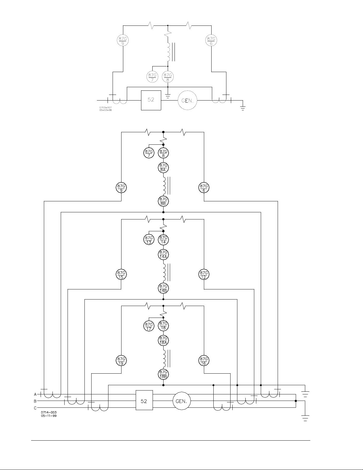
Figure 1-1. Typical Single-Phase Application Scheme
Figure 1-2. Typical Three-Phase Application Scheme
1-2 BE1-87G General Information 9170800990 Rev N
Page 13

Variable Restraint Characteristic
At high current levels, the inevitable difference in the saturation characteristics between current
transformers indicates a need for a compensating decrease in relay sensitivity. The design of the BE187G provides a restraint factor that is proportional to input current when the restraining current (I
) is
R
greater than nominal (5 Aac for sensing input range 1 or 1 Aac for sensing input range 2). The BE1-87G
compares the protected zone sensed input and output currents. The lesser of the two sensed current
levels becomes the restraining current. The difference between the two sensed currents (the operating
current) is compared to a reference established by the sensitivity setting, and adjusted by an amount
proportional to the restraining current. This makes the BE1-87G more sensitive to low current internal
faults, and less sensitive to external faults with high levels of through current.
When the restraining current is at nominal (5 Aac for sensing input range 1 or 1 Aac for sensing input
range 2) or less, the relay trips if the differential current exceeds the relay setting (I
). But when the
S
restraining current is greater than nominal, the overall sensitivity is a combination of the front panel setting
and the restraint factor.
Design Highlights
Some of the many advantages of the BE1-87G relay are summarized below:
• Seven sensitivity levels on each of the two sensing input ranges. The seven levels allow
compensation for CT mismatch and provide the flexibility and adaptability necessary for many special
applications such as split-winding generator protection.
• Stabilizing reactor. Minimizes dissimilar performance of system CTs. Reactor can be located on the
back of the relay or remotely from the BE1-87G for flexibility of system installation.
• Variable restraint. The variable restraint characteristic allows increased sensitivity to low-current,
internal faults while providing increased security against high levels of through-current caused by
external faults.
• Single- or three-phase availability. Either configuration is available in the Basler Electric S1 draw-out
case.
• High-speed operation. The BE1-87G operates in 30 milliseconds for fault levels of 10 times the
sensitivity setting. This high-speed operation minimizes potential damage to the protected equipment.
Response characteristics for sensing input ranges 1 and 2 are shown in Section 5, Testing and
Setting.
MODEL AND STYLE NUMBER
The model number BE1-87G designates the relay as a Basler Electric, Class 100, Variable Percentage
Differential Relay.
The electrical characteristics and operational features of the BE1-87G relay are defined by a combination
of letters and numbers which constitutes the relay style number. The style number describes the features
and options of the BE1-87G relay and appears on the front panel, draw-out cradle, and inside the case
assembly.
Style Number Chart
The BE1-87G style number chart is illustrated in Figure 1-3.
Style Number Example
As an example, if the style number of a BE1-87G were G1EA1JA0C0F, the relay would have the
following characteristics and features:
G three-phase current sensing
1 switch-selectable sensing input range for 0.1, 0.15, 0.2, 0.4, 0.5, 0.8, or 1.6 Aac
E one normally-open output relay
A1 instantaneous timing
J relay operating power derived from 125 Vdc or 100/120 Vac
A internally operated targets (one per phase)
0 option 1 not available
C push-to-energize outputs (pushbuttons)
0 no auxiliary output contacts
F semi-flush mounting case
9170800990 Rev N BE1-87G General Information 1-3
Page 14
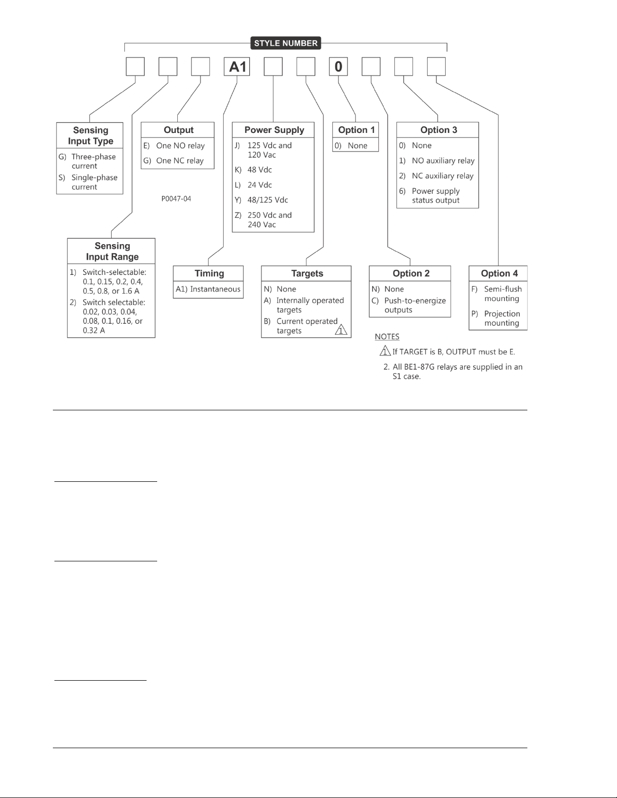
Figure 1-3. Style Number Identification Chart
SPECIFICATIONS
BE1-87G relays have the following features and capabilities.
Current Sensing Inputs
Sensing Input Range 1
Nominal Rating: 5 Aac
Maximum Continuous Rating: 10 Aac
1 Second Rating: 250 Aac
Frequency Range: 45 to 65 Hz
Burden: <0.05 Ω per input
Sensing Input Range 2
Nominal Rating: 1 Aac
Maximum Continuous Rating: 2 Aac
1 Second Rating: 50 Aac
Frequency Range: 45 to 65 Hz
Burden: <0.25 Ω per input
Stabilizer Reactor
Refer to Section 3, Functional Description for stabilizer reactor impedance characteristic curves.
I2t Rating (I2t = 4225)
Sensing Input Range 1: 65 A for 1 s at 70°C ambient
Sensing Input Range 2: 13 A for 1 s at 70°C ambient
1-4 BE1-87G General Information 9170800990 Rev N
Page 15
Pickup
Type
Input Voltage
Burden at Nominal
Nominal
Range
K (midrange)
48 Vdc
24 to 150 Vdc
2.75 W
J (midrange)
125 Vdc
120 Vac
24 to 150 Vdc
90 to 132 Vac
2.96 W
7.87 VA
L (low range)
24 Vdc
∗ 12 to 32 Vdc
2.85 W
Y (mid range)
48 Vdc
125 Vdc
24 to 150 Vdc
24 to 150 Vdc
2.75 W
2.96 W
Z (high range)
250 Vdc
230 Vac
68 to 280 Vdc
90 to 270 Vac
3.13 W
9.20 VA
Graphs of the actual operating characteristics are shown in Section 5, Testing and Setting.
Control
A front panel sensitivity switch permits selection of minimum differential (operate) current. This sensitivity
is constant for restraint currents less than the nominal current (5 Aac for sensing input range 1 or 1 Aac
for sensing input range 2).
Minimum Differential (Operate) Current
Sensing Input Range 1: 0.1, 0.15, 0.2, 0.4, 0.5, 0.8, or 1.6 A
Sensing Input Range 2: 0.02, 0.03, 0.04, 0.08, 0.10, 0.16, or 0.32 A
The ideal operating characteristic is approximated by the following equations∗:
Sensing Input Range 1: For I
For I
Sensing Input Range 2: For I
For I
is the restraint current, defined as the lesser of the input currents
∗ I
R
is the operate current
I
OP
is the front panel setting
I
S
≤ 5 A: IOP = IS
R
> 5 A: IOP = IS + 0.5 (IR − 5)
R
≤ 1 A: IOP = IS
R
> 1 A: IOP = IS + 0.5 (IR − 1)
R
Accuracy
Sensing Input Range 1
For I
≤ 4 A: ±5% of the operate pickup characteristic or ±25 mA, whichever is
R
greater
For I
> 6 A (20 A max.): ±8% of the operate pickup characteristic or ±150 mA, whichever is
R
greater
Sensing Input Range 2
For I
≤ 0.8 A: ±5% of the operate pickup characteristic or ±25 mA, whichever is
R
greater
For I
> 1.2 A (4 A max.): ±8% of the operate pickup characteristic or ±150 mA, whichever is
R
greater
Dropout
>90% of operate characteristic
Timing
<30 ms at 10 times pickup setting, 70 ms maximum
Operating Power Input
Relay operating power may be obtained from a wide variety of external voltage sources. When ordering,
any one of five internal power supply types may be selected to match the operating power voltage level
available at your site. Available power supply types are listed in Table 1-1.
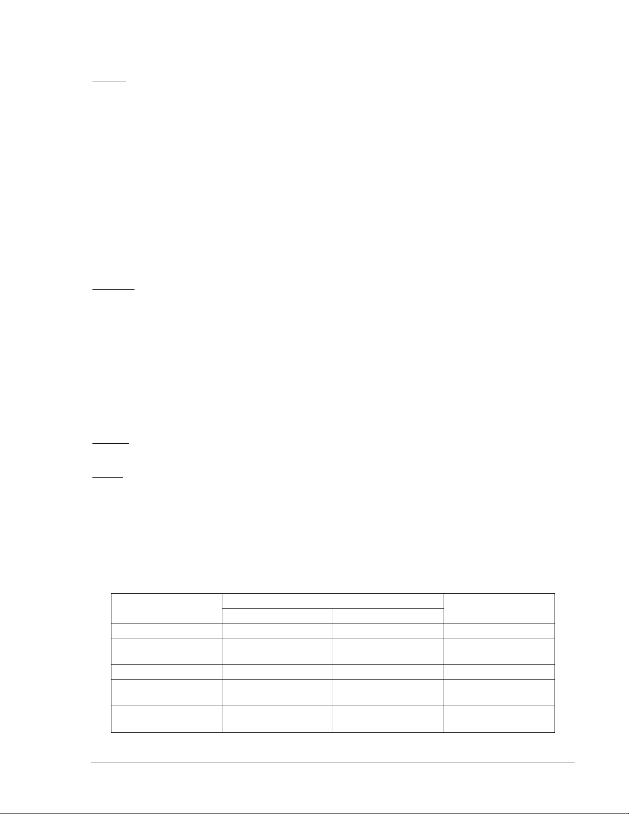
Table 1-1. Power Supply Types
9170800990 Rev N BE1-87G General Information 1-5
∗ The type L power supply initially requires 14 Vdc to begin operating. Once operating, the
voltage may be reduced to 12 Vdc and operation will continue.
Page 16

Output Contacts
Resistive Ratings
120 Vac: Make, break, and carry 7 Aac continuously
250 Vdc: Make and carry 30 Adc for 0.2 s, carry 7 Adc continuously,
break 0.3 Adc
500 Vdc: Make and carry 15 Adc for 0.2 s, carry 7 Adc continuously,
break 0.3 Adc
Inductive Ratings
120 Vac, 125 Vdc, 250 Vdc: Break 0.3 A (L/R = 0.04)
Targets
Electronically latched, manually reset target indicators may be optionally selected as either internally
operated or current operated.
Current operated targets require a minimum trip circuit current of 200 milliamperes and have a continuous
rating of 3 amperes, a two-minute rating of 7 amperes, and a one-second rating of 30 amperes.
Internally operated targets should be selected if the relay has normally-closed output contacts.
Type Tests
Dielectric Strength
In accordance with ANSI/IEEE C37.90, passes one-minute dielectric tests as follows:
All Circuits to Ground: 2,121 Vdc
Input Circuits to Output Circuits: 1,500 Vac or 2,121 Vdc
Surge Withstand Capability
Qualified to ANSI/IEEE C37.90.1-1989
Fast Transient Immunity
Qualified to ANSI/IEEE C37.90.1-1989
Impulse Testing
Qualified to IEC 255-5
Radio Frequency Interference
Maintains proper operation when tested for interference in accordance with IEEE C37.90.2
Shock
Withstands 15 G in each of three mutually perpendicular planes.
Vibration
Withstands 2 G in each of three mutually perpendicular planes, swept over the range of 10 to 500 Hz for a
total of six sweeps, 15 minutes each sweep.
Physical
Temperature
Operating: –40 to 70°C (–40 to 158°F)
Storage: –65 to 100°C (–85 to 212°F)
Weight
Single-Phase Sensing Units: 14.3 lb (6.5 kg) maximum
Three-Phase Sensing Units: 19.2 lb (8.7 kg) maximum
Case Size
All units are supplied in an S1 case size. See Section 4, Installation for case dimensions.
1-6 BE1-87G General Information 9170800990 Rev N
Page 17

Agency Recognition
UL Recognition: UL recognized per Standard 508, File E97033
NOTE: Output contacts are not UL recognized for voltages greater
than 250 volts.
GOST-R Certification
GOST-R certified per the relevant standards of Gosstandart of Russia.
9170800990 Rev N BE1-87G General Information 1-7
Page 18

This page intentionally left blank.
1-8 BE1-87G General Information 9170800990 Rev N
Page 19

SECTION 2 • CONTROLS AND INDICATORS
TABLE OF CONTENTS
SECTION 2 • CONTROLS AND INDICATORS ........................................................................................ 2-1
GENERAL .............................................................................................................................................. 2-1
Figures
Figure 2-1. Controls and Indicators ........................................................................................................... 2-1
Tables
Table 2-1. Control and Indicator Descriptions ........................................................................................... 2-1
9170800990 Rev N BE1-87G Controls and Indicators i
Page 20

This page intentionally left blank.
ii BE1-87G Controls and Indicators 9170800990 Rev N
Page 21
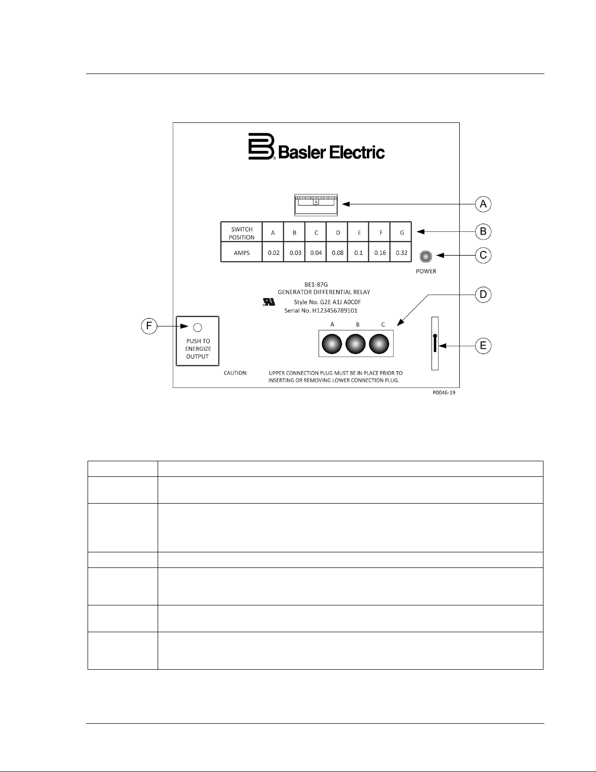
SECTION 2 • CONTROLS AND INDICATORS
Locator
Description
A
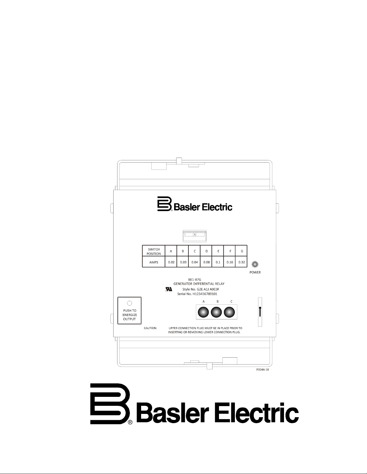
Sensitivity Switch. This thumbwheel switch has seven positions labeled A through G
and sets the desired level of operating current that will cause the relay to trip.
B
Switch Position Chart. This chart relates the switch position to the operating current
range 2).
C
Power Indicator. This LED lights when operating power is applied to the relay.
D
Target Indicators. Electronically-latching red target LEDs light when a trip condition
a target LED is provided for each phase protected.
E
Target Reset Switch. Operating this switch resets all of the target indicators (locator
D).
F
Output Test Switch. This momentary-action pushbutton switch operates the output and
through the access hole in the front panel.
GENERAL
BE1-87G controls and indicators are illustrated in Figure 2-1 and described in Table 2-1.
Figure 2-1. Controls and Indicators
Table 2-1. Control and Indicator Descriptions
required for tripping when the restraint current is less than or equal to the nominal
value of sensing current (5 Aac for sensing input range 1 or 1 Aac for sensing input
exists on the corresponding phase of current. When the optional targets are specified,
auxiliary relays. The switch is accessed by inserting a ⅛” diameter, non-conducting rod
9170800990 Rev N BE1-87G Controls and Indicators 2-1
Page 22

This page intentionally left blank.
2-2 BE1-87G Controls and Indicators 9170800990 Rev N
Page 23

SECTION 3 • FUNCTIONAL DESCRIPTION
TABLE OF CONTENTS
SECTION 3 • FUNCTIONAL DESCRIPTION ........................................................................................... 3-1
INTRODUCTION ................................................................................................................................... 3-1
BE1-87G FUNCTION BLOCKS ............................................................................................................. 3-1
Current Sensing Inputs ....................................................................................................................... 3-1
Stabilizing Reactor ............................................................................................................................. 3-1
Band-Pass Filters ............................................................................................................................... 3-2
Comparator ........................................................................................................................................ 3-3
Output Relays ..................................................................................................................................... 3-3
Target Indicators (Optional)................................................................................................................ 3-3
Output Test Pushbutton ..................................................................................................................... 3-4
Power Supply ..................................................................................................................................... 3-4
Figures
Figure 3-1. Function Block Diagram .......................................................................................................... 3-1
Figure 3-2. Stabilizing Reactor Impedance Characteristic, Sensing Input Range 1 ................................. 3-2
Figure 3-3. Stabilizing Reactor Impedance Characteristic, Sensing Input Range 2 ................................. 3-2
9170800990 Rev N BE1-87G Functional Description i
Page 24

This page intentionally left blank.
ii BE1-87G Functional Description 9170800990 Rev N
Page 25

SECTION 3 • FUNCTIONAL DESCRIPTION
INTRODUCTION
This section describes how the BE1-87G functions and explains its operating features.
BE1-87G FUNCTION BLOCKS
BE1-87G function blocks are illustrated in Figure 3-1 and described in the following paragraphs.
Figure 3-1. Function Block Diagram
Current Sensing Inputs
Sensing current for each monitored phase is provided by two user-provided, system CTs with secondary
windings that match the BE1-87G’s sensing input range. BE1-87G relays with sensing input range 1 (style
x1x-xxx-xxxx) require CTs with 5 Aac secondary windings. Relays with sensing input range 2 (style x2xxxx-xxxx) require CTs with 1 Aac secondary windings. Two CTs are used on each phase—one CT on
each side of the protected machine. Sensing current is applied to internal transformers that provide
system isolation and determine the differential and sum currents. These CTs are gapped to withstand dc
offset.
Stabilizing Reactor
To minimize dissimilar performance of the system CTs, the stabilizing reactor acts as a stabilizing
impedances during external faults. Stabilizing reactors are current rated based on time and ambient
temperature (refer to Section 1, General Information, Specifications). Figures 3-2 and 3-3 illustrate the
stabilizing reactor impedance characteristic.
9170800990 Rev N BE1-87G Functional Description 3-1
Page 26

Figure 3-2. Stabilizing Reactor Impedance Characteristic, Sensing Input Range 1
Figure 3-3. Stabilizing Reactor Impedance Characteristic, Sensing Input Range 2
Band-Pass Filters
The outputs of the relay’s internal transformers are filtered to eliminate the third harmonic and minimize
the effect of dc offset caused by CT saturation (as may occur during synchronization or asymmetrical
faults). Two band-pass filters are used: difference and sum.
The output of the difference band-pass filter is applied to a full-wave rectifier. The rectifier scales the
differential and applies the output to the comparator as the operating current (I
) signal.
OP
The output of the sum band-pass filter is also applied to a full-wave rectifier. The scaled sum of the two
inputs represents the restraint current (I
). The restraint current is scaled for a 50% slope above nominal
R
input current (5 Aac for sensing input range 1 or 1 Aac for sensing input range 2).
3-2 BE1-87G Functional Description 9170800990 Rev N
Page 27

Comparator
The comparator provides the variable percentage characteristic of the relay as follows.
Restraint Current Less than Nominal
When IR is less than nominal (5 Aac for sensing input range 1 or 1 Aac for sensing input range 2), the
comparator provides an output signal whenever I
exceeds the front panel sensitivity setting.
OP
Restraint Current Greater than Nominal
When IR is greater than nominal (5 Aac for sensing input range 1 or 1 Aac for sensing input range 2), the
front panel sensitivity switch setting (threshold) is increased by adding it to a scaled value representing
one half of I
minus nominal (5 Aac for sensing input range 1 or 1 Aac for sensing input range 2).
R
Output Relays
When the current difference exceeds the variable percentage limit (sensitivity switch setting), the
comparator output energizes the output relays. (In BE1-87G models with three-phase sensing, the
outputs are ORed together so that the output relays energize if the current difference of any one phase
exceeds the limit.) When the current difference decreases below 90% of the variable percentage
threshold, the output relays reset.
Main Output Relay
The main output relay contacts are either normally-open or normally-closed and are accessed at case
terminals 1 and 10. Normally-open contacts are provided on BE1-87G relays with a style number of xxExxx-xxxxx and normally-closed contacts are provided on relays with a style number of xxG-xxx-xxxxx.
Auxiliary Output Relay (Optional)
An optional pair of contacts, accessed at case terminals 2 and 5, can be specified. The auxiliary output
contacts change state when the main output contacts operate and are available in a normally-open or
normally-closed configuration. Normally-open auxiliary contacts are provided on BE1-87G relays with
style number xxx-xxx-xxx1x and normally-closed auxiliary contacts are provided on relays with style xxxxxx-xxx2x.
Optionally, the auxiliary output relay can be specified to function as a power supply status output. This
normally-closed output is energized open during normal operation. When relay control power is lost or an
internal power supply failure occurs, the relay de-energizes and closes the contacts at terminals 2 and 5.
Target Indicators (Optional)
Target indicators are optional components selected when a relay is ordered. The electronically latched
and reset targets consist of red LED indicators located on the relay front panel. Latched targets are reset
by operating the target reset switch on the front panel. If relay operating power is lost, any illuminated
(latched) targets are extinguished. When relay operating power is restored, the previously latched targets
are restored to their latched state.
A relay can be equipped with either internally operated targets or current operated targets. Both target
types are reset by operating the target reset switch.
Internally Operated Targets
The relay trip outputs are directly applied to drive the target indicators. The indicators are illuminated
regardless of the current level in the trip circuits.
Current Operated Targets
Current operated targets are triggered by closure of the corresponding output contact and the presence of
at least 200 milliamperes of current flowing in the trip circuit.
NOTE
Prior to September 2007, the BE1-87G target indicators consisted of
magnetically latched, disc indicators. These mechanically latched target
indicators have been replaced by the electronically latched LED targets in use
today.
9170800990 Rev N BE1-87G Functional Description 3-3
Page 28

Output Test Pushbutton
A relay with style number xxx-xxx-xxCxx is equipped with a momentary-action pushbutton accessible
through the front panel. When pressed, the switch energizes the main and auxiliary output relays. To
prevent accidental relay tripping, the pushbutton is recessed behind the front panel. The button is pressed
by insertion of a thin, non-conducting rod through the button access hole in the front panel.
Power Supply
Relay operating power is developed by a wide-range, isolated, low-burden, switching power supply that
delivers ±12 Vdc to the relay’s internal circuitry. The power supply is not sensitive to the input power
polarity. A front panel LED power indicator lights to indicate that the power supply is functioning properly.
Style number designations and input voltage ranges for the available power supply models are provided
in Section 1, General Information.
3-4 BE1-87G Functional Description 9170800990 Rev N
Page 29

SECTION 4 • INSTALLATION
TABLE OF CONTENTS
SECTION 4 • INSTALLATION .................................................................................................................. 4-1
INTRODUCTION ................................................................................................................................... 4-1
MOUNTING............................................................................................................................................ 4-1
Stabilizing Reactor ........................................................................................................................... 4-14
CONNECTIONS .................................................................................................................................. 4-16
Internal Connections ........................................................................................................................ 4-16
Control Connections ......................................................................................................................... 4-16
Sensing Connections ....................................................................................................................... 4-16
MAINTENANCE ................................................................................................................................... 4-23
STORAGE............................................................................................................................................ 4-23
Figures
Figure 4-1. Panel Cutting/Drilling, Semi-Flush, S1 Case .......................................................................... 4-2
Figure 4-2. S1 Case Dimensions, Rear View, Double Ended, Semi-Flush Mount ................................... 4-3
Figure 4-3. S1 Case Dimensions, Side View, Double Ended, Semi-flush Mount ..................................... 4-4
Figure 4-4. S1 Case Dimensions, Rear View, Single Ended, Semi-Flush Mount ..................................... 4-5
Figure 4-5. S1 Case Dimensions, Side View, Single Ended, Semi-Flush Mount ..................................... 4-6
Figure 4-6. Panel Cutting/Drilling, Double Ended, Projection Mount, S1 Case ........................................ 4-7
Figure 4-7. S1 Case Dimensions, Rear View, Double Ended, Projection Mount ...................................... 4-8
Figure 4-8. S1 Case Dimensions, Side View, Double Ended, Projection Mount ...................................... 4-9
Figure 4-9. Panel Cutting/Drilling, Single Ended, Projection Mount, S1 Case ........................................ 4-10
Figure 4-10. S1 Case Dimensions, Rear View, Single Ended, Projection Mount ................................... 4-11
Figure 4-11. S1 Case Dimensions, Side View, Single Ended, Projection Mount .................................... 4-12
Figure 4-12. S1 Case Cover Dimensions, Front View............................................................................. 4-13
Figure 4-13. Overall Dimensions, Stabilizing Reactor ............................................................................. 4-15
Figure 4-14. Outline Dimensions, Side View, Semi-Flush Mounted Case with Attached Stabilizing
Reactor .................................................................................................................................................... 4-15
Figure 4-15. Internal Connections/Terminal Assignments, Single-Phase Relay .................................... 4-17
Figure 4-16. Internal Connections/Terminal Assignments, Three-Phase Relay ..................................... 4-18
Figure 4-17. Typical DC Control Connections ......................................................................................... 4-19
Figure 4-18. Single-Phase Sensing Connections .................................................................................... 4-20
Figure 4-19. Three-Phase Sensing Connections, Wye Connected Generator ....................................... 4-21
Figure 4-20. Three-Phase Sensing Connections, Delta Connected Generator ...................................... 4-22
9170800990 Rev N BE1-87G Installation i
Page 30

This page intentionally left blank.
ii BE1-87G Installation 9170800990 Rev N
Page 31

SECTION 4 • INSTALLATION
INTRODUCTION
Upon receipt of a relay, check the model and style number against the requisition and packing list to
ensure that they agree.
If there is any evidence of shipping damage, file a claim with the carrier and notify Basler Electric.
If the relay won’t be installed immediately, store it in its original shipping carton in a moisture- and dustfree environment.
MOUNTING
Because the relay is of solid-state design, it does not have to be mounted vertically. Any convenient
mounting angle may be chosen. Relay outline dimensions and panel drilling diagrams are illustrated in
Figures 4-1 through 4-12
9170800990 Rev N BE1-87G Installation 4-1
Page 32

3.03 (77)
6.06 (154)
0.25 (6) diameter, 4 places
C
L
Cut-Out
0.575
(15)
8.63
(219)
0.552
(14)
5.69 (144)
Outer Edge of Cover
0.480
(12)
8.25
(210)
4.13
(105)
0.480
(12)
P0072-12
Figure 4-1. Panel Cutting/Drilling, Semi-Flush, S1 Case
4-2 BE1-87G Installation 9170800990 Rev N
Page 33

Figure 4-2. S1 Case Dimensions, Rear View, Double Ended, Semi-Flush Mount
9170800990 Rev N BE1-87G Installation 4-3
Page 34

.75
(19.1)
(157.2)
6.19
(49.53)
1.95
10-32 SCREWS
(7.9)
.31
10-32 SCREWS
(102.4)
4.03
4.03
(102.4)
(7.9)
.31
MOUNTING PANEL
(55.75)
2.195
P0066-64
Figure 4-3. S1 Case Dimensions, Side View, Double Ended, Semi-flush Mount
4-4 BE1-87G Installation 9170800990 Rev N
Page 35

Figure 4-4. S1 Case Dimensions, Rear View, Single Ended, Semi-Flush Mount
9170800990 Rev N BE1-87G Installation 4-5
Page 36

.75
(19.1)
(157.2)
6.19
(49.53)
1.95
10-32 SCREWS
MOUNTING PANEL
(55.75)
2.195
P0066-69
8.06
(204.72)
(7.9)
.31
Figure 4-5. S1 Case Dimensions, Side View, Single Ended, Semi-Flush Mount
4-6 BE1-87G Installation 9170800990 Rev N
Page 37

Figure 4-6. Panel Cutting/Drilling, Double Ended, Projection Mount, S1 Case
9170800990 Rev N BE1-87G Installation 4-7
Page 38

Figure 4-7. S1 Case Dimensions, Rear View, Double Ended, Projection Mount
4-8 BE1-87G Installation 9170800990 Rev N
Page 39

.75
(19.1)
(157.2)
6.19
(49.53)
1.95
10-32 SCREWS
(7.9)
.31
10-32 SCREWS
(102.4)
4.03
4.03
(102.4)
(7.9)
.31
(55.75)
2.195
P0066-67
TERMINAL EXTENSION (TYP.)
FOR DETAILED INSTRUCTIONS,
SEE THE TERMINAL PROJECTION
MOUNTING KIT SUPPLIED.
.25
(6.4)
5/16-18 STUD
2 PLACES
MOUNTING PANEL
Figure 4-8. S1 Case Dimensions, Side View, Double Ended, Projection Mount
9170800990 Rev N BE1-87G Installation 4-9
Page 40

Figure 4-9. Panel Cutting/Drilling, Single Ended, Projection Mount, S1 Case
4-10 BE1-87G Installation 9170800990 Rev N
Page 41

Figure 4-10. S1 Case Dimensions, Rear View, Single Ended, Projection Mount
9170800990 Rev N BE1-87G Installation 4-11
Page 42

(157.2)
6.19
(49.53)
1.95
10-32 SCREWS
MOUNTING PANEL
(55.75)
2.195
P0066-71
TERMINAL EXTENSION (TYP.)
FOR DETAILED INSTRUCTIONS,
SEE THE TERMINAL PROJECTION
MOUNTING KIT SUPPLIED.
.25
(6.4)
5/16-18 STUD
2 PLACES
MOUNTING PANEL
8.06
(204.72)
(7.9)
.31
.75
(19.1)
Figure 4-11. S1 Case Dimensions, Side View, Single Ended, Projection Mount
4-12 BE1-87G Installation 9170800990 Rev N
Page 43

P0066-68
Figure 4-12. S1 Case Cover Dimensions, Front View
9170800990 Rev N BE1-87G Installation 4-13
Page 44

Stabilizing Reactor
For three-phase relays, the stabilizing reactor consists of a module attached to the rear of the mounting
case. For projection mounting or convenience, the stabilizing reactor module can be removed and
relocated. To remove the stabilizing reactor, remove the four screws that secure the module to the
mounting plate. The mounting plate is separated from the case by removing the two hex-head bolts.
When the stabilizing reactor is relocated, it should be rewired in accordance with the connection diagrams
shown later in this section.
The overall dimensions of the stabilizing reactor are shown in Figure 4-13. A side view showing the
dimensions of a semi-flush mounting case with attached stabilizing reactor is provided in Figure 4-14.
4-14 BE1-87G Installation 9170800990 Rev N
Page 45

Figure 4-13. Overall Dimensions, Stabilizing Reactor
Figure 4-14. Outline Dimensions, Side View,
Semi-Flush Mounted Case with Attached Stabilizing Reactor
9170800990 Rev N BE1-87G Installation 4-15
Page 46

CONNECTIONS
Verify the relay model and style number before connecting and energizing the relay. Incorrect wiring may
result in damage to the relay. Except where otherwise noted, connections should be made with minimum
wire size of 14 AWG.
Internal Connections
Internal connections/terminal assignments for a single-phase relay are illustrated in Figure 4-15. Internal
connections/terminal assignments for a three-phase relay are illustrated in Figure 4-16. These figures
may show options that may not apply to your relay.
Control Connections
Typical dc control connections are shown in Figure 4-17.
Sensing Connections
Typical sensing current connections for a single-phase application are shown in Figure 4-18.
Three-phase sensing current connections are illustrated in Figure 4-19 and Figure 4-20. Figure 4-19
shows the sensing inputs connected in a wye configuration. Figure 4-20 shows the sensing inputs
connected in a delta configuration.
4-16 BE1-87G Installation 9170800990 Rev N
Page 47

Figure 4-15. Internal Connections/Terminal Assignments, Single-Phase Relay
9170800990 Rev N BE1-87G Installation 4-17
Page 48

Figure 4-16. Internal Connections/Terminal Assignments, Three-Phase Relay
4-18 BE1-87G Installation 9170800990 Rev N
Page 49

Figure 4-17. Typical DC Control Connections
9170800990 Rev N BE1-87G Installation 4-19
Page 50

Figure 4-18. Single-Phase Sensing Connections
4-20 BE1-87G Installation 9170800990 Rev N
Page 51

Figure 4-19. Three-Phase Sensing Connections, Wye Connected Generator
9170800990 Rev N BE1-87G Installation 4-21
Page 52

Figure 4-20. Three-Phase Sensing Connections, Delta Connected Generator
4-22 BE1-87G Installation 9170800990 Rev N
Page 53

MAINTENANCE
BE1-87G relays require no preventive maintenance other than the periodic inspection of the relay case
and stabilizing reactor terminal connections to ensure that they are clean and tight. If repairs are needed,
contact the Technical Sales Support department at Basler Electric for assistance.
STORAGE
This device contains long-life electrolytic capacitors. For devices that are not in service (spares in
storage), the life of these capacitors can be maximized by energizing the device for 30 minutes once per
year.
9170800990 Rev N BE1-87G Installation 4-23
Page 54

This page intentionally left blank.
4-24 BE1-87G Installation 9170800990 Rev N
Page 55

SECTION 5 • TESTING AND SETTING
TABLE OF CONTENTS
SECTION 5 • TESTING AND SETTING ................................................................................................... 5-1
INTRODUCTION ................................................................................................................................... 5-1
Relay Operating Precautions ............................................................................................................. 5-1
OPERATIONAL TEST PROCEDURE ................................................................................................... 5-1
Equipment Required ........................................................................................................................... 5-2
Single-Phase/A-Phase Trip and Dropout Test ................................................................................... 5-2
B-Phase and C-Phase Trip and Dropout Test ................................................................................... 5-3
Target Indicator Test .......................................................................................................................... 5-7
Auxiliary Output Test .......................................................................................................................... 5-7
Power Supply Status Output Test ...................................................................................................... 5-7
Push-to-Energize Output Test ............................................................................................................ 5-7
SETTING THE RELAY .......................................................................................................................... 5-7
Terms for Calculations ....................................................................................................................... 5-7
CT Quality .......................................................................................................................................... 5-8
Burden Limit ....................................................................................................................................... 5-8
Relative CT Performance ................................................................................................................... 5-8
Setting Example 1 .............................................................................................................................. 5-8
Setting Example 2 .............................................................................................................................. 5-9
Figures
Figure 5-1. Location of Stabilizing Reactor Bypass Terminals (Single-Phase Relays) ............................. 5-2
Figure 5-2. Operational Test Setup ........................................................................................................... 5-3
Figure 5-3. Operating Characteristics, Relay Style x1x-xxx-xxxxx ............................................................ 5-4
Figure 5-4. Operating Characteristics, Relay Style x2x-xxx-xxxxx ............................................................ 5-5
Figure 5-5. Extended Restraint Operating Characteristic.......................................................................... 5-6
Figure 5-6. Pickup Response Timing ........................................................................................................ 5-6
Figure 5-7. Motor Differential Application .................................................................................................. 5-9
Figure 5-8. Generator Differential Application ......................................................................................... 5-10
Tables
Table 5-1. Recommended Pickup Settings ............................................................................................... 5-8
9170800990 Rev N BE1-87G Testing and Setting i
Page 56

This page intentionally left blank.
ii BE1-87G Testing and Setting 9170800990 Rev N
Page 57

SECTION 5 • TESTING AND SETTING
INTRODUCTION
Proper relay operation can be confirmed by performing the test procedures in this section. This section
also contains recommendations for selecting an appropriate sensitivity switch (operating current) setting.
Relay Operating Precautions
Before operating the relay, note the following precautions:
CAUTION
To avoid false tripping on three-phase relays, the upper connection plug must be
in place prior to inserting or removing the lower connection plug.
• A minimum of 200 mA in the output circuit is required to ensure operation of current operated targets
(relays with style number xxx-xxB-xxxxx)
• If a wiring insulation test is required, remove the connection plugs and withdraw the cradle from its
case
• When the connection plugs are removed, the relay is disconnected from the operating circuit and will
not provide system protection. Before removing a relay from service, be sure that external operating
(monitored) conditions are stable.
• The relay case must be hard-wired to earth ground with no smaller than 12 AWG copper wire. A
separate ground lead is recommended for each device.
OPERATIONAL TEST PROCEDURE
The procedures that follow verify proper operation of the BE1-87G relay
CAUTION
During testing, do not apply a continuous operate current greater than 3 Aac.
Sustained operate current higher than 3 Aac will increase the temperature in the
stabilizing reactor and cause insulation breakdown.
NOTE
Because of the reactance of the stabilizing reactors, the burden may be too high
for large values of operate current with solid-state test sets.
The internal stabilizing reactor in relays with single-phase sensing (style number
Sxx-xxx-xxxxx) may be bypassed by placing a jumper across the terminals
illustrated in Figure 5-1. The jumper used should be capable of carrying 5 Aac of
current.
To bypass the external stabilizing reactor used on relays with three-phase
sensing (style number Gxx-xxx-xxxxx), the current source may be connected
directly to the relay case terminals
Restraint current applied to any one relay input must not exceed either of the following conditions:
• 10 amperes continuous or 250 amperes for 1 second (relay style number x1x-xxx-xxxxx)
• 2 amperes continuous or 50 amperes for 1 second (relay style number x2x-xxx-xxxxx)
Whenever this current level is exceeded, provisions must be made to cut off the sensing current as the
relay trips.
9170800990 Rev N BE1-87G Testing and Setting 5-1
Page 58

Figure 5-1. Location of Stabilizing Reactor Bypass Terminals (Single-Phase Relays)
Equipment Required
Because of the speed and sensitivity of the BE1-87G, test equipment with appropriate accuracy and
stability must be used to test the sensitivity switch settings. For example, at the most sensitive switch
setting (0.1 ampere), the relay monitors a current difference that is only 1% for a sensing input of 10
amperes.
• Two adjustable current sources (Doble, AVO, or equivalent equipment)
• Digital voltmeter (±1% accuracy or better)
• Digital ammeter (±1% accuracy or better)
• Variable, 0 to 250 Vac/Vdc power supply (for relay operating power)
• DC power supply (for current operated targets)
Single-Phase/A-Phase Trip and Dropout Test
Perform the following steps to test the trip and dropout accuracy of relays with single-phase sensing (style
number Sxx-xxx-xxxxx) or phase A of relays with three-phase sensing (style number Gxx-xxx-xxxxx).
1. Connect the test setup shown in Figure 5-2. Current sensing connections should be made at
terminals 6, 7, 8, and 9.
2. Set the sensitivity switch at position A.
3. Apply the appropriate voltage to relay operating power terminals 3 and 4. (A power supply
model/input voltage cross-reference is provided in Table 1-1.)
4. Using a regulated, independently adjustable current source, apply the restraint current to relay
terminals 6 and 9. A current value of 0.1 Aac is applied for relays with style number x1x-xxx-xxxxx
and a current value of 0.02 Aac is applied for relays with style number x2x-xxx-xxxxx.
5-2 BE1-87G Testing and Setting 9170800990 Rev N
Page 59

5. Slowly increase the operate current applied to terminals 6 and 8 until the relay trips. A relay with a
style number of x1x-xxx-xxxxx should trip at 0.1 Aac and a relay with a style number of x2x-xxx-xxxxx
should trip at 0.02 Aac. Tolerance is ±5% or 25 mA, whichever is greater.
NOTE
Depending upon the relay style number, the relay may be equipped with
normally-open or normally-closed trip contacts. Check continuity at terminals 1
and 10 with the relay tripped and not tripped to verify correct response for the
type of contacts specified.
6. Slowly decrease the operate current source until dropout occurs. Dropout should occur at a current
value that is greater than or equal to 90% of I
(the sensitivity switch setting value).
S
7. Repeat steps 2 through 6 for the other sensitivity switch settings. If desired, a sufficient number of trip
points may be taken to verify any or all of the performance curves shown in Figure 5-3.
For restraint current (I
≤ 1 ampere for style number x2x-xxx-xxxxx), the tolerance is ±0.05 • IOP or 25 mA, whichever is
or I
R
) less than or equal to nominal (IR ≤ 5 amperes for style number x1x-xxx-xxxxx
R
greater.
> nominal (up to a maximum of 20 amperes for style number x1x-xxx-xxxxx or 4 amperes for
For I
R
style number x2x-xxx-xxxxx), the tolerance is ±0.08 • I
on the characteristic curve or 150 mA,
OP
whichever is greater.
See Figures 5-3 through 5-6 for the operating characteristic curves and trip response timing curve.
Figure 5-2. Operational Test Setup
B-Phase and C-Phase Trip and Dropout Test
Perform the following steps to test the trip and dropout accuracy of phases B and C of relays with threephase sensing (style number Gxx-xxx-xxxxx).
Perform steps 1 through 7 under Single-Phase/A-Phase Trip and Dropout Test for phases B and C.
9170800990 Rev N BE1-87G Testing and Setting 5-3
Page 60

Figure 5-3. Operating Characteristics, Relay Style x1x-xxx-xxxxx
5-4 BE1-87G Testing and Setting 9170800990 Rev N
Page 61

Figure 5-4. Operating Characteristics, Relay Style x2x-xxx-xxxxx
9170800990 Rev N BE1-87G Testing and Setting 5-5
Page 62

RESTRAINT CURRENT (AMPERES)
OPERATING CURRENT (AMPERES)
0
2
4
8
6
10
12
14
16
18
20
0
5 10 15 20 25 30 35 40
0
1 2 3 4 5 6 7 8
D2354-14
Range 1
Range 2
Figure 5-5. Extended Restraint Operating Characteristic
5-6 BE1-87G Testing and Setting 9170800990 Rev N
Figure 5-6. Trip Response Timing
Page 63

Target Indicator Test
If the relay is equipped with target indicators, verify proper operation of each phase when the relay is
tripped. Verify that the targets reset when the target reset switch is operated during a non-tripped
condition.
NOTE
Relays with a style number of xxx-xxB-xxxxx have current operated targets.
These targets will operate only when a minimum of 200 mA is flowing in the trip
output circuit (terminals 1 and 10).
Auxiliary Output Test
Check output contact operation at terminals 2 and 5 of relays equipped with auxiliary output contacts.
Relays with style number xxx-xxx-xxx1x have normally-open auxiliary contacts. These contacts close
when the relay trips.
Relays with style number xxx-xxx-xxx2x have normally-closed auxiliary contacts. These contacts open
when the relay trips.
Power Supply Status Output Test
Relays with a style number of xxx-xxx-xxx6x are equipped with a set of power supply status output
contacts.
1. Apply operating power to the relay and verify that the power supply status output contacts (terminals
2 and 5) are energized open.
2. Remove relay operating power and confirm that contact closure occurs across terminals 2 and 5.
Push-to-Energize Output Test
If an output test switch is present (relay style number xxx-xxx-xxCxx) verify operation by depressing the
switch and observing that the trip output (terminals 1 and 10) and the auxiliary output (terminals 2 and 5)
cycle.
SETTING THE RELAY
The following recommendations are provided for selecting the current sensitivity switch setting. Figures 53 and 5-4 show how this setting corresponds to the operating current pickup over the restraint current
range.
Assuming that the CTs on both sides of the zone (generator, motor, or reactor) perform identically,
operating current will be equal to zero. The sensitivity setting serves to accommodate dissimilar CT
performance, resulting from differences in CT quality, burden, and core remanence.
During normal operation, the pickup on the flat part of the operating characteristic (see Figures 5-3 and 5-
4) must exceed the difference in steady-state CT errors. The relay must also override the error
differences in the presence of dc components developed by external faults or switching. Currents will be
offset during external faults on generator applications, during motor starting, and during switching of shunt
reactors.
Out-of-phase synchronizing of machines will also produce offset components. These so-called dc
components will produce significant CT saturation. For high current faults, the relay relies on the 50%
slope characteristic to override large operating currents. Significant operating current can also be
developed at restraint levels that fall on the flat part of the characteristic if the offset component persists.
The sensitivity setting needs to be above this operating current.
Terms for Calculations
Sub-transient current
I”
d
N Total number of CT turns
Number of CT turns in use (for multi-ratio type)
N
a
One-way lead resistance in ohms
R
I
Relay restraint circuit resistance in ohms
R
r
CT winding resistance in ohms
R
w
9170800990 Rev N BE1-87G Testing and Setting 5-7
Page 64

Vce (Lower Value)
SFR
1
1.5 2 3 4 20
0.2
0.4
0.5
0.8
1.6
50
0.2
0.4
0.4
0.5
0.8
100
0.2
0.2
0.4
0.4
0.5
200
0.1
0.1
0.2
0.4
0.5
>200
0.1
0.1
0.2
0.4
0.5
NOTE
Relay Style x1x-xxx-xxxxx: if Rw is unknown, assume Rw = 0.003 × N
a
Relay Style x2x-xxx-xxxxx: if Rw is unknown, assume Rw = 0.01 × Na
Rt Total CT burden = R
= 2R
SFR Saturation factor ratio = [(Vce)
+ Rr + Rw (for phase faults and switching)
i
+ 2Rr + Rw (for external ground faults)
i
÷ (Vce)2] × [(Rt)2 ÷ (t)1] (if SFR is <1, use 1/SFR)
1
Vc CT accuracy class voltage rating
Vce Effective CT accuracy class voltage rating = Vc(N
Sub-transient reactance
X”
d
÷ N)
a
CT Quality
CTs should have an accuracy class of either C20 or better or T20 or better.
Burden Limit
The CTs should be operating below the knee point under symmetrical current conditions, that is, no ac
saturation. For a generator, ac saturation should not occur for the maximum external fault current. For a
motor, ac saturation should not occur during starting. For a shunt reactor, high current fundamentalfrequency currents will not flow unless the reactor becomes faulted.
Assuming a maximum current of 20 times the CT rating: R
< 0.007Vce, where V
t
= 70% of Vce and 20
knee
× 5 A nominal rating = 100 A so that:
= V
R
t
÷Imax = 0.7Vce ÷ 100 A = 0.007Vce
knee
Relative CT Performance
Table 5-1 lists the recommended minimum pickup settings to provide security during external faults and
switching.
Table 5-1. Recommended Pickup Settings
Note: Use next higher setting if CTs are a mix of C classification and T classification.
The saturation factor ratio, SFR, represents an index of the relative performance of the two sets of CTs.
This performance is a function of the relative quality of the CTs (Vce), the relative burdens (R
), and
t
neglecting the remanence. If SFR is less than 1, use 1/SFR for SFR.
Setting Example 1
Select the pickup setting for the motor application in Figure 5-7. In this application, the settings need to be
based on the probability of significant dissimilar CT saturation due to the very slow decaying dc
component of the starting current. Since the motor is not grounded, no ground current can flow during
starting of an unfaulted motor. Therefore, one-way lead burden is used to determine the total CT burden.
Each phase CT carries just the burden for the lead of that phase.
(R
(R
= Rl + Rw = 0.22 + 0.14 = 0.36 ; (Vce)1 = 50 ; Rt < 0.007(Vce)1 = 0.35
t)1
= 0.09 + 0.10 = 0.19 ; (Vce)2 = 100 ; Rt < 0.007(Vce)2 = 0.7
t)2
Inequality (1) is met with CT #2, but not with CT #1. However, since the locked rotor current is only 4.8
times the CT rating (versus the assumption of 20 times rated for inequality (1)), the application is suitable.
SFR = (100 ÷ 50) × (0.36 ÷ 0.19) = 3.8
5-8 BE1-87G Testing and Setting 9170800990 Rev N
Page 65

ratingCTI
d
×==
×
×
÷
= 6.
4
30
8
.138
200
15.0
)316
.4(1000
"
Figure 5-7. Motor Differential Application
Using the SFR 4 column of Table 5-1, a 0.8 ampere setting is indicated. However, based on the note
accompanying this table, choose the next higher setting of 1.6, because CT #1 has a T classification and
CT #2 has a C classification. The T classification indicates that the CT has significant secondary leakage
inductance which somewhat degrades the transient performance. This is a concern during motor starting
because a slowly decaying offset component develops in at least one phase.
Setting Example 2
Select the pickup setting for the generator application in Figure 5-8. In this application, the settings need
to be based on the probability of significant dissimilar CT saturation during an external fault. Since the
generator is resistance grounded, the three-phase fault current will be much larger than the ground fault
level. Moreover, the resistor will rapidly dampen any offset-current component. Accordingly, determine the
sub-transient current (I”
Since a three-phase fault is involved, one-way lead burden is used to determine the total CT burden.
Each phase CT carries just the burden for the lead of that phase.
(R
(R
Inequality (1) is met with CT #2 but not with CT #1. However, since the maximum external fault current is
only 4.6 time the CT rating (versus the assumption of 20 times rated for inequality (1)), the application is
suitable.
SFR = (1000 ÷ 50) × (0.36 ÷ 0.19) = 3.8
Using the SFR 4 column of Table 5-1, a 0.8 ampere setting is indicated. However, based on the note
accompanying Table 5-1, choose the next higher setting of 1.6 because CT #1 has a T classification and
CT #2 has a C classification. The T classification indicates that the CT has significant secondary leakage
inductance which somewhat degrades the transient performance. This is a concern during motor starting
because a slowly decaying offset component develops in at least one phase.
= Rl + Rw = 0.22 + 0.14 = 0.36 ; (Vce)1 = 50 ; Rt < 0.007(Vce)1 = 0.35
t)1
= 0.09 + 0.10 = 0.19 ; (Vce)2 = 100 ; Rt < 0.007(Vce)2 = 0.7
t)2
d
).
9170800990 Rev N BE1-87G Testing and Setting 5-9
Page 66

Figure 5-8. Generator Differential Application
5-10 BE1-87G Testing and Setting 9170800990 Rev N
Page 67

Page 68

12570 State Route 143
P.A.E. Les Pins
No. 59 Heshun Road Loufeng District (N)
111 North Bridge Road
Highland IL 62249-1074 USA
Tel: +1 618.654.2341
Fax: +1.618.654.2351
email: info@basler.com
67319 Wasselonne Cedex
FRANCE
Tel: +33 3.88.87.1010
Fax: +33 3.88.87.0808
email: franceinfo@basler.com
Suzhou Industrial Park
215122 Suzhou
P.R. CHINA
Tel: +86 512.8227.2880
Fax: +86 512.8227.2887
email: chinainfo@basler.com
15-06 Peninsula Plaza
Singapore 179098
Tel: +65 68.44.6445
Fax: +65 68.44.8902
email: singaporeinfo@basler.com
 Loading...