

Page 1
INSTRUCTION MANUA L
ITEM NUMBER: BE1-87B-S5AA1YN0N0F
CURRENT SENSING: 1A/5A, 50/60Hz
POWER SUPPLY: 125/250V AC/DC
SERIAL NUMBER: H0015870 REV A
BE1-87B
Voltage CurrentVoltage
CT OV
40%
20%
30%
60%
Alarm
10%
50%
70%
80%
Reset
Pickup
250
Pickup
200
50
100
150
350
400
300
1.00
.25
2.50
1.75
Tri p
Test
Power
Relay
Bus
Differential
Tri p
D2853-1
12-19-00
®
minute
Test
one
Press
CT
FOR
BUS DIFFERENTIAL REL AY
BE1-87B
Publication: 9282300990
Revision: P 10/14
Page 2

Page 3

INTRODUCTION
sensing circuit creates a low
This instruction manual provides information about the operation and installation of the BE1-87B Bus
Differential Relay. To accomplish this, the following information is provided:
• General Information and Specifications
• Controls and Indicators
• Functional Description
• Installation
• Testing
WARNING!
To avoid personal injury or equipment damage, only qualified personnel should
perform the procedures in this manual.
The paddle plugs should be removed prior to performing a current circuit
insulation test. The design of the voltageresistance path to gro und when the pad dle p lugs ar e insta lled, w hich res ults i n
incorrect test results.
NOTE
Be sure that the BE1-87B is hard-wire d to earth ground with no smaller t han
12 AWG copper wire attac hed to the ground terminal on the rear of the unit
case. When the BE1-87B is configured in a system with other devices, it is
recommended to use a separate lead to the ground bus from each unit.
9282300990 Rev P BE1-87B Introduction i
Page 4

First Printing: June 1999
WARNING
Basler Electric does not assume any responsibility to compliance or noncompliance with national code,
understood prior to installation, operation, or maintenance.
For terms of service relating to this product and software, see the Commercial Terms of Products and
Services document available at www.basler.com/terms.
This publication contains confidential information of Basler Electric Company, an Illinois corporation. It
procedures, contact Basler Electric for the latest revision of this manual.
The English-language version of this manual serves as the only approved manual version.
Printed in USA
© 2014 Basler Electric, Highland Illinois 62249 USA
All Rights Reserved
October 2014
READ THIS MANUAL. Read this manual before installing, operating, or maintaining the BE1-87B.
Note all warnings, cautions, and notes in this manual as well as on the product. Keep this manual with
the product for reference. Only qualified personnel should install, operate, or service this system.
Failure to follow warning and cautionary labels may result in personal injury or property damage.
Exercise caution at all times.
local code, or any other applicable code. This manual serves as reference material that must be well
is loaned for confidential use, subject to return on request, and with the mutual understanding that it will
not be used in any manner detrimental to the interests of Basler Electric Company and used strictly for
the purpose intended.
It is not the intention of this manual to cover all details and variations in equipment, nor does this
manual provide data for every possible contingency regarding installation or operation. The availability
and design of all features and options are subject to modification without notice. Over time,
improvements and revisions may be made to this publication. Before performing any of the following
BASLER ELECTRIC
12570 STATE ROUTE 143
HIGHLAND IL 62249 USA
http://www.basler.com, info@basler.com
PHONE +1 618.654.2341 FAX +1 618.654.2351
ii BE1-87B Introduction 9282300990 Rev P
Page 5

REVISION HISTORY
Revision and Date
Trip Test
General Information,
paragraphs in Section 2,
and added
The following inform ation provides a h istorical summary of th e changes made to this instruction manual
(9282300990) and hardware of the BE1-87B. Revisions are listed in reverse chronological order.
Manual
P, 10/14
O
N, 02/12
M, 01/09
L, 02/07
K, 11/06
J, 07/05
I
H, 06/05
G, 10/03
F, 01/03
Change
• Corrected output contacts specifications in Section 1.
• Added description of hold timer in Section 2.
• Improved Figures 4-1 and 4-8.
• This revision letter not used.
• Moved Input Impedance table from Section 3 to Section 1.
• Simplified note under Table 2-7.
• Standardized case and cover drawings in Section 4.
• Added information about why it is necessary to press the
Pushbutton for up to one minute in Sections 2 and 3.
• Added chassis ground symbol on the ground terminal in Figure 4-10.
• Corrected terminals 15 & 16 numbering in Figures 4-16 and 4-17.
• Added Storage statement in Section 4.
• Minor text edits throug hou t manu al.
• Updated Intentional Delay Jumper instructions on pages 2-11 and 3-5.
• Added option “R” mounting type to Style Number.
• Updated Output Contact ratings in Section 1.
• Added 19” Horizontal Rack-Mount Front and Side views to Section 4,
Installation.
• Added GOST-R certification to Section 1,
Specifications.
• Improved Figure 2-7.
• This revision letter not used.
• Added Two Different Ratio CTs paragraph to Section 2, Application.
• Added information to Internal Faults
Application.
• Improved Figure 2-7.
• Clarified wording of timing specification in Section 1, General
Information, and remove d Figur e 1-3.
• Reworded first paragraph of Sec tion 2, Application, and last paragraph
of Sample Calculation sub-section.
• Removed the polarity mar ks from terminals 15 and 16 of Figures 4-14
and 4-15.
• Information was added to Section 2, Application.
• Moved CT circuit testing information from Section 3, Human-Machine
Interface to Section 5, Testing.
• Moved illustration of Figure 3-3 to Section 4, Installation
terminal designations
• Added metric equivalen ts and mounting depth dimension to F igure 3-4
and moved illustration to Section 4, Installation.
• Corrected various minor errors throughout the manual.
9282300990 Rev P BE1-87B Introduction iii
Page 6

Manual
Revision and Date
E, 10/01
D, 03/01
C, 04/00
B, 11/99
A, 08/99
—, 06/99
Change
• Corrected the terminal numbering in Figure 2-5.
• Changed the Power Supply Status Contacts label to Relay Trouble
Contacts in Figures 4-13 and 4-14.
• Corrected various minor errors throughout the manual.
• Updated drawings, as required, to reflect changes to the cases and
overlays as a result of “pillow-type” switch implementation for CT Test
pushbutton.
• Updated the style chart with front cover with CT test access option.
• Section 1: Added UL recognition to specifications. Changed voltage
rating specification from “75% of tap setting” to “300 Vac for 1 hour”.
• Section 2: Corrected equation reference under Sample Calculation.
• Section 4: Revised F igures 4-1 and 4-2 to show proper position o f the
Reset button access on the S1 case.
• Changed all power supply status referenc es from “Relay Trouble Alarm”
to “Power Supply Status”.
• Added and updated drawings throughout the manual to accommodate
the three-phase version of the BE1-87B.
• Corrected various errors in the illustrations.
• Initial release
Hardware
Version
T
S
R
Q
P
O
N
M
L
K
J
H
G
F
E
D
C
B
Change
• Improved snubber resistor and SCR protection circuit.
• Updated internal documentation.
• Improved ribbon cable.
• This revision letter not used .
• Improved reset switch on front panel.
• This revision letter not used.
• Improved factory assembly process.
• Improved snubber circuitry to prevent false tripping.
• Internal factory documentation updated.
• Improved power supply board.
• Improved stability of Relay Trouble output contacts during power-
up/power-down.
• Not released to production.
• Corrected labeling for CR1 and CR3 polarity on the SCR circuit board.
• Improved relay stability during cycling of operating power.
• CT Test pushbutton chang ed t o “pi llow -type” switch. Optional cas e cov er
with CT Test pushbutton access introduced.
• Improved immunity to ESD.
• Applied Revision A e nhanc ements to thr ee-phas e re lays with new c ircu it
board design.
• New circuit board design released for single-phase relays.
iv BE1-87B Introduction 9282300990 Rev P
Page 7

Hardware
Version
A
—
• Enhanced temperature stability and SWC immunity in single-phase
• Initial release
Change
relays.
9282300990 Rev P BE1-87B Introduction v
Page 8

vi BE1-87B Introduction 9282300990 Rev P
Page 9

CONTENTS
SECTION 1 • GENERAL INFORMATION ................................................................................................ 1-1
SECTION 2 • APPLICATION .................................................................................................................... 2-1
SECTION 3 • HUMAN-MACHINE INTERFACE ....................................................................................... 3-1
SECTION 4 • INSTALLATION .................................................................................................................. 4-1
SECTION 5 • TESTING ............................................................................................................................ 5-1
9282300990 Rev P BE1-87B Introduction vii
Page 10

viii BE1-87B Introduction 9282300990 Rev P
Page 11

SECTION 1 • GENERAL INFORMATION
TABLE OF CONTENTS
SECTION 1 • GENERAL INFORMATION ................................................................................................ 1-1
General .................................................................................................................................................. 1-1
Features ................................................................................................................................................. 1-1
Standard Features .............................................................................................................................. 1-1
Model and Style Number ....................................................................................................................... 1-1
Style Number Example ....................................................................................................................... 1-2
Specifications ......................................................................................................................................... 1-2
Current and Voltage Settings ............................................................................................................. 1-3
Frequency .......................................................................................................................................... 1-3
Pickup Accuracy ................................................................................................................................. 1-3
Output Contacts ................................................................................................................................. 1-3
Current Rating .................................................................................................................................... 1-3
Voltage Rating .................................................................................................................................... 1-3
Targets ............................................................................................................................................... 1-3
Isolation .............................................................................................................................................. 1-3
Surge Withstand Capability (SWC) .................................................................................................... 1-4
Impulse Test ....................................................................................................................................... 1-4
Radio Frequency Interference ............................................................................................................ 1-4
Electrostatic Discharge (ESD) ............................................................................................................ 1-4
UL Recognition ................................................................................................................................... 1-4
GOST-R Certification ......................................................................................................................... 1-4
Environment ....................................................................................................................................... 1-4
Shock.................................................................................................................................................. 1-4
Vibration ............................................................................................................................................. 1-4
Weight ................................................................................................................................................ 1-4
Case Size ........................................................................................................................................... 1-4
Figures
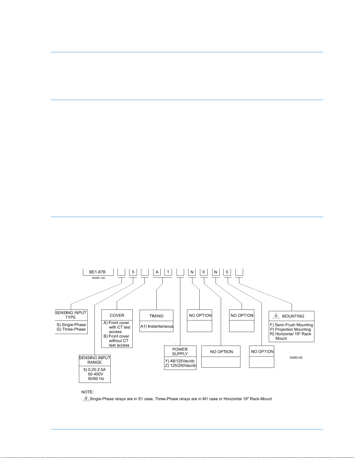
Figure 1-1. BE1-87B Style Chart ............................................................................................................... 1-1
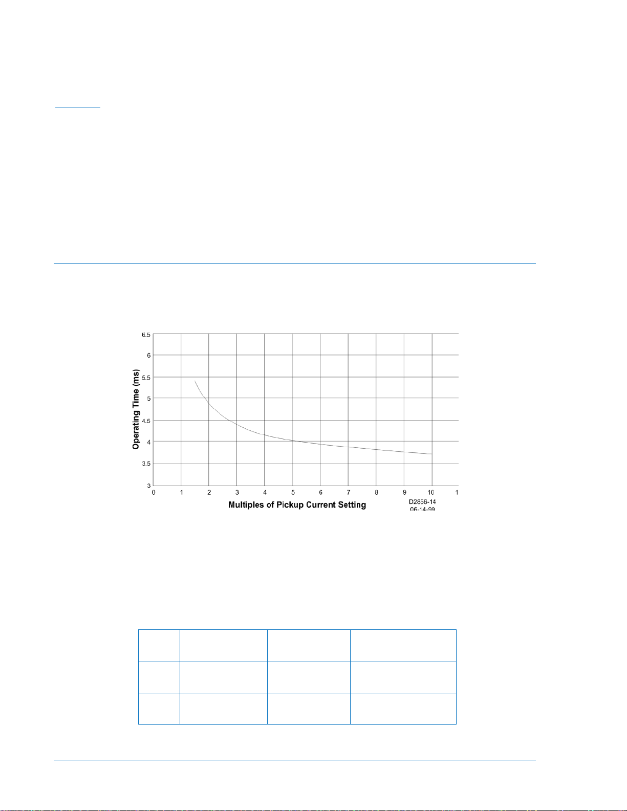
Figure 1-2. Typical Pickup Current Response Time without a Trip Delay................................................. 1-2
Tables
Table 1-1. BE1-87B Power Sup ply Spec i ficat ions .................................................................................... 1-2
Table 1-2. Input Impedance While Triggered and Not Triggered .............................................................. 1-3
9282300990 Rev P BE1-87B Application i
Page 12

ii BE1-87B Application 9282300990 Rev P
Page 13
SECTION 1 • GENERAL INFORMATION
General
The BE1-87B is a high-speed, high-impedance, soli d-state differential re lay. It was designed spec ifically
for bus differentia l pro tec ti o n. B ec ause of the relay’s high imp eda nc e, it c an be used in other applica tio ns ,
such as the protection of shunt reactors. Con tact your local Bas ler Applications Eng ineer for information
about additional applications.
Features
The BE1-87B offers high-speed fault protection, wh ich may be applie d to individual ele ments or zones of
ac power systems. It op erates in less than 7 mil liseconds for fault levels of 1.5 times the curren t pickup
and less than 5.5 milliseconds for fault levels above six times the current pickup. This high-speed
operation minimizes pot ential damage to the protect ed equipment. Response c haracteristics for sensin g
input ranges one and two are shown in Section 5, Testing.
Standard Features
Available in single-phase or three-phase models
• S1 and M1 double ended drawout cases and 19” rack-mount
• Percent of pickup voltage alarm
• Differential logic test
• LED trip output indicators
• Power supply status
• Ten position incremental adjust for the voltage and current pickup settings
Model and Style Number
The electrical characteristics and operational features included in a specific relay are defined by a
combination of letters and numbers, which constitutes the device’s style number. The style number
together with the model nu mber describ es the feature s and options in a particu lar device and a ppears on
the front panel as the item number. They also appear in the drawout cradle, and inside the case
assembly. The model number BE1-87B designates the relay as a Basler Electric Class 100, highimpedance bus differential relay. The style chart is shown in Figure 1-1.
Figure 1-1. BE1-87B Style Chart
9282300990 Rev P BE1-87B Application 1-1
Page 14
Style Number Example
The style number identif ication ch art defines th e electric al character istics and operation feat ures incl uded
in the BE1-87B relay. For ex ample, if the style num ber were BE1-87B S 5AA1YN0N0F, the dev ice would
have the following:
BE1-87B
S.......... Single-phase current sensing
5 .......... 5 ampere current sensing input range
A ......... Front case cover with CT test button access
A1 ....... Instantaneous timing
Y.......... 48/125 Vac/Vdc power supply
N ......... No Option
N ......... No Option
N ......... No Option
0 .......... No Option
F .......... Semi-flush case mounting
Specifications
Timing
A maximum of seven milliseconds at 1.5 times the pickup setting.
A maximum of 5.5 milliseconds above six times the pickup setting.
Figure 1-2 illustrates typical response times.
Figure 1-2. Typical Pickup Current Response Time without a Trip Delay
Power Supply
Power for the internal circuitry may be obtained from either an ac or a dc external power source as
indicated in Table 1-1.
Table 1-1. BE1-87B Power Supply Spec i fications
Type
Y 48/125 Vdc
Z 125/250 Vdc
1-2 BE1-87B Application 9282300990 Rev P
Nominal Input
Voltage
110Vac
110/230Vac
Input Voltage
Range
24 to 150 Vdc
90 to 132 Vac
60 to 250 Vdc
90 to 230 Vac
Burden at Nominal
(Maximum)
7.5 W
15.0 VA
7.5 W
20.0 VA
Page 15

Current and Voltage Settings
Voltage Alarm Pickup ............................. 10 to 80% in 10% increments
Voltage Pickup ........................................ 50 to 400 V in 50 V increments
Current Pickup ........................................ 0.25 to 2.5 A in 0.25 A increments
Table 1-2 describes input impedance w hile the SCRs are triggered (low impedance) and while the SCRs
are not triggered (high impedance).
Table 1-2. Input Impedance While Triggered and Not Triggered
Impedance State
Low Impedance (SCRs Triggered, Current Circuit Active) 0.05 0.05
High Impedance (SCRs Not Triggered, Voltage Circuit Active)
Input Impedance in Ohms
60 Hz Nominal 50 Hz Nominal
4000 - j3300
5100 ∠ –40°
4500 - j3100
5500 ∠ –35°
Frequency
Nominal 50 or 60 Hz, ± 5 Hz
Pickup Accuracy
±5% of the setting over the operating ranges for both current and voltage. Pickup accuracy over the ±5 Hz
nominal frequency variation is within ±8% of the nominal frequency value.
Output Contacts
Output contacts are rated as follows.
Resistive
120/240 Vac ............................................ Make and carry 30 Adc for 0.2 s , c arr y 7 Adc c ont in uo us ly, br eak
7 Aac
125/250 Vdc ............................................ Make and carry 30 Adc for 0.2 s, c ar ry 7 Adc continuously, break
0.3 Adc
Inductive
120 Vac, 240 Vac, 125 Vdc, 250 Vdc ..... Break 0.1 A (L/R = 0.04)
Current Rating
Continuous .............................................. 10 A rms
1 second, symmetrical ............................ 160 A rms
5 cycles, symmetrical ............................. 480 A rms
2 cycles, fully offset ................................ 215 A
Voltage Rating
The nature of the BE1-87B relay’s application is that voltage is not applied continuously. For calibration
and test purposes, it may be of value to apply input voltage for a longer duration than the few milliseconds
that would typify an internal or external power system fault. For test and calibration purposes, the BE187B has been designed to withstand 300 Vac for a maximum duration of 60 minutes.
Targets
LED indication (Trip LED) is latched with an internal, mechanical latching relay. Reset is accomplished by
pressing the Reset button on the front panel.
Isolation
In accordance with IEC 255-5 and IEEE C37.90, one-minute dielectric (high potential) tests were
performed as follows.
All circuits to ground ............................... 2000 Vac or 2828 Vdc
Each circuit to all other circuits ............... 2000 Vac or 2828 Vdc.
9282300990 Rev P BE1-87B Application 1-3
Page 16

Surge Withstand Capability (SWC)
Oscillatory and Fast Transient ................ Qualified to IEEE C37.90.1-1989
Impulse Test
Qualified to IEC 255-5.
Radio Frequency Interference
Maintains proper operation when tested for interference in accordance with IEEE C37.90.2 1995.
Electrostatic Discharge (ESD)
In accordance with IEEE C37.90.3, contact discharges of 8 kilovolts and air discharges of 15 kilovolts
were applied with no misoperation occurring.
UL Recognition
Recognized per Standard 508, UL File Number E97033.
Note that output contacts are not UL recognized for voltages greater than 250 V.
GOST-R Certification
GOST-R certified per the relevant standards of Gosstandart of Russia.
Environment
Temperature
Operating Range .................................... −40°C to 70°C (−40°F to 158°F)
Storage Range ........................................ −40°C to 85°C (−40°F to 185°F)
Humidity
Qualified to IEC 68-2-38, First Edition 1974
Shock
Qualified to IEC 255-21-2, Class 1.
Vibration
Qualified to IEC 255-21-1, Class 1.
Weight
1-phase Relay ......................................... 14.3 lb (6.5 kg) maximum
3-phase Relay ......................................... 19.2 lb (8.8 kg) maximum
Case Size
1-phase Relay ......................................... S1
3-phase Relay ......................................... M1 or 19” Rack-Mount
Case dimensions are provided in Section 4, Installation.
1-4 BE1-87B Application 9282300990 Rev P
Page 17

SECTION 2 • APPLICATION
TABLE OF CONTENTS
SECTION 2 • APPLICATION .................................................................................................................... 2-1
Application.............................................................................................................................................. 2-1
Application with Lightning Arr es ters ................................................................................................... 2-1
Application with a Lockout Function ................................................................................................... 2-1
Current Source for High Impedance Differential Relaying ................................................................. 2-1
BE1-87B Flexibility ................................................................................................................................. 2-2
Bus Protection Application ................................................................................................................. 2-2
Shunt Reactor Protection Application ................................................................................................ 2-4
Mixing Two Different Ratio CTs ......................................................................................................... 2-5
General Settings Guidelines .............................................................................................................. 2-5
Operating Principles ............................................................................................................................... 2-5
External Faults ................................................................................................................................... 2-6
Internal Faults ..................................................................................................................................... 2-7
Characteristics ..................................................................................................................................... 2-10
Differential Voltage Pickup ............................................................................................................... 2-10
Differential Pickup Current ............................................................................................................... 2-10
Alarm Voltage Pickup ....................................................................................................................... 2-10
Trip Test Pushbutton ........................................................................................................................ 2-11
CT Test Pushbutton ......................................................................................................................... 2-11
Power LED ....................................................................................................................................... 2-11
Intentional Delay Jumper.................................................................................................................. 2-11
Operating Times ............................................................................................................................... 2-11
Calculation of Settings ......................................................................................................................... 2-12
Calculation of Voltage Differentia l Sett in gs ...................................................................................... 2-12
Bus Protection .................................................................................................................................. 2-13
Shunt Reactor Protection ................................................................................................................. 2-13
Application with Mixed Multi-Ratio CTs ............................................................................................ 2-13
Current Element Setting ................................................................................................................... 2-14
Minimum Fault to Trip (Voltage Element) ......................................................................................... 2-14
Sample Calculation .............................................................................................................................. 2-15
CT Test Circuit Calculations ................................................................................................................ 2-16
General ............................................................................................................................................. 2-16
Definition of Terms ........................................................................................................................... 2-16
Calculation Steps ............................................................................................................................. 2-17
Example Calculation ......................................................................................................................... 2-17
Figures
Figure 2-1. External AC Connections for Bus Protec t io n .......................................................................... 2-3
Figure 2-2. External DC Connections for Bus Prot ection .......................................................................... 2-4
Figure 2-3. External AC Connections for Shunt Reactor Protection, Multi-Phase and Line-to-Ground
Faults ......................................................................................................................................................... 2-4
Figure 2-4. External AC Connections for Shunt Reactor Protection, Ground Faults ................................ 2-5
Figure 2-5. Illustration of Single Line-to-Ground Fault at Location F1 ...................................................... 2-7
Figure 2-6. Typical Secondary Excitation for 1200/5 Bushing Current Transformer ................................. 2-8
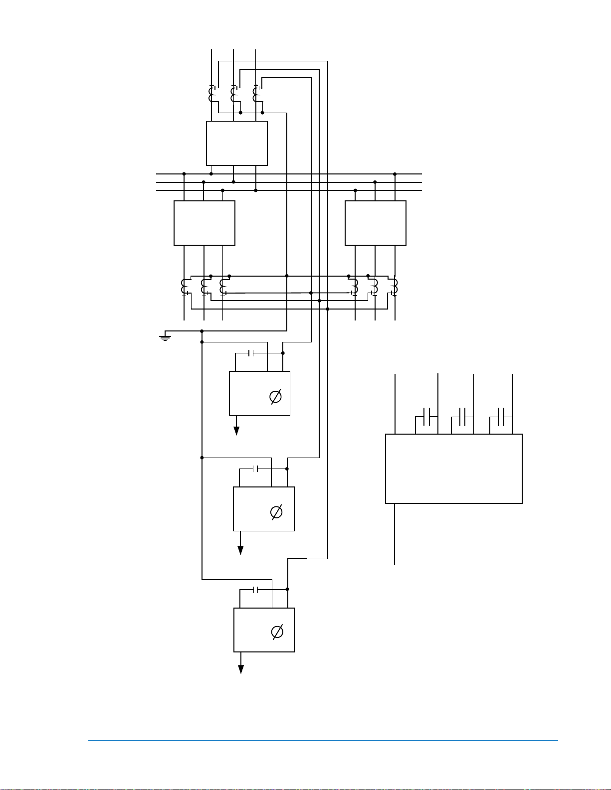
Figure 2-7. Simplified Internal Connection Diagram for BE1-87B Relay ................................................... 2-9
Figure 2-8. Voltage Appearing Acros s Ful l Windi ng of CT ...................................................................... 2-10
Figure 2-9. Voltage Appearing Acros s Ful l Windi ng of CT ...................................................................... 2-17
Figure 2-10. Voltage Appearing Acr os s Full Wind ing of CT .................................................................... 2-18
9282300990 Rev P BE1-87B Application i
Page 18

ii BE1-87B Application 9282300990 Rev P
Page 19

SECTION 2 • APPLICATION
CAUTION
CAUTION
Application
The BE1-87B solid-state, high-speed, high-impedance differential relay is available in single or threephase models. The relay was specifically des igned to provide high-s peed differential protection for high
voltage buses, critical medium, and low voltage buses. Because of its design and sensitivity, the relay can
also be used for shunt reactor protection. While bus schemes require three-phase protection, shunt
reactors may be protected with only one single-ph ase relay for ground faults . Regardless of the scheme
employed or the equipment protected, the following applications apply to the BE1-87B relay.
Application with Lightning Arresters
The BE1-87B is a hig h-speed relay des igned to operate in a half-cycle or less . As a result, apply ing the
relay to a bus wit h lightning arresters must b e addressed. The relay pick up current range is adjustab le
between 0.25 to 2.5 amper es rms. If lightning ar resters will b e connected to the bus, use the 2.5 amper e
sensitivity setting so as to prevent the possibility of a differential operation during a normal arrester
operation. If no light ning arres ters ar e use d, start with t he 0. 5 amp ere sens itivi ty setti ng and adjus t as the
application dictates.
If lightning arresters ar e added to an exis ting bus, as might be the case w hen
adding a transformer, be sure to increase the Pickup Current setting of the
BE1-87B to the 2.5 ampere setting.
Application with a Lockout Function
Contacts from the lockout relay (86) should be connected across terminals 5 and 6 (single-phase or
phase A for 3-phase models), 3 an d 4 (phase B), and 1 an d 2 (phase C) of the BE1-87B relay to shor tcircuit the SCRs in the inpu t circuit after a trip ou tput has been initiated. This al lows the relay to con tinue
operation as a conventiona l overcurrent relay and at t he same time protect agains t exceeding the shorttime rating of the internal SCRs. The relay can be used in any application where the total secondary
current is not more tha n the current waveform of a fully-offset f ault with 215 amperes rms symmetric al
available, provided the lockout relay (86) has an operate time of 1 cycle or less (16 milliseconds).
If the BE1-87B relay co ntrol power (power supply voltage) is removed, relay
terminals 5 and 7 (single-phase model) or 5 and 7, 3 and 7, and 1 and 7
(three-phase model) should be short ed by pull ing the connect ion pl ug. If th is is
not done, the BE1-87B relay c ould b e da mag ed d ue t o c ontin uous f aul t c urr ent
flowing through the relay SCRs.
Current Source for High Impedance Differential Relaying
Predictable current trans former (CT) performanc e is critic al to the eff ective oper ation of a high impeda nce
differential scheme. Where prac tical, t he following current tr ansformer guide lines s hould be appl ied when
using the BE1-87B relay.
• All CTs should be of toroidal design and be fully distributed around the core.
• All CTs should have the same full ratio value and be connected to the full ratio taps.
• All CTs should have the same voltage rating, accuracy class, and thermal rating.
• The CTs should be dedicated to the differential application.
• When adding to an existi ng differenti al scheme, a t lea st one set of CTs in the ne w breaker shou ld be
ordered with the same ratio and accuracy class as the differential CTs used in the existing scheme.
• CTs cannot have pr imary or secondary voltage limiti ng devices, as the resulting shor t-circuit could
cause an unwanted operation of the differential.
9282300990 Rev P BE1-87B Application 2-1
Page 20

BE1-87B Flexibility
Because of the flexible wid e range design of the BE1-87B, it is possible to ap ply the relay in situations
where the current sensin g input circuit is less tha n ideal. It should be noted, however, that th e possibility
of less sensitive settings, equipment overvoltage, or false operation could resu lt. Careful review of the
following application notes is recommended:
• It is possible to use a m ixtu re of mult i-ratio CTs , howe ver, it is essent ial th at the tapped value h as the
same turns ratio as the other para llel CTs in the circuit. When ta ps are selec ted other than f ull ratio,
use the highest available ta p s etting th at w ill a llow all CT s in the sc heme to hav e t he s ame turns r atio .
Tap settings other than full ratio re quire a calculation of the peak vo ltage developed across the full
winding resulting fro m autotransfor mer action. Th e resulting v oltage shou ld not ex ceed the insula tion
breakdown values of the connected equipment. The equation for this calculation is derived in the
paragraph on operating pr inciples in this section and repeated in the paragraphs on Calculation of
Settings.
• All CTs used in the differential circuit should have negligible leakage reactance on the connected
taps. Most, if not all, multi-ratio internal, bushing, and column type CTs made in the last 30 years
meet this requirement. All CTs wound on toroidally shaped cores meet this requirement if the
windings (on the tap used) are com pletely dis tributed around th e core (co nsult y our CT manufacturer
if you have questions). It m ay be pos sible to us e CTs t hat do not me et th is requir ement if the leak age
reactance is known. T he leakage reac tance is added algebraically to t he resistanc e of the CT circui t
in question. Less sensitive protection will occur as a result of a higher pickup setting.
• It may be possible, although not recommended, to use the differential circuit CTs jointly for other
functions as long as an accur ate impedance of the other functi on is known. The performance of the
system under these c onditions can be ca lculated by alge braically adding th e other impedanc e to the
CT winding and cab le resistance. Less sens itive protection will occ ur as a result of a hi gher pickup
setting. Also, considerat ion must be given to the haz ards of false operatio n due to extra connections
and errors in test ing the added devices . To ensure pr oper relay setting, all cable and CT sec ondary
winding resistances should be ev aluated before a decision is made to a dd other devices to th e BE187B CT circuits.
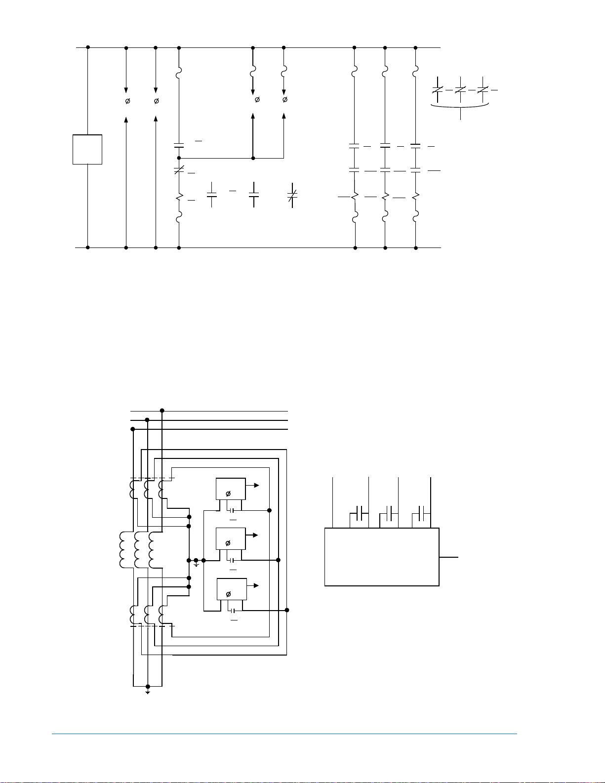
Bus Protection Application
Three single-phase BE1-87 B r elays or one t hree-phase BE1-87B relay and an aux iliar y loc kout relay (86) ,
provide a complete m ulti-p hase and gr ound bus fault protection package. Typical external c onnect ions to
the relays are shown in Figures 2-1 and 2-2. The connections are illustrat ed for a bus w ith three circ uits,
but the protection can easil y be ex tended if more c ircu its are adde d to the bus . For addit ional circ uits, it is
only necessary to connect the CTs associated with the added circuits to the respective junction points and
to connect the contac ts of the lock out relay in the r espective trip c ircuits. The rel ay voltage tap s etting is
based on the maximum voltage that can be developed across the differential junction point during an
external fault. Calc ulation of the max imum voltage is easily made an d methods fo r doing so are giv en in
the paragraph under calculation of settings. A sample calculation for a bus differential scheme is also
provided.
2-2 BE1-87B Application 9282300990 Rev P
Page 21
TO SURGE
GROUND
52-1
52-3
52-2
3 2 1
3
2
1
3
2
1
TO SURGE
GROUND
Single Phase
87B- 1
RELAY HOUSE
GROUND
TO SURGE
GROUND
D2853-3
5-26-99
86
567
86
5
6
7
86
5
6
7
Single Phase
87B- 2
Single Phase
87B- 3
86
86
86
Three Phase
87B Relay
1
23
4
5
6
7
N
1 2 3
Surge
Ground
Figure 2-1. External AC Connections for Bus Pr otection
9282300990 Rev P BE1-87B Application 2-3
Page 22
86 86 86
BLOCK AUTOMATIC
RECLOSING
86
87
86
87
52-1
52-252-1
52-3
52-2
52-3
86 86 86
a
aa
TC
TC
TC
(+)
(-)
D2853-4
5-24-99
87 - BE1-87B BUS DIFFERENTIAL RELAY
86 - LOCKOUT RELAY
15
16
17
18
TRIP 1
OUTPUT
TRIP 2
OUTPUT
19
20
87
13
14
VDIFF
ALARM
11
12
RELAY
TROUBLE
TO 2 AND 3
SINGLE PHASE RELAYS
TO 2 AND 3
SINGLE PHASE RELAYS
BE1 - 87B
86
BE1 - 87B
86
BE1 - 87B
86
1
2
3
01
0203
86 - LOCKOUT RELAY
* TO SURGE GROUND
*
*
*
1
2
3
D2853-5
5-25-99
5
6
7
5
6
7
5
6
7
86
86
86
Three Phase
87B Relay
1
23
4
5
6
7
N
1 2 3
*
Figure 2-2. External DC Connecti ons for Bus Protec t io n
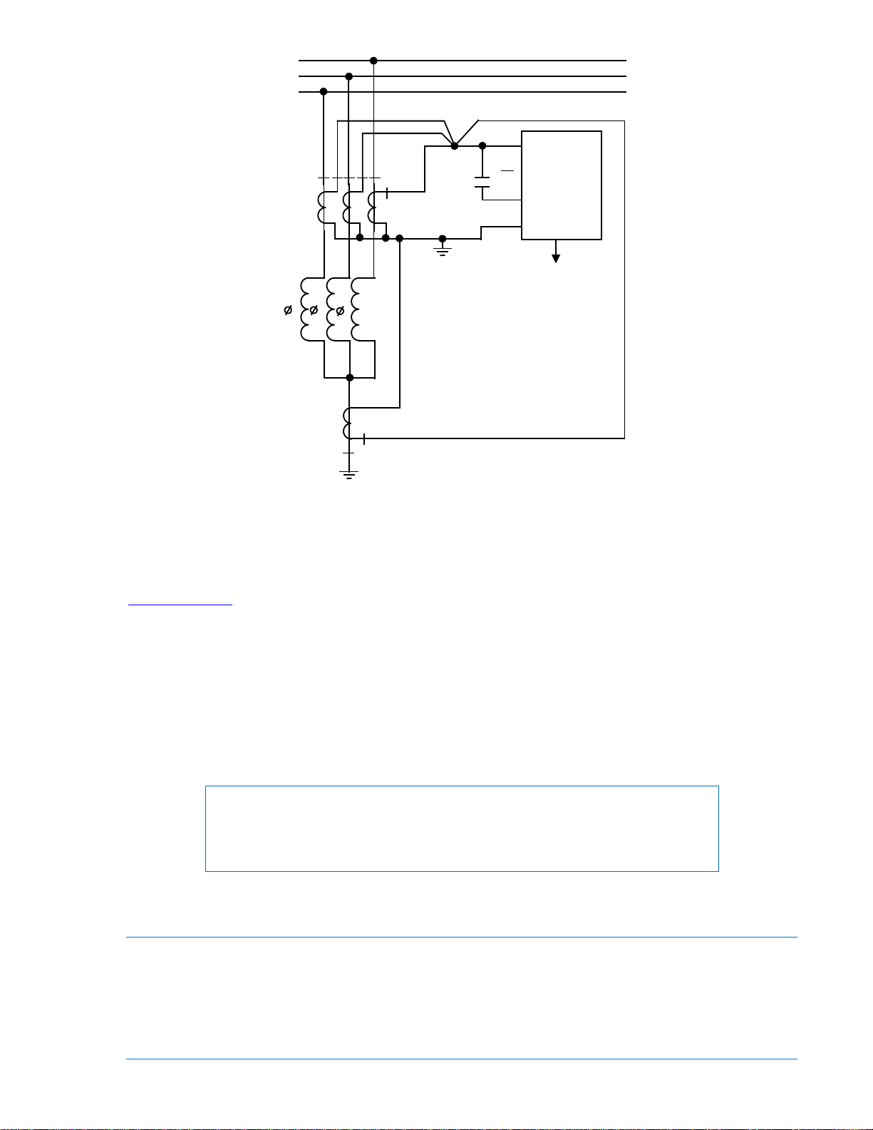
Shunt Reactor Protection Application
Differential protection of s hunt reactors may be pr ovided by using only one sin gle-phase BE1-87B relay ,
three single-phase relays, or one three-phase relay. Typical ac external connec tion diagrams for these
schemes are shown in Figures 2-3 and 2-4. The dc connections will be similar to those show n in Fig ure 2-
2. Only ground fault protection will be provided when one relay is applied. Application of either three-
phase arrangement wi ll provide both multi-phase an d phase-to-gro und fault prote ction. Calcu lation of the
voltage tap setting is basically the same as for the bus app lication. The procedures for calculating the
voltage tap setting for either scheme are provided under Calculation of Settings.
2-4 BE1-87B Application 9282300990 Rev P
Figure 2-3. External AC Connections for Shunt Reactor Protection,
Multi-Phase and Line-to-Ground Faults
Page 23
BE1 - 87B
5
6
7
86
TO SURGE
GROUND
1
2
3
1
2
3
86 - LOCKOUT RELAY
D2853-6
5/25/99
Figure 2-4. External AC Connections for Shunt Reactor Protection, Ground Faults
Mixing Two Different Ratio CTs
While high impedance bus protec tion is bes t conf igure d with all CT s hav ing a co mmon rat io, it is p ossibl e
to utilize two different ratio CTs within one bus protection zone. The process by which this is
accomplished is detailed in the paper “Bus Protective Relaying, Methods and Application” located at
www.basler.com
.
General Settings Guidelines
To obtain the max imum set ting sens itivity, the CT loop res istance shou ld be minimized s o that the low est
possible voltage setting can be selected. For switchyard applications where there is a large distance
between the breaker and the relay panel, it may be desirable to locate the differential junction in the
switchyard since the resistance of the fault CT loop may otherwise be too large. To minimize the
impedance from the current transformers to the junction point, all the secondary windings should be
paralleled in the swi tchyard and as clos e as possible to the c urrent transformer s. Optimally, the junction
point should be equidistant from all current transformers.
The cable resistance fr om the junction point to the re lay is not included as a
part of the fault CT l oop r esistanc e. It is perm issibl e to locate junctio n poi nts at
the panel, providing that the relay setting gives the desired sensitivity.
NOTE
Operating Principles
The BE1-87B high impedance, differential relay operates on the instantaneous value of CT secondary
voltage to which the relay is connected. All the CTs in the differ ential circuit must have the same tur ns
ratio. If all CTs hav e the same turns ratio, the volta ge developed acros s the relay duri ng normal system
conditions is very small. Th e diagram in Figure 2-1 illus trates typical external ac connections to the relay
for use in a bus differential sc heme. As shown in the diagram, a typical differential connec tion is used
consisting of the CT circuits from each bus device connected in wye and paralleled at one location
9282300990 Rev P BE1-87B Application 2-5
Page 24

(summing point) on a per-phase basis. Three single-phase BE1-87B relays or one three-phase relay
)2R(R )(I 22 Vpeak
LSF
+=
)2R(R IV
LSFR
+=
provide complete protection of the bus. The relay will generate a trip output when the instantaneous
voltage applied across 5 and 7, or 3 and 7, or 1 and 7 o f the thr ee-phase model (A, B, and C res pec tive ly ),
exceeds the voltage pickup setting (V
) and the fault current is greater than the current sensitivity
DIFF
setting.
External Faults
If the differential protection scheme is to perform satisfac torily, then it must not trip for faults external to
the zone of protection . For example, Figure 2-5 shows a on e-line diagram for a three input diff erential
scheme. The BE1-87 B must not operat e for a fault at F1. Since the CT s in the faulted f eeder (CT 3) will
see the most current , assume they will saturate completely, thus causing t he magnetizing reactance to
drop to zero. The total current fr om the other CTs (CT 1 and 2) is for ced through the par allel comb ination
of the high impedance relay (5,000 Ω) and the saturated CT secondary. The saturated CT secondary
winding resistance is i n series with any resistance of the CT leads and connection cables (the total of
which presents a much lower resistance than the 5,000 Ω).
Therefore, nearly all the secondary fault current will flow through the saturated CT. A voltage drop V
caused by the flow of the fault curr ent in this parallel path will a ppear across the BE1-87B relay. For this
fault, the highest volta ge th at coul d be dev elop ed at th e relay w ould oc cur when t he assoc iated CT (CT 3)
saturates completely, an d the others ( CT1 and CT2) did not sat urate at all. When a CT with a distributed
toroidal winding (on t he tap used) saturates complet ely, it produces no voltage and the impedance, as
seen at the secondary w inding, is ver y nearly equal to the winding resistance ( very small impedance).
Thus the highest peak voltage that can be developed across the relay during an external fault will be
equal to the voltage produced by the total secondary fault current flowing through the control cable
resistance plus the wi nding res istance of the CT asso ciated wit h the faulte d feed er. Refer to th e exampl e
case in Figure 2-5 while applying Equation (1):
R
(EQUATIO N 1)
I
= rms symmetrical value of fault current in the fault CT in secondary amps.
F
R
= CT secondary winding resistance plus any lead resistance (at highest expected operating
S
temperature)
= Cable resistance from junction point to CT (at highest expected operating temperature)
R
L
Equation (1) above yi elds the p eak volt age develop ed at the r elay for a complet ely offset wav e of curr ent
having an rms symmetrical value of I
secondar y amperes. Because the BE1-87B relay is cal ibrated in
F
symmetrical rms volts, Equation (2) below, whic h yields the r ms voltage v alue, is us ed in the paragra phs
on Calculation of Settings.
(EQUATION 2)
The pickup voltage of the B E1-87B mus t be set abov e this valu e of rms volt age and above t he rms value
of the other voltages o btain ed in a si milar m anner on a ll the cir cuits of the b us. B ec ause the peak vo ltage
is proportional to the fault c urrent, the highest pos sible v alue of expected f ault cur rent in rms sy mmetrical
amperes should be used in making the evaluation.
2-6 BE1-87B Application 9282300990 Rev P
Page 25

Figure 2-5. Illustration of Single Line-to-Ground Fault at Location F1
Internal Faults
During internal faults on the bus, al l of the CTs will be oper ating into the re latively high impe dance of the
BE1-87B. Under thes e c o n dit ions, the maximum funda ment al fr equ ency v olt age t hat c an be pr od uc ed w ill
be limited to values as dictated by the CT secondary fund amental frequency excitation charac teristics.
Examination of a typical CT secondary excitation characteris tic will show that the available fundam ental
frequency voltage flattens off beyond the knee of the curve. However, the peak voltages that can be
produced are not indicated on the stan dar d exc itat ion c urv e.
The concept of how the CT responds during an internal fault is given in greater detail in the p aper “Bus
Protective Relaying, Methods and Applic ation” located at www.basler.com
to say that, for interna l faults , the peak volta ges will alway s be great er tha n indic ated by t he avera ge, and
will continue to incr ease in magnitude as the exc itation is increased. Becaus e the peak voltages durin g
internal faults will be much greater than the peak voltages experienced during external faults, and
because the BE1-87B relay operates as a function of the instantan eous voltage, the relay can be s et to
be selective between internal and external faults. An indication of the peak voltages that a CT can
produce can be determined by a simple modification to the CT secondary excitation characteristic.
The modification is shown by the lines CPB in Figur e 2-6, which now def ine the excitati on characteris tics
as a function of the peak voltages. Stu dies have shown th at the peak voltages produced will be at least
equal to or greater than those established by the modified characteristics. These characteristics are
useful in determining the minimum internal fault for w hich the relay will operate. The m ethod for making
the modifications, and the ir us es in determ ining t he se nsitivity , are prov ided in t he Calculation of Sett ings,
Minimum Fault to Trip sub-section in this chapter.
. Let us summarize the matter
9282300990 Rev P BE1-87B Application 2-7
Page 26

Figure 2-6. Typical Secondary Excitation for 1200/5 Bushing Current Transformer
Figure 2-7 illustrat es, in simplified form, the internal connections of the BE1-87B relay. When an inter nal
fault occurs, the peak volta ge developed in the secondary of the feeder CTs will appear ac ross the relay
input network via phase A, phase B, or phase C. Under normal conditions, while operating power is
available to the relay, the SCR firing is accomplished via the voltage sensing circuitry by the pulse
amplifier. When the SCRs fire, the CT circuits will be shorted and the total secondary fault current will flow
through the SCR circ uits and the primary of current t ransformer T1. If the total secondary fault current,
and hence the primary current of T1 is above the pickup level of the relay , a trip output wil l be provided
via the output relay.
When relay-operating power is not available, the BE1-87B can no longer trip the output contacts.
However the SBS (Silicon Bilateral Switch) circuitry provides voltage protection for the SCRs and the
relay internal circuitr y. When the peak v oltage exceeds the swi tching voltage of t he SBS, it will con duct,
causing the correspond ing SCR to be triggere d to the ON condition. During subsequent ha lf cycles, the
SCRs will be trigg ered alternately. Note t hat the SBS, acros s the SCRs, exhibits high impedance in the
OFF state and will turn ON and conduct whe n a switching voltage above the relay maximum s etting is
reached. The SBS ac ts only as a fails afe, triggering the SCRs in the even t control power (p ower supply
voltage) is lost and a fault has occurred.
2-8 BE1-87B Application 9282300990 Rev P
Page 27

Figure 2-7. Simplified Internal Connection Diagram for BE1-87B Relay
)(V (2.83) )(V 22 V
DIFFDIFFR
==
22
2
1DIFF
R
2
1
F
N
)(N )(V (2.83)
)(V
N
N
V ==
22
For convenience, th e BE1-87B relay voltage s ettings are c alibrat ed in terms of r ms sy mmetrica l vo lts and
all calculations for setti ngs are made in terms of rms sy mmetrical quantities. The relay responds to the
instantaneous value of applied voltage, and this maximum instantaneous value can be two times the
square root of two or 2.83 times V
for fully offset waveforms. As soon as the relay operates, the
DIFF
shorting action of the SCR path r educes th is voltage to a ver y low level . Th us the m axim um peak volt age
that can be produced in the differential circuit will be limited to the value calculated in Equation 3 below.
(EQUATION 3)
V
= maximum instantaneous peak voltage that can be developed in the differential circuit
R
V
= BE1-87B voltage set point in rms symmetrical volts
DIFF
) = conversion of rms symmetrical volts to corresponding peak volts of a fully offset voltage wave
(
Where CTs with taps set o n other t han the f ull wi ndin g are inv olved, the v olta ge dev elope d acros s the fu ll
winding of these CTs c an be greater t han the differ enti al circuit volta ge as a resu lt of the aut otransfor mer
action. For example, c onsider the simple circuit of F igure 2-8. The voltage in the differential circuit, an d
consequently across C T1 a nd CT 2, wi ll b e l imite d to V
. But the voltage across the ful l wi ndi ng o f CT 3 w il l
R
be greater by the ratio of the total number of turns of the CT to the actual turns used.
(EQUATION 4)
= voltage across the full winding
V
F
N
= total number of CT secondary turns
1
N
= number of CT secondary turns used, i.e. tap settings
2
2.83 =
The voltage across the full winding (V
(peak value of fully offset wave)
) should not exceed the insulation breakdown of the connected
F
equipment. The val ue of t h e ac tu al pe ak v olt age th at can be produced f or any relay tap sett ing an d mixed
multi-ratio CT combination may be evaluated using Equation (4).
9282300990 Rev P BE1-87B Application 2-9
Page 28

whenever an rms symmetrical
BE1-87B
N2
N1
V
N2
CT1
N2
CT2
CT3
VF=
N1
N2
VR
V = VOLTAGE DEVELOPED ACROSS FULL WINDING
V = MAXIMUM INSTANTANEOUS VOLTAGE
NI = TOTAL NUMBER OF CT TURNS
N2 = NUMBER OF CT TURNS USED (TAP SETTING)
D2853-10
5-25-99
F
R
R
VF
Figure 2-8. Voltage Appearing Acros s Full Windi ng of C T
Characteristics
Operation of the BE1-87B relay is initiated as a function of the instantaneous voltage developed across
terminals 5 and 7 (s ingle-phase mode l) of the relay. Howev er, an output will not be produced unles s the
total secondary fault cur rent that flows through the relay after the SC Rs fire is greater than the pickup
current setting. In t his fashion both voltage and current are required to pr oduce an output. The volt age
selector switch settin g and curr ent selector s witc h setti ng determi ne the v oltag e and c urrent req uire ments
needed to produce an output.
Differential Voltage Pickup
The BE1-87B pickup volta ge selector switch allows for a setting rang e of 50 to 400 volt rms sy mmetrical
in 50-volt increments. This s ets the voltage lev el at which the back to back intern al SCRs will trigger . The
SCRs will trigger whenever the instantaneous value of the applied voltage is equal to twice the peak value
of the rms symmetrical pickup voltage setting. Refer to Equation 3.
NOTE
The voltage VR is equal to the peak voltage of a fully offset voltage wave
having an rms symm etrical value equal to the pic kup voltage selector switch
setting. Because of this the SCRs will fire
voltage greater than twice the voltage selector switch setting is applied, or
whenever the corresponding peak voltage is exceeded on an instantaneous
basis as in the case of an interna l fault. When the SCR s fire, prov ided th e total
secondary fault cur rent t hat flows in the relay is greater than the p ick up c urr en t
setting, the relay will produce an output.
Differential Pickup Current
Pickup current is defined as the rms value of a sy mmetrical sinus oidal current th at must flow into the 8 7B
in order to provide a contact output. T he BE1-87B has a pickup cur rent selector switch that allows for a
range of 0.25 to 2.5 amperes rms in 0.25 ampere increments. However, the relay internally operates off of
the instantaneous pe ak of this sinusoidal curr ent. For example, if the re lay is set at 1 amp, the cur rent
sensing element monitors for instantaneous current riding above 1.414 amps.
Alarm Voltage Pickup
The BE1-87B is equipped with a different ial voltage alar m function. The fu nction is used to det ect steady
state voltage imbalances across the input sens ing circuit of the relay (Terminals 5 and 7, 3 and 7 , and 1
2-10 BE1-87B Application 9282300990 Rev P
Page 29

and 7 for the three-phase model). The setting range for the alarm pickup is 10% to 80% of the rms
CAUTION
differential voltage pic kup setting (V
input terminals exc eeds the voltage pickup s etting times the voltag e alarm percentage sett ing (V
) in increments of 10%. W hen the rms voltage acr oss the sensing
DIFF
DIFF
x %
set), the CT OV LED illuminates and the alarm output contact closes (T erminals 13 and 14). W hen the
input voltage falls below th e alarm voltage threshold, the CT OV LED turns OFF and the alarm outp ut
contacts open. The response time of the alarm contacts and the LED is intentionally slow to prevent
nuisance alarms (ap proximately one seco nd). If th e Shorted CT Test Cir cuit is u sed, set the a larm un it at
minimum (10%).
Example:
A relay with a d ifferential pickup voltage (V
alarm voltage setting of 10%, will alarm at 20 volts rms (200 x 0.1 = 20 volts).
) setting of 200 vo lts rms symmetrical and an imbal ance
DIFF
Trip Test Pushbutton
The Trip Test pushbutton i s recessed behind the front panel and is accessed through a small opening.
Insert a small, nonc onductive tool throug h the front panel to de press the Trip Tes t pushbutton. Trip test
simulates a trip condit ion and verifies the operation of both out put trip contacts and the trip LED. Upo n
releasing the Trip T es t pushbutton, the trip outp ut co ntacts will reset, but the L ED r emai ns l it. T o clear the
Trip LED indication, press the Reset button.
Activation of the Tri p Test button will trip the loc kout device (86) and the bus
breakers unless appropriate steps are taken.
CT Test Pushbutton
The CT Test pushbutton is a “pillow-type” button located on the face of the relay. The button can be
accessed by either removi ng the st andard c over to ac tuate or throu gh th e externa l button ac tuators of the
optional cover. The CT Test pushbutton provides a method for tes ting the “health” of the en tire current
circuit by injecting a calculated value of external test voltage across the current circuit. If the current circuit
is healthy, the voltage acr oss the relay will be high enough to light the Alar m LED and close the alarm
output contacts, termina ls 13 and 14. If there is a short c ircuit in the current circuit, all of the tes t voltage
will be dropped acr oss an external test r esistor and neith er the LED nor the alarm output will o perate. If
this occurs, further c ur ren t circuit tests shoul d be perf o rmed. This function is av a ilabl e o nly w hen power is
applied to the relay and the CT diagnostic test source assembly (9282300014) is connected to terminals 7
and 10 of the relay. The Test Circuit Calculations sub-section provides details on applying this featur e.
Power LED
This LED lights when normal operating power is applied to relay terminals 15 and 16.
Intentional Delay Jumper
A user-settable jum per is lo cated on t he Control c ircuit board to select e ither no i ntentional delay ( jumper
position 1 to 2), or a 20-mill isecond delay∗ (jumper pos ition 2 to 3) added to the trip response t ime. For
applications having a tap within the zone of protection that is protected by a high-speed fuse, the 20
millisecond intentional delay∗ is intended to prevent tripping the bus for a fault on the fused tap. The
current detector circ uit rese t time is appr oximately 1 mil lisecond so t hat the ac and dc c omponents of the
differential current, as reproduced at the CT secondary, must drop below pickup in less than 19
milliseconds. A second ary error may occur due to the fast dropout of the primar y current when the fuse
operates.
∗ Ac tual intentional time delay is a functio n of pickup current. For currents ex ceeding twice the pickup
setting, intentional time delay is 20 milliseconds. For currents less than twice the pickup setting,
intentional time delay is 25 milliseconds.
Operating Times
The BE1-87B operates in less than 7 milliseconds (1/2 cy cle) for faults 1.5 times the cur rent pickup. The
BE1-87B operates in less than 5.5 milliseco nds for fault levels above 6 times the current pickup. High-
9282300990 Rev P BE1-87B Application 2-11
Page 30

speed operation minimizes potential damage to th e protected equipm ent. Refer to Figures 1-2 and 1-3 in
N
I
)PR (R 1.25 V
F
LSDIFF
+=
Section 1, General Infor mat ion for illustrations of response times.
Hold Timer
The BE1-87B has a hold timer (200 milliseco nds, fixed) that prev ents the Trip output relay contacts from
opening prematurely.
Calculation of Settings
The BE1-87B relay is set bas ed on the max imu m poss ible voltag e that can be pr oduced in the differ entia l
circuit as a result of a fault external to the zone of protec tion. Determination of t he maximum voltage for
this condition is subject to simple calculations , and thus, the relay s etting is easily determ ined. The relay
has a setting range 50 to 400 volts rms in 50-volt steps.
It is first necessary to c alculate t he max imum vo ltage t hat can b e pro duced in the different ial cir cuit for an
external fault. Once that value is determin ed, th e appr opr iate vo ltage s etti ng ca n be se lecte d. If a mixtur e
of multi-ratio CTs is used (not recommended) or if the CTs are applied on taps other than full ratio,
calculations must be performed to determine if excessive voltages will be produced across the full winding
of the CT. Last, the mini mum internal fault for which the relay will just operate will be calculated.
Calculation of Voltage Differential Settings
The minimum acceptable differential voltage setting can be determined using the following equation.
(EQUATION 5)
V
= minimum acceptable vo ltage tap setti ng. Since V
DIFF
one of the available settin g s , the next higher s etti ng should be used. The available v oltage set t in gs ar e 50
to 400 volts rms in 50-volt increments.
= dc resistance of fault CT secondary windings and leads to the CT makeup box (at maximum
R
S
expected operating temperature).
= s ingle conductor dc res istance of the curr ent circuit cable for a one-way run fr om the different ial
R
L
junction point to the fault CT makeup box (at maximum expected operating temperature).
P = one (1.0) for three-phase faults and (2.0) for single-phase to ground faults.
I
= maximum external fault current in the fault CT in primary symmetrical rms amperes.
F
N = CT ratio.
1.25 = margin for safety.
The following comments may be made with respect to the evaluation of Equation 5.
• It is only necessary to calculate three-phas e and single-phase-to-grou nd faults. If the results yield a
satisfactory application, the application will also be satisfactory for multi-phase faults.
• For single-phase-to-groun d faults, the differential circuit is such that the CT secondary fault current
will flow through both of the fault CT cables; th us the multiplier P must be set equal to two. On the
other hand, the CT sec ondary currents dur ing a balanced three-p hase fault will r esult in 0 current in
the return cable; thus only the one-way cable resistance is involved, and P is set equal to one.
• If the single-phase-to-gr ound fault current at a given location is greater than or equal to the three-
phase fault current, the calculations need only be made for the single-phase-to-ground faults.
• The resistance of t he CT s and connecting cables w il l inc r ease with increasing te mperature; therefore,
if adequate margin is to be maintained at all t imes, Equation 5 shou ld be evaluated usi ng resistance
values corresponding to the maximum expected operating temperature (see sample calculation in this
section).
The methods to be used in calc ulating the voltage tap setting using Equation 5 will to some extent be
dependent on the typ e of appl ication. T he follow ing paragr aphs discus s different areas in which t he BE187B relay may be applied.
in genera l will not come o ut exactly equal t o
DIFF
2-12 BE1-87B Application 9282300990 Rev P
Page 31

Bus Protection
Two methods will be out lin ed for ev alua ting Equat ion 5 in or der t o deter mine a n appropr iate re lay vo ltage
tap setting.
Method 1. The first m ethod offers a simplified conse rvative approach to the probl em and requires that
equation 5 be evalua ted only once. With this method, it is assumed that a s ingle-phase-toground fault with a current magn itude equa l to th e maximum interru pting r ating of the breaker
occurs on the feeder assoc iated wit h the CT hav ing th e longest c able run fr om the diff erent ial
junction point. Under thes e assumptions, the effect of the fau lt current, I
, is maximized, and
F
so is the effect of cable resis tance, becaus e the highe st value of res istance is used and P is
set equal to 2. Thus, the highest possible value of V
will be obtained.
DIFF
Method 2. The second method offers an exact approach b ut requires that Equation 5 be eval uated a
number of times in order t o obtain th e maximu m V
. With this method, calcul ations must be
DIFF
made for the maximum single-phase-to-ground fault a nd the maximum three-phase fault just
off each of the n fee der s on the bus . Ther e f ore, E quat i on 5 m us t b e evaluated 2n times us in g
the associated value of cable resistance and P = 1 or P = 2, as required.
In general, Method 2 will p roduce a lower voltage tap s etting than Method 1, but Method 1 is s impler to
utilize. The user sho uld begin with Meth od 1. If the volta ge setting resulting from the use of this method
results in adequate sensitivity, a unique advantage is realized in that the setting does not require
recalculation following future changes in the power system that result in higher fault current magnitudes. If
the sensitivity resulting from the use of Method 1 does not prove adequate, then Method 2 should be
used. Each method is outlined below.
Method 1 (Simplified Conservative Approach)
a. Use the maximum int errupting rating of the circ uit breaker as the maximum single-phase-to-ground
symmetrical fault current (I
b. R
is based on the distance from the differential junction point to the most distant CT.
L
c. Calculate V
substituting the values of current and resistance from a. and b. and set P = 2.
DIFF
d. Select the highest available voltage setting that just accommodates the voltage calculated in c.
above.
).
F
Method 2 (Exact Approach)
a. Determine the maximum three-phase and s ing le-phase-to-ground fault c ur rents f or fau lts j us t off eac h
of the n breakers on the bus.
is the one-way dc resistance of the cable from the associated CT to the differential junction point.
b. R
L
c. For each breaker in turn, c alculate V
separately, utilizing the as sociated maximum ex ternal three-
DIFF
phase symmetrical fault c ur rent in t he fault CT, with P = 1 and the maxim um ex t er nal sin gl e-phase-toground symmetrical fault current in the fault CT, with p = 2.
d. Use the highest V
resulting from the calculations and select the next highest available voltage
DIFF
setting that just accommodates this value.
Shunt Reactor Protection
Depending on the type of protection required, shu nt reactors may be prot ected by the BE1-87B rel ay in
one of two ways (see Figures 2-3 and 2-4). Since the shunt reactors cont ribute no current to an exter nal
fault, Equation 5 sho uld be evaluated us ing the highe st magnitude of c urrent that c an flow in the reac tor
under any system condi tion, exclusive of a fault in t he reactor. If the differ ential junction point is locate d
near the reactors, the r esistance of the CT connecting c ables can probably be ignored, an d Equation 5
need only be evaluated using the CT resistance and the maximum expected current. If the cable
resistance cannot be ignored, use the maximum expected reactor current and P = 2. After a value of
VDIFF has been calc ulated, select t he next higher a vailable voltage sett ing that just acc ommodates this
voltage.
Application with Mixed Multi-Ratio CTs
Where CTs are used on other than their full windings, (not recommended) the application should be
evaluated after a voltage setting has been selected to determine that excessive voltages are not
developed across the ful l windings of these CTs as a result of autotransformer action. It is desirabl e to
limit the peak value of the voltage to less than the insulation breakdown of the connected equipment.
9282300990 Rev P BE1-87B Application 2-13
Page 32

Refer to Equation 4 under Operating Principles for information on how to calculate the peak voltage
NI (I)x I
R
n
1x
MIN
+=
∑
=
across the full winding.
See Figure 2-8 for an ill us trat ion o f ter ms fr om E qua tio n 4. If V
is less than the ins ulat io n br e akdown, and
F
if the current rating of the CT is not exceeded, the application is permissible. Equation (4) should be
evaluated for the CT havi ng the highest N1/N2 ratio. If the c ondition of Equation (4) is met for th is CT,
then it will also be met for the remaining CTs.
Current Element Setting
The setting of the current element is based upon four factors.
1. The current setting n eeds to be set so that the relay will oper ate at minimum fault levels. The mai n
application where this wi ll be of concern wi ll be when one w ishes to ensure op eration of the rel ay for
ground faults on impedanc e grounded s ystems . This matter is discus sed in t he Minimum F ault to Tr ip
sub-section.
2. The current setti ng should be set high whe n there are surge arres ters in the zone of protection. T his
factor was discussed in the Application with Lightn ing Arr es ters sub-section.
3. The third factor is hard to quantify. It is possible for noise t o be induced on the bus differential CT
circuit by the magne tic fields generated by out-of-zone f ault currents. This includes magn etic fields
generated by both the pr imary fault currents and by secondary fault currents where CT leads are in
the same conduit at the differ ential relay CT leads. Du e to the high impedanc e of the bus differentia l
circuit, the induced v oltage can be high enough to c aus e the relay v oltage e lement to transient ly pick
up. However, this induc ed voltage cann ot carry any a ppreciable curre nt after the BE1-87B SCRs are
turned on. If the BE1-87 B voltage element operates but current in the CT string remains low (less
than the BE1-87B current element s etting) after the SCRs turn on, th e relay will not trip. Hence, th e
current element is s et at some level that will prevent ind uced pickup of th e relay for this condition. A
typical setting for this purpose is 0.5 amperes.
4. The current should be s et high enough so that if the BE 1-87B CT T est feature is used ( to test for CT
short-circuits), the cur rent t hat is in duc ed in th e rel ay by t he test w ill be les s than the current setting of
the relay by a comfortable margin. This matter is discuss ed in the CT Test Circ uit Calculation s subsection.
Minimum Fault to Trip (Voltage Element)
NOTE
In the following sensitivity analysis, relay impedance i s rounded to 5000 ohms
for simplicity and the algebraic addition of current magnitudes rather than a
more exact phasor additi on of currents is us ed. A comparison of the s implified
calculation approach to the more exact calculation approach results in a
minimum fault sensitivity value that is higher than when the more exact
approach is used. Hence, the simplified approach is a more conservative
method for finding minimum sensitivity.
After the differential voltage setting has been established, a check should be made to determine the
minimum internal fau lt curr ent th at wil l just c ause the voltag e elem ent of th e rel ay t o operate. T his c urrent
level should be compared t o the current element setti ng. The greater of these two qua ntities determines
the relay minimum fau lt-to-trip. The minimum f ault-to-tr ip should be less than the bus mini mum fault du ty.
This will be an issue mainly with imped ance-gro unded sy stems. The followin g expres sion can be used to
determine the minimum internal fault current required for a particular tap setting.
(EQUATION 6)
= minimum rms symmetrical internal fault current required to operate the BE1-87B relay
I
min
n = number of CTs (number of circuits)
I = secondary excitation current of individual CT at a voltage equal to (VDIFF)
I
= current in the relay at pickup setting
R
N = CT ratio on tap used
2-14 BE1-87B Application 9282300990 Rev P
Page 33

The excitation currents , (I)1, (I)2,……(I)n will be a function of the peak vol tages that can be produced i n
22
5000
)(V (2)
I
DIFF
R
=
ρ1
ρ1
ρ1
the secondary of the respe ctive CT s. It is pos sible to deter min e the curr ents wit h the aid of the secon dary
excitation characteris tic for the respec tiv e CT. But it is firs t necess ary to mod ify th e charac teristic s so th at
they are plotted as a function of the peak voltages that can be produc ed. The procedure for doing so is
provided in the following paragraphs.
1. Determine the knee point coordinates of the standard excitatio n curve (E
and Ie). These po ints will
S
be indicated on the giv en characteristic, or they can be found graphically by determinin g the point
where a 45-degree line is tangent to the knee of the excitation curve.
2. Calculate and plot the following point on the same sheet with the excitation curve:
V = (7) (E
)
S
I = (5) (Ie) (EQUATION 7)
3. Draw a line having a s lope of ½ through the p oint (V, I) c alculated and plott ed in step 2. A slop e of ½
corresponds to one log cy cle on the vertical axis (volt age) and two log cycles on the hor izontal axis
(current) (See line A-B in Figure 2-6).
4. Extend the lower part of the excitati on curve in a straight l ine until it intersect s line A-B draw n in step
3 (see line C-D in Figure 2-6).
The curve (CPB) formed b y these two lines now represents the mod ified excitation characteristic s as a
function of the peak voltages that can be produced. After the curve has been drawn, calculate the
following corresponding excitation current I.
=
V
S
= voltage coordinate for determining I
V
S
V
DIFF
(V
) (EQUATION 8)
DIFF
= differential voltage setting of the BE1-87B
NOTE
The first term in Equation 6 reduces the nI if all the CTs have the same
characteristics. The second term in Equation 6 represents the current (I
)
R
drawn by the relay just at the operating point. It can be calculated as follows:
(EQUATION 9)
Sample Calculation
The various steps for determining the setting of the BE1-87B in a typical bus application will be
demonstrated with the aid of a worked example. Assume t he protected zone includes fiv e breakers, all
rated at 69 kV, 1500 M VA, and 1200 amperes, with a max imum interrupting rating of 1 2,500 amperes.
The excitation curve for the 1200/5 bushing CTs in these breakers is shown in Figure 2-6.
A current sensitivity setting of 0.5 amperes will be used. The voltage tap setting will be deter mined by
using Method 1 described i n the preceding p aragraph s. The value of R
+ 2 (0.0347) = 0.525 Ω. It is assumed that this resistance corresponds to the maximum expected
operating temperatur e. It is further assumed that the lon gest CT cable run is 442 feet, and number 10
AWG copper wire is used. The one-way cable resistance at 25 d egrees C is 0.450 Ω. The resistance
value of the wire at 25 deg rees C or at any temperatu re T1 may be corrected to any temperature T2 by
means of the following equation.
RT2 = [1 +
(T2-T1)] RT1
from Figure 2-6 is (0.0019) (240)
S
RT2 = Resistance in ohms at T2, degrees C
RT1 = Resistance in ohms at T1, degrees C
= Temperature coefficient of resistance at T1
For standard anneale d copper,
= 0.00385 at T1 = 25 degrees C . If the max imum expected op erating
temperature is assumed to be 50 degrees C, then the following applies.
9282300990 Rev P BE1-87B Application 2-15
Page 34

RT2 = [1 + 0.00385 (50-25)] 0.450
5000
)(V (2)
I
DIFF
R
=
amperes 0.04
5000
(100) (2)
I
R
==
= (1.096) (0.450) = 0.493 Ω
Substituting the various quantities in Equation 5 yields:
V
= 1.25 [.524 + 2 (0.493)] 12500/240
DIFF
= 98.31 volts
Since 98.31 volts is not an exact equal to one of t he V
setting, sel ect the next higher available settin g,
DIFF
which is 100 volts.
= 100 volts
V
DIFF
Since the CTs are all used on the full winding (suggested practice), there is no need to check that
excessive voltages will be produced in the CT circuits. Now that V
setting has been selected, the
DIFF
sensitivity may be calculated following the procedure outlined in the section under Minimum Fault to Trip.
From Figure 2-6, the knee point coordinates E
V = (7) (E
) = (7) (290) = 2030 volts
S
and Ie, are 290 volts and 0.06 ampere. From Equation 7:
S
I = (5) (Ie) = (5) (0.06) = 0.30 ampere
Plot this point (V, I) on the graph of F igure 2-6 and draw the lines A-B and C-D. This gives the modif ied
secondary excitation characteristics. Calculate the voltage V
V
= (V
S
DIFF
)
using Equation 8.
S
= 2.83 (100)
= 283 volts
From the modified curve, the current Ie corresponding to V
= 283 volts is 0.05 ampere.
S
The relay current from Equation 9 is:
The sensitivity of the relay voltage element or the minimum fault level of the voltage element from
Equation 6 is:
= [(5) (.05) + 0.04] (240) = 70 amperes.
I
min
With the relay set at 0.25 a mperes s ensit iv ity, 60 amperes of primary curr ent are required to produce 0.25
ampere secondary from the 1200/5 CTs. Therefore, the minimum current sensitivity of the relay is 60
amperes primary . If a high er mini mum curr ent s ensitiv ity is used, the m inimum c urrent r equired for pick up
will be correspondingly higher. For exa mple, with a 1200/ 5 CT ratio, 120 amp eres of primary c urrent are
required to produce 0.50 ampere secondary with the relay set at 0.50 ampere sensitivity.
CT Test Circuit Calculati ons
General
Operating parameters for the CT Test Circuit are defined by the user application. That is, the Pickup
Voltage setting for the specific bus protection app lication is requ ired before oper ating parameters for the
test circuit can be determined. The Alarm Voltage should be set to 10% to minimize the voltage
magnitude required from the external CT Diagnostic Test Source.
Definition of Terms
• V DIFF – symmetrical rms voltage setting of the relay.
• V ALARM – unbalance differential Voltage setting of the relay (V DIFF X 10%).
• V TEST- external test s our ce volta ge for shor ted CT tes t circ uit (V ALARM X 1. 5). The mu ltiple of 1. 5
compensates for volt age dr op ac ross R TE ST and gua rantees opera tion o f V ALARM d urin g test of a
Healthy CT circuit. The multiplier was derived through the iterative process.
• Ie - secondary excitation current from the CT excitation curve.
• Z CT –V TEST/Ie.
2-16 BE1-87B Application 9282300990 Rev P
Page 35

• Z PCT – parallel equivalent impedance of n CTs.
• Z BUS – parallel equivalent of the relay input impedance (5k) with Z PCT.
• Z TOTAL – Z BUS + Z PCT.
• I HT – Test current value for a HEALTHY current circuit.
• V R TEST –voltage drop across R TEST during a HEALTHY test.
• V Z BUS – voltage drop across Z BUS during HEALTHY test.
• % V ALARM – ratio of V Z BUS to V ALARM setting. As a rule of thumb, use a minimum ratio of
110% to insure enough voltage for guaranteed operation.
• I UHT – test current value for an UNHEALTHY current circuit.
Calculation Steps
Perform the following calculations to determine the appropriate secondary test voltage for the user
specific application.
1. Determine the V DIFF setting.
2. Using the 10% Alarm Voltage setting, determine the alarm value (V DIFF X .1 = V Alarm).
3. Calculate V test by Multiplying V Alarm times 1.5 (accounts for test circuit V drop and provides
guaranteed operation of V Alarm for healthy CT circuit).
4. From the user specific CT saturation curves, find Ie correspond ing to the test source voltage (30 or
60) for the connected ratio (full ratio is recommended for bus differential protection).
5. Calculate the CT impedance (CTZ) (don’t worry about the reactive component) V Test/Ie.
6. Calculate parallel CT impedance (PCTZ) by dividing CTZ by the number of breakers in the bus
application (assumes all CTs on the bus are the same ratio and accuracy class).
7. Solve for Z Bus (relay input Z in parallel with the PCTZ) -- (PCT Z) (5000)/(PCT Z) + (5000).
8. Calculate I Healt hy Test Current, I HT, by dividing the Test Source volta ge V Test, by (Zbus+100)
(value of external R Test resistor=100 ohms).
9. Solve for voltage drop across the 100-ohm resistor (R x I).
10. Solve for voltage drop across Z Bus.
11. Solve for % V ALARM, V Z Bus/V ALARM setting. As a rule of t humb, use a minimum r atio of 110%
to insure enough voltage for guaranteed operation.
12. Divide Test Source Voltage by 100 = I UHT.
13. Verify that the Pickup Current setting of the relay is above the I Test Unhealthy.
Figure 2-9. Voltage Appearing Acros s Full Windi ng of C T
Example Calculation
The following calculati ons are based on a seven-bre aker bus as shown in Figur e 2-9. For this example,
1200/5 CTs are used, all on the same ratio and same accuracy class as per Figure 2-6.
Based on a V Diff setting of 150 volts and an Alar m setting of 10 %, “V Alarm = (150) x .1 = 15 volts”. “V
Test = V Alarm X 1.5 or 15 X 1.5 = 22.5 volts”.
The user must select the 30 or 60-volt secondary taps bas ed on the V Test calculation. If V Test is 30
volts or less, choose the 30-volt tap an d if higher choose the 60-volt tap. In our ex ample, V Test = 22.5
volts, therefore the 30 volt tap will be selected.
9282300990 Rev P BE1-87B Application 2-17
Page 36

1. From a CT excitation curve, find Ie at 30 volts for full ratio. At 30 volts on the 240 /1 curve, Ie is
approximately equal to .017 amps:
CTZ = V Test / Ie or 30 / .017 = 1765 ohms/CT (ignoring any reactive component)
Figure 2-10. Voltage Appear ing Acr oss Full Wind ing of CT
2. In our exampl e case, 7 CTs are in paral lel with a relay input imp edance of 5k ohms resul ting in an
equivalent impedance of 240 ohms (refer to Figure 2-9).
Z Bus = CTZ / nCTs or 1765/7 = (252 X 5000) / (252 + 5000) = 240 ohms
3. Find the total current for a healthy CT test using V Test = 30 volts and R Test = 100 ohms.
Z Total = R Test + Z Bus or 100 + 240 = 340 ohms.
I HT = V Test / Z Total or 30/340 = 0.088 amp.
4. Find the total current for an unhealthy CT circuit (Z Bus shorted out):
I UHT = V Test / R Test or 30/100 = 0.3 amp.
5. To guarantee s ecurity of the relay during t he Shorted CT Test, set the r elay Pickup Current to 0.5
amperes (For additional information see the paragraph in Section 3 entitled Shorted CT Test Circuit.)
6. Check the voltage drop across R Test and Z Bus:
V R Test = 100 X .088 = 8.8 volts and V Z Bus = 240 X .088 = 21.2 volts.
7. Verify that the ratio between V Z Bus and V Alarm is 110% or higher:
% V Alarm = V Z Bus / V Alarm X 100 or 21.2/15 X 100 = 141%.
8. If the %V Alarm is b elow 110%, raise V Test to 6 0 volts and repeat all c alculatio n steps. A % V Alarm
less than 110% may result in indication of an unhealthy CT circuit when in fact there is nothing wrong.
2-18 BE1-87B Application 9282300990 Rev P
Page 37

SECTION 3 • HUMAN-MACHINE INTE RFACE
TABLE OF CONTENTS
SECTION 3 • HUMAN-M ACHINE INTERF ACE ....................................................................................... 3-1
Front Panel Controls and Indicators ...................................................................................................... 3-1
Power LED ......................................................................................................................................... 3-3
Alarm Voltage Control and CT OV LED ............................................................................................. 3-3
Pickup Voltage Control ....................................................................................................................... 3-3
Pickup Current Control ....................................................................................................................... 3-3
Pickup Current Trip LED .................................................................................................................... 3-3
Reset Pushbutton ............................................................................................................................... 3-3
Trip Test Pushbutton .......................................................................................................................... 3-3
CT Test Pushbutton ........................................................................................................................... 3-4
Circuit Board Controls ............................................................................................................................ 3-4
Intentional Delay Jumper.................................................................................................................... 3-4
Figures
Figure 3-1. BE1-87B Controls and Indicators (Single-Phase Version) ..................................................... 3-1
Figure 3-2. BE1-87B Controls and Indicators (Three-Phase Version) ...................................................... 3-2
Figure 3-3. Intentional Delay Jumper Location .......................................................................................... 3-4
9282300990 Rev P BE1-87B Human-Machine Interface i
Page 38

ii BE1-87B Human-Machine Interface 9282300990 Rev P
Page 39

SECTION 3 • HUMAN-MACHINE INTERFACE
Front Panel Controls and Indicators
For physical reference to the devices listed in the following paragraphs, refer to Figures 3-1 and 3-2.
Figure 3-1 sho ws the s ingle-phase version of the BE1-87B an d Figure 3-2 shows the three-p hase v ersion
of the BE1-87B. Controls and indicators of a 19” rack-mount relay are identical to Figure 3-2, except
rotated 90 degrees.
Figure 3-1. BE1-87B Controls and Indicators (Single-Phase Version)
9282300990 Rev P BE1-87B Human-Machine Interface 3-1
Page 40

Figure 3-2. BE1-87B Controls and Indicators (Three-Phase Version)
3-2 BE1-87B Human-Machine Interface 9282300990 Rev P
Page 41

Power LED
This indicator lights when nominal operating power is applied to the relay at terminals 15 and 16.
Alarm Voltage Control and CT OV LED
The Alarm Voltage rotary select switch allows for a setting range of 10% through 80% of the Pickup
Voltage in 10% increm ents. The Alarm Voltage eleme nt detects unbalance volta ges across the sensing
inputs of the relay (T ermina ls 5 and 7 , Sin gle-Phase Units). If the unbal ance vo ltage ex ceeds the Vo ltage
Alarm Settin g (10 to 80 % of Pickup Voltage), the Alarm Output Con tact closes (Terminals 13 and 14),
and the CT OV LED lights. When the v oltage input falls below the Alarm sett ing, the Alarm Re lay drops
out and the CT OV LED tur ns OF F. The respo nse tim e of the a larm contacts and the L ED is in tentionally
slow to prevent nuisance alarms.
Example
With the Alarm Voltage setting at 10% and a Pickup Voltage setting of 150 volts, the Alarm output
contacts will close when the input voltage exceeds 15 volts (0.1 X 150).
Pickup Voltage Control
This rotary control allows for a pic kup voltage set ting range of 50 t o 400 volts rm s in 50-volt incre ments.
This sets the volta ge at which the b ack-to-back in ternal SCRs trigg er. The SCRs are triggered w hen the
input voltage exceeds twice the setting of the Pickup Voltage switch to allow for a fully offset voltage
signal. Refer to Table 1-2 in Section 1 for input impedance values while not triggered.
Example
With the pickup voltage set at 150 volts rms, the input SCRs will trigger when the input voltage is
increased to 300 volts rms (calibratio n and routi ne mainten ance tests) or when the ins tantaneous voltage
exceeds 2.83 times the rms pickup voltage (fully offset, peak value). Refer to Section 2, Operating
Principles for more information.
Pickup Current Control
This rotary control allows for a pickup current setting of 0.25 to 2.50 amperes rms in 0.25 ampere
increments. This settin g determines the level of current into t he sensing input (Terminals 5 and 7) t hat
causes the two trip out put contacts to close and the Trip LED to light. Note that relay operation is base d
on the instantaneous pe ak v alue of th e sinus oidal cur rent detecte d at t he sens ing inp ut. Refer to Table 12 in Section 1 for input impedance values while triggered.
Example
When the Pickup Current Control is set at 1 amperes rms, output contact c losur e oc cur s when the c urr e nt
sensing element detects an instantaneous current value of 1.414 amperes.
When the input current falls bac k below th is s ettin g, th e outp ut c ontac ts ope n, but the T rip LE D r ema ins lit
until the Reset button is pressed. The Trip LED mai ntains correct status indicat ion even if power is lost
and then restored.
Pickup Current Trip LED
This indicator lights when the leve l of current flowing through th e relay sensing input ex ceeds the setting
of the Pickup Current Control. The P ickup Current T rip LED r emains lit u ntil the Reset b utton is pres sed.
LED status is maintained w hen the relay is de-energized. When oper ating power is re-applied, the LED
lights and remains lit until the Reset button is pressed.
Reset Pushbutton
Pressing the Reset button turns off the Pickup Cur rent Tr ip LED.
Trip Test Pushbutton
The Trip Test pushbut ton is rec essed behind th e front panel and is access ed through a small open ing. It
is actuated by using a nonconductive tool small eno ug h t o fit thro ugh th e f ront pa nel. It is us ed t o simu lat e
a trip condition, to ver ify op eration of bot h output trip contact s, and to v erify that t he trip L ED lights. Upon
releasing this pushbutton, the outp ut trip cont acts open but the Trip LED remai ns lit. The test operator
must depress the reset switch to clear the Trip LED.
9282300990 Rev P BE1-87B Human-Machine Interface 3-3
Page 42

NOTE
U11
UC1
AGND
SW2
SW1
W1
1
CRC1 CRC2
CRC6
CR1
CRC18
CRB18
CRA18
AR1
C3
+
C2
+
U4
U1
C34
CC15
RC22
CC24
RC18
RA18
RB18
R7
R4
U5
U3
U2
DSB1
DSA1
DSC1
SW5
R24
R27
Intentional Delay Jumper
D2853-14
01-03-03
Reset Switch
2 3
CONTROL
CIRCUIT BOARD
The Trip Test pushbutton is functional only w hen operating power is applied t o
the relay.
CT Test Pushbutton
This pushbutton contr ol is used in conjunct ion with the optional B asler CT Diagnostic Test Sour ce (P/N
9282300014) to verify th e health of the CT input circuit. The c ondition of the CT input circuit is tes ted by
depressing the CT Test Pushbutton for one minute or until the CT OV LED lights. A healthy CT input
circuit is indicated by a lit CT OV LED and closed Alarm output contacts. A sh orted CT input circuit is
indicated by the CT OV LED remaining off and the Alarm output contacts remaining open.
It may take up to one minute for the alarm to annunciate if the applied CT voltage is only slightly ab ove
the alarm voltage. Applying a higher CT voltage will cause the alarm to annunciate sooner.
Details about CT input circuit testing are provided in the CT Test sub-section of Section 5, Testing.
Circuit Board Controls
The BE1-87B relay has one cir cuit board control, the Intentiona l Delay Jumper. The jumper’s loc ation is
illustrated in Figure 3-3 and its function is described in the following paragraphs.
Intentional Delay Jumper
A user-settable jumper is l ocated on the Control circuit board an d is used to select either no intent ional
delay (jumper position 1 to 2), or a 20-millisecond delay∗ (jumper position 2 to 3) added to the trip
response time. For applications having a tap within the zone of protection that is protected by a highspeed fuse, the 20 millisecond intention al delay∗ is intended to pr event tripp ing the bus for a fault on the
fused tap. The current detector circuit reset time is approximately 1 millisecond so that the ac and dc
components of the differ ential current, as reproduced at the CT s econdary, must drop below pickup in
Figure 3-3. Intentional Delay Jumper Location
less than 19 milliseconds . A secondary error may occur due to the fast dropout of the primary current
when the fuse operates.
∗ Ac tual intentional time delay is a funct ion of picku p current. For currents exceeding twic e the pickup
setting, intentional time delay is 20 milliseconds. For currents less than twice the pickup setting,
intentional time delay is 25 milliseconds.
3-4 BE1-87B Human-Machine Interface 9282300990 Rev P
Page 43

SECTION 4 • INSTALLATION
TABLE OF CONTENTS
SECTION 4 • INSTALLATION .................................................................................................................. 4-1
General .................................................................................................................................................. 4-1
Mounting ................................................................................................................................................ 4-1
Relay .................................................................................................................................................. 4-1
CT Diagnostic Test Source Assembly ................................................................................................ 4-1
Connections ......................................................................................................................................... 4-18
Relay ................................................................................................................................................ 4-18
CT Diagnostic Test Source Assembly .............................................................................................. 4-18
Storage ................................................................................................................................................. 4-21
Figures
Figure 4-1. Panel Cutting/Dr illing , Sem i-Flush, S1 Case .......................................................................... 4-2
Figure 4-2. S1 Case Dimensions, Rear View, Double Ended, Semi-Flush Mount ................................... 4-3
Figure 4-3. S1 Case Dimensions, Side View, Double Ended, Semi-F lush Mou nt .................................... 4-4
Figure 4-4. Panel Cutting/D r illing , Doubl e End ed, Proj e c tion Mou nt, S1 Cas e ........................................ 4-5
Figure 4-5. S1 Case Dimensions, Rear View, Double Ended, Project ion Mou nt ...................................... 4-6
Figure 4-6. S1 Case Dimensions, Side View, Double Ended, Projection Mount ...................................... 4-7
Figure 4-7. S1 Case Cover Dimensions, Front View ................................................................................. 4-8
Figure 4-8. Panel Cutting/Dr illing, Semi-Flush, M1 Case .......................................................................... 4-9
Figure 4-9. M1 Case Dimensions, Rear View, Double Ended, Semi-Flus h Mou nt ................................. 4-10
Figure 4-10. M1 Case Dimensions, Side View , Doub le End ed, Se mi-Flush Mount ............................... 4-11
Figure 4-11. Panel Cutting/Drilling, Double Ended, Projection Mount, M1 Case .................................... 4-12
Figure 4-12. M1 Case Dimensions, Rear Vie w, Doub le End ed, Proj ec tio n Moun t ................................. 4-13
Figure 4-13. M1 Case Dimensions, Side View , Doub le End ed, Proj ec tio n Moun t .................................. 4-14
Figure 4-14. M1 Case Cover Dimensions, Front View ............................................................................ 4-15
Figure 4-15. 19” Horizontal Rack -Mount, Front View (Shown Vertically) ................................................ 4-16
Figure 4-16. 19” Horizontal Rack -Mount, Side View (Shown Vertically) ................................................. 4-17
Figure 4-17. Mounting and Drilling Dimensions for CT Diagnostic Test Source Assembly .................... 4-18
Figure 4-18. BE1-87B, Three-Phase Internal Connection Diagram ........................................................ 4-19
Figure 4-19. BE1-87B, Sing le-Phase Internal Connection Diagram ....................................................... 4-20
Figure 4-20. CT Diagnostic Test Source Assembly Internal Connection Diagram ................................. 4-21
9282300990 Rev P BE1-87B Installation i
Page 44

ii BE1-87B Installation 9282300990 Rev P
Page 45

SECTION 4 • INSTALLATION
General
When not shipped as part of a control or switchgear panel, the r elays are shipped in sturdy cartons to
prevent damage dur ing transit. Upon receipt of a r elay, check the model and sty le number against the
requisition and packing l ist to see that they agree. I nspect the relay for dama ge that may have occurr ed
during shipment. If t here is evidenc e of damage, file a clai m with the car rier and notify the regional s ales
office, or contact the sales representative at Basler Electric, Highland, Illinois.
In the event the relay is not to be installe d immediately, s tore the relay in its original shippi ng carton in a
moisture and dust free environme nt. Wh en the BE1-87B is to be placed in service, it is recommended that
the procedures outlined in Section 5, Testing be performed prior to installation.
Relay Operating Precautions
Before installation or operation of the relay, note the following precautions:
1. The relay is a solid-state device. If a wiring insu lation test is required, remov e the connection plugs
and withdraw the cradle from its case.
2. When the connec tion p lugs are re moved, t he relay is disc onnected from the operatin g circu it and wi ll
not provide system protection. Always be sure that external operating (monitored) conditions are
stable before removing a relay for inspection, test, or service.
Be sure that the re lay c as e is har d wir e d to earth ground using the ground terminal on t he r e ar of t he un it.
It is recommended to use a separate ground lead to the ground bus for each relay.
Mounting
Relay
Because the relay is of solid-state design, it does not have to be mounted vertically. Any convenient
mounting angle may be chosen. Relay outline dimensions and panel drilling diagrams are shown in
Figures 4-1 through 4-16. Dimensions are shown in inches with millimeters in parenthesis.
NOTE
All relay dimensional drawings show cases with optio nal CT Test pushbutton
access.
CT Diagnostic Test Source Assembly
Mounting and drilling dimensions for the optional CT Diagnostic Test Source (Basler part number
9282300014) are shown in Figure 4-17. Dimensions are shown in inches with millimeters in parenthesis.
9282300990 Rev P BE1-87B Installation 4-1
Page 46

3.03 (77)
6.06 (154)
0.25 (6) diameter, 4 places
C
L
Cut-Out
0.575
(15)
8.63
(219)
0.552
(14)
5.69 (144)
Outer Edge of Cover
0.480
(12)
8.25
(210)
4.13
(105)
0.480
(12)
P0072-12
Figure 4-1. Panel Cutting/D rill ing, Semi-Flush, S1 Case
4-2 BE1-87B Installation 9282300990 Rev P
Page 47

Figure 4-2. S1 Case Dimensions, Rear View, Double Ended, Semi-Flush Mount
9282300990 Rev P BE1-87B Installation 4-3
Page 48

.75
(19.1)
(157.2)
6.19
(49.53)
1.95
10-32 SCREWS
(7.9)
.31
10-32 SCREWS
(102.4)
4.03
4.03
(102.4)
(7.9)
.31
MOUNTING PANEL
(55.75)
2.195
P0066-64
Figure 4-3. S1 Case Dimensions, Side View, Double Ended, Semi-Flush Mount
4-4 BE1-87B Installation 9282300990 Rev P
Page 49

Figure 4-4. Panel Cutting/D rill ing, Doubl e End ed, Proj e c tion Mou nt, S1 Cas e
9282300990 Rev P BE1-87B Installation 4-5
Page 50

Figure 4-5. S1 Case Dimensions, Rear View, Double Ended, Projection Mount
4-6 BE1-87B Installation 9282300990 Rev P
Page 51

.75
(19.1)
(157.2)
6.19
(49.53)
1.95
10-32 SCREWS
(7.9)
.31
10-32 SCREWS
(102.4)
4.03
4.03
(102.4)
(7.9)
.31
(55.75)
2.195
P0066-67
TERMINAL EXTENSION (TYP.)
FOR DETAILED INSTRUCITONS,
SEE THE TERMINAL PROJECTION
MOUNTING KIT SUPPLIED.
.25
(6.4)
5/16-18 STUD
2 PLACES
MOUNTING PANEL
Figure 4-6. S1 Case Dimensions, Side View, Double Ended, Projection Mount
9282300990 Rev P BE1-87B Installation 4-7
Page 52

P0066-68
Figure 4-7. S1 Case Cover Dimensions, Front View
4-8 BE1-87B Installation 9282300990 Rev P
Page 53

3.03 (77)
6.06 (154)
0.25 (6) diameter, 4 places
C
L
Cut-Out
0.575
(15)
14.63
(371.5)
0.552
(14)
5.69 (144.5)
Outer Edge of Cover
0.480
(12)
14.25
(362.1)
7.13
(181.0)
0.480
(12)
P0072-21
7.31
(185.7)
2.84 (72.1)
Figure 4-8. Panel Cutting/D rill ing, Semi-Flush, M1 Case
9282300990 Rev P BE1-87B Installation 4-9
Page 54

Figure 4-9. M1 Case Dimensions, Rear View, Double Ended, Semi-F lush Mou nt
4-10 BE1-87B Installation 9282300990 Rev P
Page 55

P0066-76
10-32 SCREWS
10-32 SCREWS
MOUNTING PANEL
2.195
(55.75)
.31
(7
.9)
.31
(7.9)
.75
(19.1)
6.19
(157.2)
1.95
(49.53)
7.03
(178.56)
7.03
(178.56)
Figure 4-10. M1 Case Dimensions, Side Vi ew, D oub le Ended, Semi -Flush Mount
9282300990 Rev P BE1-87B Installation 4-11
Page 56

Figure 4-11. Panel Cutting/Drilling, Double Ended, Projection Mount, M1 Case
4-12 BE1-87B Installation 9282300990 Rev P
Page 57

Figure 4-12. M1 Case Dimensions, Rear View , Doub le End ed, Proj ec tio n Moun t
9282300990 Rev P BE1-87B Installation 4-13
Page 58

P0066-78
10-32 SCREWS
10-32 SCREWS
2.195
(55.75)
.31
(7.9)
.31
(7.9)
.75
(19.1)
6.19
(157.2)
1.95
(49.53)
7.03
(178.56)
7.03
(178.56)
TERMINAL EXTENTION (TYP.)
FOR DETAILED INSTRUCTIONS,
SEE THE TERMINAL PROJECTION
MOUNTING KIT SUPPLIED.
.25
(6.4)
5/16-18 STUD
2 PLACES
MOUNTING PANEL
Figure 4-13. M1 Case Dimensions, Side Vi ew, D oub le Ended, Proj ect ion Mount
4-14 BE1-87B Installation 9282300990 Rev P
Page 59

P0066-79
Figure 4-14. M1 Case Cover Dimensions, Front View
9282300990 Rev P BE1-87B Installation 4-15
Page 60

P0046-10
Figure 4-15. 19” Horizontal Rack -Mount, Front View (Shown Vertically)
4-16 BE1-87B Installation 9282300990 Rev P
Page 61

P0046-09
Figure 4-16. 19” Horizontal Rack -Mount, Side View (Sh ow n Ve rt ic a lly )
9282300990 Rev P BE1-87B Installation 4-17
Page 62

Figure 4-17. Mounting and Drilling Dimensions for CT Diagnostic Test Source Assembly
Connections
Incorrect wiring may r esult in damage t o the relay. Be sure to check the model and sty le number agains t
the options listed in the style number ide ntification chart, Figure 1-1, before connecting a nd energizing a
particular relay.
Relay
NOTE
Be sure the relay case is hard-wired to earth ground with no s maller than 12
AWG copper wire attached to the ground terminal on the rear of the relay
case. When the relay is conf igured in a sys tem wit h other protect ive dev ices , it
is recommended to use a separate lead to the ground bus from each relay.
Except as noted above, connections should be made with minimum wire size of 14 AWG. Internal
connections are shown in Figur es 4-16 and 4-17. Be sure to use the c orrect input power for the power
supply specified.
CT Diagnostic Test Source Assembly
Operating parameters for t he CT test c ircuit are defin ed by the applicat ion. T he Pick up Volt age setti ng for
the specific bus pr otection applicat ion is required before oper ating parameters f or the CT test circuit can
be determined. Refer to Section 2, Application, CT Test Circuit Calculations for information about
determining which CT test voltage tap to use when making CT Diagnostic Test Source connections.
Connections should be made with minimum wire size of 14 AWG. Internal connections are shown in
Figure 4-18.
4-18 BE1-87B Installation 9282300990 Rev P
Page 63

TRIP 2
4
3
11
12
RELAY
TROUBLE
Z
B
CT
B
15
16
POWER
SUPPLY
POWER
19
20
17
18
TRIP 1
13
14
ALARM
1
CT
C
EXTERNAL
CASE GROUND
TERMINAL
Z
C
2
P0057-24
6
Z
A
CT
A
5
COM
7
10
TEST
INTERNAL
CIRCUITRY
Figure 4-18. BE1-87B, Three-Phase Internal Connection Diagram
9282300990 Rev P BE1-87B Installation 4-19
Page 64

20
18
Z
19
EXTERNAL
CASE GROUND
TERMINAL
10
TEST
COM
7
17
TRIP 1
TRIP 2
11
12
RELAY
TROUBLE
15
16
POWER
SUPPLY
POWER
13
14
ALARM
P0057-25
CT
5
INTERNAL
CIRCUITRY
6
Figure 4-19. BE1-87B, Si ngle-Phase Internal Connection Diagram
4-20 BE1-87B Installation 9282300990 Rev P
Page 65

100 ohms
50 W
X0
X1
X2
H0
H1
H2
COM
30V
60V
RELAY CONNECTIONS
240V
120V
COM
SOURCE CONNECTIONS
D2862-13
01-03-03
Storage
This device contains long-life aluminum electroly tic ca pacitors . For devices that ar e not in ser vice ( spar es
in storage), the life o f these capacitors can be maximized by energ izing the device for 30 minutes once
per year.
Figure 4-20. CT Diagnostic Test Source Assembly Internal Connection Diagram
9282300990 Rev P BE1-87B Installation 4-21
Page 66

4-22 BE1-87B Installation 9282300990 Rev P
Page 67

SECTION 5 • TESTING
TABLE OF CONTENTS
SECTION 5 • TESTING ............................................................................................................................ 5-1
CT Circuit Testing .................................................................................................................................. 5-1
Operating Principle – CT Circuit Testing ............................................................................................ 5-1
Security Considerations – CT Circuit Testing .................................................................................... 5-1
Acceptance Testing ............................................................................................................................... 5-1
Test Equipment .................................................................................................................................. 5-3
Power Supply Status .......................................................................................................................... 5-3
Pickup Voltage Control Test ............................................................................................................... 5-3
Alarm Voltage Test ............................................................................................................................. 5-4
Pickup Voltage Test ........................................................................................................................... 5-4
Pickup Current Test ............................................................................................................................ 5-5
Trip LED, Loss of Power Test ............................................................................................................ 5-6
Trip Time Test .................................................................................................................................... 5-6
Trip Time Delay Test .......................................................................................................................... 5-7
Figures
Figure 5-1. Side View of Cradle Assembly (M1 or 19” Rack-Mount and S1 Configuration) ..................... 5-2
Figure 5-2. Circuit Board Extender Card ................................................................................................... 5-2
Figure 5-3. Alarm Voltage Test Setup ....................................................................................................... 5-4
Figure 5-4. Pickup Voltage Test Setup ...................................................................................................... 5-5
Figure 5-5. Pickup Current Test Setup ...................................................................................................... 5-6
Figure 5-6. Trip Time Test Setup ............................................................................................................... 5-6
9282300990 Rev P BE1-87B Testing i
Page 68

ii BE1-87B Testing 9282300990 Rev P
Page 69

SECTION 5 • TESTING
CT Circuit Testing
The CT Diagnostic Test Sour ce, avai lable w ith the BE 1-87B, pr ovi des a si mple w ay to test a nd ver ify that
the CT input circuit is not shorted. The T est Source assembly (Basler P/N 928 2300014) consists of a
120/240 volts to 30/60 volts, 50 VA transformer with a 100 ohm, 50 watt resistor is series with the
common lead of the secondary (Figure 4-20). All components are contained in a metal enclosure and
have screw-terminal co nnections. The CT Test pus hbutton on the relay front p anel is used to apply the
test voltage. This pushb utton is standard on all BE1-87B relays. The o utput of the CT Diagnostic Test
Source should be connected between relay terminals 7 (COM) and 10 (TEST).
The voltage supplied by the CT D iagnostic Test Source is derived from an isolat ion transformer to avoid
applying multiple grounds to the CT circuit. The i nput to the Test Source is du al rated to meet the us er’s
nominal secondary station service voltage r ating. The output of the T est Source can be conn ected for 30
volts or 60 volts, depending on the requirement of the application.
Operating Principle – CT Circuit Testing
The CT Diagnostic Test Source provides convenient verification of CT circuit integrity. By applying an
external test voltage (30 Vac or 60 Vac) through a 100 ohm, 5 0 watt resistor to an energized C T circuit,
the Test Source causes a low-level current to flow th rough the effective parallel impedance of the CT s
and the relay input impe dance. Test voltage is applied by pressin g the CT Test button (front pane l) for
one minute or until the front panel CT OV LED lights. Phases shou ld be tested individua lly; faulty results
may occur if more t han one phase is tested simultan eously. In a heal thy CT circuit, t he resulting volt age
drop will light the CT OV LED and close the Alarm output contacts (terminals 13 and 14). If a CT or
current circuit cable is shor ted when the test volt age is applied, all of the v oltage will be dropped acr oss
the Test Source resistor and the CT OV LED and Alarm output will not operate.
Section 2, Application, CT Test Circuit Calculations provides information about determining the
appropriate relay settings and Test Source voltage to use for CT circuit testing.
Security Considerations – CT Circuit Testing
The voltage required to gate the BE1-87B SCRs is two times V DIFF or 300 volts as in the CT test
example of Section 2, Application, CT Test Circuit Calculations. By maintaining the test voltage at
approximately 1.5 times V ALARM or 3 0 volts as in the exampl e, a tra nsient of 1 0 per un it would have to
occur to gate the SCRs.
If a severe voltage transient occurs while the CT Test button is being pressed, it would have to last
several milliseconds to overcome filter ing delays. The proba bility of this com bination of events occ urring
is very low. But, if a severe trans ient should turn on th e SCRs during the test, a c urrent fault detec tor set
above the unhealthy current flow provides a second level of security. Therefore, CT testing offers no
threat to the security of the differential scheme.
Acceptance Testing
The following proced ures should be used for acceptanc e testing the BE1-87B relay. The only difference
between testing a single-ph ase mode l and thre e-phase mo del is the tes t c onnectio ns for phases B and C
of the three-phase model. Refer to the connection diagram associated with each test. Also refer to
Figures 3-1 through 3-3 fo r the location and description of the relay contr ols and indicators. Figure 5-1
shows the side view of the M1 or 19” Rack-Mount and S1 relays with the individual circuit boards
identified. Figure 5-2 illustrates the use of the circuit board extender card.
9282300990 Rev P BE1-87B Testing 5-1
Page 70

SCR BOARD
SCR BOARD
SCR BOARD
CONTROL BOARD
POWER SUPPLY
D2862-15
01-07-03
POWER SUPPLY
CONTROL BOARD
SCR BOARD
Figure 5-1. Side View of Cradle Assembly (M1 or 19” Rack-Mount and S1 Configuration)
Figure 5-2. Circuit Board Extender Card
5-2 BE1-87B Testing 9282300990 Rev P
Page 71

Test Equipment
• Variable voltage sourc e, 0 to 20 0 volts rms, with pr ovision for automat ic remova l of test v oltage u pon
sensing of contact closure
• Variable current test source, 0 to 3 amperes ac
• Timer
• Digital multimeter
• Circuit board extender card, Basler P/N 9112930101
Power Supply Status
1. Connect a di gital multimete r set for continui ty checking betw een relay termi nals 11 and 12 ( normally
closed contact, de-ener gized power supply) and v erify zero ohms res istance (refer to Figure 4-16 or
4-17).
2. With the multim eter still connected between t erminals 11 and 12, energize th e relay power supply,
terminals 15 and 16, with name p late voltage. Verify that the contact between terminals 11 and 12
opens and that the power LED lights.
3. The power supply status is designed to be “fail-safe” in that the contact will “fail closed” if power
supply voltage is removed. Remove the power supply voltage and verify that the contact between
terminals 11 and 12 closes.
Pickup Voltage Control Test
To eliminate the histor ical need for progressively higher test voltages (up to 800 volts rms symmetrical)
required for testing High Z diff erential relays, the follo wing test was developed. It will verify the BE1-87B
Pickup Voltage Control settings (this procedure is identical for single-phase and three-phase models
because the three-phase model uses a common Control Board):
1. Verify that the power supply voltage is disconnected (terminals 15 and 16).
2. Remove the front panel of the relay (four screws on either side of the cradle).
3. Disconnect the ribbon cable that runs between the Control Board and the SCR Board(s), at the
Control Board end. Exercise standard precautions for handling printed circuit boards.
4. Remove the Contro l Board, refer to Figure 5-1, and install the Circ uit Board Extender Card, Basler
part number 9112930101 (refer to Figure 5-2).
5. Insert the Control Board into the card extender.
6. Connect a digital multimeter set for dc voltage between card extender pins 40 and 43, positive on 40.
7. Verify that the Pickup Voltage Control is set to 50 volts.
8. Apply power supply voltage to terminals 15 and 16.
9. Digital multimeter should read 1 volt dc with the Pickup Voltage Control set for 50 volts.
10. Move the Pickup Voltage Control to the 100-volt position and the digital multimeter should read 2 Vdc.
11. Move t he Pickup Voltage C ontrol to the 150, 200, 250, 300, 350, a nd 400 v olt pos itions wh ile rea ding
the dc voltage. The corresponding dc voltage readings should be 3, 4, 5, 6, 7, and 8 Vdc respectively.
12. Return the Pickup Voltage Control to the 50 volt position (1 Vdc).
13. Remove power supply voltage from terminals 15 and 16.
14. Remov e the Control Board from the card extender.
15. Remov e the c irc uit board e x tender card.
16. Return the Control Board to the original position.
17. Carefully reconnect the ribbon cable. Make sure the board pins are aligned with the ribbon socket.
18. Replace the front panel (4 screws).
9282300990 Rev P BE1-87B Testing 5-3
Page 72

Alarm Voltage Test
Figure 5-3. Alarm Voltage Test Setup
1. Set the BE1-87B Pickup Voltage Control to 50 volts.
2. Set the Alarm Voltage Co ntrol to 10%. The Alarm Volt age pick up setting s hould b e 5 volts r ms (0.1 x
50) ±5%. Connect th e relay as per the test diagram in Figure 5-3. Energize the relay power supply
and verify that the CT OV and Trip LEDs are reset.
3. Preset the Alarm Pickup Volta ge to 9 0% of th e p ickup setting ( 4.5 v olts r ms). S et the timer to s tart o n
application of test voltage and stop when the alarm contacts between terminals 13 and 14 close.
Apply the voltage to the rel ay for a minimum of 10 seconds and verify that the normally -open alarm
contacts between rel ay terminals 13 and 14 do not close ( timer never stops) and the CT OV L ED
does not light. Remove the test voltage.
4. Preset the Al arm Pickup Voltage t o 110% of the pickup s etting (5.5 volts rms) . Set the timer to start
on application of test volta ge and stop when the alarm c ontact between termina ls 13 and 14 closes.
The alarm relay has intentional time delay to prevent nuisance alarms during normal operating
voltage excursions. Apply the voltage to the relay and verify that the alarm contact between relay
terminals 13 and 14 cl oses in several seconds and the CT OV LED lights. Remove the test voltage
and verify that the CT OV LED goes out.
5. With the Pick up Voltage Control set for 50 volts, rep eat steps 2, 3, and 4 for the remaining A larm
Voltage Control settings ( 20%, 30%, 40%, 50%, 60% , 70%, an d 80% respect ively) . Repeat for B and
C phase test connections (three-phase model) and verify operation of the appr opriate CT OV LED
(three-phase model).
Pickup Voltage Test
The pickup voltage test (Figure 5-4) verifies the rms firing point of the SCRs and seals through the
primary of T1 effectively shorting out the test source voltage. As a result, the following test should be
performed with a volta ge source that will auto mat ical ly turn off when the trip c o nta c t betwe en terminals 17
and 18 closes.
NOTE
Select R
voltage channel used for this test can supply 250 mA and cause the trip
contacts to close.
5-4 BE1-87B Testing 9282300990 Rev P
that will cause the trip c ontacts to cl ose (2 50 mA) or verify that the
LOAD
Page 73

Figure 5-4. Pickup Voltage Test Setup
1. Set the 87B Pick up Voltag e Control t o 50 volts . Set th e Pickup Curr ent Contr ol to 0.25 amperes. The
87B Test Pickup Voltage should be 100 volts rms s ymmetrical or twice the Pic kup Voltage setting
(this is the rms test v alue equiva lent to a ful ly offset wav eform). The CT O V LED will light during t his
test, as the Alarm Pickup Voltage will be exceeded. Connect the relay as per the test diagram in
Figure 5-4. Verify that the CT OV and Trip LEDs are reset.
2. Configure the test voltage source to automatically turn off when the trip contact closes. Preset the
Test Pickup Voltage to 95 volts rms. Apply the test voltage and note that the relay does not trip.
Slowly increase the t est voltage unt il the trip outp ut contacts c lose and the Tr ip LED lights (100 volts
±5%). Note that the Trip LED remains lighted after the test voltage has been removed. Press the
Reset pushbutton to turn off the Trip LED.
3. Set the Pickup Voltage C ontrol to 100 volts and the Pickup Cur rent Control to the 0.25 amperes. As
described above, the T est Pickup Voltage will be tw ice the selector switch vo ltage or 200 volts rms
symmetrical. The CT O V L ED w il l ligh t d ur ing th is t est, as the Alarm Pickup V olt a ge w il l be exc eed ed.
Connect the relay as per the test diagram in Figure 5-4. Verify that the CT OV and Trip LEDs are
reset.
4. Configure the test voltage source to automatically turn off when the trip contact closes . Preset the
Test Pickup Voltage t o 190 volts rms. Apply the test voltage a nd note that the relay does not trip.
Slowly increase the t est voltage unt il the trip outp ut contacts close and the Tr ip LED lights ( 200 volts
±4%). Note that the Trip LED remains lighted after the test voltage has been removed. Press the
Reset pushbutton to turn OFF the Trip LED . Return th e Pickup Volta ge selector s witch to the 50-volt
setting.
5. Repeat the 100 and 200 volt tests for B and C phases test connections (three-phase model) and
verify operation of the appropriate Trip LED (three-phase model).
6. The full Pick up Voltage range of the relay was tested previously under Pic kup Voltage Contro l Test.
The 100 and 200 volt test points used under Pickup Voltage Test verify that the voltage sensing
circuit and the pickup v oltage setting (scaling) c ircuit are working together a nd will fire and seal the
SCRs through T1. There is no need to apply higher rms test voltages to the relay.
This completes the voltage tes ts for the BE1-87B. Set the Alarm Vol tage and Pickup Voltage Co ntrols to
the values calculated for the user’s specific application.
Pickup Current Test
1. Connect the test circuit as shown in Figure 5-5.
2. Set the Pickup Current Control to the 0.25 amp position. Apply the current test source. Slowly
increase current until the output contacts close and the Trip LED lights.
3. Remove the curr ent test source and v erify that the Trip L ED remains lighted. Pi ckup should be 0.25
amps ±5%. Press the Reset button to turn off the Trip LED.
9282300990 Rev P BE1-87B Testing 5-5
Page 74

Figure 5-5. Pickup Current Test Setup
Repeat the test for each Pickup Current Control position. Return the Pickup Current Control to the 0.25
ampere position and repeat the test for phase B and phase C test connections (three-phase model).
Verify operation of the appropriate Trip LED (three-phase model).
Trip LED, Loss of Power Test
1. Connect the test circuit as shown in Figure 5-4.
2. Set the Pickup Current Control to the 0.25 ampere position. Apply the current test source and
increase current until the output contacts close and the Trip LED lights.
3. Remove the current test source and verify that the Trip LED remains lighted.
4. Remove the power supply voltage on terminals 15 and 16, wait several minutes, and reapply the
power supply voltage. Verify that the Trip LED is still lit.
Trip Time Test
1. Connect the test circuit as shown in Figure 5-6. The test set timer should be set to start on the
application of current and stop on trip contact (17 – 18) closure.
Figure 5-6. Trip Time Test Setup
5-6 BE1-87B Testing 9282300990 Rev P
Page 75

2. With the Picku p Current Control s et for 0.25 amperes , apply 0.75 amper es or 3.0 times the selector
switch setting. The tr ip contacts shou ld close in approximate ly 4.5 ms (see timi ng curve Figure 1-2)
and the Trip LED should light.
3. Repeat the tes t several t imes to verify consistent trip times. Verify the cl osing time of the secon d trip
contact by moving t he timer stop leads sho wn in Figure 5-4 from terminals 17 – 18 to 19 – 20 and
repeat the Trip Time Test.
Trip Time Delay Test
This test is required only when trip time delay will be used.
1. Change the jump er on the Control Board fr om position 1-2 to 2-3 (see Figure 3-3). Conn ect the test
circuit as shown in Figure 5-6. The test set tim er should be set to start on th e application of current
and stop on trip contact closure.
2. With the Pick up Current Control set for 0.25 amp eres, apply 0.75 amperes or 3. 0 times the Pickup
Current Control sett ing. The trip contacts should close in approximately 24.4 ms (see timin g curve
Figure 1-3). Repeat the test several times to verify consistent trip times.
When the timing tests are comp lete, s et the C urre nt Pic kup Contr ol to the va lues c alculated f or the user’s
specific application. Verify that the Alarm Voltage and Pickup Voltage Controls have been set to their
calculated positions.
9282300990 Rev P BE1-87B Testing 5-7
Page 76

5-8 BE1-87B Testing 9282300990 Rev P
Page 77

Page 78

www.basler.com
12570 State R oute 143
Highland IL 62249-1074 USA
Tel: +1 618.654.23 4 1
Fax: +1.618. 654.2351
email: info@basler.com
P.A.E. Les Pins
67319 Wasselonne Cedex
FRANCE
Tel: +33 3.88.87.1010
Fax: +33 3.88. 87.0808
email: franceinfo@basler.com
No. 59 Heshun Road Loufeng District (N)
Suzhou Indus trial Park
215122 Suzhou
P.R. CHINA
Tel: +86 512. 8227.2880
Fax: +86 512.8227.2887
email: chinainfo@basler.com
111 North Bridge Road
15-06 Peninsul a Plaz a
Singapore 1 79098
Tel: +65 68.4 4.6445
Fax: +65 68.44.8902
email: singaporeinfo@basler.com
 Loading...