

Page 1

INSTRUCTION MANUAL
FOR
ENHANCED OVERCURRENT
PROTECTION SYSTEM
BE1-851E
DISTRIBUTED NETWORK PROTOCOL
(DNP3)
Publication: 9289900792
Revision: C 10/13
Page 2

Page 3

INTRODUCTION
This instruction manual provides detailed information about the BE1-851E Enhanced Overcurrent
Protection System with the Distributed Network Protocol (DNP3).
9289900792 Rev C BE1-851E DNP i
Page 4

First Printing: April 2006
Printed in USA
© 2006-2013 Basler Electric, Highland Illinois 62249 USA
All Rights Reserved
October 2013
CONFIDENTIAL INFORMATION
of Basler Electric, Highland Illinois, USA. It is loaned for confidential use,
subject to return on request, and with the mutual understanding that it will not
be used in any manner detrimental to the interest of Basler Electric.
It is not the intention of this manual to cover all details and variations in equipment, nor does this manual
provide data for every possible contingency regarding installation or operation. The availability and design
of all features and options are subject to modification without notice. Should further information be
required, contact Basler Electric.
For terms of service relating to this product and software, see the Commercial Terms of Products and
Services document available at www.basler.com/terms
.
BASLER ELECTRIC
12570 STATE ROUTE 143
HIGHLAND IL 62249-1074 USA
http://www.basler.com, info@basler.com
PHONE +1 618.654.2341 FAX +1 618.654.2351
ii BE1-851E DNP 9289900792 Rev C
Page 5

REVISION HISTORY
Revision and Date
The following information provides a historical summary of the changes made to this instruction manual
(9289900792). Revisions are listed in reverse chronological order.
Manual
C, 10/13
B, 03/07
A, 07/06
—, 04/06
• Added points 117, 118, and 119 in Table 5-4 for 3I0 current.
• Added manual part number and revision to footers.
• Added agency markings to cover drawing.
• Initial release.
Change
9289900792 Rev C BE1-851E DNP iii
Page 6

iv BE1-851E DNP 9289900792 Rev C
Page 7

CONTENTS
SECTION 1 • GENERAL INFORMATION ................................................................................................ 1-1
SECTION 2 • DEVICE PROFILE DOCUMENT ........................................................................................ 2-1
SECTION 3 • IMPLEMENTATION TABLE ............................................................................................... 3-1
SECTION 4 • CONFIGURATION PARAMETERS .................................................................................... 4-1
SECTION 5 • POINT LIST ........................................................................................................................ 5-1
9289900792 Rev C BE1-851E DNP v
Page 8

vi BE1-851E DNP 9289900792 Rev C
Page 9

SECTION 1 • GENERAL INFORMATION
Level 2, contains many Subset Level 3 features, and contains some
Introduction
This document describes the Basler Electric Distributed Network Protocol (DNP) implementation in the
BE1-851E Enhanced Overcurrent Protection System. BE1-851E is classified as an intelligent electronic
device (IED) that is capable of reacting or responding to specific requests conforming to a level two slave
device, as defined in the DNP3 Subset Definitions Document. This manual contains a list of DNP data
objects accessible by a master station.
NOTE
This implementation of DNP3 is fully compliant with DNP3 Subset Definition
functionality even beyond Subset Level 3.
References
• Instruction Manual for BE1-851E Enhanced Overcurrent Protection System
• DNP3 Basic 4 Document Set
• DNP Subset Definitions Document
• The DNP website (www.DNP.org
)
9289900792 Rev C BE1-851E DNP Protocol 1-1
Page 10

1-2 BE1-851E DNP Protocol 9289900792 Rev C
Page 11
SECTION 2 • DEVICE PROFILE DOCUMENT
DEVICE PROFILE DOCUMENT
Vendor Name: Basler Electric Company
Device Name: BE1-851E Enhanced Overcurrent Protection System
DNP-L2.
Master Slave
Introduction
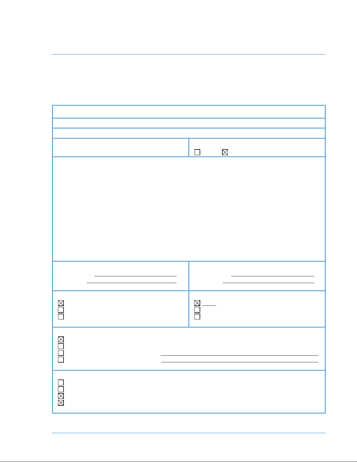
Table 2-1 provides a Device Profile Document in the standard format defined in the DNP3 subset
definition document. The table, in combination with the implementation table provided in Section 3 and
the point list tables provided in Section 5, provide a complete application configuration guide for including
the BE1-851E DNP protocol in any DNP environment.
Table 2-1. DNP3 Device Profile Document
Highest DNP Level Supported:
Notable objects, functions, and/or qualifiers supported in addition to the highest DNP levels supported
(the complete list is described in DNP3 Implementation Table):
- For static (non-change-event) object requests, request qualifier codes 00 and 01(start-stop), 07
and 08 limited quantity), and 17 and 28(index) are supported in addition to request qualifier code
06 (no range - or all points).
- Static object requests sent with qualifiers 00,01,06,07, and 08, will be responded to with qualifiers
00 or 01.
- Static object requests sent with qualifiers 17 and 28 will be responded to with qualifiers 17 or 28.
- The read function code for object 102 (8-bit unsigned integer), variation 1, is supported.
- Time period when device requires time-synchronization from the master is configurable via object
41, point 22.
- Dead band for current analog inputs’ events is configurable via object 41, point 23.
- Control Relay Output Blocks may be operated as defined in Table 4 or Table 5. Table selection is
made via object 40/41, point 24.
Maximum Data Link Frame Size (octets):
Transmitted 292
Received 292
Maximum Data Link Re-tries:
None
Fixed at
Configurable
Device Function:
Maximum Application Fragment Size (octets):
Transmitted 2048
Received 1024
Maximum Application Layer Re-tries:
None
Fixed at
Configurable, range ______ to ______
Requires Data Link Layer Confirmation:
Never
Always
Sometimes If 'Sometimes', when?
Configurable If 'Configurable', how?
Requires Application Layer Confirmation:
Never
Always (not recommended)
When reporting Event Data (Slave devices only)
When sending multi-fragment responses (Slave devices only)
9289900792 Rev C BE1-851E DNP Protocol 2-1
Page 12
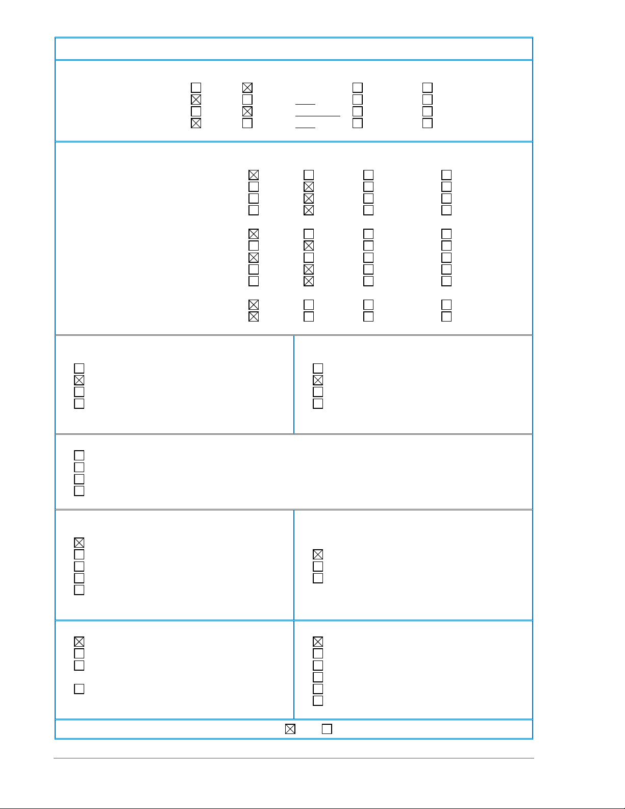
DEVICE PROFILE DOCUMENT
Timeouts while waiting for:
Data Link Confirm None Fixed at 3000 ms Variable Configurable
Complete Appl. Fragment None Fixed at Variable Configurable
Application Confirm None Fixed at 5000 ms Variable Configurable
Complete Appl. Response None Fixed at Variable Configurable
Sends/Executes Control Operations:
WRITE Binary Outputs Never Always Sometimes Configurable
SELECT/OPERATE Never Always Sometimes Configurable
DIRECT OPERATE Never Always Sometimes Configurable
DIRECT OPERATE - NO ACK Never Always Sometimes Configurable
Count > 1 Never Always Sometimes Configurable
Pulse On Never Always Sometimes Configurable
Pulse Off Never Always Sometimes Configurable
Latch On Never Always Sometimes Configurable
Latch Off Never Always Sometimes Configurable
Queue Never Always Sometimes Configurable
Clear Queue Never Always Sometimes Configurable
Reports Binary Input Change Events when no
specific variation requested (Slave Only):
Never
Only time-tagged
Only non-time-tagged
Configurable to send both, one or the other
(attach explanation)
Master Expects Binary Input Change Events:
Never
Either time-tagged or non-time-tagged for a single event
Both time-tagged and non-time-tagged for a single event
Configurable (attach explanation)
Sends Unsolicited Responses
(Slave Only):
Never
Configurable (attach explanation)
Only certain objects
Sometimes (attach explanation)
ENABLE/DISABLE UNSOLICITED
Function codes supported
Default Counter Object/Variation:
No Counters Reported
Configurable (attach explanation)
Default Object
Default Variation
Point-by-point list attached
Reports time-tagged Binary Input Change Events
when no specific variation requested:
Never
Binary Input Change With Time
Binary Input Change With Relative Time
Configurable (attach explanation)
Sends Static Data in Unsolicited Responses
(Slave Only):
Never
When Device Restarts
When Status Flags Change
No other options are permitted.
Counters Roll Over at:
No Counters Reported
Configurable (attach explanation)
16 Bits
32 Bits
Other Value:
Point- by-point list attached
Sends Multi-Fragment Responses (Slave Only): Yes No
2-2 BE1-851E DNP Protocol 9289900792 Rev C
Page 13

SECTION 3 • IMPLEMENTATION TABLE
Object
Variation
17,28 (index)
17,28 (index)
default variation)
06 (no range)
06 (no range)
see note 1)
06 (no range)
00,01 (start- stop)
17,28 (index)
see note 1)
00,01 (start- stop)
17,28 (index)
6 (dir op Noack)
00,01 (start-stop)
00,01 (start- stop)
17,28 (index)
00,01 (start- stop)
17,28 (index)
00,01 (start- stop)
17,28 (index)
see note 1)
00,01 (start- stop)
17,28 (index)
DNP Implementation Table
Table 3-1 identifies which object variations, function codes, and qualifiers the BE1-851E DNP supports in
both request messages and in response messages.
Static (non-change-event) object requests sent with qualifiers 00, 01, 06, 07, or 08 will be responded to
with qualifiers 00 or 01. Static object requests sent with qualifiers 17 or 28 will be responded to with
qualifiers 17 or 28.
Change-event objects are always responded to with qualifiers 17 and 28.
Table 3-1. BE1-851E DNP Implementation Table
OBJECT
No.
1 0 Binary Inputs - (Variation 0 is
1 1
2 0 Binary Input Change
2 1 Binary Input Change without
2 2
10 0 Binary Output - (Variation 0 is
10 2
No.
(default -
see note 1)
(default -
(default -
Description
used to request default
variation)
Single-Bit Binary Input 1 (read) 00,01 (start- stop)
(Variation 0 is used to request
time
Binary Input Change with time 1 (read)
used to request default
variation)
Binary Output Status 1 (read)
REQUEST
(BE1-851E will parse)
Function
Codes (dec)
1 (read) 00,01 (start- stop)
1 (read)
1 (read)
1 (read)
Qualifier Codes
(hex)
06 (no range)
07,08 (limited qty)
06 (no range)
07,08 (limited qty)
07,08 (limited qty)
07,08 (limited qty)
07,08 (limited qty)
06 (no range)
07,08 (limited qty)
06 (no range)
07,08 (limited qty)
RESPONSE
(BE1-851E will respond with)
Function
Codes (hex)
81
(response)
81
(response)
81
(response)
81 00,01 (start-stop)
Qualifier Codes
(hex)
00,01 (start-stop)
17,28 (index)
17,28 (index)
17,28 (index)
17,28 (index)
12 1 Control Relay Output Block 3 (select)
4 (operate)
5 (direct op)
30 0 Analog Input (Variation 0 is
30 1 32-Bit Analog Input With Flag 1 (read)
30 2 16-Bit Analog Input With Flag 1 (read)
30 3
(default -
used to request default
variation)
32-Bit Analog Input Without
Flag
1 (read)
1 (read)
07,08 (limited qty)
17,28 (index)
06 (no range)
07,08 (limited qty)
06 (no range)
07,08 (limited qty)
06 (no range)
07,08 (limited qty)
06 (no range)
07,08 (limited qty)
81 echo of request
81(response) 00,01 (start-stop)
17,28 (index)
81 00,01 (start-stop)
17,28 (index)
81 00,01 (start-stop)
17,28 (index)
81 00,01 (start-stop)
17,28 (index)
9289900792 Rev C BE1-851E DNP Protocol 3-1
Page 14

OBJECT
Object
Variation
00,01 (start- stop)
17,28 (index)
default variation)
06 (no range)
06 (no range)
time
06 (no range)
06 (no range)
07,08 (limited qty)
06 (no range)
07,08 (limited qty)
00,01 (start-stop)
17,28 (index)
00,01 (start-stop)
17,28 (index)
see note 1)
00,01 (start-stop)
17,28 (index)
6 (dir op noack)
00,01 (start-stop)
6 (dir op noack)
00,01 (start-stop)
00,01 (start-stop)
17,28 (index)
06 (no range or all)
06 (no range or all)
07,08 (limited qty)
06 (no range or all)
07,08 (limited qty)
06 (no range or all)
07,08 (limited qty)
00 (start-stop)
(index must=7)
00,01 (start- stop)
17,28 (index)
(See Note 3)
(See Note 3)
restart)
No Object (function code only)
23 (delay meas)
No.
30 4 16-Bit Analog Input Without
No.
Description
Flag
REQUEST
(BE1-851E will parse)
Function
Qualifier Codes
Codes (dec)
1 (read)
06 (no range)
07,08 (limited qty)
(hex)
RESPONSE
(BE1-851E will respond with)
Function
Codes (hex)
81 00,01 (start-stop)
Qualifier Codes
(hex)
17,28 (index)
32 0 Analog Change Event
32 1
(default -
see note 1)
32 2 16-Bit Analog Input without
32 3 32-Bit Analog Input with time 1 (read)
32 4 16-Bit Analog Input with time 1 (read)
40 0 Analog Output Status -
40 1 32-bit Analog Output Status 1 (read)
40 2
(default -
41 1 32-bit Analog Output Block 3 (select)
(Variation 0 is used to request
32-Bit Analog Input without
time
(Variation 0 is used to request
default variation)
16-bit Analog Output Status 1 (read)
1 (read)
1 (read)
1 (read)
1
4 (operate)
5 (direct op)
07,08 (limited qty)
07,08 (limited qty)
07,08 (limited qty)
06 (no range)
07,08 (limited qty)
06 (no range)
07,08 (limited qty)
06 (no range)
07,08 (limited qty)
07,08 (limited qty)
17,28 (index)
81 17,28 (index)
81 17,28 (index)
81 17,28 (index)
81 17,28 (index)
81 00,01 (start-stop)
17,28 (index)
81 00,01 (start-stop)
17,28 (index)
81 echo of request
41 2 16-bit Analog Output Block 3 (select)
4 (operate)
5 (direct op)
50 1 Time and Date 1 (read)
2 (write)
60 1 Class 0 Data (Note 1) (Note 4) 1 (read)
60 2 Class 1 Data 1 (read)
60 3 Class 2 Data 1 (read)
60 4 Class 3 Data 1 (read)
80 1 Internal Indications 2 (write)
102 1 8-Bit Unsigned Integer (Note
2)
No Object(function code only)
No Object(function code only)
1 (read)
13 (cold restart)
14 (warm
07,08 (limited qty)
17,28 (index)
06 (no range or all)
07 (limited qty=1)
08 (limited qty)
06 (no range)
07,08 (limited qty)
81 echo of request
81 00,01 (start-stop)
17,28 (index)
81
81
81
81
81(response) 00,01 (start-stop)
17,28 (index)
3-2 BE1-851E DNP Protocol 9289900792 Rev C
Page 15

Notes for Table 3-1:
1. A Default variation refers to the variation responded to when variation 0 is requested and/or in class
0, 1, 2, or 3 scans.
2. Object 102 is not included in Class 0 poll response.
3. A cold restart is implemented as a warm restart - the DNP process is restarted.
4. In Class 0 are included all Binary Inputs (object 1), and a selected set of Analog Inputs (object 30).
Binary Output Status points and Analog Output Status points are not included in Class 0.
9289900792 Rev C BE1-851E DNP Protocol 3-3
Page 16

3-4 BE1-851E DNP Protocol 9289900792 Rev C
Page 17

SECTION 4 • CONFIGURATION PARAMETERS
DNP Configuration Parameters
These paragraphs describe configuration settings that may be verified/changed from the BE1-851E front
panel or using ASCII protocol commands.
Relay Style Number
BE1-851E relays that support the DNP protocol must have a Style Number that contains the number 3 for
the Com2 RS-485 option. This can be verified by reading the relay Style Number via the front
communication port using the RG-VER ASCII command. (Reference the BE1-851E Instructional Manual,
part number 9289900790).
Example:
>rg-ver
Model Number: BE1-851E
Style Number: H5N1H3N
App Program: VER x.xx.xx xx/xx/xx
Boot Program: VER x.xx
Serial Number:H12345678
BE1-851E Slave Address
BE1-851E relays support DNP through the rear RS-485 communication port, which is communication port
2 (COM2). This port supports Baud Rates: 1200, 2400, 4800, 9600, and 19200, and the default Baud
Rate is 9600.
DNP Slave IED Address Range is from 0 to 65534. Address 65535 (hex FFFF) is used to broadcast
messages to all devices. The communication address can be set by the SG-COM ASCII command. For
more information about changing the relay parameters, refer to the BE1-851E Instructional Manual, part
number 9289900790.
Example: Set the BE1-851E address to be 125, and baud rate to be 9600.
(In the following example, the operator’s commands are in bold.)
>a=<global_password> <enter> //enter global password
>ACCESS GRANTED: GLOBAL
> sg-com2=9600,a125(enter)
>exit (enter)
>SAVE CHANGES (Y/N/C) ?
>y <enter>
>CHANGE COMM PARAMETERS
>
To verify port address, enter command
>sg-com2(enter)
>SG-COM2=9600, A125, P0,R1,X0
9289900792 Rev C BE1-851E DNP Protocol 4-1
Page 18

4-2 BE1-851E DNP Protocol 9289900792 Rev C
Page 19

SECTION 5 • POINT LIST
TABLE OF CONTENTS
SECTION 5 • POINT LIST ........................................................................................................................ 5-1
Binary Input Points ................................................................................................................................. 5-1
Binary Input Points ............................................................................................................................. 5-1
Binary Output Status Points and Control Relay Output Jacks ............................................................... 5-4
Appendix for Binary Output Status Points and Control Relay Output Blocks ........................................ 5-6
Analog Inputs ......................................................................................................................................... 5-8
Analog Inputs ..................................................................................................................................... 5-8
Negative Sequence Fault Current ...................................................................................................... 5-9
Analog Output Status Points and Control Blocks ................................................................................ 5-14
Analog Output Status Points ............................................................................................................ 5-15
Analog Output Blocks ....................................................................................................................... 5-15
8-Bit Unsigned Integer, Object 102 ...................................................................................................... 5-18
8-Bit Unsigned Integer ...................................................................................................................... 5-18
Tables
Table 5-1. Binary Input Points ................................................................................................................... 5-1
Table 5-2. Binary Output Status Points and Control Relay Output Blocks................................................ 5-4
Table 5-3. Appendix for Binary Output Status Points and Control Relay Output Blocks .......................... 5-6
Table 5-4. Analog Inputs ........................................................................................................................... 5-8
Table 5-5. Target Format ......................................................................................................................... 5-12
Table 5-6. Reclose Status Format ........................................................................................................... 5-13
Table 5-7. Breaker Failure Status Format ............................................................................................... 5-14
Table 5-8. System Status ........................................................................................................................ 5-14
Table 5-9. Analog Output Status Points and Control Blocks ................................................................... 5-15
Table 5-10. Alarm Status ......................................................................................................................... 5-16
Table 5-11. Relay Trouble Status Format ............................................................................................... 5-17
Table 5-12. Object 102, 8-Bit Unsigned Integer Points ........................................................................... 5-18
9289900792 Rev C BE1-851E DNP Protocol i
Page 20

ii BE1-851E DNP Protocol 9289900792 Rev C
Page 21

SECTION 5 • POINT LIST
Change Event
none)
0
50T Phase A Tripped
1
1 50T Phase B Tripped
1
2
50T Phase C Tripped
1
3
150T Phase A Tripped
1
4
150T Phase B Tripped
1
5 150T Phase C Tripped
1
6 50T Neutral Tripped
1
7 150T Neutral Tripped
1
8
50T Negative Sequence Tripped
1
9 150T Negative sequence Tripped
1
10
Breaker Failure Tripped
1
11
51 Phase A Tripped
1
12
51 Phase B Tripped
1
13
51 Phase C Tripped
1
14
51 Neutral Tripped
1
15
51Q Tripped
1
16
62 1
17
162 1
18
43 1
19
143 1
20
243 1
21
343 1
22
79 Close Signal
1
23
79 Running
1
24
79 Locked Out
1
25
79 Reclose Fail
1
Binary Input Points
Binary Input changes are scanned every four milliseconds. Events are pending in the Slave application
buffer until the Master device sends conformation that response with pending events was received. Table
5-1 describes the binary input points.
Table 5-1. Binary Input Points
Binary Input Points
Static Object Number: 1
Change Event Object Number: 2
Request Function Codes Supported: 1 (read)
Static Variation Reported When Variation 0 Requested: 1 (Binary Input Without Status)
Change Event Variation Reported When Variation 0 Requested: 2 (Binary Input Change With Time)
Point
Index
Description
Assigned
Class (1,2,3 or
Notes
9289900792 Rev C BE1-851E DNP Protocol 5-1
Page 22

Point
Change Event
none)
26
79 Sequence Control Block
1
27
Input Contact 1
1
28
Input Contact 2
1
29
Input Contact 3
1
30
Input Contact 4
1
31
101 Trip
1
32
101 Close
1
33
101 Slip Contact ( 0= Breaker Tripped, 1 = Breaker Is Closed )
1
34
Logic Alarm
1
35
Major Alarm
1
36
Minor Alarm
1
37
Output Trip Coil Monitor
1
38
Setting Group 0 Active
1
39
Setting Group 1 Active
1
40
Setting Group 2 Active
1
41
Setting Group 3 Active
1
Hardware Output Status (points 42 - 49)
42
Output A
1
43
Output 1
1
44
Output 2
1
45
Output 3
1
46
Output 4
1
47
Output 5
1
48
Output 6
1
49
Output 7
1
Programmable Alarms (points 50 - 75) See Note 2
50
Trip Circuit Monitor Alarm
1
51
Breaker Fail Alarm
1
52
Recloser Fail Alarm
1
53
Recloser Lockout
1
54
Breaker Alarm 1
1
55
Breaker Alarm 2
1
56
Breaker Alarm 3
1
57
P Demand Alarm
1
58
N Demand Alarm
1
59
Q Demand Alarm
1
60
Group Override (0=Local Control, 1= Group Override)
1
61
Sys I/O Delay Alarm
1
62
Communication Error Alarm
1
Index
Description
Assigned
Class (1,2,3 or
Notes
5-2 BE1-851E DNP Protocol 9289900792 Rev C
Page 23

Point
Change Event
none)
63
Clock Error Alarm
1
64
MPU Reset Alarm
1
65
Settings Changed
1
66
EEPROM Non fatal error
1
67
An override is active in one or more outputs
1
68
Loss of IRIG
1
69
Setting Group Change Active alarm
1
70
VO13 Logic Alarm
1
71
VO14 Logic Alarm
1
72
VO15 Logic Alarm
1
73
FLT RPT Time Out
1
74
Logic NONE alarm
1
75
Settings Changes Lost due to Access Time Out
1
Relay Trouble Alarms (points 76 - 80)
76
EEPROM Read/Write Fatal Error
1
77
Analog problem detected
1
78
Relay not calibrated or calibration checksum error
1
79
SETTING defaults loaded
1
80
Calibration defaults loaded
1
State Of Fault Trigger Logic Expressions (points 81 - 83) See Note 3
81
Pick Up trigger expressions state (1=TRUE,0 =FALSE)
1
82
Trip trigger logic expressions state (1=TRUE,0 =FALSE)
1
83
Logic trigger expressions state (1=TRUE,0 =FALSE)
1
84
1: New Fault triggered. Fault data will be saved as the “Most
0: The “Most Recent Fault Summary Report “available.
1
1
Index
Description
Assigned
Class (1,2,3 or
Notes
Recent Fault Summary Report”, and available when this point
becomes 0.
Notes for Table 5-1:
1. The time stamp from transition 0 to 1 is a fault trigger time (equal to the time in the most recent
Fault Summary Report).
The time stamp from transition 1 to 0 is the time since fault data of the most recent fault is
available (see object 30 points from 17 to 36).
Total count of transitions from 0 to 1, reports the number of faults, which have occurred between
two reporting. The missed Fault Summary Report Data can be retrieved through the Selected
Fault Summary Report (see object 30, points from 52 to 71).
2. Any alarm from this Programmable Alarms group may be declared as a major, minor, or logic
alarm. Refer to ASCII Serial Command SG-LGC, SA-MAJ, and SA-MIN.
3. Refer to ASCII Serial Command: SG-TRIGGER=<trip>,<pu>,<logic>.
9289900792 Rev C BE1-851E DNP Protocol 5-3
Page 24

Binary Output Status Points and Control Relay Output Jacks
Point
Index
0
Hardware Output A State
Latch On: Set Output x to state 1
1
Hardware Output 1 State
2
Hardware Output 2 State
3
Hardware Output 3 State
4
Hardware Output 4 State
5
Hardware Output 5 State
6
Hardware Output 6 State
7
Hardware Output 7 State
8
All Hardware Outputs State
9
Hardware Output A Local Control
Latch On: Set Hardware Output x to relay
10
Hardware Output 1 Local Control
11
Hardware Output 2 Local Control
12
Hardware Output 3 Local Control
13
Hardware Output 4 Local Control
14
Hardware Output 5 Local Control
15
Hardware Output 6 Local Control
16
Hardware Output 7 Local Control
17
All Hardware Outputs Local Control
18
43 Selector Switch Status
Latch On: Set x Selector Switch to 1
250 ms).
19
143 Selector Switch Status
20
243 Selector Switch Status
21
343 Selector Switch Status
22
Setting Group 0
Latch On: Select Group x to be Active
23
Setting Group 1
24
Setting Group 2
25
Setting Group 3
Table 5-2 lists both the Binary Output Status Points (Object 10) and the Control Relay Output Blocks
(Object 12). It is important to note that Binary Output Status Points are not included in Class 0.
Table 5-2. Binary Output Status Points and Control Relay Output Blocks
Binary Output Status Points:
Object Number: 10
Variations supported: 2
Request Function Codes supported: 1 (read)
Default Variation reported when variation 0 requested: 2 (Binary Output Status)
Control Relay Output Blocks
Object Number: 12
Variations supported: 1
Request Function Codes supported: 3(select), 4(operate), 5(direct operate), 6 (direct operate, noack)
Description Control Codes And Their Description
Latch Off: Set Output x to state 0
Pulse On: Pulse output x to opposite of
current state then restore to
previous state ( pulsed output
is active 200 to 250 ms)
5-4 BE1-851E DNP Protocol 9289900792 Rev C
logic
Latch Off: Set x Selector Switch to 0
Pulse On: Pulse x Selector Switch state
to opposite of the current state
then restore to previous state
(pulsed input is active 200 to
Page 25

Point
Index
Description Control Codes And Their Description
26
Local Setting Group Control Switch
Latch On: Return Setting Group Control
to relay local logic
27
101 Virtual Breaker Control Switch
Close: Close Breaker (changes 101C
from 0 to 1 for 200 ms)
Binary Input from 0 to 1 for 200
ms )
Trip: Trip Breaker (changes 101T
Notes for Table 5-2:
1. Read of Points
- Reads of points from 0 to 7, 9 to 16, and 18 to 26 return the current state of corresponding
point.
- Reads of points from 8, 17, and 27 always return zero.
2- The following restrictions should be observed when using object 12 to control the points listed in
Table 5-1.
• The Control Code field of object 12 is parsed the following way:
- If the Control Code is NULL, then the command will be accepted without any action being
taken.
- If Queue, and Clear sub-fields are not zero, the returned Control Status is 4 (Control
operation not supported).
- A Code sub-field of “Pulse On” (1) in combination with a value in the Trip/Close sub-field
form a “Trip” or “Close” value. A “Trip” value consists of a “PULSE ON” (1) in the Code
sub-field and a 2 in the Trip/Close sub-field. This results in a value of 81(hex) in the
Control Code field. A “Close” value consists of a “PULSE ON” (1) in the Code sub-field
and a 1 in the Trip/Close sub-field. This results in a value of 41 (hex) in the Control Code
field.
3. Valid Control Code values are:
- 0x00 = No action will be taken.
- 0x01 = Pulse output to opposite of current state, and then restore to previous state. Pulsed
output is active 200 to 250 ms.
- 0x03 = Latch On
- 0x04 = Latch Off
- 0x41 = Close (Breaker Close)
- 0x81 = Trip (Breaker Open)
All operations not defined above are invalid and will be rejected. If the Control Code is legal, but not
supported for the requested point, the Status Return value is “Control operation not supported for this
point” (value 4).
- The Count, OnTime and OffTime fields are ignored.
- Arm timer value for all Select/Operate operations is 30 seconds.
It is important to notice that any control function may be rejected because of the relay internal state.
When this happens, the Status Return value is “Request not accepted because of hardware
problems” (value 6). One of the reasons for the rejection may be that that point Logic Function Block
has the Logic (Control) Mode disabled.
For example: Control functions for the hardware output points (points 0 to 13) will be rejected if the
Output Control for all hardware outputs is disabled.
The Logic (Control) Mode of any object 12 point can be changed (enabled/disabled) via the specific
point of object 41 (Analog Output Control Blocks). Refer to Analog Output Status Points and Analog
Output Control Block points from 0 to 6.
9289900792 Rev C BE1-851E DNP Protocol 5-5
Page 26

Appendix for Binary Output Status Points and Control Relay Output
Binary Output Status Points:
Complementary
Function Index
Hardware Output A -
Latch control
0x03(Latch On/NUL) or
Hardware Output 1- Latch
control
Hardware Output 2-
Latch control
Hardware Output 3 - -
Latch control
Hardware Output 4 -
Latch control
Hardware Output 5 -
Latch control
Hardware Output 6 -
Latch control
Hardware Output 7 -
Latch control
All Hardware Outputs’ -
Blocks
To enable Master which can support only Trip and Close commands to control BE1-851E Control Relay
Output Block points, second way of controlling Control Relay Output Blocks is added as presented in
Table 5-3.
User can select old (legacy) Control Relay Output Blocks (Table 5-2) or a new (Table 5-3) via DNP object
41 point 24. Selection stays remembered in non-volatile memory. When Table 5-2 is selected, object 40,
point 24 has value 1. When Table 5-3 is selected, object 40, point 24 has value 2. When selecting specific
Control Relay Output Blocks table, object 41, point 24 must be set to 1 or 2 via function codes
select/operate or only direct operate or direct operate, noack.
Notes:
- Old Control Relay Output Blocks (Table 5-2) has 27 points while new Control Relay Output
Blocks (Table 5-3) has 38. The additional 11 points are added as single function points to support
only pulsing control. New Control Relay Output Blocks (Table 5-3) has only complementary or
single function indices and is DNP compliant.
- Reading values of points 0 to 27 are the same in the both Control Relay Output Blocks tables.
Reading values of points 28 to 40 in the new Control Relay Output Blocks (Table 5-3) are the
same as for points 0 to 8, and points 37 to 40 have the same reading values as points 18 to 21.
Table 5-3. Appendix for Binary Output Status Points and Control Relay Output Blocks
Object Number: 10
Variations supported: 2
Request Function Codes supported: 1(read)
Default Variation reported when variation 0 requested:2(Binary Output Status)
Control Relay Output Blocks
Object Number: 12
Variations supported: 1
Request Function Codes supported: 3(select), 4(operate),5(direct operate), 6(direct operate, noack)
Point
Index
0
1
2
3
4
5
6
7
8
Latch control
Description
(C) or
Single (S)
C
Permitted Codes
0x41(PulseOn/Close) sets output to
state 1
0x04 (Latch Off/NUL) or
0x81(PulseOn/Trip) sets output to state 0
5-6 BE1-851E DNP Protocol 9289900792 Rev C
Page 27

Point
Complementary
Function Index
Hardware Output A Local
Control
0x03(Latch On/NUL) or
Hardware Output 1 Local
Control
Hardware Output 2 Local
Control
Hardware Output 3 Local
Control
Hardware Output 4 Local
Control
Hardware Output 5 Local
Control
Hardware Output 6 Local
Control
Hardware Output 7 Local
Control
All Hardware Outputs’ Local
Control
43 Selector Switch Status -
Latch control
0x03(Latch On/NUL) or
143 Selector Switch Status -
Latch control
243 Selector Switch Status -
Latch control
343 Selector Switch Status -
Latch control
22
Setting Group 0
S
0x03(Latch On/NUL) or
23
Setting Group 1
24
Setting Group 2
25
Setting Group 3
Local Setting Group Control
0x03(Latch On/NUL) or
Group Control to relay local logic
101 Virtual Breaker Control
Switch
0x41(PulseOn/Close) Close breaker
0x81(PulseOn/Trip) Trip breaker
Hardware Output A - Pulse
Control
0x81(Pulse On/Trip) or
Hardware Output 1 - Pulse
Control
Hardware Output 2 -Pulse
Control
Hardware Output 3 -Pulse
Control
Hardware Output 4 -Pulse
Control
Index
Description
(C) or
Single (S)
Permitted Codes
9
10
11
12
13
14
15
16
17
18
19
20
S
C
0x41(PulseOn/Close) sets output to
relay logic
0x41(PulseOn/Close) sets Selector
Switch to 1
0x04 (Latch Off/NUL) or
0x81(PulseOn/Trip) sets Selector Switch
to 0
21
26
Switch S
27
28
29
30
31
32
C
S
0x41(PulseOn/Close) selects group
to be active
0x41(PulseOn/Close) returns Setting
0x01(Pulse On/NUL)
Pulse output / Selector switch to opposite
of current state then restore
to previous state(pulsed output is active
200 to 250 ms)
9289900792 Rev C BE1-851E DNP Protocol 5-7
Page 28

Point
Complementary
Function Index
Hardware Output 5 - Pulse
Control
Hardware Output 6 - Pulse
Control
Hardware Output 7 - Pulse
Control
All Hardware Outputs’ Pulse Control
43 Selector Switch - Pulse
Control
143 Selector Switch -Pulse
Control
243 Selector Switch - Pulse
Control
343 Selector Switch - Pulse
Control
Change Event
(1, 2, 3, or none)
0
Primary Phase A Current Magnitude
2
1, 1∗
1
Primary Phase B Current Magnitude
2
1, 1∗
2
Primary Phase C Current Magnitude
2
1, 1∗
3
Neutral Current Magnitude
2
1, 1∗
4
Primary Negative Sequence Current Magnitude
2
1, 1∗
Index
Description
33
34
35
36
37
38
39
40
Analog Inputs
(C) or
Single (S)
Permitted Codes
The following table lists Analog Inputs (Object 30/Object 32). It is important to note that 16-bit and 32-bit
variations of Analog Inputs, Analog Output Control Blocks, and Analog Output Statuses are transmitted
through DNP as signed numbers. Even for analog input points that are not valid as negative values, the
maximum positive representation for a 16-bit variation is <2
maximum positive representation is <2
31
-1> = 2,147,483,647.
15
-1> = 32,767. For a 32-bit variation the
It is important to note that all analog points are not reported in Class 0 (or any other class). These points
are from point 52 to point 116. They have “none” in the column for “Event Class Assigned To” as shown in
Table 5-4. They can be read from the BE1-851E as object 30, with any variation or qualifier implemented
for object 30.
Change events for analog inputs are reported in CURRENT mode (when a change is detected, the report
of the change contains the current value of the time of the report, - not the time the change was detected.
Table 5-4. Analog Inputs
Analog Inputs
Static Object Number : 30
Change Event Object Number : 32
Request Function Codes Supported: 1 (read)
Static Variation Reported When Variation 0 Requested: 3 (32-bit Analog Input without Flag)
Change Event Variation Reported When Variation 0 Requested: 1 (32-bit Analog Change Event without
Time)
Index Description
Assigned Class
Notes
5-8 BE1-851E DNP Protocol 9289900792 Rev C
Page 29

Index Description
Change Event
(1, 2, 3, or none)
117
3I0 Current Magnitude
2
1, 1∗
5
Present Demand Current - Phase A
2
1, 1∗
6
Present Demand Current - Phase B
2
1, 1∗
7
Present Demand Current - Phase C
2
1, 1∗
8
Present Neutral Demand Current (When SEF, 3I0 is used.)
2
1, 1∗
9
Present Negative Sequence Demand Current- Phase A
2
1, 1∗
10
Breaker Duty - Phase A
2
12
11
Breaker Duty - Phase B
2
12
12
Breaker Duty - Phase C
2
12
13
Breaker Operation Counter
2
13
14
BF Status
1
15
15
Latched Targets - part 1
1
21
16
Latched Targets - part 2
1
21
The Most Recent Fault Summary Report
17
Fault Number
1
2, 16
18
Fault Trigger Time Stamp - part 1; days
1
3, 16
19
Fault Trigger Time Stamp - part 2; ms
1
3, 16
20
Active Setting Group
1
4, 16
21
Trigger
1
5, 16
22
System Status - part 1
1
22
23
System Status - part 2
1
22
24
System Status - part 3
1
22
25
System Status - part 4
1
22
26
Targets - part 1
1
6, 16
27
Targets - part 2
1
6, 16
28
Reclose Status
1
7, 16
29
Fault Clearing Time
1
8, 16
30
Breaker Operate Time
1
9, 16
31
Number of Oscillographic Reports
1
10, 16
32
Phase A Fault Current
1
1, 16
33
Phase B Fault Current
1
1, 16
34
Phase C Fault Current
1
1, 16
35
Neutral Fault Current
1
1, 16
36
Negative Sequence Fault Current
1
1, 16
118
3I0 Fault Current
1
1, 16
Active Logic Name
37
1st character of Active Logic Name
3
16
38
2nd character of Active Logic Name
3
16
39
3rd character of Active Logic Name
3
16
40
4th character of Active Logic Name
3
16
Assigned Class
Notes
9289900792 Rev C BE1-851E DNP Protocol 5-9
Page 30

Index Description
Change Event
(1, 2, 3, or none)
41
5th character of Active Logic Name
3
16
42
6th character of Active Logic Name
3
16
43
7th character of Active Logic Name
3
16
44
8th character of Active Logic Name
3
16
Logic Function Blocks’ settings
45
Hardware Outputs’ Control Mode
3
17, 16
46
43 Aux Virtual Switch Logic Mode
3
18, 16
47
143 Aux Virtual Switch Logic Mode
3
18, 16
48
243 Aux Virtual Switch Logic Mode
3
18, 16
49
343 Aux Virtual Switch Logic Mode
3
18, 16
50
Setting Group Logic Mode
3
19, 16
51
101 Breaker Switch Control Mode
3
20, 16
Selected Fault Summary Report (See Note 14)
52
Fault Number
none
2
53
Fault Trigger Time Stamp - part 1; days
none
3
54
Fault Trigger Time Stamp - part 2; ms
none
3
55
Active Setting Group
none
4
56
Trigger
none
5
57
System Status - part 1
none
22
58
System Status - part 2
none
22
59
System Status - part 3
none
22
60
System Status - part 4
none
22
61
Targets - part 1
none
6
62
Targets - part 2
none
6
63
Reclose Status
none
7
64
Fault Clearing Time
none
8
65
Breaker Operate Time
none
9
66
Number of Oscillographic Reports
none
10
67
Phase A Fault Current
none
1
68
Phase B Fault Current
none
1
69
Phase C Fault Current
none
1
70
Neutral Fault Current
none
1
71
Negative Sequence Fault Current
none
1
119
3I0 Fault Current
none
1
Demand Currents Historical Data
Peak Demand Current Since Reset
72
Phase A current
none
1
73
Phase A Time Stamp - part 1; days
none
11
74
Phase A Time Stamp - part 2; ms
none
11
75
Phase B current
none
1
Assigned Class
Notes
5-10 BE1-851E DNP Protocol 9289900792 Rev C
Page 31

Index Description
Change Event
(1, 2, 3, or none)
76
Phase B Time Stamp - part 1; days
none
11
77
Phase B Time Stamp - part 2; ms
none
11
78
Phase C
none
1
79
Phase C Time Stamp - part 1; days
none
11
80
Phase C Time Stamp - part 2; ms
none
11
81
Neutral (When SEF, 3I0 is used.)
none
1
82
Neutral Time Stamp - part 1 ; days
none
11
83
Neutral Time Stamp - part 2; ms
none
11
84
Negative Sequence
none
1
85
Negative Sequence Time Stamp - part 1; days
none
11
86
Negative Sequence Time Stamp - part 2; ms
none
11
Today’s Peak Demand Current
87
Phase A current
none
1
88
Phase A Time Stamp - part 1; days
none
11
89
Phase A Time Stamp - part 2; ms
none
11
90
Phase B current
none
1
91
Phase B Time Stamp - part 1; days
none
11
92
Phase B Time Stamp - part 2; ms
none
11
93
Phase C
none
1
94
Phase C Time Stamp - part 1; days
none
11
95
Phase C Time Stamp - part 2; ms
none
11
96
Neutral (When SEF, 3I0 is used.)
none
1
97
Neutral Time Stamp - part 1; days
none
11
98
Neutral Time Stamp - part 2; ms
none
11
99
Negative Sequence
none
1
100
Time Stamp - part 1; days
none
11
101
Time Stamp - part 2; ms
none
11
Yesterday’s Peak Demand Current
102
Phase A current
none
1
103
Phase A Time Stamp - part 1; days
none
11
104
Phase A Time Stamp - part 2; ms
none
11
105
Phase B current
none
1
106
Phase B Time Stamp - part 1; days
none
11
107
Phase B Time Stamp - part 2; ms
none
11
108
Phase C
none
1
109
Phase C Time Stamp - part 1; days
none
11
110
Phase C Time Stamp - part 2; ms
none
11
111
Neutral (When SEF, 3I0 is used.)
none
1
112
Neutral Time Stamp - part 1; days
none
11
113
Neutral Time Stamp - part 2; ms
none
11
Assigned Class
Notes
9289900792 Rev C BE1-851E DNP Protocol 5-11
Page 32

Index Description
Change Event
(1, 2, 3, or none)
114
Negative Sequence
none
1
115
Negative Sequence Time Stamp - part 1; days
none
11
116
Negative Sequence Time Stamp - part 2; ms
none
11
Value/Bit Mask
Part 1 Description
Part 2 Description
0001h
50TA
51A
0002h
50TB
51B
0004h
50TC
51C
0008h
50TN
51N
0010h
50TQ
51Q
0020h
62
spare
0040h.
162
spare
0080h
BF
spare
0100h
150TA
151A
Notes for Table 5-4:
1. All current values are in primary centiamps (value 1 represents 0.01 ampere). When SEF, neutral
current (value 1 represents 0.0001 ampere).
1∗. Current analog input point generates an analog event if the current value is bigger than the
“previous current value plus dead band”, or smaller than the “previous current value minus dead
band”.
Dead band for an analog event is configurable via DNP Analog Output point 23, “Current Dead
band”. The default value for the dead band is set to be ±2.5% of the primary nominal current. For
more information about dead band configuration, see the description in the following paragraphs
Analog Output Status Points and Control Blocks, point 23, Note 14 for Table 5-12.
2. Fault Number range is from 1 to 255. For example, after 255, fault number is going to be 1.
3. This time is a fault trigger time presented in relay’s internal format: part 1 contains days (1 to
65535), and part 2 contains milliseconds (1 to 86,400,000) since January 1, 1984. This time is
equal to the time of Binary Input Event “New Fault triggered” (transition from 0 to 1).
Notice that the Binary Input Event time stamp is presented in DNP time stamp format, since
January 1, 1970.
4. Active setting group at time of fault (0 or 1 or 2 or 3).
5. Event type (value is 1, 2, 4, 8, or 16) reports the classification assigned to the fault event. Fault
events are classified into five categories.
a. Breaker Failure (Event Type value is 1): A fault was initiated by the pickup expression and
the breaker failure trip became true before fault was cleared.
b. Trip (Event Type value is 2): A fault was initiated by overcurrent pickup and the relay tripped
to clear the fault.
c. Logic (Event Type value is 4): A fault was detected as defined by the relay logic trigger
expression, but no fault was detected as defined by the pickup expression.
d. Pickup (Event Type value is 8): A fault was initiated by the pickup expression but the relay
never tripped indicating that the fault was cleared by some other device.
e. RF=TRIG (Event Type value is 16): A Fault was triggered by the ASCII command
RF=TRIGGER received via the front panel communication Serial Port or rear RS-232 port.
6. Targets-part 1 and targets-part 2 are bit-mapped variables that report what targets were logged to
the fault report between the time that the trip expression became true until the end of the fault. See
Table 5-5 for the target format.
Table 5-5. Target Format
Assigned Class
Notes
5-12 BE1-851E DNP Protocol 9289900792 Rev C
Page 33

Value/Bit Mask
Part 1 Description
Part 2 Description
0200h
150TB
151B
0400h
150TC
151C
0800h
150TN
151N
1000h
150TQ
151Q
2000h
spare
spare
4000h
spare
spare
8000h
spare
spare
7. Reclose Status are bit mapped variables that report the state of the recloser shot counter prior to
Value/Bit Mask
Description
0001h
Recloser active
0002h
Recloser Reset
0004h
Reclose Max Timing
0008h
Reclose Failure
0010h
Reclose Lockout
0020h
Reclose Wait
0040h
Reclose Enable
0080h
Reclose Max Enable
0100h
Reclose Fail Enable
0200h
Reclose Wait Enable
0400h
Reclose Timing 1
1000h
Reclose Timing 2
2000h
Reclose Timing 3
4000h
Reclose Timing 4
8000h
Reclose Timing Fail
the fault that triggered the fault (see format in Table 5-6).
Table 5-6. Reclose Status Format
9289900792 Rev C BE1-851E DNP Protocol 5-13
8. Fault Clearing Time is time in milliseconds from 0 to 60,000.
9. Breaker Operate Time is time in milliseconds from 0 to 60,000.
10. A number of recorded oscillographic records per fault (read value of this point) can be 1 or 2.
11. Time presented in relay internal format: part 1 contains days (1 to 65,535) and part 2 milliseconds
(1 to 86,400,000) since January 1, 1984.
12. Point represents assigned phase accumulated breaker pole duty as a centipercent of the
maximum duty (DMAX) that the breaker contacts can withstand before they need service.
2
Breaker Accumulated Duty for Phase A, B, and C is calculated as ΣI or ΣI
. This is defined by the
Breaker Contact Duty Operation Mode 0/1/2 entered via the ASCII protocol command SB-DUTY.
DMAX is defined through the same SB-DUTY command (for more information, see the BE1-851E
Instruction Manual, Section 4, Protection and Control). Value range is from 0 to 20,000 where
20,000 represents 200% of DMAX. Delta of 20 centipercent will cause an event. This point can be
changed via object 41. See the paragraph for Analog Output Control Blocks, Note 9.
13. This is the number of recorded breaker operations (0 - 99,999). If the operations counter exceeds
99,999, the counter will wrap back to zero. This value can be changed via object 41, point 15 to
any value from 0 to 99,999. Delta of 1 will cause an event.
14. Selected Fault Summary Report contains fault data for fault number defined by the value of Analog
Output Status (object 40) point 21 “Fault Number for Selected Fault Summary Report”.
Page 34

15. BF status is the bit mapped variable with format as described in Table 5-7. Delta of 1 deviation will
Value / Bit Mask (hex)
Description
0001
Breaker Operation Control State {1=Breaker Operation Enabled;
0= Breaker Operation Disabled}
0002
Breaker State {1=Breaker Opened; 0= Breaker Closed}
Value/Bit Mask (hex)
Part 1 Description
Part 2 Description
Part 3 Description
Part 4 Description
0001h
50 Phase Tripped
BF Picked Up
Virtual Output A
Input Contact 1
0002h
150 Phase Tripped
51 Phase Picked Up
Virtual Output 1
Input Contact 2
0004h
50 Neutral Tripped
51 Neutral Picked UP
Virtual Output 2
Input Contact 3
0008h
150 Neutral Tripped
51 Q Picked Up
Virtual Output 3
Input Contact 4
0010h
50Q Tripped
62 Tripped
Virtual Output 4
101 TRIP
0020h
150Q Tripped
162 Tripped
Virtual Output 5
101 CLOSE
0040h.
BF Tripped
43
Virtual Output 6
101 SLIP CONTACT
0080h
51 Phase Tripped
143
Virtual Output 7
HMI Reset Key
0100h
51 Neutral Tripped
243
Virtual Output 8
Logic Alarm
0200h
51 Q Tripped
343
Virtual Output 9
Major Alarm
0400h
50 Phase Picked Up
79 Close
Virtual Output 10
Minor Alarm
0800h
150 Phase Picked Up
79 Enabled
Virtual Output 11
Output 1 Trip Coil Monitor
1000h
50 Neutral Picked Up
79 Lockout
Virtual Output 12
Setting Group 0
2000h
150 Neutral Picked Up
79 Reclose Fail
Virtual Output 13
Setting Group 1
4000h
50Q Picked Up
79 Block Output
Virtual Output 14
Setting Group 2
8000h
150Q Picked Up
Always False (zero)
Virtual Output 15
Setting Group 3
cause en event.
Table 5-7. Breaker Failure Status Format
16. Delta of 1 bit (any change) will cause an event.
17. Read values for Hardware Output Control is 1 = Enabled, and 0=Disabled.
18. Read values for x43 AUX Virtual Switch Logic Mode are 0 for Disabled, 1 = ON/OFF PULSE, 2 =
ON/OFF, and 3= OFF/MOMENTARY ON.
19. Read values for Setting Group Mode is 0= Disabled, 1=discrete select, and 2= binary select.
Setting groups can be controlled via DNP object 12 if value is 1 or 2.
20. Read values for 101 Breaker Control Switch Mode is 0=Disabled and 1=Enabled.
21. Latched Targets Status format is described in Table 5-5 under Note 6 to Table 5-4. Delta of 1
deviation will cause an event. Latched Targets Status can be reset via object 41 point 7.
22. BE1-851E Relay System Status is represented as 4 part, 16-bit mapped variables. The four part
System Status is described in Table 5-8. (For more information, see the BE1-851E Instruction
Manual, Section 6, Reporting and Alarm Functions). Delta of 1 deviation will cause an event.
Table 5-8. System Status
Analog Output Status Points and Control Blocks
Table 5-9 lists both the Analog Status Points (Object 40) and the Analog Output Control Blocks (Object
41). It is important to note that Analog Output Status Points are not included into Class 0.
The Return Status Value for object 41 for all control operations may be 6 (hardware problem) due to a
value out of range, or a relay internal state. One of the reasons for rejection may be if another
communication port or front panel HMI is actively programming. For more information, see the BE1-851E
Instructional Manual, Section 10, Human-Machine Interface.
5-14 BE1-851E DNP Protocol 9289900792 Rev C
Page 35

Table 5-9. Analog Output Status Points and Control Blocks
Index
Description
Notes
0
Hardware Output Logic Control Mode
1,2
1
43 Aux Virtual Switch Logic Mode
1,3
2
143 Aux Virtual Switch Logic Mode
1,3
3
243 Aux Virtual Switch Logic Mode
1,3
4
343 Aux Virtual Switch Logic Mode
1,3
5
Active Setting Group Control Mode
1,4
6
101 Breaker Control Switch Mode
1,5
7
Target Status Reset Control
6
8
Major Alarms Reset
7
9
Minor Alarms Reset
7
10
Logic Alarms Reset
7
11
Relay Trouble Alarms Reset
8
12
Breaker Accumulated Duty for Phase A
9
13
Breaker Accumulated Duty for Phase B
9
14
Breaker Accumulated Duty for Phase C
9
15
Breaker Operation Counter
10
16
Peak Demand Current Since Reset - Phase A
11
17
Peak Demand Current Since Reset - Phase B
11
18
Peak Demand Current Since Reset - Phase C
11
19
Peak Demand Current Since Reset - Neutral
11
20
Peak Demand Current Since Reset - Negative Sequence
11
21
Fault Number for Selected Fault Summary Report
12
22
Synchronization Time Period
13
23
Current Dead Band
14
24
‘Control Relay Output Blocks’ Table Selection
15
Analog Output Status Points
Object Number: 40
Variations Supported: 1, 2
Request Function Codes supported: 1 (read)
Default Variation Reported When Variation 0 Requested: 1 (32-Bit Analog Output Status)
Analog Output Blocks
Object Number: 41
Variations Supported: 1, 2
Request Function Codes supported: 3(select), 4(operate), 5(direct operate), 6 (direct operate, noack)
Notes for Table 5-9:
1. This data is a setting and takes effect after being saved to non-volatile memory.
Procedure of saving data to non-volatile memory is performed only once per request for all points
requested to be changed through function Operate(4), Direct Operate(5) or Direct Operate
Noack (6).
Saving to a non-volatile memory is not implemented per point basis because it would significantly
prolong requested message processing time and cause response time-out. It is important to note
that object 12 (Binary Output Status ) points from 0 to 23 can be successfully controlled only if
their function blocks mode are enabled in the time of parsing. This is the reason that in the same
9289900792 Rev C BE1-851E DNP Protocol 5-15
Page 36

request, with FC= 5 or 6, specific Binary Output Status points can not be first Enabled via its
Bit Mask (hex)
Name
Bit Mask (hex)
Name
00000001
OUT1 CKT OPEN
00010000
EE NON -FATAL ERR
00000002
Breaker Fail
00020000
OUTPUT OVERRIDE
00000004
Reclose Fail
00040000
LOSS OF IRIG
00000008
Reclose Lockout
00080000
Setting Group Change Alarm Active
00000010
Breaker Alarm #1
00100000
VO13 LOGIC ALARM
00000020
Breaker Alarm #2
00200000
VO14 LOGIC ALARM
00000040
Breaker Alarm #3
00400000
VO15 LOGIC ALARM
00000080
P Demand
00800000
FLT RPT TIMEOUT
00000100
N Demand
01000000
LOGIC=NONE
00000200
Q Demand
02000000
Setting Changes Lost due to Access
Time Out
00000400
Group Override
04000000
Spare
00000800
SYS I/O Delay
08000000
spare
00001000
Communication Error
10000000
spare
00002000
Clock Error
20000000
spare
00004000
uP Reset
40000000
spare
00008000
Settings Changed
80000000
spare
Mode point of object 41, and immediately after that controlled (object 12). For example: To control
any 43 Aux Control Relay Output Block, Master should do the following steps:
1. Enable control of 43x Aux Switch(s) via request(s) with FC=(3, 4) or 5 or 6 for specific point(s)
of object 41.
2. Control Binary Output Status point(s) (object 12) via next request(s).
2. Hardware Output Logic Control Mode can be 0 (Disable) or 1(Enable). If hardware outputs are to
be controlled via object 12 (Control Relay Output Blocks), their control must be Enabled through
this point. For more information see the BE1-851E Instructional Manual, Section 11, ASCII
Command Interface, CS/CO-OUT=ENA/DIS .
3. x43 AUX Virtual Switch Logic Mode can be 0 for Disabled, 1 = ON/OFF/PULSE, 2 = ON/OFF, and
3= OFF/MOMENTARY ON. Depending on the Logic Mode value, the AUX x43 Switch may or may
not be successfully controlled via the Control Relay Output Blocks; points 14 to 17.
4. Setting Group Mode can be 0(disable), 1 (discrete select) or 2 (binary select). If Setting Group is to
be switched via object 12 (Control Relay Output Blocks), this must be first Enabled through this
point.
5. Logic Mode of 101 Breaker Control Switch can be 0 (disabled) or 1 (enabled). Depending on Logic
Mode value, 101 Switch can or cannot be successfully controlled via Control Relay Output Blocks;
point 23.
6. Target Status Reset Control can only be reset (the only acceptable value to write to point 7 is 0). A
read of this point returns 1 if there are active targets, or 0 if targets are not active. When resetting
this point, latched Targets Status is also reset (see Analog Input Objects, points 15 and 16).
7. Major, Minor, and Logic Alarms are 32 bit mapped variables as described in Table 5-10. Writing
value 0 will reset the alarms. Note that only latched alarms will be cleared. Programmable Alarms
can be read as Binary Input (object 1) points from 48 to 73.
Table 5-10. Alarm Status
8. Relay Trouble Alarms can be reset by writing value 0 to this point. This is a 16-bit mapped variable
and is described in Table 5-11. Only alarms with a star (*) are implemented and can be read as
Binary Input (object 1) points from 74 to 78.
5-16 BE1-851E DNP Protocol 9289900792 Rev C
Page 37

Table 5-11. Relay Trouble Status Format
Bit Mask (hex)
Name
Bit Mask (hex)
Name
0001
(spare) Reserved for RAM FAILURE
0040
(spare) Reserved for PWR SUPPLY
ERR
0002
(spare) Reserved for ROM FAILURE
0080
(spare) Reserved for WATCHDOG
FAILURE
0004
(spare) Reserved for uP FAILURE
0100
spare
0008
EEPROM FATAL ERROR *
0200
spare
0010
ANALOG FAILURE *
0400
spare
0020
CALIBRATION ERR *
0800
spare
9. Point represents assigned phase accumulated breaker pole duty as a centipercent of the
maximum duty (DMAX) the breaker contacts can withstand before they need service.
2
Breaker Accumulated Duty for Phase A, B, and C is calculated as ΣI or ΣI
. This is defined by
Breaker Contact Duty Operation Mode 0/1/2 entered via ASCII protocol command SB-DUTY.
DMAX is defined through the same SB-DUTY command.
Allowed value range for points 12 to 14 is from 0 to 20,000 where 20,000 represents 200% of
DMAX. Example: To change accumulated breaker duty for Phase B to 134% of DMAX, using
appropriate control function(s), set point 13 via object 41, Var1 or 2, to the value 13400.
To read the value of Breaker Accumulated Duty for Phase B, use Read point 13, Obj 40, Var1 or
2. The returned value of 13400 means 134% of DMAX.
10. Read value of this point (15) is a number of recorded breaker operations (0 - 99999). If the
operations counter exceeds 99,999, the counter will wrap back to zero. It acts as a counter, but is
implemented as an analog object so that the initial value can be set or current value changed to
any value from 0 to 99,999.
11. Peak Demand currents, points 16 to 20, can only be set to value 0 (Reset). Point read value
presents Peak Demand current in centiamps. For Example: 670 represents 6.7 A.
12. . Fault Number for Selected Fault Summary Report. This value range is from 1 to 255. The Fault
Summary Report for this selected fault number will be available as an Analog Input object from
point 52 to 71.
13. Time period, in milliseconds, when the relay (slave) sets “NEED TIME” bit in first octet of the
Application Response Header Internal Indication. When time is set by the Master via object 50
(write function), the relay resets this 0 bit. Relay sets this bit again, periodically, if the time period is
not zero. Default value on Cold and Warm Restarts is 0. This means that on Cold and Warm
Restarts, this bit will never be set. Allowed value is from 0 to 2
31
–1 = 2,147,483,647 milliseconds.
14. Current dead band for analog events is configurable via this point. “Current Dead Band “point
value must be entered as a percentage of primary nominal current multiplied by 10. Allowed range
is from 10 to 100 which represents from 1 to 10% in steps of 0.1%. Default value is 25 (2.5% of
current primary nominal value).
Example: To configure current dead band to 4 % of primary nominal current, enter 40 for this point
value. The relay converts this value into a current value. For a 5 ampere relay, and phase CT ratio
=120 turns, dead band value in amperes for phase currents and Q current is 0.4 * 120 * 5 = 24
primary amps (2400 centiamps). Phase threshold = previous current value ±24 amperes. If the CT
ratio for neutral is 12, then the utilized dead band for neutral current is 0.04 * 12 * 5 = 2.4 primary
amperes (240 centiamps). Neutral threshold = previous neutral current value ±2.4 amps.
15. This point has a value 1 or 2 depending on Control Relay Output Blocks Table 5-2 or Table 5-3
selection. Default value of point 24 is 1 for Table 5-2 selection. When the user wants to apply
Control Relay Output Blocks Table 5-3, point 24 must be set to 2. Point 24 (as object 41) must be
set to 1 or 2 via function codes select/operate or only direct operate or direct operate, noack.
Value of this point is stored in non-volatile memory.
9289900792 Rev C BE1-851E DNP Protocol 5-17
Page 38

8-Bit Unsigned Integer, Object 102
Index
Description
0 - 9
Model Number
10 - 28
Application Software Version Number and Date
29 - 47
Boot Software Version Number and Date
48 - 61
Serial Number
62 - 83
Style Number
84 - 99
Part Number
100 - 131
Relay ID
132 - 163
Station ID
Point
0 1 2 3 4 5 6 7 8
9
Read Value in
ASCII format
Table 5-12 is the point list for Object 102, and lists the 8-Bit Unsigned Integer Points. Note that this object
has only variation 1 and cannot be requested with default variation 0.
Table 5-12. Object 102, 8-Bit Unsigned Integer Points
8-Bit Unsigned Integer
Object Number: 102
Variations Supported: 1
Request Function Codes supported: 1 (read)
Explanation:
Each point represents one character of a particular string.
Example: To read the Model Number, which is “BE1-851E”, the returned read value for points 0 to 9 are:
B E 1 - 8 5 1 Null Null Null
Object 102 is not included in Class 0 poll response.
5-18 BE1-851E DNP Protocol 9289900792 Rev C
Page 39

Page 40

12570 State Route 143
Highland IL 62249-1074 USA
Tel: +1 618.654.2341
Fax: +1 618.654.2351
email: info@basler.com
P.A.E. Les Pins
67319 Wasselonne Cedex
FRANCE
Tel: +33 3.88.87.1010
Fax: +33 3.88.87.0808
email: franceinfo@basler.com
No. 59 Heshun Road Loufeng District (N)
Suzhou Industrial Park
215122 Suzhou
P.R. CHINA
Tel: +86 512.8227.2880
Fax: +86 512.8227.2887
email: chinainfo@basler.com
111 North Bridge Road
15-06 Peninsula Plaza
Singapore 179098
Tel: +65 68.44.6445
Fax: +65 68.44.8902
email: singaporeinfo@basler.com
 Loading...