

Page 1
INSTRUCTION MANUA L
FOR
BE1-81O/U
Digital Frequency Relay
Publication: 9137300990
Revision: N Jun-14
Page 2

Page 3

9137300990 Rev N i
Caution
Note
Preface
This instruction manual provides information about the installation and operation of the BE1-81O/U Digital
Frequency Relay. To accomplish this, the following information is provided:
• General information
• Controls and indicators
• Functional description
• Installation
• Testing
• Specifications
Conventions Used in this Ma nua l
Important safety and procedural information is emphasized and presented in this manual through
warning, caution, and note boxes. Each type is illustrated and defined as follows.
Warning!
Warning boxes call attention to conditions or actions that may cause
personal injury or death.
Caution boxes call attention to operating conditions that may lead to
equipment or property damage.
Note boxes emphasize important information pertaining to installation
or operation.
BE1-81O/U Preface
Page 4
ii 9137300990 Rev N
Basler Electric does not assume any responsibility to compliance or noncompliance with national code, local code,
For terms of service relating to this product and software, see the Commercial Terms of Products and Services
document available at www.basler.com/terms.
This publication contains confidential information of Basler Electric Company, an Illinois corporation. It is loaned for
and options are subject to modification without notice. Over time, improvements and revisions may be made to this
manual.
The English-language version of this manual serves as the only approved manual version.
12570 State Route 143
Highland IL 62249-1074 USA
www.basler.com
info@basler.com
Tel: +1 618.654.2341
Fax: +1 618.654.2351
© 2014 by Basler Electric
All rights reserved
First printing: June 1982
Warning!
READ THIS MANUAL. Read this manual before installing, operating, or maintaining the BE1-81O/U.
Note all warnings, cautions, and notes in this manual as well as on the product. Keep this manual with
the product for reference. Only qualified personnel should install, operate, or service this system.
Failure to follow warning and cautionary labels may result in personal injury or property damage.
Exercise caution at all times.
or any other applicable code. This manual serves as reference material that must be well understood prior to
installation, operation, or maintenance.
confidential use, subject to return on request, and with the mutual understanding that it will not be used in any
manner detrimental to the interests of Basler Electric Company and used strictly for the purpose intended.
It is not the intention of this manual to cover all details and variations in equipment, nor does this manual provide
data for every possible contingency regarding installation or operation. The availability and design of all features
publication. Before performing any of the following procedures, contact Basler Electric for the latest revision of this
Preface BE1-81O/U
Page 5

9137300990 Rev N iii
Contents
Introduction ................................................................................................................................................. 1
Features .................................................................................................................................................... 1
Frequency Setpoints .............................................................................................................................. 1
Time Delays ........................................................................................................................................... 1
Undervoltage Inhibit ............................................................................................................................... 1
Targets ................................................................................................................................................... 1
Operation ................................................................................................................................................... 1
Style Number ............................................................................................................................................. 1
Controls and Indicators .............................................................................................................................. 3
Front Panel ................................................................................................................................................ 3
Circuit Board .............................................................................................................................................. 4
Multiplier Settings ................................................................................................................................... 4
Cycles/Seconds Settings ....................................................................................................................... 4
Functional Description ............................................................................................................................... 7
Input Signal ................................................................................................................................................ 7
Undervoltage Inhibit ................................................................................................................................... 7
Zero-Crossing Logic .................................................................................................................................. 7
Crystal Oscillator ....................................................................................................................................... 7
Period Clock Generator ............................................................................................................................. 7
Minimum Period Difference Logic ............................................................................................................. 7
Maximum Period Difference Logic ............................................................................................................ 9
Measured Frequency Converter ................................................................................................................ 9
Frequency Comparator Logic .................................................................................................................... 9
Definite Time Delay Logic.......................................................................................................................... 9
Time Delay Selection ........................................................................................................................... 10
Relay Outputs .......................................................................................................................................... 11
Auxiliary Relay Outputs ........................................................................................................................... 11
Power Supply .......................................................................................................................................... 11
Power Supply Status Output ................................................................................................................... 11
Target Indicators ...................................................................................................................................... 11
Internally Operated Targets ................................................................................................................. 11
Current Operated Targets .................................................................................................................... 11
Installation ................................................................................................................................................. 13
Operating Precautions ............................................................................................................................. 13
Mounting .................................................................................................................................................. 13
Connections ............................................................................................................................................. 33
Maintenance ............................................................................................................................................ 35
Storage .................................................................................................................................................... 35
Testing ........................................................................................................................................................ 37
Test Equipment ....................................................................................................................................... 37
Operational Test ...................................................................................................................................... 37
High and Low Frequency Pickup ......................................................................................................... 37
Frequency Selector Settings ................................................................................................................ 38
Definite Time Delay – Cycles ............................................................................................................... 39
Definite Time Delay – Seconds ........................................................................................................... 39
Undervoltage Inhibit ............................................................................................................................. 40
Setpoint 2, 3, and 4 Testing ................................................................................................................. 40
Specifications ............................................................................................................................................ 41
Sensing Input ....................................................................................................................................... 41
Operating Power Input ......................................................................................................................... 41
Relay Outputs ...................................................................................................................................... 41
Output Contacts ................................................................................................................................... 41
Target Indicators (Optional) ................................................................................................................. 41
BE1-81O/U Contents
Page 6

iv 9137300990 Rev N
Frequency Setpoint .............................................................................................................................. 42
Time Delay ........................................................................................................................................... 42
Undervoltage Inhibit ............................................................................................................................. 42
Type Tests ........................................................................................................................................... 42
Temperature Ratings ........................................................................................................................... 43
UL Recognized .................................................................................................................................... 43
GOST-R ............................................................................................................................................... 43
Case Size ............................................................................................................................................. 43
Weight .................................................................................................................................................. 43
Revision History ........................................................................................................................................ 45
Contents BE1-81O/U
Page 7

9137300990 Rev N 1
Introduction
The BE1-81O/U Digital Frequency Relay monitors the frequency of a single-phase, ac voltage and
provides accurate frequency protection for a distribution system or generator operating at 50 or 60 hertz.
The BE1-81O/U initiates removal of a load from a distribution system when the system frequency
decreases below the relay’s adjustable setpoint. When the system frequency returns to normal (as
defined by another setpoint), the BE1-81O/U permits restoration of the load. The BE1-81O/U may be
tailored to the operating frequency/time characteristic of a generator to permit removal of the generator
from service if the generator frequency (or system frequency) exceeds a setpoint. This scheme also
permits restoration to service when the generator (or system) frequency returns to normal.
Features
The BE1-81O/U can be specified with up to four independently adjustable frequency setpoints and time
delays with associated output relays and target indicators.
Frequency Setpoints
Each frequency setpoint has a setting range of 40 to 70 hertz and can be switch-selected to detect overfrequency or underfrequency. BE1-81O/U relays with one or two setpoints are supplied in an S1 case.
Relays with three or four setpoints are supplied in an M1 case.
Time Delays
Each definite time delay setting can be adjusted for a delay of three cycles to 990 seconds.
Undervoltage Inhibit
An undervoltage inhibit feature prevents relay operation if the sensed voltage decreases below the
adjustable front-panel setting.
Targets
Either internally-operated or current-operated target indicators are available for each setpoint.
Operation
When the sensed frequency passes through a setpoint in the selected direction, a three-cycle timer
begins timing. If the condition persists for the duration of the three-cycle timer, the Pickup LED indicator
lights and the definite time delay is triggered. If the pickup condition persists for the duration of the Time
Delay setting, the corresponding output relay energizes, operates the appropriate output contacts, and
trips the setpoint’s target indicator.
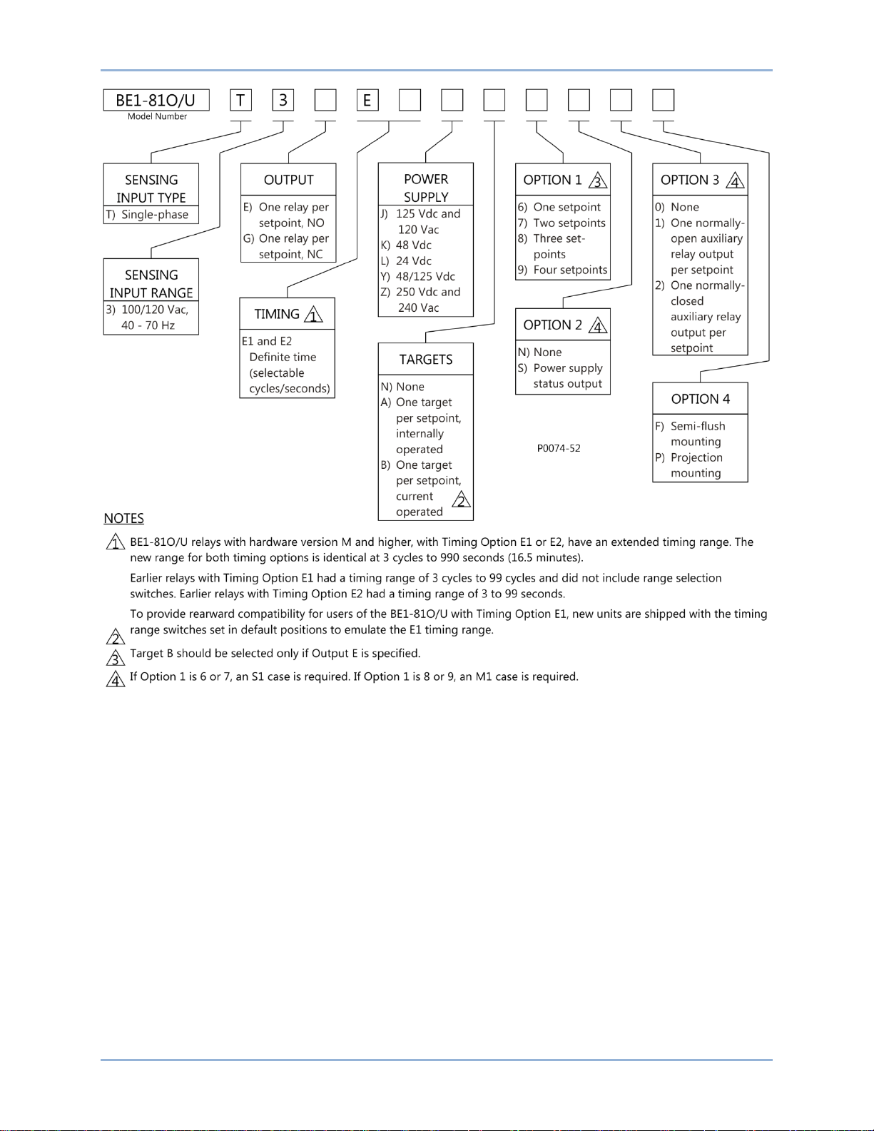
Style Number
BE1-81O/U electrical characteristics and operating features are defined by a combination of letters and
numbers that make up the relay style number. The style number describes the features and options of a
particular relay and appears on the front panel, draw-out cradle assembly, and the relay case. The style
number identification chart shown in Figure 1
illustrates the features and options for the BE1-81O/U relay.
BE1-81O/U Introduction
Page 8
2 9137300990 Rev N
Figure 1. Style Chart
Introduction BE1-81O/U
Page 9
9137300990 Rev N 3
Locator
Function
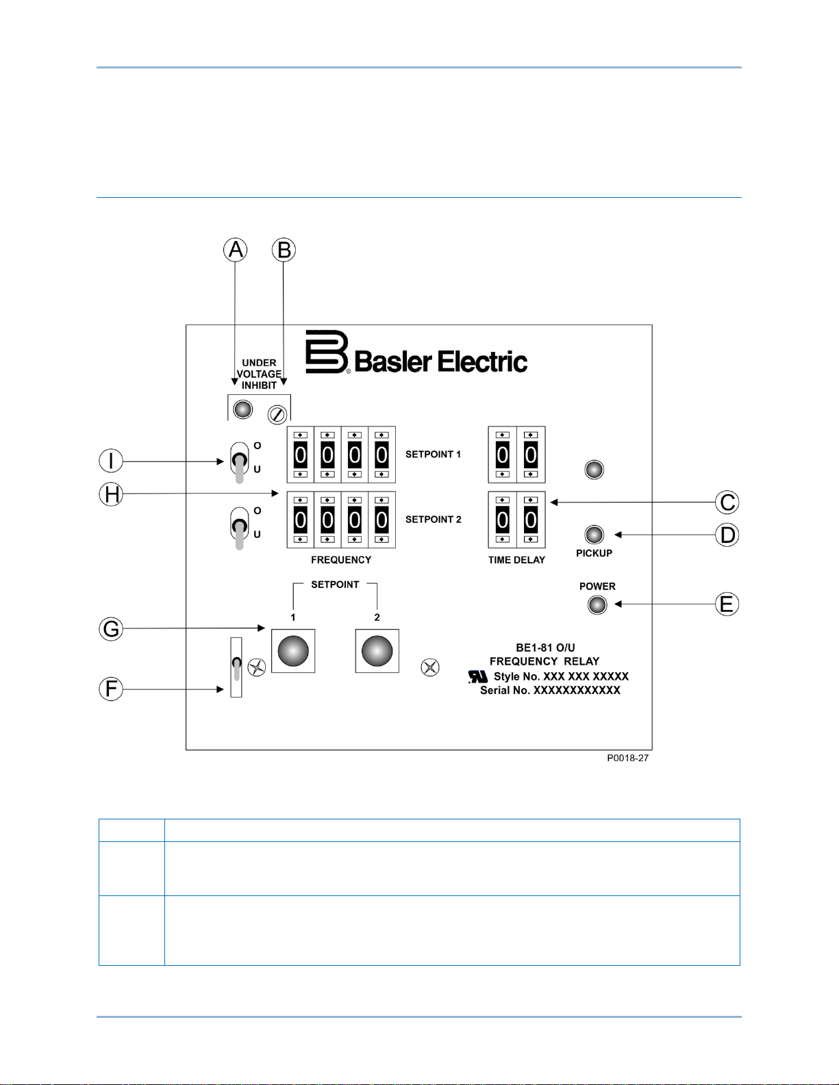
A
Undervoltage Inhibit Indicator. This light emitting diode (LED) lights when the sensed
inhibited when this LED is on.
B
Undervoltage Inhibit Control. Relay operation is inhibited when the sensed voltage
set at 80 Vac.
Controls and Indicators
BE1-81O/U controls and indicators are located on the front panel and circuit boards.
Front Panel
The front-panel control and indicators are shown in Figure 2 and described in Table 1.
Figure 2. Front-Panel Controls and Indicators
Table 1. Front-Panel Controls and Indicators
voltage decreases below the setting of the Undervoltage Inhibit Control. Relay operation is
decreases below the setting of this multi-turn potentiometer. The Undervoltage Inhibit
Control has a setting range of 40 to 120 Vac. The BE1-81O/U is delivered with the control
BE1-81O/U Controls and Indicators
Page 10

4 9137300990 Rev N
Locator
Function
C
Time Delay Selector Switches . A set of two thumbwheel switches sets the time delay
provided for each frequency setpoint of the relay.
D
Pickup Indicator. When an underfrequency or overfrequency condition is detected, the
level.
E
Power Indicator. This LED lights when operating power is applied to the relay.
F
Target Reset Switch. Operating this switch resets all of the target indicators.
G
Target Indicators. Electronically-latching red target indicators illuminate when the associated
operated targets, the trip circuit current must be greater than 200 milliamperes.
H
Frequency Selector Switches. A set of four thumbwheel switches adjusts the setpoint
protection.
I
Over/Under Selector Switch. A two-position toggle switch configures the corresponding
selector switch is provided for each frequency setpoint of the relay.
between the corresponding frequency setpoint (locator H) pickup and output re lay r eact ion.
The time delay obtained by these switches is affected by the setting of Selector Switch S7.
See Circuit Board for details about configuring S7. One set of two thumbwheel switches is
corresponding pickup indicator lights and stays lit until the frequency returns to a non-trip
setpoint output relay energizes. When the optional targets are specified, a target indicator is
provided for each frequency setpoint of the relay. To ensure proper operation of current-
frequency in 0.01 hertz increments over an allowable range of 40 to 70 hertz. One set of
four thumbwheel switches is provided for each frequency setpoint of the relay. Note that
selecting a setting outside the 40 to 70 hertz range will result in a loss of frequency
frequency setting (locator H) as an overfrequency (O) or underfrequency (U) setpoint. One
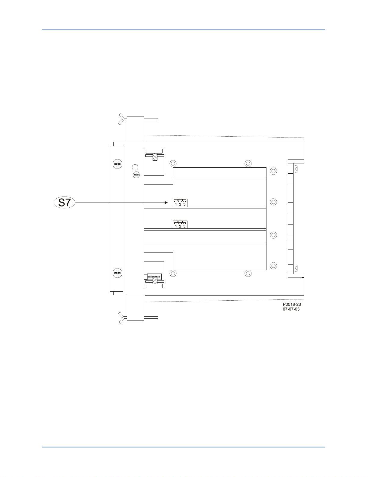
Circuit Board
A single control, Selector Switch S7, is located on the Definite Time circuit boards. (The number of
Definite Time circuit boards corresponds to the number of setpoints specified by the relay style number.)
S7 configures the Time Delay Selector Switches (Table 1, locator C) to adjust the definite time delay in
seconds or cycles and have a multiplier of times 1, 10, or 100.
With the cradle assembly withdrawn from the case, the three-section Selector Switches are accessed at
the right side of the cradle assembly. Figure 3 illustrates the location of S7 on a BE1-81O/U relay with two
setpoints.
Multiplier Settings
Sections S7-1 and S7-2 configure the multiplier used with the Time Delay Selector Switches.
For a times one (X1) multiplier, S7-1 and S7-2 ar e placed in the down position.
For a times 10 (X10) multiplier, S7-1 is placed in the up position and S7-2 is placed in the down position.
A times 10 multiplier is also obtained when S7-1 is placed in the down position and S7-2 is placed in the
up position.
For a times 100 (X100) multiplier, S7-1 and S7-2 are placed in the up position.
Cycles/Seconds Settings
S7-3 either selects cycles or seconds as the unit of measure for the definite time delay. S7-3 is placed in
the up position to select cycles. The down position of S7-3 selects seconds.
Controls and Indicators BE1-81O/U
Page 11
9137300990 Rev N 5
Figure 3. Location of Selector Switch S7
BE1-81O/U Controls and Indicators
Page 12

6 9137300990 Rev N
Controls and Indicators BE1-81O/U
Page 13

9137300990 Rev N 7
Functional Description
The BE1-81O/U has one to four frequency setpoints for protecting an ac source from underfrequency and
overfrequency conditions within the limits of 40 to 70 hertz. When the BE1-81O/U senses an
underfrequency or overfrequency condition, an output relay energizes after a selectable time delay. Relay
operation is disabled if the sensed voltage decreases below an adjustable undervoltage inhibit setting.
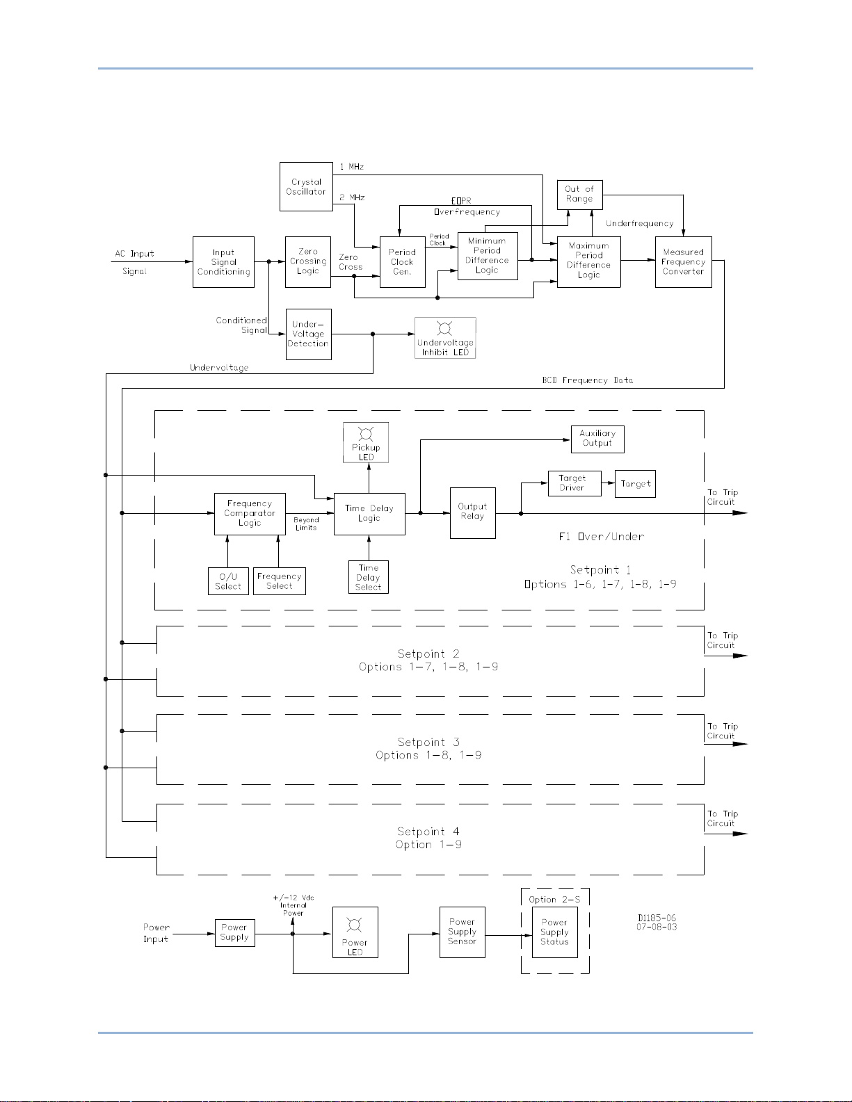
BE1-81O/U functions are illustrated in the block diagram of Figure 4 and described in the following
paragraphs.
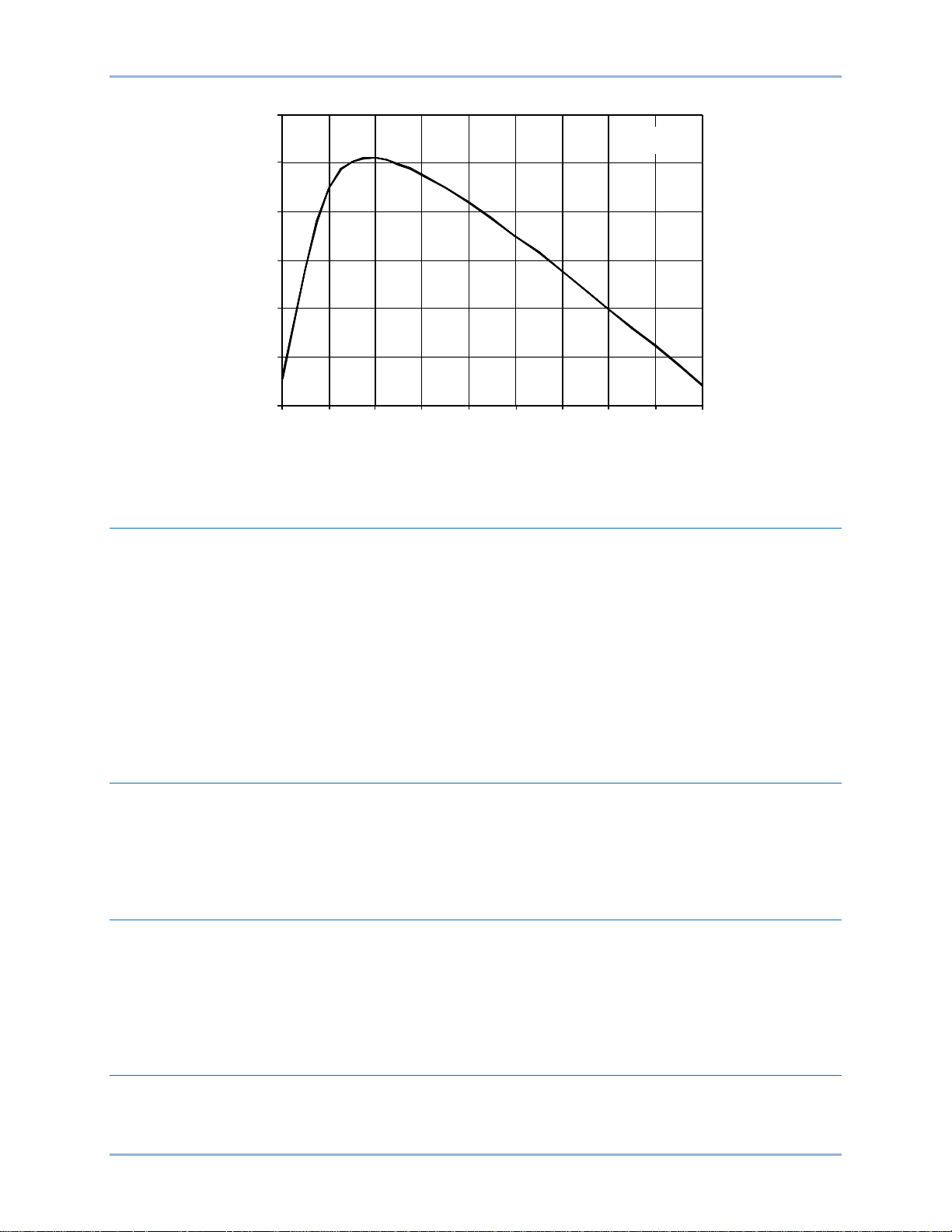
Input Signal
Because input signal crossings are used to measure the input frequency, it is necessary to filter unwanted
harmonics and transients. Some attenuation of the input signal results. Figure 5 shows the attenuation, in
decibels, for input frequencies of 12 to 200 Hz.
A single-phase voltage is applied to an input signal conditioning circuit that consists of a transformer and
band-pass filter. The sensed input signal is applied to the zero-crossing logic and undervoltage detection
circuits.
Undervoltage Inhibit
This circuit prevents the output relays from energizing during an undervoltage condition associated with
equipment startup. The circuit prevents operation of the zero-cross logic and time delay logic, and lights
the Undervoltage Inhibit Indicator when the level of the sensed voltage decreases below the setting. A
potentiometer, accessed through the front panel, is used to adjust the undervoltage inhibit level from 40 to
120 Vac. BE1-81O/U relays are delivered with an undervoltage inhibit setting of 80 Vac.
Zero-Crossing Logic
The zero-crossing logic circuit converts the sensed frequency to pulses synchronized to each positivegoing zero crossing of the waveform. The pulse frequency represents the period of the waveform and is
applied to the period clock generator, minimum period difference logic, and maximum period difference
logic circuits.
Crystal Oscillator
The crystal-controlled oscillator provides accurate 1 MHz and 2 MHz timing signals for the clock logic.
Period Clock Generator
A frequency comparison is made for each cycle of sensed frequency. The period clock generator supplies
a reference signal that is synchronized with the beginning of each cycle of the sensed frequency. At each
zero-crossing pulse, the clock gates the 2 MHz period clock pulses to the minimum period difference logic
circuit.
Minimum Period Difference Logic
Each zero-cross pulse causes this logic to count 24,580 2 MHz clock pulses, which is the period of the 80
hertz maximum detectable frequency limit. When the sensed frequency is less than the limit, an end-ofperiod reference (EOPR) pulse is generated to initiate the maximum period difference and measurement
logic.
BE1-81O/U Functional Description
Page 14
8 9137300990 Rev N
However, if the sensed frequency equals or exceeds the 80 hertz maximum frequency limit (zero-cross
pulses interrupt the counts) for three consecutive cycles, the maximum period difference logic is
bypassed. The measured-frequency converter then computes the frequency at this maximum frequency
limit. The definite time delay is not affected by the frequency limit being exceeded.
Figure 4. BE1-81O/U Functional Block Diagram
Functional Description BE1-81O/U
Page 15
9137300990 Rev N 9
Frequency (HZ)
dB
12
13
14
15
16
17
18
12 40 60 80 100 120 140 160 180 200
D2856-24
Figure 5. Band-Pass Filter Characteristics
Maximum Period Difference Logic
This logic includes an address resister and programmable, read-only memory (PROM). Following the
EOPR pulse from the minimum period difference logic, the address register counts 1 MHz clock pulses to
address 4,096 data words stored in the PROM. Completion of the count represents the period of the 30
Hz minimum detectable frequency limit. If zero-cross pulses have properly occurred before the count
ends, the measured frequency converter computes the actual frequency, within the frequency limits,
utilizing the corresponding data words stored in the PROM.
If sensed frequency decreases to less than the 30 Hz minimum frequency limit (zero-cross pulses occur
after the counts are completed) for three consecutive cycles, the measured frequency converter
computes the frequency at the minimum frequency limit. The definite time delay is not affected by the
frequency limit being exceeded.
Measured Frequency Converter
The measured frequency converter changes the data word from the maximum period difference logic to a
four-digit, binary-coded decimal (BCD) number that represents the actual sensed frequency (with an
accuracy of 0.01 Hz) within the 30 to 80 Hz limits. The BCD frequency data bus passes this data to the
frequency comparator logic of each setpoint.
Frequency Comparator Logic
This logic compares the BCD number representing the actual sensed frequency with the Frequency
Selector Switch setting on the front panel. An output is triggered when the sensed frequency decreases
below the setpoint (Over/Under Selector Switch set to U), or when the sensed frequency increases above
the setpoint (Over/Under Selector Switch set to O). The resultant output consists of an enabling level that
starts a count-up timer and lights the front panel Pickup Indicator.
Definite Time Delay Logic
The enable signal (representing a detected over or underfrequency condition) from the frequency
comparator logic initiates the count of zero-cross pulses. After three consecutive cycles exceed the
pickup setting, the definite time delay logic lights the Pickup Indicator. When the front-panel Time Delay
BE1-81O/U Functional Description
Page 16

10 9137300990 Rev N
Note
Note
Time Delay
Selector Switch
Selector Switch S7
S7-1, 2
S7-3
25
X1
Cycles
25 cycles
X10
Cycles
250 cycles
X100
Cycles
2,500 cycles
X1
Seconds
2.5 seconds
X10
Seconds
25 seconds
X100
Seconds
250 seconds
Selector Switch setting is reached, the logic energizes the setpoint output relay. The total time delay, with
seconds-type timing selected, is the Time Delay Selector Switch setting plus one cycle of the sensed
input plus 0.008 seconds (output relay delay). The Pickup LED remains lit until the frequency condition is
corrected. When the sensed frequency returns to normal for three cycles, the Pickup LED and output
relay reset.
When delay is set in cycles, the relay calculates delay using a zero-cross counter. Hence, the measured
delay will vary with incoming frequency. The time delay may be calculated as follows.
𝑑𝑒𝑙𝑎𝑦 (𝑠𝑒𝑐𝑜𝑛𝑑𝑠 =
If 00, 01, or 02 is set as the time delay, the relay response will vary according to the revision level of the
relay. The revision-dependent response of the relay may include a block of relay tripping, a trip as fast as
two cycles, or a trip in three or more cycles.
A delay setting of 00, 01, or 02 cycles should not be used unless the
relay response to the setting is tested and found acceptable.
When delay is set in seconds, the relay calculates delay using an internal clock. This gives a time delay
that will not change as the sensed frequency changes.
𝑑𝑒𝑙𝑎𝑦 𝑠𝑒𝑡𝑡𝑖𝑛𝑔 𝑖𝑛 𝑐𝑦𝑐𝑙𝑒𝑠
𝑎𝑝𝑝𝑙𝑖𝑒𝑑 𝑓𝑟𝑒𝑞𝑢𝑒𝑛𝑐𝑦 𝑖𝑛 ℎ𝑒𝑟𝑡𝑧
×(± 𝑠𝑝𝑒𝑐𝑖𝑓𝑖𝑐𝑎𝑡𝑖𝑜𝑛 𝑎𝑐𝑐𝑢𝑟𝑎𝑐𝑦
)
Time Delay Selection
Time delay selection is controlled by Selector Switch S7 on the definite time circuit board. S7 is a usersettable, three-section switch for selecting definite timing in seconds or cycles and a multiplier of times 1,
10, or 100.
Earlier BE1-81O/U relays with timing option E1 had a timing range of 3
to 99 cycles and did not include Selector Switch S7. Earlier relays with
timing option E2 had a timing range of 3 to 99 cycles.
To provide rearward compatibility for users of earlier BE1-81O/U
relays with timing option E1, relays are delivered with S7 set to
emulate the E1 timing range.
Sections S7-1 and S7-2 configure the multiplier used with the Time Delay Selector Switches. For a times
one (X1) multiplier, S7-1 and S7-2 are placed in the down position. For a times 10 (X10) multiplier, S7-1 is
placed in the up position and S7-2 is placed in the down position. A times 10 multiplier is also obtained
when S7-1 is placed in the down position and S7-2 is placed in the up position. For a times 100 (X100)
multiplier, S7-1 and S7-2 are placed in the up position.
Section S7-3 either selects cycles or seconds as the unit of measure for the definite time delay. S7-3 is
placed in the up position to select cycles. The down position of S7-3 selects seconds.
Table 2 lists some time delay setting examples.
Table 2. Time Delay Setting Examples
Functional Description BE1-81O/U
Time Delay
Page 17

9137300990 Rev N 11
Relay Outputs
The time delay logic output for each setpoint energizes an associated output relay that is normally open
(output type E) or normally closed (output type G). The relay output type specified is the same for each
setpoint included in the relay.
Auxiliary Relay Outputs
An auxiliary relay may be specified that is energized simultaneously with the output relay. The relay
contacts are either normally open (option 3-1) or normally closed (option 3-2). When specified, this option
is included for each setpoint and is the same contact type for all setpoints within a relay.
Power Supply
BE1-81O/U internal circuitry is powered by one of three wide-range power supplies. Power supply voltage
ratings are listed in the Specifications chapter.
Relay operating power is developed by the wide-range, isolated, low-burden, flyback-switching power
supply. Input power (source voltage) for the power supply is not polarity sensitive. The front-panel Power
Indicator lights to indicate that the power supply is functioning properly.
Power Supply Status Output
The optional power supply status output relay (option 2-S) has a set of normally closed contacts that are
energized open during normal operation. If the power supply output fails (or operating power is removed
from the relay), the power supply status output relay de-energizes and the contacts close.
Target Indicators
Target indicators are optional components selected when a relay is ordered. The electronically-latched
and reset targets consist of red LED indicators located on the relay front panel. A latched target is reset
by operating the target reset switch on the front panel. If relay operating power is lost, any illuminated
(latched) targets are extinguished. When relay operating power is restored, the previously latched targets
are restored to their latched state.
A relay can be equipped with either internally operated targets or current operated targets.
Internally Operated Targets
The relay trip outputs are directly applied to drive the appropriate target indicator. Each indicator is
illuminated regardless of the current level in the trip circuit.
Current Operated Targets
A current operated target is triggered by closure of the corresponding output contact and the presence of
at least 200 milliamperes of current flowing in the trip circuit.
BE1-81O/U Functional Description
Page 18

12 9137300990 Rev N
Functional Description BE1-81O/U
Page 19

9137300990 Rev N 13
Note
Installation
BE1-81O/U relays are shipped in sturdy cartons to prevent damage during transit. Upon receipt of a relay,
check the model and style number against the requisition and packing list to confirm that they agree.
Inspect the relay for shipping damage. If there is evidence of damage, file a claim with the carrier and
notify Basler Electric.
If the relay will not be installed immediately, place the relay in its original shippin g c arton and stor e in a
moisture- and dust-free environment.
Operating Precautions
Before installing the relay, note the following precautions.
• A minimum of 200 milliamperes in the output contact circuit is required to ensure reliable
operation of current operated targets.
• When the connection plugs are removed, the relay is disconnected from the operating circuit and
will not provide system protection. Always be sure that external operating conditions are stable
before removing a relay from service. Also, ensure that connection plugs are installed before
replacing the case cover.
Be sure that the relay is hard-wired to earth ground with no smaller
than 12 AWG copper wire attached to the ground terminal on the rear
of the relay case. When the relay is configured in a system with other
devices, it is recommended to use a separate lead to the ground bus
from each device.
Mounting
Because the relay is of solid-state design, it does not have to be mounted vertically. Any convenient
mounting angle may be chosen. Relay outline dimensions and panel drilling diagrams are illustrated in
Figures 6 through 24.
BE1-81O/U Installation
Page 20

14 9137300990 Rev N
3.03 (77)
6.06 (154)
0.25 (6) diameter, 4 places
C
L
Cut-Out
0.575
(15)
8.63
(219)
0.552
(14)
5.69 (144)
Outer Edge of Cover
0.480
(12)
8.25
(210)
4.13
(105)
0.480
(12)
P0072-12
Figure 6. Panel Cutting/Drilling, Semi-Flush, S1 Case
Installation BE1-81O/U
Page 21

9137300990 Rev N 15
Figure 7. S1 Case Dimensions, Rear View, Double Ended, Semi-Flush Mount
BE1-81O/U Installation
Page 22

16 9137300990 Rev N
.75
(19.1)
(157.2)
6.19
(49.53)
1.95
10-32 SCREWS
(7.9)
.31
10-32 SCREWS
(102.4)
4.03
4.03
(102.4)
(7.9)
.31
MOUNTING PANEL
(55.75)
2.195
P0066-64
Figure 8. S1 Case Dimensions, Side View, Double Ended, Semi-Flush Mount
Installation BE1-81O/U
Page 23

9137300990 Rev N 17
Figure 9. S1 Case Dimensions, Rear View, Single Ended, Semi-Flush Mount
BE1-81O/U Installation
Page 24

18 9137300990 Rev N
.75
(19.1)
(157.2)
6.19
(49.53)
1.95
10-32 SCREWS
MOUNTING PANEL
(55.75)
2.195
P0066-69
8.06
(204.72)
(7.9)
.31
Figure 10. S1 Case Dimensions, Side View, Single Ended, Semi-Flush Mount
Installation BE1-81O/U
Page 25

9137300990 Rev N 19
Figure 11. Panel Cutting/Drilling, Double Ended, Projection Mount, S1 Case
BE1-81O/U Installation
Page 26

20 9137300990 Rev N
Figure 12. S1 Case Dimensions, Rear View, Double Ended, Projection Mount
Installation BE1-81O/U
Page 27

9137300990 Rev N 21
.75
(19.1)
(157.2)
6.19
(49.53)
1.95
10-32 SCREWS
(7.9)
.31
10-32 SCREWS
(102.4)
4.03
4.03
(102.4)
(7.9)
.31
(55.75)
2.195
P0066-67
TERMINAL EXTENSION (TYP.)
FOR DETAILED INSTRUCTIONS,
SEE THE TERMINAL PROJECTION
MOUNTING KIT SUPPLIED.
.25
(6.4)
5/16-18 STUD
2 PLACES
MOUNTING PANEL
Figure 13. S1 Case Dimensions, Side View, Double Ended, Projection Mount
BE1-81O/U Installation
Page 28

22 9137300990 Rev N
Figure 14. Panel Cutting/Drilling, Single Ended, Projection Mount, S1 Case
Installation BE1-81O/U
Page 29

9137300990 Rev N 23
Figure 15. S1 Case Dimensions, Rear View, Single Ended, Projection Mount
BE1-81O/U Installation
Page 30

24 9137300990 Rev N
(157.2)
6.19
(49.53)
1.95
10-32 SCREWS
MOUNTING PANEL
(55.75)
2.195
P0066-71
TERMINAL EXTENSION (TYP.)
FOR DETAILED INSTRUCTIONS,
SEE THE TERMINAL PROJECTION
MOUNTING KIT SUPPLIED.
.25
(6.4)
5/16-18 STUD
2 PLACES
MOUNTING PANEL
8.06
(204.72)
(7.9)
.31
.75
(19.1)
Figure 16. S1 Case Dimensions, Side View, Single Ended, Projection Mount
Installation BE1-81O/U
Page 31

9137300990 Rev N 25
P0066-68
Figure 17. S1 Case Cover Dimensions, Front View
BE1-81O/U Installation
Page 32

26 9137300990 Rev N
3.03 (77)
6.06 (154)
0.25 (6) diameter, 4 places
C
L
Cut-Out
0.575
(15)
14.63
(371.5)
0.552
(14)
5.69 (144.5)
Outer Edge of Cover
0.480
(12)
14.25
(362.1)
7.13
(181.0)
0.480
(12)
P0072-21
7.31
(185.7)
2.84 (72.1)
Figure 18. Panel Cutting/Drilling, Semi-Flush, M1 Case
Installation BE1-81O/U
Page 33

9137300990 Rev N 27
Figure 19. M1 Case Dimensions, Rear View, Double Ended, Semi-Flush Mount
BE1-81O/U Installation
Page 34

28 9137300990 Rev N
P0066-76
10-32 SCREWS
10-32 SCREWS
MOUNTING PANEL
2.195
(55.75)
.31
(7.9)
.31
(7.9)
.75
(19.1)
6.19
(157.2)
1.95
(49.53)
7.03
(178.56)
7.03
(178.56)
Figure 20. M1 Case Dimensions, Side View, Double Ended, Semi-Flush Mount
Installation BE1-81O/U
Page 35

9137300990 Rev N 29
Figure 21. Panel Cutting/Drilling, Double Ended, Projection Mount Case
BE1-81O/U Installation
Page 36

30 9137300990 Rev N
Figure 22. M1 Case Dimensions, Rear View, Double Ended, Projection Mount
Installation BE1-81O/U
Page 37

9137300990 Rev N 31
P0066-78
10-32 SCREWS
10-32 SCREWS
2.195
(55.75)
.31
(7.9)
.31
(7.9)
.75
(19.1)
6.19
(157.2)
1.95
(49.53)
7.03
(178.56)
7.03
(178.56)
TERMINAL EXTENTION (TYP.)
FOR DETAILED INSTRUCTIONS,
SEE THE TERMINAL PROJECTION
MOUNTING KIT SUPPLIED.
.25
(6.4)
5/16-18 STUD
2 PLACES
MOUNTING PANEL
Figure 23. M1 Case Dimensions, Side View, Double Ended, Projection Mount
BE1-81O/U Installation
Page 38

32 9137300990 Rev N
P0066-79
Figure 24. M1 Case Cover Dimensions, Front View
Installation BE1-81O/U
Page 39

9137300990 Rev N 33
Connections
Relay circuitry connects to the case terminals through removable connection plugs (one plug for 10terminal cases and two plugs for 20-terminal cases). Removal of the connection plugs opens the
normally-open trip contact circuits and short-circuits the normally-closed trip contact circuits before
opening the power and sensing circuits.
Incorrect wiring may result in damage to the relay. Except for the ground wire, connections should be
made with wire no smaller than 14 AWG. Typical internal connections are shown in Figure 25. External
connections are shown in Figures 26 and 27.
BE1-81O/U Installation
Page 40

34 9137300990 Rev N
Figure 25. Internal Relay Connections
Installation BE1-81O/U
Page 41

9137300990 Rev N 35
Maintenance
Figure 26. Typical DC Connections
Figure 27. Typical AC Sensing Connections
BE1-81O/U relays require no preventative maintenance other than a periodic operational check. If the
relay fails to function properly, contact Technical Sales Support at Basler Electric to coordinate repairs.
Storage
This device contains long-life aluminum electrolytic capacitors. For devices that are not in service (spares
in storage), the life of these capacitors can be maximized by energizing the device for 30 minutes once
per year.
BE1-81O/U Installation
Page 42

36 9137300990 Rev N
Installation BE1-81O/U
Page 43

9137300990 Rev N 37
Note
Testing
Procedures in this section are used for testing and adjusting a BE1-81O/U relay for the desired operation
in a protective scheme.
Test Equipment
Minimum test equipment requirements are listed below. Test connections are shown in Figure 28.
One of the commercially available frequency relay test set may be
used to test the relay. These test sets have electronic switching and
frequency and time generating accuracies that exceed the accuracy of
the BE1-81O/U relay.
• Ac or Dc power source for relay operating power
• Ac source for relay frequency sensing*
• Hardware (battery and lamp, multimeter, etc.) or method of determining when the relay output
contacts close
* A source with frequency stability of 0.00002 hertz must exhibit phase noise of less than 90 decibels for
accurate measurement. The accuracy and stability of this source is necessary as the relay precisely
measures the period between positive-going zero crossings of the applied waveform and responds
instantaneously to the sensed condition.
Operational Test
Operational testing is divided into testing of frequency pickup settings, selector settings, time delays, and
the undervoltage inhibit function.
High and Low Frequency Pickup
1. Connect the relay as shown in Figure 28.
2. Adjust selector switch S7 for setpoint 1, located on the definite time circuit board controlling setpoint
1, to obtain a time delay in cycles with a x1 multiplier (S7-1 down, S7-2 down, and S7-3 up).
3. Adjust the front panel, Setpoint 1 controls to the following settings:
• Over/Under Selector Switch: Over (O) position
• Frequency Selector Switch: 70.00
• Time Delay Selector Switch: 25
4. Apply operating power to the relay.
5. Apply 60-hertz voltage to the relay sensing input. The level of voltage must exceed the setting of the
adjustable, front-panel Undervoltage Inhibit control.
6. Slowly increase the sensing input frequency until the Setpoint 1 Pickup indicator just lights. The
sensing input frequency should be 70 Hz, ±0.01 Hz.
7. Adjust the front panel, Setpoint 1 controls to the following settings:
• Over/Under Selector Switch: Under (U) position
• Frequency Selector Switch: 50.00
8. Slowly decrease the sensing input frequency until the Setpoint 1 Pickup indicator just lights. The
sensing input frequency should be 50 Hz, ±0 .01 Hz .
BE1-81O/U Testing
Page 44

38 9137300990 Rev N
Figure 28. BE1-81O/U Test Setup
Frequency Selector Settings
1. Connect the relay as shown in Figure 28.
2. Adjust the front panel, Setpoint 1 controls to the following settings:
• Over/Under Selector Switch: Under (U) position
• Frequency Selector Switch: 51.11
3. Apply operating power to the relay.
4. Apply 60-hertz voltage to the relay sensing input. The level of voltage must exceed the setting of the
adjustable, front-panel Undervoltage Inhibit control.
Testing BE1-81O/U
Page 45

9137300990 Rev N 39
5. Slowly decrease the sensing input frequency until the Setpoint 1 Pickup indicator just lights. The
sensing input frequency should be 51.11 Hz, ±0.01 Hz.
6. Repeat steps 4 and 5 for Frequency Selector Switch settings of 52.22, 54.44, and 58.88.
Definite Time Delay – Cycles
1. Connect the relay as shown in Figure 28.
2. Adjust Selector Switch S7 for setpoint 1, located on the definite time circuit board controlling setpoint
1, to obtain a time delay in cycles with a x1 multiplier (S7-1 down, S7-2 down, and S7-3 up).
3. Adjust the front panel, Setpoint 1 controls to the following settings:
• Over/Under Selector Switch: Under (U) position
• Frequency Selector Switch: 55.00
• Time Delay Selector Switch: 11
4. Apply operating power to the relay.
5. Apply 60-hertz voltage to the relay sensing input. The level of voltage must exceed the setting of the
adjustable, front-panel Undervoltage Inhibit control.
6. Ensure that the target indicators are reset.
7. Step the sensing input frequency down from 60 Hz to 53 Hz. The Setpoint 1 Pickup indicator lights
and the test set timer begins counting. When the time delay ends, the setpoint 1 output relay and
target trips, and the test set timer stops counting. The timer should indicate 0.208 seconds (11 cycles
x 1/53, ±1.0 cycles).
8. Restore the sensing input frequency to 60 Hz and reset the targets.
9. Repeat steps 7 and 8 for Time Delay Selector Switch settings of 22, 44, and 88.
10. If desired, the above steps may be performed with Selector Switch S7 configured for a time delay
multiplier of x10 (S7-1 up and S7-2 down) or x100 (S7-1 up and S7-2 up).
Definite Time Delay – Seconds
1. Connect the relay as shown in Figure 28.
2. Adjust Selector Switch S7 for setpoint 1, located on the definite time circuit board controlling setpoint
1, to obtain a time delay in seconds with a x1 multiplier (S7-1 down, S7-2 down, and S7-3 down).
3. Adjust the front panel, Setpoint 1 controls to the following settings:
• Over/Under Selector Switch: Under (U) position
• Frequency Selector Switch: 55.00
• Time Delay Selector Switch: 25
4. Apply operating power to the relay.
5. Apply 60-hertz voltage to the relay sensing input. The level of voltage must exceed the setting of the
adjustable, front-panel Undervoltage Inhibit control.
6. Ensure that the target indicators are reset.
7. Step the sensing input frequency down from 60 Hz to 53 Hz. The Setpoint 1 Pickup indicator lights
and the test set timer begins counting. When the time delay ends, the setpoint 1 output relay and
target trips, and the test set timer stops counting. The timer should indicate 2.5 seconds, ±0.05
seconds.
8. Restore the sensing input frequency to 60 Hz and reset the targets.
9. Repeat steps 7 and 8 for Time Delay Selector Switch settings of 22, 44, and 88.
10. If desired, the above steps may be performed with Selector Switch S7 configured for a time delay
multiplier of x10 (S7-1 up and S7-2 down) or x100 (S7-1 up and S7-2 up).
BE1-81O/U Testing
Page 46

40 9137300990 Rev N
Undervoltage Inhibit
1. Connect the relay as shown in Figure 28.
2. Adjust the front panel, Setpoint 1 controls to the following settings:
• Over/Under Selector Switch: Under (U) position
• Frequency Selector Switch: 60.00
• Time Delay Selector Switch: 25
3. Apply operating power to the relay.
4. Apply 60-hertz voltage to the relay sensing input. The level of voltage must exceed the setting of the
adjustable, front-panel Undervoltage Inhibit control.
5. Decrease the level of the sensing input voltage until it is considerably less than the Undervoltage
Inhibit control setting. (BE1-81O/U relays are delivered with an undervoltage inhibit setting of 80 Vac.)
The Undervoltage Inhibit indicator should light.
6. Decrease the frequency of the sensing input voltage to 59 Hz. The Setpoint 1 Pickup indicator should
not light and the setpoint 1 output relay should not trip.
7. Increase the level of the sensing input voltage until it exceeds the level of the undervoltage inhibit
setting. The Undervoltage Inhibit indicator should turn off, the Setpoint 1 Pickup indicator should light,
and the setpoint 1 output relay should trip after the Time Delay Selector switch setting expires.
Setpoint 2, 3, and 4 Testing
Where applicable, the preceding tests can be performed for setpoints 2, 3, and 4 by reconnecting the
output connections for each setpoint and substituting the appropriate setpoint numbers in the test steps.
Testing BE1-81O/U
Page 47

9137300990 Rev N 41
Input Voltage
Nominal
Range
K (mid-range)
48 Vdc
24 to 150 Vdc
3.6 W
J (mid-range)
125 Vdc
120 Vac
24 to 150 Vdc
90 to 132 Vac
3.9 W
16.0 VA
L (low range)
24 Vdc
12 to 32 Vdc*
3.7 W
Y (mid-range)
48 Vdc
125 Vdc
24 to 150 Vdc
24 to 150 Vdc
3.6 W
3.9 W
Z (high range)
250 Vdc
240 Vac
68 to 280 Vdc
90 to 270 Vac
3.9 W
24.6 VA
Specifications
BE1-81O/U relays have the following features and capabilities.
Sensing Input
Voltage Range ..................................................... 40 to 132 Vac
Frequency
Detection Range .................................................. 30 to 80 Hz (Revision D and subsequent)
35 to 80 Hz (Revision C and previous)
Computation Range ............................................. 40 to 70 Hz
Burden .................................................................. 2 VA maximum
Operating Power Input
Relay operating power may be obtained from a wide variety of external voltage sources. When ordering,
any one of five internal power supply types may be selected to match the operating power voltage level
available at your site. Available power supply types are listed in Table 3.
Table 3. Power Supply Types
Type
* The type L power supply initially requires 14 Vdc to begin operating. Once operating, the voltage may
be reduced to 12 Vdc and operation will continue.
Burden at Nominal
Relay Outputs
One relay output is provided for each setpoint. Relay outputs can be specified as normally open or
normally closed. One normally open or normally closed auxiliary relay output per setpoint is also available
as an option.
Output Contacts
Resistive Ratings
120 Vac ............ Make, break, and carry 7 Aac continuously
250 Vdc ............ Make and carry 30 Adc for 0.2 seconds, carry 7 Adc continuously, and break 0.3 Adc
500 Vdc ............ Make and carry 15 Adc for 0.2 seconds, carry 7 Adc continuously, and break 0.3 Adc
Inductive Ratings
120 Vac, 125 Vdc, 250 Vdc........ Break 0.3 A (L/R = 0.04)
Target Indicators (Optional)
Electronically-latching, manually-reset targets indicate that a setpoint contact has energized. Either
internally-operated or current-operated targets may be specified.
BE1-81O/U Specifications
Page 48

42 9137300990 Rev N
Current-operated targets require a minimum trip-circuit current of 200 millia mperes and have a continuous
rating of 3 amperes, a two-minute rating of 7 amperes, and a one-second rating of 30 amperes.
Internally-operated targets should be selected if the relay has normally-closed output contacts.
Frequency Setpoint
Range ................................................................... 40 to 70 Hz
Increment ............................................................. 0.01 Hz
Accuracy............................................................... ±0.01 Hz of the setpoint setting
Time Delay
Setting Range
Cycles (of applied frequency)............................... 3 to 99 cycles in 1 cycle increments
10 to 990 cycles in 10 cycle increments
100 to 9,900 cycles in 100 cycle increments
Seconds ............................................................... 0.1 to 9.9 seconds in 0.1 second increments
1.0 to 99 seconds in 1 second increments
10 to 990 seconds in 10 second increments
Accuracy
Cycles ................................................................... +2 cycles or –1 cycle for 0.02 Hz to 1 Hz frequency
variation from setpoint setting
±1 cycle for frequency variation greater than 1 Hz from
setpoint setting
Seconds ............................................................... ±2% of the setting or ±50 ms, whichever is greater for
0.02 Hz to 1 Hz frequency variation from setpoint
setting
±2% of the setting or ±25 ms, whichever is greater for
frequency variation greater than 1 Hz from
setpoint setting
Undervoltage Inhibit
Setting Range ...................................................... 40 to 120 Vac
Accuracy............................................................... ±5% of the setting at 25°C for nominal frequency input
Type Tests
Dielectric Strength
Meets IEC 60255-5 and exceeds IEEE C37.90 one-minute dielectric tests as follows:
All circuits to ground ............................................. 2,828 Vdc
Input to output circuits .......................................... 2,000 Vac or 2,828 Vdc
Surge Withstand Capability
Qualified to IEEE C37.90.1-1989
Fast Transient
Qualified to IEEE C37.90.1-1989
Impulse
Qualified to IEC 60255-5
Radio Frequency Interference
Maintains proper operation when tested in accordance with IE EE C37. 90-1989.
Specifications BE1-81O/U
Page 49

9137300990 Rev N 43
Field tested using a 5-watt, hand-held transceiver operating at random frequencies centered around 144
MHz and 440 MHz, with the antenna located 6 inches (152 millimeters) from the relay in both horizontal
and vertical planes.
Shock
Withstands 15 G in each of three mutually perpendicular axes.
Vibration
Withstands 2 G in each of three mutually perpendicular axes swept over the range of 10 to 500 Hz for a
total of six sweeps, 15 minutes each sweep.
Temperature Ratings
Operating.............................................................. –40°C to 70°C (–40°F to 158°F)
Storage ................................................................. –65°C to 100°C (–85°F to 212°F)
UL Recognized
UL recognized per Standard 508, UL File No. E97033. Note: Output contacts are not UL recognized for
voltages greater than 250 volts and input power supply voltages greater than 150 volts.
GOST-R
GOST-R certified per the relevant standards of Gosstandart of Russia.
Case Size
One or Two Setpoints .......................................... S1*
Three or Four Setpoints ....................................... M1*
* See the Installation chapter for case dimensions.
Weight
S1 Case................................................................ 13 lb (5.90 kg)
M1 Case ............................................................... 18 lb (8.16 kg)
BE1-81O/U Specifications
Page 50

44 9137300990 Rev N
Specifications BE1-81O/U
Page 51

9137300990 Rev N 45
Manual
E, Mar-93
• Various relay changes were incorporated into the manual
F, Apr-98
• Revised paragraph styles
G, Jun-99
• Revised style chart to reflect changes to the E1 and E2 timing
H, Sep-03
• Removed references to timing option D1
I
• This revision letter not used
J, Oct-07
• Added manual part number and revision to all footers
K, Sep-10
• Updated time delay accuracy in Section 1
L, Sep-11
• Added Figures 4-3, 4-6, 4-7, 4-10, and 4-11 for S1 single-ended
M, Feb-13
• Updated case and cover drawings in Section 4
N, Jun-14
• Corrected truncated boxes in Figure 1, Style Char t
Revision History
Table 4 provides a historical summary of the changes made to this instruction manual. Revisions are
listed in chronological order.
Table 4. Instruction Manual Revision History
Revision and Date
Change
• Section 1: Changed frequency sensing limits to 30 and 80 Hz and
deleted paragraphs concerning revision levels. Modified power
supply ranges. Changed pickup accuracy from ±0.008 Hz to ±0.01
Hz. New statement was added to Isolation, added IEEE
qualification statement, added UL recognition, corrected M1 case
weight, and corrected Inverse Time Over/Underfrequency
Characteristic Curve diagrams (Figures 1-2 and 1-3).
• Section 3: Added wide-range power supply data and deleted
Figure 3-5.
• Section 4: Extracted testing and adjustment information and
created new Section 5, Test and Adjustments. Incremented
remaining section numbers as required. Inserted additional
installation diagrams to cover all relay styles.
options
• Changed dielectric test spec ificat ion list ed in Secti ons 1 and 4
• Figures 2-3 and 3-3 were updated to show the three-position
Selector Switch S7
• All case drawings were updated to show revised case covers
• Definite time delay options test procedures (Section 5) were
modified to accommodate the new E1 and E2 timing options
• Updated power supply burden data in Secti on 1
• Updated output contact ratings in Section 1
• Updated front-panel drawings to show LED targets
• Updated target description in Section 3
BE1-81O/U Revision History
• Updated GOST-R statement in Section 1
• Updated rear case drawings in Section 4
• Updated Storage stat em ent in Section 4
case
• Removed Figure 4-9 for M1 single-ended case
Page 52

46 9137300990 Rev N
Revision History BE1-81O/U
Page 53

Page 54

12570 State R oute 143
Highland IL 62249-1074 USA
Tel: +1 618.654.23 4 1
Fax: +1 618.654.2351
email: info@basler.com
P.A.E. Les Pins
67319 Wasselonne Cedex
FRANCE
Tel: +33 3.88.87.1010
Fax: +33 3.88. 87.0808
email: franceinfo@basler.com
No. 59 Heshun Road Loufen g D istrict (N )
Suzhou Indus trial Park
215122 Suzhou
P.R. CHINA
Tel: +86 512.8227.2888
Fax: +86 512.8227.2887
email: chinainfo@basler.com
111 North Bridge Road
15-06 Peninsul a Plaz a
Singapore 1 79098
Tel: +65 68.4 4.6445
Fax: +65 68.44.8902
email: singaporeinfo@basler.com
 Loading...