

Page 1
INSTRUCTION MANUAL
FOR
RECLOSING RELAY
BE1-79A
Publication: 9310200990
Revision: J 12/11
Page 2

Page 3

INTRODUCTION
This instruction manual provides information about the operation and installation of the BE1-79A
Reclosing Relay. To accomplish this, the following information is provided:
General Information and Specifications
Controls and Indicators
Functional Description
Installation
Maintenance
WARNING!
To avoid personal injury or equipment damage, only qualified personnel should
perform the procedures in this manual.
9310200990 Rev J BE1-79A Introduction i
Page 4

First Printing: July 1997
Printed in USA
Copyright© 1997-2011 Basler Electric, Highland Illinois 62249 USA
All Rights Reserved
December 2011
CONFIDENTIAL INFORMATION
of Basler Electric, Highland Illinois, USA. It is loaned for confidential use,
subject to return on request, and with the mutual understanding that it will not
be used in any manner detrimental to the interest of Basler Electric.
It is not the intention of this manual to cover all details and variations in equipment, nor does this manual
provide data for every possible contingency regarding installation or operation. The availability and design
of all features and options are subject to modification without notice. Should further information be
required, contact Basler Electric.
BASLER ELECTRIC
12570 STATE ROUTE 143
HIGHLAND IL 62249 USA
http://www.basler.com, info@basler.com
PHONE +1 618.654.2341 FAX +1 618.654.2351
ii BE1-79A Introduction 9310200990 Rev J
Page 5

REVISION HISTORY
The following information provides a historical summary of the changes made to the BE1-79A hardware,
firmware, and software. The corresponding revisions made to this instruction manual (9310200990) are
also summarized. Revisions are listed in reverse chronological order.
Application Firmware
Version and Date Change
1.07, 02/08
1.05, 08/00
1.03.XX, 08/98
1.02.XX, 06/98
1.02.XX, 12/97
1.01.XX, 07/97
Hardware
Version and Date Change
M, 03/10
L, 02/08
K, 01/06
J, 09/04
H, 02/04
G, 05/03
F, 10/02
E, 09/00
D, 01/00
C, 10/98
B, 12/97
A, 07/97
Modified firmware so the relay will go to Lockout after the EXIT
command is entered through the RS-232 port or access has timed
out. If the breaker is closed, the relay will go to Reset after the
Lockout Timer expires.
SP-79ARS command mode parameters were changed from C
(closed) and O (open) to E (energized) and D (de-energized).
Coordinated open and close timing of outputs C5 and C6 to preserve
consistent operation of the anti-pump function.
Communication was made consistent with other Basler products by
adding line feeds to ASCII data returned by the relay.
Initial release of part number 9310200200.
Initial release of part numbers 9310200100 and 9310200101.
Production change to digital board.
Released firmware version 1.07
Improved digital board to prevent misoperation at high voltage and
high temperature.
Changed resistors used in power supply holdup module to improve
performance in surge applications.
Changed obsolete resonator on digital board.
Initial release of part number 9310200201.
Made changes to engineering documentation.
Added RS Contact Switch S5 for user-selection of normally-open or
normally-closed RS contacts.
Contact sensing jumpers added to the digital circuit board of relays
with part number 9310200101 gave inputs V1, V2, V3, and V4 three
specific ranges of operating voltage.
Changed serialization format to HXXXXXXXX.
Initial release of part number 9310200200.
Initial release of part numbers 9310200100 and 9310200101.
Manual
Revision and Date
J, 12/11
9310200990 Rev J BE1-79A Introduction iii
In Table 1-1, stated that connection plugs are included with all relays.
In Figures 3-2 and 3-3, added shorting bars between terminals 15 &
16 and removed shorting bars between terminals 1 & 2.
Change
Page 6

Manual
Revision and Date Change
H, 07/10
Expanded Table 1-1, BE1-79A Versions and Features.
Revised rating for output contacts under Specifications in Section 1.
Added GOST-R statement in Section 1.
G, 02/08
Added manual part number and revision to footers.
Updated Output Contact ratings in Section 1.
Updated Lockout description in Section 3 to support version 1.07
firmware.
Updated Command Descriptions in Section 4 to support version 1.07
firmware.
F, 10/05
Added switch S4 labels to Figure 2-3.
In Figures 3-1, 6-1, and 6-2, enhanced C8 function block illustration to
show NO or NC contact selectable by switch S5. Changed C10 from
NC to NO.
Added RS Mode Selector switch illustration and corrected shorting
bars placement in Figures 3-2 and 3-3.
Changed name of Section 4 from Communication to Communication
Commands.
Changed name of Section 5 from Installation to Installation and
Configuration.
Corrected and clarified connection drawings of Figures 5-4 and 5-5.
Added troubleshooting tips to Section 6.
Moved contents of Section 7 to Section 1 and deleted Section 7.
Added Appendix A, RS Contact Application.
Added Appendix B, Terminal Communication.
E, 04/03
Added information pertaining to part number 9310200201.
Clarified the weight specification in Section 1.
Corrected error in Figure 5-4.
D, 08/00
Covered addition of RS Contact Switch S5 and changes to SP-
79ARS command.
C, 01/00
Information pertaining to the jumper-selectable contact sensing
voltage ranges was added. Drawings in Figure 5-1 were changed to
show the revised relay case cover.
B, 05/98
Patent information was added to Section 1. Various errors in Sections
1, 3, and 6 were corrected.
A, 09/97
―, 07/97
Information pertaining to the power supply holdup feature was added.
Initial release
iv BE1-79A Introduction 9310200990 Rev J
Page 7

CONTENTS
SECTION 1 • GENERAL INFORMATION ................................................................................................ 1-1
SECTION 2 • CONTROLS AND INDICATORS ........................................................................................ 2-1
SECTION 3 • FUNCTIONAL DESCRIPTION ........................................................................................... 3-1
SECTION 4 • COMMUNICATION COMMANDS ...................................................................................... 4-1
SECTION 5 • INSTALLATION AND CONFIGURATION .......................................................................... 5-1
SECTION 6 • TESTING ............................................................................................................................ 6-1
APPENDIX A • RS CONTACT APPLICATION ......................................................................................... A-1
APPENDIX B • TERMINAL COMMUNICATION ....................................................................................... B-1
9310200990 Rev J BE1-79A Introduction v
Page 8

vi BE1-79A Introduction 9310200990 Rev J
Page 9

SECTION 1 • GENERAL INFORMATION
TABLE OF CONTENTS
SECTION 1 • GENERAL INFORMATION ................................................................................................ 1-1
Description ............................................................................................................................................. 1-1
Features ................................................................................................................................................. 1-2
Controls and Indicators ...................................................................................................................... 1-2
Communication .................................................................................................................................. 1-2
Power Holdup Circuit .......................................................................................................................... 1-2
Primary Application ................................................................................................................................ 1-2
Specifications ......................................................................................................................................... 1-2
Reclose Timers 1, 2, 3, and 4 ............................................................................................................ 1-2
Reset Timers 1, 2, 3, 4, and Final ...................................................................................................... 1-2
Lockout Timer ..................................................................................................................................... 1-3
RS Set and Reset Timers................................................................................................................... 1-3
Communication Port ........................................................................................................................... 1-3
Power Supply ..................................................................................................................................... 1-3
Contact Sensing Inputs ...................................................................................................................... 1-3
Output Contacts ................................................................................................................................. 1-3
Type Tests .......................................................................................................................................... 1-3
Environment ....................................................................................................................................... 1-4
GOST-R Certification ......................................................................................................................... 1-4
Weight ................................................................................................................................................ 1-4
Patent ................................................................................................................................................. 1-4
Maintenance........................................................................................................................................... 1-4
Tables
Table 1-1. BE1-79A Versions and Features .............................................................................................. 1-1
9310200990 Rev J BE1-79A General Information i
Page 10

ii BE1-79A General Information 9310200990 Rev J
Page 11

SECTION 1 • GENERAL INFORMATION
Description
The BE1-79A Reclosing Relay is an economical, microprocessor-based relay that automatically recloses
circuit breakers that have been tripped by protective relays or other devices in power transmission and
distribution systems. The BE1-79A offers true "plug and play" convenience; it can be installed in an
existing GE type S2 case with no wiring changes required. General Electric type ACR11A, ACR11B,
ACR11C, ACR11E, and ACR11F reclosing relays can be directly replaced by the BE1-79A-100 or BE179A-101. The BE1-79A-200 and BE1-79A-201 are available in a shorter cradle that fits in a Basler S1
case for new installations.
Table 1-1 lists the case style and special features of each version of the BE1-79A.
Table 1-1. BE1-79A Versions and Features
Catalog
Number
BE1-79A-100 9310200100
BE1-79A-101 9310200101
BE1-79A-109* 9310200109
BE1-79A-111*
Basler Relay
Part Number
9310200111
Retrofit for Options
None
GE 12ACR-11A
GE 12ACR-11B
GE 12ACR-11A
GE 12ACR-11B
GE 12NLR-21U
125 Vdc
GE 12NLR-21U
48 Vdc
Plugs into existing case.
Connection plugs included.
No rewiring required.
Power holdup circuit.
Plugs into existing case.
Connection plugs included.
No rewiring required.
None
Plugs into existing NLR case.
Connection plugs included.
Requires some rewiring on
back of case.
None
Plugs into existing NLR case.
Connection plugs included.
Requires some rewiring on
back of case.
Cradle
Style
S2
S2
S2
S2
BE1-79A-200 9310200200
BE1-79A-201 9310200201
* Refer to Instruction Manual for Modified BE1-79A, part number 9310200999.
9310200990 Rev J BE1-79A General Information 1-1
GE 12ACR-11A
GE 12ACR-11B
GE 12ACR-11A
GE 12ACR-11B
Mounting case and connection
plugs included.
Power holdup circuit.
Mounting case and connection
plugs included.
S1
S1
Page 12

Features
BE1-79A Multiple Shot Reclosing Relays have the following standard features:
• Rugged construction in a steel, draw-out case
• A maximum of four automatic reclosures
• A maximum of four automatic resets
• Lockout function
• Selectable instantaneous or delayed first reclosure
• Selectable internal or external instantaneous jumper
• Selectable normally closed or normally open RS output contact
• Selectable Relay Fail or Lockout and Relay Fail output contact
• Selectable contact sensing voltage range
Controls and Indicators
The front panel has indicators to verify relay power and recloser status. A Reset switch is provided to
restore the relay to the reset mode by clearing a reclosing sequence or a lockout condition. The left side
of the relay cradle has switches (S1, S2, and S3) to configure the relay for either ACR11A or ACR11B
operation. The right side of the cradle has a switch (S4) to select either an internal or an external jumper
for an instantaneous, first reclose. The right side of the cradle also has a switch (S5) to select either
normally open or normally closed operation of the RS contact.
Communication
All relay settings are read or changed through the serial port located on the front panel. The BE1-79A
uses ASCII protocol.
Power Holdup Circuit
The BE1-79A is available with an optional, internal, power holdup circuit. This circuitry maintains the
output contacts for a minimum of 40 cycles after nominal operating power is removed from relay terminals
5 and 6.
Primary Application
The BE1-79A automatically recloses circuit breakers that have been tripped by protective relays or other
devices in power transmission and distribution systems.
Over 90% of faults occurring on overhead lines may be cleared by momentarily de-energizing the line.
Once the circuit breaker has been opened to de-energize the line, the BE1-79A provides a reliable
automatic reclosure. The advantages are:
• Improved service continuity—returns the line to service quickly, preserving line integrity, and
minimizing outage effects on critical loads.
• System stability—prevents disjointing of the system grid.
• Higher line availability—decreases likelihood of permanent loss of line.
Specifications
BE1-79A relays have the following features and capabilities.
Reclose Timers 1, 2, 3, and 4
Range ........................................ 0 to 300 seconds
Increments ................................. 0.1 second
Accuracy .................................... ±20 milliseconds ±1%, typical
±50 milliseconds ±1%, maximum
Reset Timers 1, 2, 3, 4, and Final
Range ........................................ 0 to 300 seconds
Increments ................................. 0.1 seconds
Accuracy .................................... ±20 milliseconds ±1%, typical
±50 milliseconds ±1%, maximum
1-2 BE1-79A General Information 9310200990 Rev J
Page 13

Lockout Timer
Range ........................................ 0 to 300 seconds
Increments ................................. 0.1 seconds
Accuracy .................................... ±20 milliseconds ±1%, typical
±50 milliseconds ±1%, maximum
RS Set and Reset Timers
Range ........................................ 0 to 300 seconds
Increments ................................. 0.1 seconds
Accuracy .................................... ±20 milliseconds ±1%, typical
±50 milliseconds ±1%, maximum
Communication Port
Parameters ................................ 9600 baud, 8N1 half duplex
Protocol ...................................... ASCII
Power Supply
Operating Range ....................... 120 to 240 Vac
125 to 250 Vdc
Power Holdup Time* ................. 40 cycles (670 ms)
* BE1-79A-101, BE1-79A-201 only. Minimum holdup time after loss of nominal operating voltage.
Contact Sensing Inputs
Energizing Level ........................ 80% of nominal
Current Draw ............................. 1.5 mA maximum per input
Operating Range
48 Vdc, Nominal ........................ 38.4 to 275 Vdc
125 Vdc/120 Vac, Nominal ........ 100 to 275 Vdc, or 96 to 264 Vac
250 Vdc/240 Vac, Nominal ........ 200 to 275 Vdc, or 192 to 264 Vac
Recognition Time
Typical ....................................... 15 ms for dc, ac (45 to 65 Hz)
Maximum ................................... 25 ms for dc, ac (45-65 Hz)
Dropout Time
Typical ....................................... 15 ms for dc, ac (45-65 Hz)
Maximum ................................... 25 ms for dc, ac (45-65 Hz)
Output Contacts
Resistive Ratings
120 Vac ...................................... Make, break, and carry 7 Aac continuously
250 Vdc ...................................... Make and carry 30 Adc for 0.2 s, carry 7 Adc continuously,
break 0.3 Adc
Inductive Ratings
120 Vac, 125 Vdc, 250 Vdc ....... Break 0.3 A (L/R = 0.04)
Type Tests
Electrostatic Discharge (ESD)
8 kV contact discharges and 15 kV air discharges applied in accordance with IEC 801-2 ESD.
Dielectric Strength
1,500 Vac at 50/60 Hz in accordance with IEEE C37.90
The RS-232 serial communication port is intended only for periodic use and is not subject to the
requirements of IEEE C37.90.
9310200990 Rev J BE1-79A General Information 1-3
Page 14

Surge Withstand Capability—Oscillatory and Fast Transient
Qualified to IEEE C37.90.1-1989, Standard Surge Withstand Capability (SWC) Tests for Protective
Relays and Relay Systems. The RS-232 Serial Communication Port is intended only for periodic use and
is not subject to the requirements of IEEE C37.90.1.
Radio Frequency Interference (RFI)
Type tested using a 5 W, hand-held transceiver in the ranges of 144 and 440 MHz with the antenna
placed within 6 inches (152 millimeters) of the relay.
Shock
In standard tests, the relay has withstood 15 G in each of three mutually perpendicular planes without
structural damage or degradation of performance.
Vibration
In standard tests, the relay has withstood 2 G in each of three mutually perpendicular planes, swept over
the range of 10 to 500 Hz for six sweeps, 15 minutes each sweep, without structural damage or
degradation of performance.
Environment
Operating Temperature Range .. –40 to 70°C (–40 to 158°F)
Storage Temperature Range ..... –40 to 85°C (–40 to 185°F)
Humidity ..................................... Qualified to IEC 68-2-38, 1
Procedures, Part 2: Test Z/AD: Composite Temperature Humidity Cyclic
Test
st
Edition 1974, Basic Environmental Test
GOST-R Certification
GOST-R certified per the relevant standards of Gosstandart of Russia.
Weight
BE1-79A-100, -101 .................... 5 lb (2.3 kg)
BE1-79A-200, -201 .................... 13 lb (5.9 kg)
Patent
Number 6,239,960
Maintenance
BE1-79A relays require no preventative maintenance. However, testing should be performed according to
scheduled practices. If the relay fails to function properly, contact the Technical Support Services
department of Basler Electric for a return authorization number before returning the relay for service.
1-4 BE1-79A General Information 9310200990 Rev J
Page 15

SECTION 2 • CONTROLS AND INDICATORS
TABLE OF CONTENTS
SECTION 2 • CONTROLS AND INDICATORS ........................................................................................ 2-1
Front Panel............................................................................................................................................. 2-1
Style Configuration Switches ................................................................................................................. 2-2
Instantaneous Reclose Jumper Switch and RS Contact Switch ........................................................... 2-2
Figures
Figure 2-1. Front Panel Controls and Indicators ....................................................................................... 2-1
Figure 2-2. Style Configuration Switches .................................................................................................. 2-2
Figure 2-3. Instantaneous Reclose Jumper Switch and RS Contact Selection Switch ............................. 2-3
Tables
Table 2-1. Front Panel Control and Indicator Descriptions ....................................................................... 2-1
9310200990 Rev J BE1-79A Controls and Indicators i
Page 16

ii BE1-79A Controls and Indicators 9310200990 Rev J
Page 17
SECTION 2 • CONTROLS AND INDICATORS
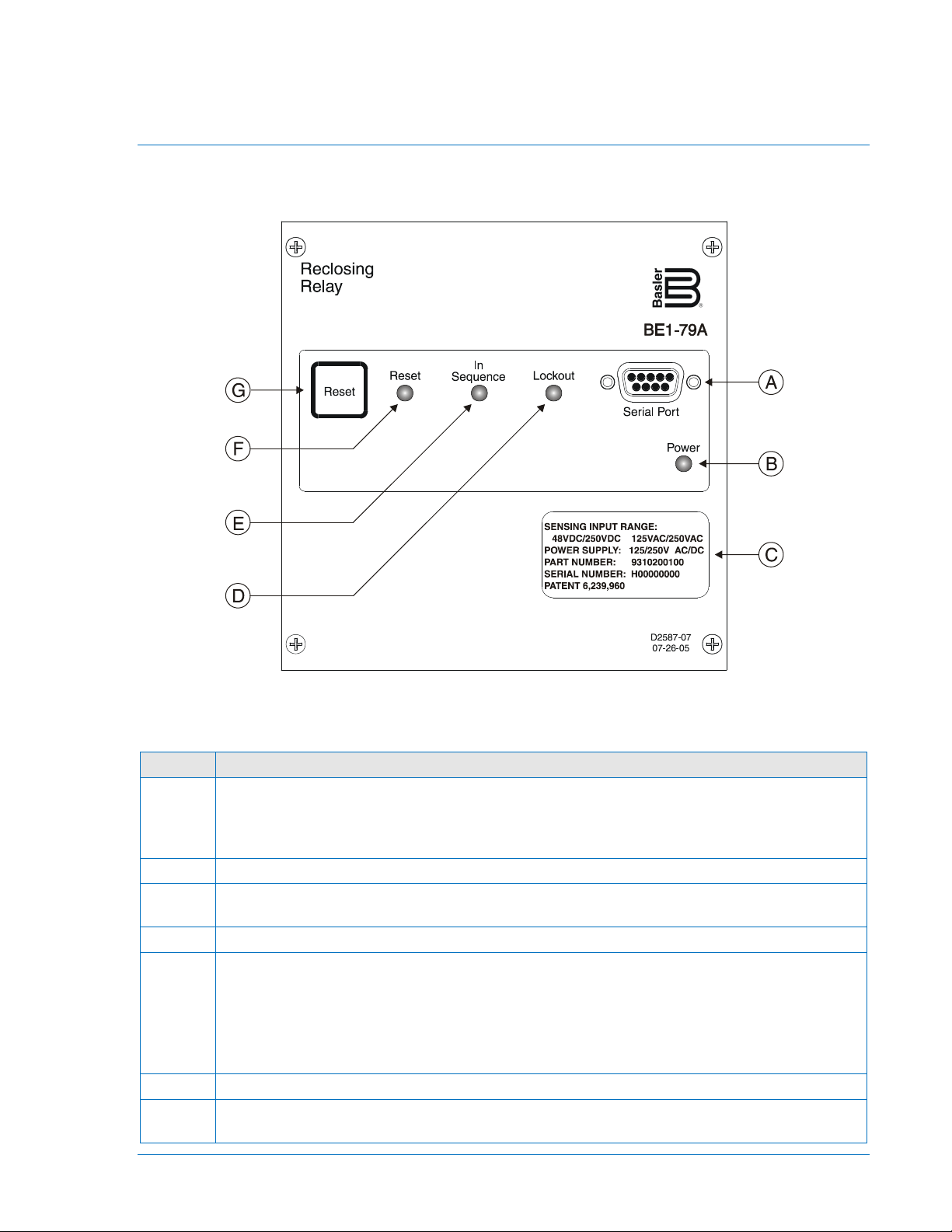
Locator
Description
A
RS-232 Serial Communication Port. A PC or computer terminal running a terminal
ASCII command language.
B
Power LED. A lit Power LED indicates that operating power is applied to the relay.
C
Identification Label. Shows relay information such as the sensing input range, power supply
type, serial number, and part number.
D
Lockout LED. When lit, this LED indicates that the relay is in the lockout state.
E
In Sequence LED. A lit In Sequence LED indicates any one of the following states:
F
Reset LED. When lit, this LED indicates that the relay is in the reset state.
G
Reset Pushbutton. Pressing this momentary switch clears the In Sequence or Lockout LEDs
and restores the relay to the reset state.
Front Panel
Front panel controls and indicators are illustrated in Figure 2-1 and described in Table 2-1. The locators
and descriptions of Table 2-1 correspond to the locators shown in Figure 2-1.
Figure 2-1. Front Panel Controls and Indicators
Table 2-1. Front Panel Control and Indicator Descriptions
emulation program such as Windows® HyperTerminal can be connected to this port so that
relay settings can be read or changed. Communication with the BE1-79A uses a simple
• Timing to reclose
• Timing to reset
• Timing to lockout
• Attempting to reclose
• Attempting to reset
9310200990 Rev J BE1-79A Controls and Indicators 2-1
Page 18
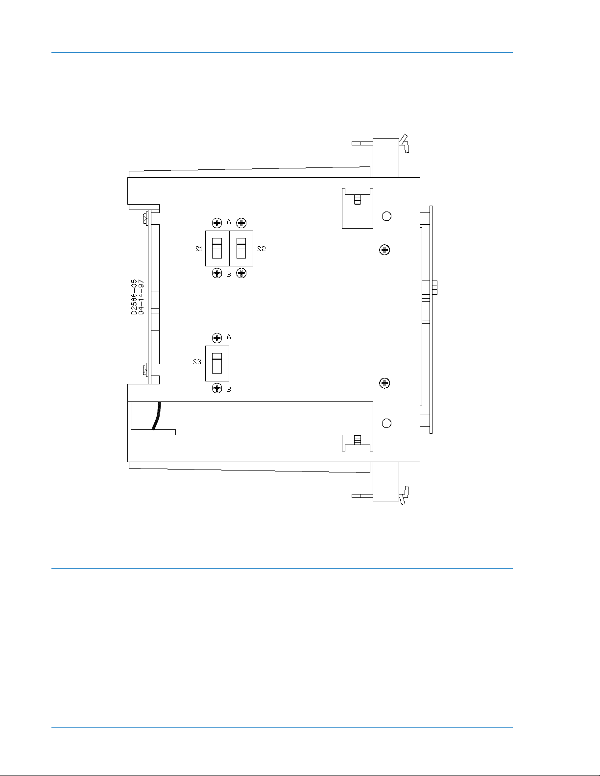
Style Configuration Switches
Three switches on the left side of the relay cradle are used to configure the BE1-79A for either ACR11A
or ACR11B operation. For simplicity, recloser styles ACR11B, ACR11C, ACR11D, ACR11E, and ACR11F
will be referred to as ACR11B throughout this manual. Figure 2-2 illustrates the location of the style
configuration switches. The BE1-79A is delivered with switches S1, S2, and S3 placed in the “A” position.
Figure 2-2. Style Configuration Switches
Instantaneous Reclose Jumper Switch and RS Contact Switch
Two switches on the right side of the relay cradle select either internal or external jumpering for an
instantaneous first reclosure and for selecting normally-closed or normally-open operation of the RS
contact. Switch S4 is used to select internal or external jumpering and switch S5 is used to select
normally-open or normally-closed operation of the RS contact. Figure 2-3 illustrates the location of
switches S4 and S5. The BE1-79A is delivered with switch S4 placed in the “EXT” position and switch S5
placed in the “NC” position.
2-2 BE1-79A Controls and Indicators 9310200990 Rev J
Page 19
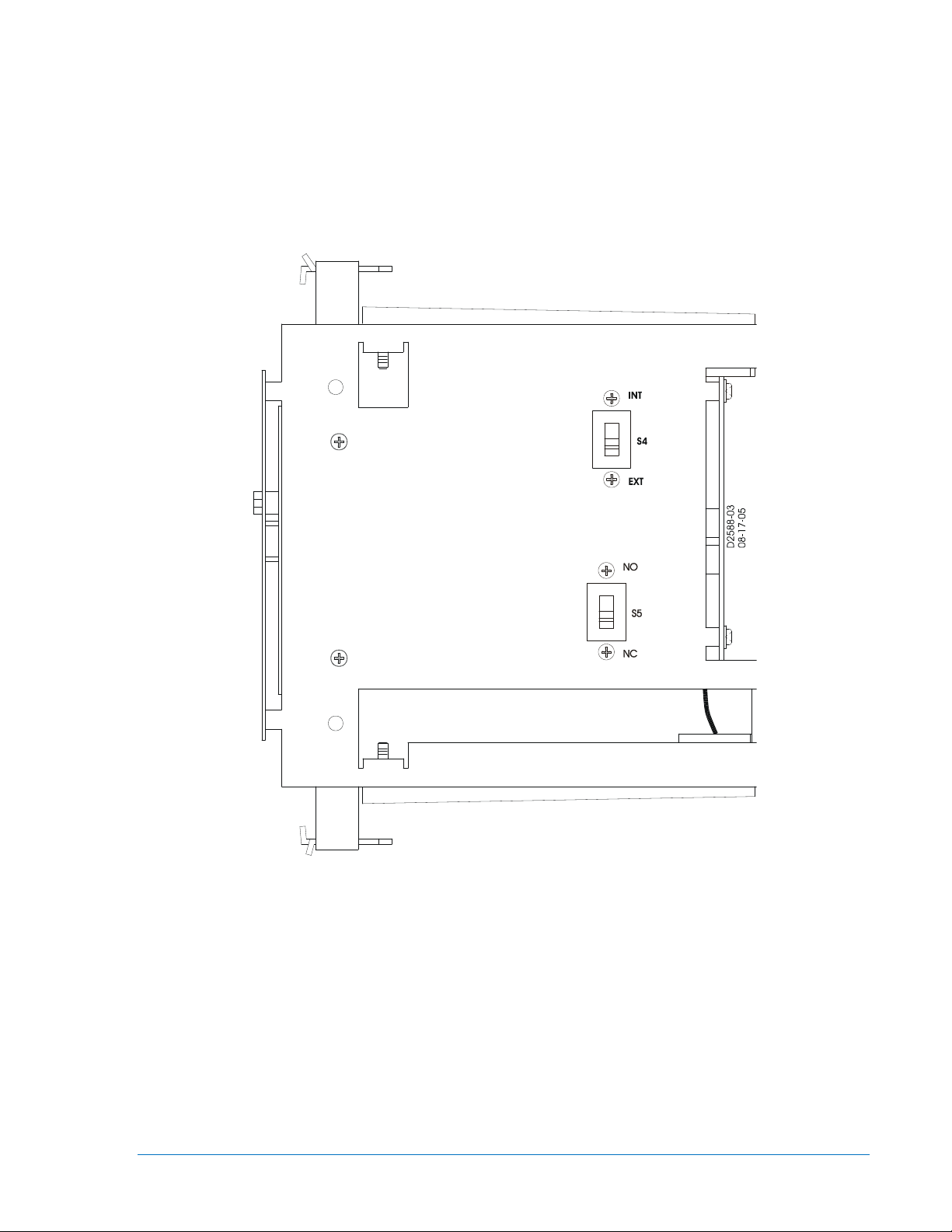
Figure 2-3. Instantaneous Reclose Jumper Switch and RS Contact Selection Switch
9310200990 Rev J BE1-79A Controls and Indicators 2-3
Page 20

2-4 BE1-79A Controls and Indicators 9310200990 Rev J
Page 21

SECTION 3 • FUNCTIONAL DESCRIPTION
TABLE OF CONTENTS
SECTION 3 • FUNCTIONAL DESCRIPTION ........................................................................................... 3-1
Introduction ............................................................................................................................................ 3-1
Hardware ................................................................................................................................................ 3-1
100 Series Description ....................................................................................................................... 3-1
200 Series Description ....................................................................................................................... 3-1
Circuit Operation .................................................................................................................................... 3-1
Inputs .................................................................................................................................................. 3-1
Microprocessor ................................................................................................................................... 3-3
Outputs ............................................................................................................................................... 3-3
Interconnections ..................................................................................................................................... 3-5
Recloser Operation ................................................................................................................................ 3-7
Power-Up............................................................................................................................................ 3-7
Reset .................................................................................................................................................. 3-8
Lockout ............................................................................................................................................... 3-8
Reclosing Sequences ......................................................................................................................... 3-8
Figures
Figure 3-1. Function Block Diagram .......................................................................................................... 3-1
Figure 3-2. Relay Interconnections for ACR11A Applications
Figure 3-3. Relay Interconnections for ACR11B Applications
Figure 3-4. Power-Up Flow Chart
Figure 3-5. Reclose Settings Example
Figure 3-6. Reclosing Flow Chart
................................................................... 3-5
................................................................... 3-6
.............................................................................................................. 3-7
...................................................................................................... 3-9
............................................................................................................ 3-10
Tables
Table 3-1. Contact Sensing Jumpers ........................................................................................................ 3-2
Table 3-2. Contact Sensing Inputs Description for ACR11A Operation
Table 3-3. Contact Sensing Inputs Description for ACR11B Operation
Table 3-4. Outputs Description for ACR11A Operation
Table 3-5. Outputs Description for ACR11B Operation
.................................................... 3-2
.................................................... 3-3
............................................................................. 3-3
............................................................................. 3-4
9310200990 Rev J BE1-79A Functional Description i
Page 22

ii BE1-79A Functional Description 9310200990 Rev J
Page 23

SECTION 3 • FUNCTIONAL DESCRIPTION
V1
V3
V2
V4
V5
MICROPROCESSOR
C1 C3 C5 C7 C9
ISO
ISO
ISO
ISO
ISO
EEPROM
Settings and Status
Memory
RAM
Operating
Memory
ROM
Program
Memory
AC/DC
Power
Reset
Watchdog
Timer Circuit
Power Supply
RS-232
LED
Indicators
D2588-04
08-17-05
C2 C4 C6 C10
C8
S5
Introduction
BE1-79A relays are microprocessor-based devices that provide automatic reclosing of circuit breakers.
This section describes the hardware, circuitry, and software of the BE1-79A.
Hardware
The BE1-79A is supplied as an S1 cradle and case (200 series) or an S2 cradle without a case (100
series).
100 Series Description
The BE1-79A-100 and –101 consist of a draw-out cradle assembly that is intended for installation in an
existing S2 case. A case is not provided with the cradle assembly.
200 Series Description
The BE1-79A-200 and –201 consist of a draw-out cradle assembly with a steel and phenolic case. The
case has the same overall dimensions as a Basler Electric or General Electric S1 case.
Circuit Operation
This description of circuit operation is divided into Inputs, Microprocessor, and Outputs. BE1-79A circuit
functions are illustrated in Figure 3-1 and described in the following paragraphs.
Figure 3-1. Function Block Diagram
Inputs
The four types of BE1-79A inputs are:
• Operating power
• Contact sensing inputs
9310200990 Rev J BE1-79A Functional Description 3-1
• Reset switch
• Serial communication port
Page 24

Operating Power
Jumper Position
Nominal Voltage
1
125 Vdc or 120 Vac
2
48 Vdc
3
250 Vdc or 240 Vac
selectable voltage range should be
Input
Terminals
Description
lockout, a reset will be initiated anytime V1 senses voltage. (E Reset)
V2
7, 8
Connects to a 52b contact, which results in voltage being sensed when the
This prevents multiple reclose attempts for a single reclose setting. (Z)
V3
11, 12
Used to monitor the 52b contact while the relay is in a reset condition. When
V3 senses voltage, the relay initiates a reclose sequence. (E Operate)
V4
—
Not used in this application.
V5
5, 6
Internally connected to the relay power supply terminal. A loss of sensing
contacts to return to their de-energized or “in-the-box” state.
Operating power for the internal circuitry is applied to the internal, isolated, switching power supply. The
power supply operates over a range of 120 to 240 Vac or 125 to 250 Vdc with no connection changes or
jumpers required. The operating power input is not polarity sensitive and is not disrupted by variations in
the supply voltage or frequency over the power supply operating range. The power supply generates a 24
Vdc output.
BE1-79A-101 and BE1-79A-201 relays are equipped with holdup circuitry that maintains relay function for
a minimum of 40 cycles after nominal operating power is removed.
Contact Sensing Inputs
The contact sensing inputs are designated V1, V2, V3, V4, and V5. Each input is optically isolated to
electrically insulate the input from external power sources. Each contact sensing input is rated for 48 to
250 Vdc and 120 to 240 Vac at 45 to 65 hertz.
Inputs V1 through V4 can operate at any one of
three jumper-selectable voltage ranges. Table 3-1
lists the nominal operating voltage for each of the
three jumper positions. Each input has a dedicated
jumper that is located on the digital circuit board.
Jumper P3 controls the operating voltage for V1, P4
controls V2, P5 controls V3 and P6 controls V4.
Instructions for placing each jumper in the desired
position are provided in Section 5, Installation and
Configuration. Input V5 is dedicated to monitoring
the relay power supply input and is not jumper
selectable.
Table 3-1. Contact Sensing Jumpers
NOTE
In certain applications where 240 Vac control voltage is used, control circuit
feedback can occur through system inductive coupling. This feedback can
result in erroneous signals, causing relay operation. If there is potential for
control circuit feedback, the jumperchanged from the 48 Vdc, factory-default setting to a higher value. Selections
are listed in
The function of each input depends on the operating configuration of the relay. Tables 3-2 and 3-3
describe the function of each contact sensing input for each relay configuration. The GE nomenclature
used for each input is provided in parenthesis following each description.
Table 3-2. Contact Sensing Inputs Description for ACR11A Operation
V1 3, 4 Typically connects to a 52a contact, which results in voltage being sensed
Table 3-1.
when the breaker is closed. If V1 senses voltage within three seconds after the
Reset 1, 2, 3, or 4 timer expires, a reset will be initiated. If the relay is in
breaker is open. This input is typically used to provide an anti-pump feature. If
voltage is removed from V2 during a reclose attempt, the anti-pump feature
will prevent a further reclose attempt until the next reclose set time is reached.
voltage at this input causes all necessary data to be stored in memory and all
3-2 BE1-79A Functional Description 9310200990 Rev J
Page 25

Table 3-3. Contact Sensing Inputs Description for ACR11B Operation
Input
Terminals
Description
V1
3,4
Typically connects to a 52a contact, which results in voltage being sensed
lockout, a reset will be initiated anytime V1 senses voltage. (E Reset)
(Motor)
V3
11, 12
Used to monitor the 52b contact while the relay is in a reset condition. When
V3 senses voltage, the relay initiates a reclose sequence. (E Operate)
V4
11, 17
Connects to a 52b contact, which results in voltage being sensed when the
This prevents multiple reclose attempts for a single reclose setting. (Z)
V5
5, 6
Internally connected to the relay power supply terminal. A loss of sensing
Output
Terminals
Description
C1
—
Not used in this application.
reclose sequence, C2 will remain open until the relay returns to reset. (E1)
Descriptions, Alarm Output Command. (JK)
C4
17, 18
Used in conjunction with the anti-pump function. C4 is closed when voltage is
sensed at input V2. (Z2)
C5
19, 20
Used in conjunction with the anti-pump function. C5 is closed when voltage is
sensed at input V2. (Z3)
when the breaker is closed. If V1 senses voltage within three seconds after the
Reset 1, 2, 3, or 4 timer expires, a reset will be initiated. If the relay is in
V2 6, 7 Voltage sensed at this input causes the relay to start a reclose sequence.
breaker is open. This input is typically used to provide an anti-pump feature. If
voltage is removed from V4 during a reclose attempt, the anti-pump feature
will prevent a further reclose attempt until the next reclose set time is reached.
voltage at this input causes all necessary data to be stored in memory and all
contacts to return to their de-energized or “in-the-box” state.
Reset Switch
This momentary-action switch clears the front-panel In Sequence or Lockout LEDs and restores the relay
to a rest condition. The reset switch performs the same function as the manual clutch release on the
General Electric ACR11 relay. Operating power must be applied to terminals 5 and 6 in order for a reset
to occur.
Serial Communication Port
The communication port is a standard RS-232 (DB-9) female connector located on the front panel. This
port provides the means to read and configure BE1-79A settings.
Microprocessor
All reclosing and communication functions are coordinated by the microprocessor. The BE1-79A uses an
eight-bit microprocessor with integral ROM (read-only memory) and RAM (random access memory). The
microprocessor is monitored by a watchdog circuit that resets the microprocessor if a problem is detected.
Outputs
The BE1-79A has 10 outputs. The function of each output depends on the operating configuration of the
relay. Tables 3-4 and 3-5 provide a description of each output for each relay configuration.
Table 3-4. Outputs Description for ACR11A Operation
C2 13, 14 Closed during reset and open when voltage at input V3 is sensed. During a
C3 15, 16 Functions as a programmable alarm contact. It can be set to function as a
relay fail output or a combination relay fail/lockout output. a detailed
explanation is provided in Section 4, Communication Commands, Command
9310200990 Rev J BE1-79A Functional Description 3-3
Page 26

Output
Terminals
Description
C6
17, 20
This Anti-Pump output closes for the duration of reclose timing (time delay
reclosing) except when output C5 closes. If C5 closes, output C6 will only
in the reset position.
C7
15, 20
Anti-pump output. Closes for the duration of reclose timing except if output C6
sensing input V2. ((BC+Z1)∗KL)
Descriptions, RS Contact Setting Command.
C9
—
Not used in this application.
C10
1, 2
Closed during reset and open when a reclose time delay begins. (E4)
Output
Terminals
Description
C1
12, 17
Closes momentarily when voltage is sensed at input V4 and the relay is in a
reset condition. (Z2∗E6)
C2
13, 14
Closed during reset and open when voltage at input V3 is sensed. During a
reclose sequence, C2 remains open until the relay returns to reset. (E1)
C3
15, 16
Functions as a programmable alarm contact. Can be set to function as a relay
Alarm Output Command.
C4
18, 19
Closed any time that the unit is not in reset. (E5)
C5
17, 19
Closes for three seconds after a reclose timer expires. (AB)
sensing input V4. (BC∗Z1)
C7
8, 20
Closed when the relay is in a lockout state. (HI)
C8
9, 10
RS output. Can be configured as a normally open (NO) or normally closed
Application.
C9
5, 8
Closes when the relay is in reset and voltage is sensed at input V3. C9
timing begins or is running. (E4)
close when voltage is sensed at contact sensing input V4. (BC∗Z1) Note: At
reset, operational state of C6 (closed or open) is determined by the first time
delay reclose setting. If first reclose time delay setting is “0”, C6 is open in the
reset position. If first reclose time delay setting is greater than “0”, C6 is open
closes. If C6 closes, output C7 will close only if voltage is sensed at contact
C8 9, 10 RS output. Can be configured as a normally open (NO) or normally closed
(NC) contact. Can be set to energize for an adjustable duration after the start
of a reclose cycle. The interval between the start of the reclose sequence and
C8 energizing is also adjustable. A detailed explanation of programming the
RS output is provided in Section 4, Communication Commands, Command
Table 3-5. Outputs Description for ACR11B Operation
fail output or a combination relay fail/lockout output. a detailed explanation is
provided in Section 4, Communication Commands, Command Descriptions,
C6 14, 17 Anti-pump output. Closes for the duration of reclose timing except if output C5
closes. If C5 closes, output C6 will close only if voltage is sensed at contact
(NC) contact. Can be set to energize for an adjustable duration after the start
of a reclose cycle. The interval between the start of a reclose sequence and
C8 energizing is also adjustable. A detailed explanation of programming the
RS output is provided in Section 4, Communication Commands, Command
Descriptions, RS Contact Setting Command and Appendix A, RS Contact
remains closed until the relay reaches either a lockout or reset condition.
(GH+E3)
C10 1, 2 Closed only during a reset condition. Opens and stays open when a reclose
3-4 BE1-79A Functional Description 9310200990 Rev J
Page 27

Interconnections
11
12
13
14
15
16
17
18
19
20
1
2
3
4
5
6
7
8
9
10
C8
V1
V2
V3
C3
C10
C2
C4
C5
C7
C9
S3
S1
S1
S2
S2
S4
INT EXT
A B
B A
C6
B A
A
B
B A
D2633-06
NC
NO
S5
V5
Power
Supply
RS
D
E
1
1
RS mode electronic selector
switch (SP-79ARS command)
2
2
2
Case-mounted, paddle-operated
shorting bars
Figures 3-2 and 3-3 illustrate the interconnection of the contact sensing inputs, relay outputs, style
configuration switches, instantaneous reclose jumper switch, and RS contact configuration switch in the
BE1-79A relay. The state of all relay output contacts is shown with all power removed from the relay.
Figure 3-2 shows the relay configured for an ACR11A application. Figure 3-3 shows the relay configured
for an ACR11B application with an instantaneous recloser jumper.
9310200990 Rev J BE1-79A Functional Description 3-5
Figure 3-2. Relay Interconnections for ACR11A Applications
Page 28

11
12
13
14
15
16
17
18
19
20
1
2
3
4
5
6
7
8
9
10
C8
V1
V5
V2
V3
V4
C3
C10
C1
C2
C4 C5
C7
C9
S3
S1
S1
S2
S2
S4
INT EXT
A B
B A
C6
B A
A
B
B A
D2633-05
NC
NO
S5
Power
Supply
RS
D
E
1
RS mode electronic selector
switch (SP-79ARS command)
1
2
Case-mounted, paddle-operated
shorting bars
2
2
Figure 3-3. Relay Interconnections for ACR11B Applications
3-6 BE1-79A Functional Description 9310200990 Rev J
Page 29

Reclose
Power-Up
In Reset At
Power-Up
?
Style
Change Prior To
Power-Up?
Restore Power
Down State
Of Relay
Timing To
Lockout
?
Resetting
?
Reset
Timer Expired
?
52A
?
All
Reclose Attempts
Done?
Lockout
Time Reached
?
Lockout
Manual
Reclose
?
Reset
Time Reached
?
Reset
52B
?
Y
Y
Y
Y
N
N
Y
Y
N
Y
N
N
N
N
N
N
N
Y
N
N
Y
Y
Y
D2588-06
05-06-97
Reclose
Time Reached
?
Y
Recloser Operation
Information about the software-controlled features of the recloser is provided in the following paragraphs.
Power-Up
The flow chart of Figure 3-4 describes relay operation following the application of operating power.
Depending on conditions and the reset delay setting, the interval from power application to the resultant
state may be from 0 to 300 seconds.
Figure 3-4. Power-Up Flow Chart
9310200990 Rev J BE1-79A Functional Description 3-7
Page 30

Reset
A reclosing sequence may be initiated only when the relay is in the reset state. Reset is indicated by the
front panel Reset LED. In order for the relay to reach reset, the controlled breaker must be closed during
a three-second period when the reset timer expires. If the breaker opens prior to this time, the relay will
proceed to the next reclosing attempt. If the number of programmed reclosing attempts has been
exhausted, the relay will drive to lockout.
A reset time of zero is used if no reset is desired after a specific reclosing attempt. As an example, for a
first reclose/reset time delay setting of SP-79A1=10,0, the 0 indicates that the BE1-79A will not reset until
after the next non-zero reset time. If the second reclose/reset time delay setting is SP-79A2=30,40, then
the relay will reset at the 40 second point in the timing sequence.
Lockout
Lockout, a state inhibiting relay operation, may be produced by four conditions:
• Reclose failure
• Number of breaker openings exceeds the number of programmed reclosure attempts
• The EXIT command is entered to terminate RS-232 communication
• Communication access has timed out
Lockout is indicated by the front panel Lockout LED. The S-ALM command allows output C3 to be
programmed to close for a lockout condition. Lockout is terminated when the controlled breaker is closed
(manually or by other means) and remains closed for the duration of the final reset time delay setting.
Reclosing Sequences
A reclosing sequence is initiated by the closure of a 52b contact. A reclosing sequence is indicated by the
In Sequence LED located on the front panel. The BE1-79A provides up to four automatic reclosures.
Each reclose setting is adjustable and has a setting range of 0 to 300 seconds. The number of reclosing
attempts may be limited by adjusting any one of the reclose time delay settings (after the first reclose) to
zero. When a breaker trip occurs at this point in the reclosing sequence, the BE1-79A will time toward
lockout. An instantaneous first reclose is enabled on BE1-79A relays configured for ACR11B operation by
an external jumper connected across case terminals 13 and 17 or by switch S4 located on the right side
of the relay cradle.
Each of the four reclose settings has a corresponding reset timer. A final reset controls the time between
lockout and reset. Each reset setting is adjustable and has a setting range of 0 to 300 seconds. Pressing
the front panel Reset pushbutton will clear a reclosing sequence and return the relay to the reset state.
The numbering and labeling of reclose and reset timer settings of Basler reclosing relays such as the
BE1-79 and BE1-79M are based on the breaker opening that immediately precedes each reclose and
reset setting. This is not the case with the BE1-79A. Each reclose and reset timer setting begins at time
zero when the breaker opens the first time and initiates the first reclose timer. Typically, this makes the
first reclose setting the shortest time setting and the fourth reclose setting the longest time setting. Figure
3-5 illustrates a BE1-79A reclosing sequence and the relationship of each reclose setting to the breaker
openings.
The flow chart of Figure 3-6 is a simplified representation of reclosing sequence initiation and
progression.
If a reclosing sequence is interrupted by removing power supply voltage from terminal 5 or 6, this will
“freeze” the timing cycle at that point in the reclosing sequence. Freezing the timing sequence will result
in contact C10 and the RS contact returning to their de-energized state when the BE1-79A power supply
is de-energized. Once voltage is restored to the power supply, timing resumes from the point in the
reclosing sequence that the power supply was de-energized.
External restrictions such as “hot-bus, dead-line” should be connected between terminals 7 and 8 of the
BE1-79A to avoid de-energizing the power supply and “freezing” the timing sequence.
3-8 BE1-79A Functional Description 9310200990 Rev J
Page 31

Time zero begins at
1
st
breaker opening.
Final Reset
= 185 s or 5 s
after manual
close
Reclose 1
= 10 s
10 s
20 s 20 s 20 s
Lockout
= 180 s
180 s
185 s
P0034-01
09-20-05
2nd
Breaker
Opening
3rd
Breaker
Opening
4th
Breaker
Opening
5th
Breaker
Opening
Reclose 2
= 30 s
Reset 1
= 20 s
Reset 2
= 40 s
Reclose 3
= 50 s
Reset 3
= 60 s
Reclose 4
= 70 s
Reset 4
= 80 s
30 s
50 s
70 s
180 s - lockout
Relay Settings
SP-79A1=10,20 SP-79A3=50,60 SP-79ALO=180,185
SP-79A2=30,40 SP-79A4=70,80 SP-ALM=1
0
Figure 3-5. Reclose Settings Example
9310200990 Rev J BE1-79A Functional Description 3-9
Page 32

Reset 2
Time?
Reset
Rec 4
Time?
52B
?
Rec. 1
Time?
52B
?
Issue
Reclose
Signal
52B
?
Reclose
Complete?
Reset 1
Time?
52A
?
Reset
Reset
Complete?
Rec 2
=0?
Perform
Lockout
Rec 2
Time?
52B
?
Issue
Reclose
Signal
52B
?
Reclose
Complete?
52A
?
Reset
Reset
Complete?
Rec 3
=0?
Rec 3
Time?
52B
?
Issue
Reclose
Signal
52B
?
Reclose
Complete?
Reset 3
Time?
52A
?
Reset
Reset
Complete?
Rec 4
=0?
Perform
Lockout
52B
?
Issue
Reclose
Signal
52B
?
Reclose
Complete?
Reset 4
Time?
52A
?
Reset
Reset
Complete?
Perform
Lockout
Perform
Lockout
Lockout
52A
?
Final
Reset
Time?
Reset
Perform
Lockout
Lockout
Time?
Lockout
N
N
N
N
N
N
N
N
N
N
Y
Y
Y
Y
Y
Y
Y
Y
Y
Y
Y
N
Y
N
N
Y
N
Y
Y
N
N
Y
N
Y
N
Y
N
Y
N
Y
Y
N
Y
Y
N
N
Y
N
Y
N
Y
Y
N
Y
N
N
YY
N
N
Y
N
Y
Y
N
D2588-07
05-07-97
N
N
Y
Y
Figure 3-6. Reclosing Flow Chart
3-10 BE1-79A Functional Description 9310200990 Rev J
Page 33

SECTION 4 • COMMUNICATION COMMANDS
TABLE OF CONTENTS
SECTION 4 • COMMUNICATION COMMANDS ...................................................................................... 4-1
Introduction ............................................................................................................................................ 4-1
Communication Port Parameters ........................................................................................................... 4-1
ASCII Command Format ........................................................................................................................ 4-1
Command Format .............................................................................................................................. 4-1
Command Response Format ............................................................................................................. 4-1
Command Descriptions .......................................................................................................................... 4-2
Changing Settings through the Serial Port ......................................................................................... 4-2
Tables
Table 4-1. Internal Default Settings ........................................................................................................... 4-4
9310200990 Rev J BE1-79A Communication Commands i
Page 34

ii BE1-79A Communication Commands 9310200990 Rev J
Page 35

SECTION 4 • COMMUNICATION COMMANDS
Introduction
Communication commands are sent to the BE1-79A through a standard RS-232 (DB-9) connector located
on the front panel. The BE1-79A ASCII communication protocol is compatible with readily available
terminal/modem software such as the HyperTerminal application provided with the Windows® PC
operating system. Information about configuring HyperTerminal and Terminal for communication with the
BE1-79A is provided in Appendix B, Terminal Communication.
Communication Port Parameters
The following parameters apply to the BE1-79A communication port:
• Fixed baud rate of 9600
• Data bits fixed at 8
• Parity is fixed at NONE (N)
• Number of stop bits is fixed at 1
• Half duplex operation is supported
More information about BE1-79A communication interface requirements is provided in Section 5,
Installation and Configuration.
ASCII Command Format
Each communication command, <CMD>, consists of an ASCII string terminated by a carriage return,
<CR>. A line feed, <LF>, is optional.
Command Format
The BE1-79A uses a command format of <CMD>[<;>CMD…]<CR>[LF>]. Command components are
defined as follows.
[ ] Brackets identify optional parameters. The brackets are not part of the command.
< > Separators are used for clarity. The separators are not part of the command.
CMD <name>[n][<=><setting-x>…[<,><setting-x>]]
Where:
Name Command name. Refer to Command Descriptions for more information.
N Optional command object. If more than one object is available and n is omitted, the
command applies to all objects.
= Used to indicate that the command is to change data or settings.
Setting-x Command setting(s)
, Commas are used as setting separators
CR A carriage return is used to end a command and start command execution.
LF A line feed may be used for clarity. It is ignored by the relay.
Spaces One or more spaces may be added between entries for clarity if desired.
Command Response Format
The BE1-79A uses a command response format of [<response>][<ACK>]. Command components are
defined as follows.
response Determined by CMD.
ACK “>” is returned for a valid command, “?” is returned for an invalid command.
Commands received by the BE1-79A consist of two types: requests for information and changes to
operating parameters. Commands to change parameters are identified by and equal sign (=). The
operating parameters to the right of the equal sign are intended to replace the current operating
parameters related to the command.
Some commands may pertain to multiple items. In that case, a numeric identifier is used after the
command name to specify a single item. If the identifier is omitted, the command is applied to all possible
9310200990 Rev J BE1-79A Communication Commands 4-1
Page 36

items. For example, the SP-79A1 command could be used to read the first reclose setting or the
command S could be used to read all reclose settings.
Command Descriptions
BE1-79A command descriptions and examples are provided in the following paragraphs.
Changing Settings through the Serial Port
The ACCESS command is used to access write privileges while changing relay settings. Relay control
functions are disabled when access is granted. Changing the settings through the serial port requires that
the operator use the ACCESS command to obtain programming access. The operator enters ACCESS=
and the relay responds with an acknowledgement of ACCESS GRANTED if the command was received
and executed. Any time an invalid command is received, the relay will respond with a question mark (?).
The EXIT command is used to release write privileges while changing relay settings. After the changes
are made, the new data will be copied to the working settings and saved to nonvolatile memory when
EXIT is entered. The operator must confirm that the programming is completed and accepted before the
changes are actually made. It is important to make all changes to relay settings before executing the EXIT
command. This ensures that all intended settings are executed. The relay will go to the lockout state after
the EXIT command is entered. If voltage is sensed at V1, the relay will return to the reset state after the
lockout timer expires.
Changing settings through the serial port consists of the following sequence:
1. Enter ACCESS=<CR> or A=<CR>.
2. Enter the necessary commands to change the current settings.
3. Enter EXIT<CR> or E<CR> to clear access and save settings.
4. Enter Y (yes)<CR> to confirm save. Enter N (no) to continue using the old settings.
The <CR> characters placed after commands represent a carriage return or pressing the Enter key. For
simplicity, they will no longer be shown. However, each line entered by the operator must be terminated
with a carriage return <CR> or a carriage return–line feed <CR–LF>.
Access Command
ACCESS Command
Purpose: Read/set programming access in order to change user settings.
Syntax: ACCESS[=] or A[=]
Access must be changed by entering ACCESS= before any changes to the settings can be made. Relay
protection functions are disabled when access is granted. The ACCESS command is valid for a period of
five minutes if no new characters are entered. ACCESS by itself may be used to check if programming
access is active or disabled. The relay will respond with ACCESS GRANTED or ACCESS: NO. The
available access privilege is Privilege S: Setting Access. When exiting programming access, the relay will
go to the lockout state after the EXIT command is entered. If voltage is sensed at V1, the relay will return
to the reset state after the lockout timer expires.
Exit Command
EXIT Command
Purpose: Exit programming mode
Syntax: EXIT or E
Comments: Exits the programming mode and resets the programming access privilege to 0.
Changes are made to a scratchpad copy of the settings. After the changes are made, the new data will be
saved to nonvolatile memory and the new, working settings will be initialized when control to make
changes is released by entering the EXIT command. After entering EXIT, the user is prompted to confirm
that the new data should be saved. The user has three options (Y or N or C). If Y is entered, the data will
be saved. If N is entered, the changes will be cleared and the old settings will be restored. If C is entered,
the EXIT command will be aborted and programming may continue. It is important to make all changes to
relay parameters before executing the EXIT command. This ensures that all intended settings are
executed.
4-2 BE1-79A Communication Commands 9310200990 Rev J
Page 37

For clarity in the examples, relay responses are printed in the Courier typeface.
EXIT command example: exit after making setting changes.
EXIT
>SAVE CHANGES (Y/N/C)? Prompt to save (Y)es, discard changes (N)o, or (C)ontinue
>Y Confirmation to save changes
CHANGES SAVED Confirmation that changes were saved
Obtaining Help Information Through the Serial Port
The HELP or H command provides general help information on command syntax and functionality when
the manual is not available. Help is available only when the relay is in a reset state.
HELP Command
Purpose: Obtains help on using serial port commands.
Syntax: HELP or H
Comments: The HELP command returns a listing of all available commands along with the proper
syntax for each command.
Obtaining a Summary of All Settings
All relay settings may be listed using the S command.
S Command
Purpose: Read all relay settings back to user.
Syntax: SP-79A[n]
Comments: S by itself may be used to read all relay settings. SP-79A[n] is used to read a specific
setting. the S command can be used to make a record of the relay settings after they have
been set.
S command example: Obtain a report of the relay settings.
A=
S
SP-79A1 5,10
SP-79A2 15,20
SP-79A3 25,30
SP-79A4 35,40
SP-79ALO 45,50
SP-79ARS D,0,5
SP-ALM 2
>
Reclose and Reset Timer Setting Command
SP-79A Command
Purpose: Read or change the reclose and reset timer settings.
Syntax: S[-79a[n][=<reclose time delay>,<reset time delay>]
Comments: n: reclose number of LO for lockout. See Table 4-1 for setting defaults.
reclose time delay: adjustable from 0 to 300 seconds in 0.1 second steps. A Reclose 1
setting of zero will cause an instantaneous first reclosure. A setting of zero for any other
reclose time delay will disable the reclose shot.
reset time delay: adjustable from 0 to 300 seconds in 0.1 second steps. A reset time delay
setting of zero will cause the reset to be disabled. A reset time delay setting less than the
reclose time setting will cause an immediate reset following the reclose attempt.
SP-79A command example: Read the second reclose and reset timer settings.
A=
SP-79A2
15.0,20.0
>
9310200990 Rev J BE1-79A Communication Commands 4-3
Page 38

Lockout Timer Setting Command
Command
Default
SP-79A1
0.0,0.0
SP-79A2
0.0,0.0
SP-79A3
0.0,0.0
SP-79A4
0.0,0.0
SP-79ALO
0.0,15.0
SP-79ARS
E,1.5,15.0
SP-ALM
2
SP-79ALO Command
Purpose: Read or change the lockout timer settings.
Syntax: SP-79ALO[=<lockout time delay>,<final reset time delay>]
Comments: lockout time delay: adjustable from 0 to 300 seconds in 0.1 second increments. A lockout
time delay setting of zero will cause an instantaneous lockout when the breaker opens. A
lockout time delay setting that is shorter than a reclose time delay setting will take priority
and drive the relay to lockout.
Final reset time delay: adjustable from 0 to 300 seconds in 0.1 second increments. A final
reset time delay that is equal to zero or is less than the lockout time delay setting will give
an immediate reset following lockout and a manual reclose. See Table 4-1 for setting
defaults.
Table 4-1. Internal Default Settings
RS Contact Setting Command
SP-79ARS Command
Purpose: Read or change the RS contact settings.
Syntax: SP-79ARS[=<mode>,<apply time>,<remove time>]
Comments: mode: the state of the RS coil and contact, which can be D or E for the coil status.
D: de-energized RS coil. Second NO contact when terminals 5 and 6 are de-energized.
E: energized RS coil. Second NC contact when terminals 5 and 6 are energized.
apply time: time from the start of the reclose cycle until the RS contact is applied. The apply
time is adjustable from 0 to 300 seconds in 0.1 second increments.
remove time: time from the start of the reclose cycle until the RS contact is removed. The
remove time is adjustable from 0 to 300 seconds in 0.1 second increments. See Table 4-1
for setting defaults.
Refer to Appendix A for SP-79ARS command examples.
Alarm Output Command
SP-ALM Command
Purpose: Read or change the Lockout/Relay Fail output setting.
Syntax: SP-ALM[=<mode>]
Comments: mode: selects the operating mode of the alarm output, which can be 1 or 2.
1 selects Relay Fail
2 selects Relay Fail and Lockout (default setting)
Relay Information Command
RG-VER Command
Purpose: Read information about relay hardware/firmware configuration
Syntax: RG-VER
Comments: Transmitting the RG-VER command will cause the relay to respond with the relay model
number and the firmware version and date.
4-4 BE1-79A Communication Commands 9310200990 Rev J
Page 39

SECTION 5 • INSTALLATION AND
CONFIGURATION
TABLE OF CONTENTS
SECTION 5 • INSTALLATION AND CONFIGURATION .......................................................................... 5-1
General .................................................................................................................................................. 5-1
Mounting ................................................................................................................................................ 5-1
Connections ........................................................................................................................................... 5-1
Application.............................................................................................................................................. 5-1
Style Configuration Switches ............................................................................................................. 5-1
Instantaneous Reclose Jumper Switch .............................................................................................. 5-1
RS Switch ........................................................................................................................................... 5-1
Motor Voltage ..................................................................................................................................... 5-7
Contact Sensing Inputs ...................................................................................................................... 5-7
Timing Cams ...................................................................................................................................... 5-8
Fault Clearing ..................................................................................................................................... 5-8
RS Contact ......................................................................................................................................... 5-8
Alarm Output ...................................................................................................................................... 5-8
Reset Switch ...................................................................................................................................... 5-9
Relay Installation .................................................................................................................................... 5-9
Communication Connections and Settings ............................................................................................ 5-9
Communication Connector ................................................................................................................. 5-9
Communication Settings .................................................................................................................. 5-10
Figures
Figure 5-1. Overall Dimensions, S1 Case ................................................................................................. 5-2
Figure 5-2. Panel Cutout Dimensions, S1 Case
Figure 5-3. Terminal Connections, Rear View, S1 Case
Figure 5-4. Typical Connections for ACR11A Application
Figure 5-5. Typical Connections for ACR11B Application
Figure 5-6. Contact Sensing Jumpers ....................................................................................................... 5-7
Figure 5-7. Contact Sensing Jumper Locations
Figure 5-8. PC to BE1-79A Connections
Tables
Table 5-1. RS-232 Pin Functions .............................................................................................................. 5-9
........................................................................................ 5-3
........................................................................... 5-4
......................................................................... 5-5
......................................................................... 5-6
........................................................................................ 5-7
................................................................................................. 5-10
9310200990 Rev J BE1-79A Installation and Configuration i
Page 40

ii BE1-79A Installation and Configuration 9310200990 Rev J
Page 41

SECTION 5 • INSTALLATION AND
CONFIGURATION
General
BE1-79A Reclosing Relays are delivered in sturdy cartons to prevent shipping damage. Upon receipt of a
relay, check the model number against the requisition and packing list for agreement. Inspect for damage
and, if there is evidence of such, file a claim with the carrier and notify the Basler Electric regional sales
office, your sales representative, or the Technical Sales Support department of Basler Electric.
If the relay is not installed immediately, store it in the original shipping carton in a moisture- and dust-free
environment.
Mounting
Because the BE1-79A is of solid-state design, it does not have to be mounted vertically. Any convenient
mounting angle may be chosen. The BE1-79A is available in an S2 cradle or an S1 cradle with case. The
S2 cradle is intended for installation in an existing S2 case. Overall dimensions for the S1 case are shown
in Figure 5-1. S1 case cutout dimensions are shown in Figure 5-2.
Connections
Incorrect wiring may result in damage to the relay. Be sure to use the correct input power for the power
supply and the correct input voltage for the contact inputs. Connections should be made with a minimum
wire size of 14 AWG. Figure 5-3 illustrates the terminal connections of the S1 case. Figure 5-4 provides a
typical connection diagram for an application using an ACR11A style relay. Figure 5-5 shows typical
connections for an application using an ACR11B style relay.
Application
The intended function of the BE1-79A Reclosing Relay is to duplicate an ACR11 recloser with only minor
variations. To ensure that your BE1-79A relay functions properly, you should consider the adjustments
and settings described in the following paragraphs.
Style Configuration Switches
Switches S1, S2, and S3 must be set properly for your application. All three switches should be placed in
the A (up) position for ACR11A operation. All three switches should be placed in the B (down) position for
ACR11B, ACR11C, ACR11E, and ACR11F operation.
Instantaneous Reclose Jumper Switch
Use the following guidelines when setting Instantaneous Reclose Jumper Switch S4.
• For ACR11a operation, switch S4 should be placed in the EXT (down) position.
• An ACR relay has a red jumper from terminals 13 to 17 for an instantaneous first reclosure
(SP-79A1 0.0,X.X) is duplicated by placing BE1-79A switch S4 in the INT (up) position.
• A delayed first reclosure is achieved when S4 is placed in the EXT (down) position and the external
jumper is removed from terminals 13 and 17.
• If an external jumper is left in place at terminals 13 and 17 for an instantaneous first reclosure, S4
should be placed in the EXT (down) position.
• Neither an internal nor an external jumper is required at terminals 12 and 13 for a delayed first
reclosure. Switch S4 should be placed in the EXT (down) position for delayed reclosures.
RS Switch
RS switch S5 is used to control the RS contact for normally open or normally closed contact configuration.
Figure 2-2 and 2-3 should be consulted for the location and setting positions of the style and configuration
switches.
9310200990 Rev J BE1-79A Installation and Configuration 5-1
Page 42

Figure 5-1. Overall Dimensions, S1 Case
5-2 BE1-79A Installation and Configuration 9310200990 Rev J
Page 43

Figure 5-2. Panel Cutout Dimensions, S1 Case
9310200990 Rev J BE1-79A Installation and Configuration 5-3
Page 44

D2588-17
06-05-97
Figure 5-3. Terminal Connections, Rear View, S1 Case
5-4 BE1-79A Installation and Configuration 9310200990 Rev J
Page 45

Figure 5-4. Typical Connections for ACR11A Application
9310200990 Rev J BE1-79A Installation and Configuration 5-5
Page 46

Figure 5-5. Typical Connections for ACR11B Application
5-6 BE1-79A Installation and Configuration 9310200990 Rev J
Page 47

Motor Voltage
No adjustment is required for the motor voltage applied at terminals 5 and 6. The applied voltage can
range from 120 to 240 Vac or 125 to 250 Vdc. These terminals serve as the input to the BE1-79A power
supply and control functions.
Contact Sensing Inputs
Energizing levels for contact sensing inputs V1 through
V4 are jumper selectable for operation at three nominal
voltage levels. Jumper P3 controls the operating voltage
for V1, P4 controls V2, P5 controls V3, and P6 controls
V4. Nominal voltage levels of 125 Vdc/120 Vac, 48 Vdc,
or 250 Vdc/240 Vac may be selected. Figure 5-6
illustrates the three possible jumper positions for P3
through P6. Input V5 is dedicated to monitoring the relay
power supply input and is not jumper selectable.
Figure 5-6. Contact Sensing Jumpers
NOTE
In certain applications where 240 Vac control voltage is used, control circuit
feedback can occur through system inductive coupling. This feedback can
result in erroneous signals, causing relay operation. If there is a potential for
control circuit feedback, the jumper selectable voltage range should be
changed from the 48 Vdc factory default setting to a higher position. Selections
are provided in Table 3-1.
The following paragraphs describe how to locate and change the position of the contact-sensing jumpers.
1. Remove the four Phillips screws from the front panel and separate the front panel from the relay
chassis.
2. Carefully grasp and remove the Digital circuit board (top circuit board) from the relay chassis. Take
care not to damage any of the circuit board components. Observe all electrostatic discharge (ESD)
precautions when handling the circuit board. Place the circuit board on an ESD-safe surface.
3. Locate the four jumper terminal blocks (P3 through P6) on the circuit board. The jumper terminal
blocks are located on the component side of the circuit board near the rear contact fingers (see
Figure 5-7). Each terminal block has three pins and each jumper is factory installed on pins 2 and 3.
Figure 5-6 illustrates each of the three jumper positions.
Figure 5-7. Contact Sensing Jumper Locations
4. To select operation at 125 Vdc or 120 Vac, remove the jumper from pins 2 and 3 and position it on
pins 1 and 2. To select operation at 250 Vdc or 240 Vac, remove the jumper from pins 2 and 3 and
position it on pin 3 for storage. (Only pin 3 of the terminal block should be covered.)
9310200990 Rev J BE1-79A Installation and Configuration 5-7
Page 48

5. When all of the jumpers are positioned for operation in the desired sensing voltage range, prepare to
place the circuit board back in the relay chassis.
6. Align the circuit board edges with the white guide markings on the relay chassis. Once aligned, slide
the circuit board back into the chassis until the circuit board is seated in its connector. The front of the
circuit board should be flush with the front of the relay chassis. (The LEDs and serial port connector
will protrude past the front of the chassis.)
7. Place the front panel on the front of the relay chassis and align the four screw holes. Secure the front
panel to the relay chassis with the four Phillips screws removed in step 1.
Timing Cams
Double-ended cams on ACR reclosers provide a 10 second reset after a reclosure. Single-ended cams
can be adjusted for any reclose or reset time desired. The single- and double-ended cams of the ACR
reclosers are simulated with the reclose and reset timer settings of the BE1-79A relay. Since the reclose
and reset times for each of the four recloses is independently programmable, the function of the ACR
reclosers can be duplicated.
NOTE
A reclose time delay must be set for a duration that is longer than the
preceding reset time delay. Setting the reset time delay longer than the next
reclose time delay in the reclose sequence will give undesired results.
Example:
SP-79A1=0,15 SP-79A1=0,7
SP-79A2=10,15 SP-79A2=10,15
Incorrect
Correct
Fault Clearing
The BE1-79A allows the first reclose to be delayed slightly so that faults may de-ionize before a reclosure
is initiated. Faults typically are allowed to de-ionize for approximately 217 milliseconds (13 cycles) for
distribution voltages and 300 milliseconds (18 cycles) for transmission voltages (including breakeroperating time). The inherent delay of the BE1-79A relay is 22 to 48 milliseconds when set at a time delay
of zero. The reclose timers may be adjusted in increments of 0.1 seconds, which is 6 cycles on a 60-hertz
system.
It is possible to set an ACR recloser for an instantaneous reclose with no voltage applied at terminals 5
and 6. If this unusual application is employed, the user must confirm that voltage is applied to BE1-79A
terminals 5 and 6 when a reclose is desired. Terminals 5 and 6 must be energized for a reclose to be
initiated.
The power holdup circuit of part number 9310200101 relays maintains relay function for a minimum of 40
cycles (667 milliseconds) after nominal operating power is removed. This prevents the relay output
contacts from dropping out too quickly in applications where output C10 is used as an instantaneous trip
enable contact.
RS Contact
A jumper is used in ACR reclosers to configure the RS contact for normally open or normally closed
operation. In the BE1-79A, the RS contact is configured by switch S5. The SP-79RS command allows the
RS contact operate and reset time to be programmed. Refer to Section 4, Communication Commands,
Command Descriptions for a detailed description of the SP-79RS command.
Alarm Output
The SP-ALM command is used to program the alarm output to function as a relay fail output or a
combination relay fail/lockout output. As a relay fail output, the alarm output will close if relay operating
power is lost. The alarm output will also close if the microprocessor detects an abnormal condition such
as:
• The BE1-79A is configured for ACR11A operation but recognizes inputs that indicate the relay is
operating in an ACR11B system.
• The microprocessor is unsuccessful at storing settings in EEPROM.
5-8 BE1-79A Installation and Configuration 9310200990 Rev J
Page 49

If the microprocessor closes the alarm output due to a failure, all three front panel LED indicators will be
Pin
Function
Name
Direction
1
Shield
—
N/A 2 Transmit Data
TXD
From Relay
3
Receive Data
RXD
Into Relay
4
N/C
—
N/A 5 Signal Ground
GND
N/A 6 N/C
—
N/A
7
N/C
—
N/A
8
N/C
—
N/A 9 N/C
—
N/A
lit. The failure indication can be cleared by cycling operating power to the relay.
Refer to Section 4, Communication Commands, Command Descriptions for a detailed description of the
SP-ALM command.
Reset Switch
The front panel reset switch performs the same function as the manual clutch release in ACR reclosers.
Power must be applied to terminals 5 and 6 for this function to perform a reset.
Relay Installation
Perform the following procedure to install the BE1-79A relay.
1. Adjust Style Configuration Switches S1, S2, and S3 and Instantaneous Reclose Jumper Switch S4 to
the correct positions for your application.
2. Insert the BE1-79A relay and close the cradle latches to lock the relay into the case.
3. Install the connection plugs.
4. Enter the desired settings through the front serial communication port. Information about configuring
HyperTerminal and Terminal for communication with the BE1-79A is provided in Appendix B,
Terminal Communication. Refer to Section 4, Communication Commands for information about relay
communication and ASCII commands.
5. Install the relay cover.
Communication Connections and Settings
The required connections and settings for BE1-79A communication are described in the following
paragraphs.
Communication Connector
The BE1-79A uses a standard RS-232 (DB-9) female connector located on the front panel. Connector pin
numbers, functions, names, and signal directions are listed in Table 5-1. Figure 5-8 provides a connection
diagram for connecting the BE1-79A relay to a personal computer (PC).
Table 5-1. RS-232 Pin Functions
NOTE
The RS-232 communication ports are not equipped with request-to-send
(RTS) and clear-to-send (CTS) control lines. This makes the BE1-79A
incompatible with systems that require hardware handshaking or systems that
use self-powered RS-232 to RS-485 converters connected to the RS-232
ports.
9310200990 Rev J BE1-79A Installation and Configuration 5-9
Page 50

Figure 5-8. PC to BE1-79A Connections
Communication Settings
Communication settings are the formal set of conventions controlling the format and relative timing of
message exchange between two communication terminals. The BE1-79A settings are fixed at 9600, 8N1,
where 9600 is the baud rate, 8 is the number of data bits, N is the parity (none), and 1 indicates one stop
bit. Since the communication settings of the relay are fixed, you must adjust your communication program
settings to match the relay settings. Information about configuring Windows® HyperTerminal for
communication with the BE1-79A is provided in Appendix B, Terminal Communication.
5-10 BE1-79A Installation and Configuration 9310200990 Rev J
Page 51

SECTION 6 • TESTING
TABLE OF CONTENTS
SECTION 6 • TESTING ............................................................................................................................ 6-1
Introduction ............................................................................................................................................ 6-1
Instantaneous Reclose Testing.............................................................................................................. 6-1
ACR11A Style .................................................................................................................................... 6-1
ACR11B Style .................................................................................................................................... 6-1
ACR11A and ACR11B Styles ............................................................................................................ 6-1
Delayed Reclose Testing ....................................................................................................................... 6-2
ACR11A Style .................................................................................................................................... 6-2
ACR11B Style .................................................................................................................................... 6-2
ACR11A and ACR11B Styles ............................................................................................................ 6-2
Power Holdup Circuit Testing ................................................................................................................ 6-5
Part Numbers 9310200101 and 9310200201 .................................................................................... 6-5
Troubleshooting Tips ............................................................................................................................. 6-5
Blinking LEDs ..................................................................................................................................... 6-5
All LEDs On ........................................................................................................................................ 6-5
Figures
Figure 6-1. Test Connections for ACR11A Style Relays ........................................................................... 6-3
Figure 6-2. Test Connections for ACR11B Style Relays ........................................................................... 6-4
Tables
Table 6-1. Instantaneous Reclose Testing Commands ............................................................................ 6-1
Table 6-2. Delayed Reclose Testing Commands
...................................................................................... 6-2
9310200990 Rev J BE1-79A Testing i
Page 52

ii BE1-79A Testing 9310200990 Rev J
Page 53

SECTION 6 • TESTING
Command
Time Between Recloses
ACCESS=<cr>
N/A
SP-79A1=0.0,5.0<cr>
0 – 0 = 0s
SP-79A2=10.0,15.0<cr>
10 – 0 = 10s
SP-79A3=20.0,25.0<cr>
20 – 10 = 10s
SP-79A4=30.0,35.0 <cr>
30 – 20 = 10s
SP-79ALO=40.0,45.0<cr>
40 – 30 = 10s
SP-79ARS=D,19.39,0<cr>
N/A
EXIT<cr>
N/A
Y<cr>
N/A
Introduction
You may prefer to test your relay before installation. To test BE1-79A relay functionality, perform the
procedures in the following paragraphs. Figure 6-1 illustrates the necessary connections for testing relays
configured for ACR11A style operation. The connections diagram for testing relays configured for
ACR11B operation is provided in Figure 6-2.
NOTE
The following test procedures specify 120 Vac for relay power and the contact
sensing inputs. Therefore, contact sensing jumpers P3, P4, P5, and P6 must
be set in position 1 or position 2. The contact sensing circuitry will not function
with 120 Vac applied and the contact-sensing jumpers setting position 3.
Instantaneous Reclose Testing
ACR11A Style
Place Relay Style Configuration switches S1, S2, and S3 in the A position. Place Instantaneous Reclose
Jumper switch S4 in the EXT position. Place RS Contact switch S5 in the NO position.
ACR11B Style
Place Relay Style Configuration switches S1, S2, and S3 in the B position. Place Instantaneous Reclose
Jumper switch S4 in the INT position. Place RS Contact switch S5 in the NO position.
ACR11A and ACR11B Styles
1. Place Test switch S1 in the 52a position and apply 120 Vac to the relay and test circuit.
2. Connect a PC with a serial port and suitable communication software to the relay serial port. Transmit
the settings of Table 6-1 to the relay.
Table 6-1. Instantaneous Reclose Testing Commands
3. Place Test switch S1 in the 52b position and observe that the following sequence of events occur.
a. Front panel Reset LED turns off
b. Reset indicator L1 turns off
c. Front panel In Sequence LED lights
d. Reclose indicator L2 will light immediately and remain lit for three seconds
e. After 10 seconds, L2 will light for three seconds
9310200990 Rev J BE1-79A Testing 6-1
Page 54

f. After 20 seconds, L2 will light for three seconds
Command
Time Between Recloses
ACCESS=<cr>
N/A
SP-79A1=10.0,20.0<cr>
10 – 0 = 10 s
SP-79A2=30.0,40.0<cr>
30 – 10 = 20 s
SP-79A3=50.0,60.0<cr>
50 – 30 = 20 s
SP-79A4=70.0,80.0 <cr>
70 – 50 = 20 s
SP-79ALO=180,185<cr>
180 – 70 = 110 s
SP-79ARS=D,10,9<cr>
N/A
EXIT<cr>
N/A
Y<cr>
N/A
g. After 30 seconds, L2 will light for three seconds
h. After 40 seconds, the front panel Lockout led and Lockout indicator L3 will light
4. Place Test switch S1 in the 52a position and observe that after five seconds, the front panel Reset
LED and Reset indicator L1 light.
5. Place Test switch S1 in the 52b position. When Reclose indicator L2 lights, momentarily place Test
switch S1 in the 52a position and verify that L2 turns off.
6. Place Test switch S1 in the 52b position and verify that after 10 seconds, L2 lights for three seconds.
7. Place Test switch S1 in the 52a position and verify that after 15 seconds, the front panel Reset LED
and Reset Indicator L1 light.
Delayed Reclose Testing
ACR11A Style
Place Style Configuration switches S1, S2, and S3 in the A position. Place Instantaneous Reclose
Jumper switch S4 in the EXT position. Place RS Contact switch S5 in the NO position.
ACR11B Style
Place Style Configuration switches S1, S2, and S3 in the B position. Place Instantaneous Reclose
Jumper switch S4 in the EXT position. Place RS Contact switch S5 in the NO position.
ACR11A and ACR11B Styles
1. Place Test switch S1 in the 52a position and apply 120 Vac to the relay and test circuit.
2. Connect a PC with a serial port and suitable communication software to the relay serial port. Transmit
the settings of Table 6-2 to the relay. (These settings correspond to the illustration of Figure 3-5.)
Table 6-2. Delayed Reclose Testing Commands
3. Place Test switch S1 in the 52b position and observe that the following sequence of events occur.
a. Front panel Reset LED turns off
b. Reset indicator L1 turns off
c. Front panel In Sequence LED lights
d. After 10 seconds, Reclose indicator L2 will light for three seconds
e. After 30 seconds, L2 will light for three seconds
f. After 50 seconds, L2 will light for three seconds
g. After 70 seconds, L2 will light for three seconds
h. After 180 seconds, the front panel Lockout led and Lockout indicator L3 will light
4. Place Test switch S1 in the 52a position and observe that after five seconds, the front panel Reset
LED and Reset indicator L1 light.
5. Place Test switch S1 in the 52b position. When Reclose indicator L2 lights 10 seconds later, place S1
in the 52a position momentarily and verify that Reclose indicator L2 turns off.
6-2 BE1-79A Testing 9310200990 Rev J
Page 55

L3
L2
L1
Reclose
Lockout
Reset
S1
52A
52A
52B
52B
120 Vac
A
B
C
Auxiliary Contact - Closed in Reset
RS Contact - Closes, opens at time set by user
Instantaneous First RecloseContact closes when terminal 7 is energized
Delayed First Reclose
External Jumpers
BE1-79A
1 2 3 4 5 6 7 8 9 10
11 12 13 14 15 16 17 18 19 20
B
C
A
D2588-08
08-01-05
(Front view. For making connections
with GE XLA test plugs.)
NC
NO
S5
6. Place Test switch S1 in the 52b position before 20 seconds elapse and verify that after 30 seconds,
Reclose indicator L2 lights for three seconds.
7. Place Test switch S1 in the 52a position and verify that after 40 seconds, the front panel Reset LED
and Reset indicator L1 light.
9310200990 Rev J BE1-79A Testing 6-3
Figure 6-1. Test Connections for ACR11A Style Relays
Page 56

RS Contact - Closes, opens at time set by user
BE1-79A
1 2
3 4 5 6 7 8
11 12 13 14 15 16 17 18
19 20
A
L1
L2
S1
52A
52B
L3
120 Vac
A
B
Auxiliary Contact - Closed in Reset
Optional Reclose Output
Reset
Lockout
Reclose
D2588-09
08-01-05
9 10
B
NC
NO
S5
(Front view. For making connections
with GE XLA test plugs.)
6-4 BE1-79A Testing 9310200990 Rev J
Figure 6-2. Test Connections for ACR11B Style Relays
Page 57

Power Holdup Circuit Testing
Power holdup circuit testing applies only to BE1-79 relays with part numbers 9310200101 and
9310200201.
Part Numbers 9310200101 and 9310200201
Remove 120 Vac operating power from terminals 5 and 6. Measure the time from when the operating
power is removed until the RS contacts (terminals 9 and 10) close. The time should be 1.3 seconds or
greater.
Troubleshooting Tips
The front panel LED indicators will annunciate certain conditions that will inhibit the BE1-79A relay from
providing reclose protection.
Blinking LEDs
This annunciation indicates low or incorrect relay input voltage. Verify proper contact sensing jumper
selection.
All LEDs On
This annunciation indicates an EEPROM error or recent cycling of relay operating power.
9310200990 Rev J BE1-79A Testing 6-5
Page 58

6-6 BE1-79A Testing 9310200990 Rev J
Page 59

APPENDIX A • RS CONTACT APPLICATION
TABLE OF CONTENTS
APPENDIX A • RS CONTACT APPLICATION ......................................................................................... A-1
Introduction ............................................................................................................................................ A-1
RS Contact Output State ....................................................................................................................... A-1
RS Contact Settings ............................................................................................................................... A-2
Mode D Example ................................................................................................................................ A-2
Mode E Example ................................................................................................................................ A-2
RS Contact Example for Transformer LTC Blocking ............................................................................. A-4
SP-79ARS Mode Selection ................................................................................................................ A-4
SP-79ARS Remove Time Selection ................................................................................................... A-4
RS Contact Example for Blocking Instantaneous Overcurrent Tripping ............................................ A-4
Figures
Figure A-1. RS Contact Setting Examples ................................................................................................ A-3
Tables
Table A-1. RS Contact Operation Table .................................................................................................... A-1
9310200990 Rev J BE1-79A RS Contact Application i
Page 60

ii BE1-79A RS Contact Application 9310200990 Rev J
Page 61

APPENDIX A • RS CONTACT APPLICATION
Parameters
Position
RS Contact State When:
Power Off
Reset
Applied
Removed
D,0,145
NC
Closed
Closed
Opens as soon as 52b makes
Closes at 145 s
D,2.5,145
NC
Closed
Closed
Opens at 2.5 s
Closes at 145 s
D,0,145
NO
Open
Open
Closes as soon as 52b makes
Opens at 145 s
D,2.5,145
NO
Open
Open
Closes at 2.5 s
Opens at 145 s
E,0,145
NC
Closed
Open
Closes as soon as 52b makes
Opens at 145 s
E,2.5,145
NC
Closed
Open
Closes at 2.5 s
Opens at 145 s
E,0,145
NO
Open
Closed
Opens as soon as 52b makes
Closes at 145 s
E,2.5,145
NO
Open
Closed
Opens at 2.5 s
Closes at 145 s
Introduction
The functionality of the RS contact in the BE1-79A relay emulates that of an ACR reclosing relay. The RS
contact can be applied to disable the instantaneous trip circuit of protection relays after any close attempt,
typically leaving only time overcurrent protection in service. It can also be used to block transformer load
tap changer (LTC) changes during a reclosing sequence. For transmission line applications, it has been
used to permit operation of other automatic devices such as motor operated switches in line sectionalizing
operations.
RS Contact Output State
To illustrate RS contact operation, Table A-1 lists the possible setting combinations for RS Contact switch
S5 (NO or NC) and the SP-79ARS command mode (D or E). Switch S5 can be selected as normally open
or normally closed to simulate the jumper-selectable RS contact in an ACR relay. Independent of the SP79ARS command mode, the S5 NO/NC selection assigns the state of the RS contact when the relay
power supply is de-energized.
Table A-1. RS Contact Operation Table
SP-79ARS
Command
S5
BE1-79A
BE1-79A
Table A-1 Notes
SP-79ARS command syntax is SP-79ARS[=<mode>,<apply time>,<remove time>]. Mode D indicates that
the RS element is de-energized or “dropped out” when power is applied to BE1-79A terminals 5 and 6.
Mode E indicates that the RS element is energized or picked up when power is applied to BE1-79A
terminals 5 and 6.
In Applied mode, the RS contact functions opposite of the way it does in Removed mode and BE1-79A
Power Off mode.
When the ac or dc operating power applied to terminals 5 and 6 is interrupted during a reclose sequence,
the RS contact returns to the BE1-79A Power Off state until operating power is restored and the reclosing
sequence is resumed.
The mode of the RS contact offers the ability to invert the relay logic. In D (de-energized) mode, the
position of the RS contact will follow the classic definition of relay logic:
• If RS logic is 0, the RS relay coil is de-energized.
• If RS logic is 1, the RS relay coil is energized.
In E (energized) mode, the relay logic is inverted and the RS coil is normally energized and then deenergized when the RS logic goes to 1. The effect is:
• If RS logic is 0, the RS relay coil is energized.
• If RS logic is 1, the RS relay coil is de-energized.
Note that if E logic is selected and the relay RS logic is 0, the RS coil will be energized and holding the
output contact against its internal spring. However, if the relay loses power at this point, the RS contact
will change state to the open/closed position dictated by RS Contact switch S5. Table A-1 is based on
these explanations and will be referred to throughout the remainder of this appendix.
9310200990 Rev J BE1-79A RS Contact Application A-1
Page 62

The BE1-79A Power Off state of the RS contact follows ac or dc operating power applied to terminals 5
and 6 and whether switch S5 is in the NC (normally closed) position or NO (normally open) position. If
operating power is not applied to terminals 5 and 6 and the mode selected is D (de-energized), then the
RS contact function, as selected by S5 (NC or NO), is just as if you were measuring contact continuity
across terminals 9 and 10 with the relay sitting on a test bench with no wiring connected. If the mode is E
(energized), then operating power must be present at terminals 5 and 6 to hold the RS contact in its
desired position at the BE1-79A’s reset position.
RS Contact Settings
The RS contact setting command, SP-79ARS, determines the mode, apply time, and remove time of the
RS contact. SP-79ARS command syntax is SP-79ARS[=<mode>,<apply time>,<remove time>].
The mode setting indicates the state of the RS element when:
• The relay has operating power applied to terminals 5 and 6
• The BE1-79A relay is in Reset while the RS contact Remove time expired
A mode setting of D will de-energize the RS element during the conditions indicated above. A mode
setting of E will energize the RS element for the conditions indicated above. An Apply time set at zero is
applied as soon as the circuit breaker 52b contact makes. An Apply time set at a value other than zero
begins its timing sequence as soon as the breaker opens on its first trip and the 52b contact makes.
Remove time also begins when the 52b contact makes for the first time in a reclose sequence and lasts
until its programmed Remove time is reached or the breaker successfully recloses and the BE1-79A
returns to Reset.
Examples of four different RS contact configurations and settings are shown in Figure A-1 and explained
in the following paragraphs.
Mode D Example
From Table A-1, for mode D settings, an NC RS contact (S5 = NC, mode = D) will be closed during BE179A power-off and will remain closed when the BE1-79A relay is powered on. (This assumes that the
Remove time from a previous reclose cycle has expired or the relay is in Reset.) The NC contact will
remain closed until a reclose cycle begins and the RS contact Apply time is reached. The NC contact will
then open and remain open until the RS contact Remove time is reached. (If operating power is lost at
terminals 5 and 6 during this time, the NC contact will close as indicated in Table A-1, BE1-79A Power
Off).
When the Remove time expires, the NC contact will again close and remain closed until a new reclose
cycle is started. For SP-79ARS=D,0,145, as soon as the circuit breaker 52b contact makes following the
first trip, the RS contact will open and remain open until a time of 145 seconds where it will open and
remain open until a time of 145 seconds where it will again close. For SP-79ARS=D,2.5,145, the RS
contact will remain closed for 2.5 seconds after the circuit breaker 52b contact closes for the first trip-out
and then be open until the 145 second time is reached or reset occurs. If the BE1-79A goes to reset
before the Remove time is reached, the RS contact changes back to its state at reset without having to
time to the Remove time setpoint.
From Table A-1, for mode D settings, an NO RS contact (S5 = NO, mode = D) will be open during BE179A power-off and will remain open when the BE1-79A is powered on. (This assumes the Remove time
from a previous reclose cycle has expired or the relay is in Reset.) The NO contact will remain open until
the reclose cycle begins. At that time, the NO contact will continue to remain open until the RS contact
Apply time is reached. The NO contact will then close and remain closed until the RS contact Remove
time is reached. (If relay power is lost during this time, the NO contact will open.) When the Remove time
expires or the BE1-79A resets, the NO contact will again open and remain open until the next reclose
cycle.
Mode E Example
From Table A-1, for mode E settings, an NC RS contact (S5 = NC, mode = E) will be closed during BE179A power-off and will be energized and opened when the BE1-79A is powered on and in Reset. The NC
contact will remain open until the reclose cycle begins. At that time, the NC contact will continue to remain
open until the RS Apply time is reached. The NC contact will then close and remain closed until the RS
contact Remove time is reached. (If relay power is lost during this time, the NC contact will remain
closed.).
When the Remove time is reached or the BE1-79A resets, the NC contact will again open and remain
open until the next reclose cycle begins from the Reset position.
A-2 BE1-79A RS Contact Application 9310200990 Rev J
Page 63

Time zero begins at
1
st
breaker opening.
Final Reset
= 185 s or 5 s
after manual
close
Reclose 1
= 10 s
10 s
20 s 20 s 20 s
Lockout
= 180 s
180 s
185 s
P0034-01
09-20-05
2nd
Breaker
Opening
3rd
Breaker
Opening
4th
Breaker
Opening
5th
Breaker
Opening
Reclose 2
= 30 s
Reset 1
= 20 s
Reset 2
= 40 s
Reclose 3
= 50 s
Reset 3
= 60 s
Reclose 4
= 70 s
Reset 4
= 80 s
30 s
50 s
70 s
180 s - lockout
Relay Settings
SP-79A1=10,20 SP-79A3=50,60 SP-79ALO=180,185 SP-79ARS=D,1.2,2.4
SP-79A2=30,40 SP-79A4=70,80 SP-ALM=1
0
Figure A-1. RS Contact Setting Examples
9310200990 Rev J BE1-79A RS Contact Application A-3
Page 64

From Table A-1, for mode E settings, an NO RS contact (S5 = NO, mode = E) will be open during BE179A power-off and will be energized and closed when the BE1-79A relay is powered on and in Reset
position. The NO contact will remain closed until the reclose cycle begins. At that time, the NO contact will
continue to remain closed until the RS Apply time is reached. The NO contact will then open and remain
open until the RS contact Remove time is reached. (If relay power is lost during this time, the NO contact
will remain open.)
When the Remove time is reached or the BE1-79A resets, the NO contact will again close and remain
closed until the next reclose cycle begins from the Reset position.
RS Contact Example for Transformer LTC Blocking
SP-79ARS Mode Selection
If using the de-energized mode (mode = D), be aware that the RS contact will revert to the de-energized
state during loss of BE1-79A operating power. Therefore, if power is lost during the reclose cycle, the NO
RS contact (S5 = NC) being held open to block the LTC will change state and remove the LTC blocking
while the relay is without power. If a reliable dc power source to terminals 5 and 6 is available, it will
prevent this from occurring.
If using the Energized mode (mode = E) and the normally open RS contact (S5 = NO), it will revert to the
de-energized state during loss of BE1-79A operating power. If operating power is lost during the reclose
cycle, the NO RS contact being held open to block the LTC will remain open and continue the block. If the
relay power to terminals 5 and 6 is lost at any other time (during breaker maintenance, a common dc
power source may be turned off), the RS contact will change state and block the LTC, which may be
undesirable under these circumstances. Awareness of this condition will enable the user to take the
necessary steps to prevent the condition from occurring.
SP-79ARS Remove Time Selection
The RS contact Remove time, when used for LTC blocking, should be long enough to allow a complete
reclose cycle to occur but shorter than the final closure’s reset time and before lockout time is reached.
This ensures that the RS contact is blocking LTC operation during the reclose sequence but is reset to its
normal condition before the next reclose cycle begins. The LTC will then be functioning normally even
when the breaker has operated to the lockout condition.
RS Contact Example for Blocking Instantaneous Overcurrent Tripping
The BE1-79A has the following settings with switch S5 set for NC:
SP-79A1=0,10
SP-79A2=15,25
SP-79A3=45,55
SP-79A4=0,0
SP-79ALO=60,65
SP-79ARS=D,5,58
SP-ALM=2
With the NC (in de-energized mode) BE1-79A RS contact wired in series with an instantaneous overcurrent (50) device trip circuit, it will open or block tripping of a circuit breaker by the 50 element five
seconds after the first trip of the breaker. The BE1-79A is programmed to close the breaker instantly for
its firs close (SP-79A1=0,10). If the breaker trips a second time before 10 seconds have elapsed, the
BE1-79A RS contact will open at the Apply time setting of five seconds and remain open until the Remove
time of 58 seconds from the first trip is reached. This will permit the 50 element to be in service when the
breaker is closed after lockout.
If the breaker successfully closes on any of the three programmed close times of up to 45 seconds from
the first trip and resets, then the Remove time also will be reset. Resetting the Remove time will restore
the RS contact to its original NC position and restore the 50 element tripping for the next fault occurrence
and trip-close sequence of the circuit breaker.
If the 50 element is to remain blocked when the BE1-79A is in lockout, then the RS contact Remove time
should be set for 65 seconds also (SP-79ARS=D,5,65).
A-4 BE1-79A RS Contact Application 9310200990 Rev J
Page 65

APPENDIX B • TERMINAL COMMUNICATION
TABLE OF CONTENTS
APPENDIX B • TERMINAL COMMUNICATION ....................................................................................... B-1
Windows® 2000/XP ................................................................................................................................ B-1
Windows® Vista and Windows® 7 .......................................................................................................... B-4
Figures
Figure B-1. Connection Description Dialog Box ........................................................................................ B-1
Figure B-2. Connect To Dialog Box
Figure B-3. COM Properties Dialog Box
Figure B-4. Properties, Settings Tab
Figure B-5. ASCII Setup Dialog Box
Tables
Table C-1. RS-232 Communication Ports ................................................................................................. B-4
........................................................................................................... B-2
................................................................................................... B-2
......................................................................................................... B-3
.......................................................................................................... B-4
9310200990 Rev J BE1-79A Terminal Communication i
Page 66

ii BE1-79A Terminal Communication 9310200990 Rev J
Page 67

APPENDIX B • TERMINAL COMMUNICATION
Windows® 2000/XP
HyperTerminal (provided with Windows® 2000/XP) or other stand-alone software can be used to
communicate with a BE1-79A relay. The following instructions are used for configuring HyperTerminal in
Windows 2000/XP to communicate with your BE1-79A relay. The configuration of other stand-alone
software is similar.
Step 1: Click Start: Highlight Programs, Accessories, Communication, HyperTerminal.
Step 2: Click HyperTerminal to open the folder.
Step 3: Select the file or icon labeled Hypertrm or Hypertrm.exe. Once the program has started, you will
be presented with a series of dialog boxes.
Step 4: Dialog Box: Connection Description
a. Type the desired file name, for example, BE1-79A. See Figure B-1.
b. Click “OK”.
Figure B-1. Connection Description Dialog Box
Step 5: Dialog Box: Connect To
a. Click the Connect using: drop-down menu. See Figure B-3.
Select Direct To COMx, where x is the port you are using on your computer.
b. Click “OK”.
9310200990 Rev J BE1-79A Terminal Communication B-1
Page 68

Figure B-2. Connect To Dialog Box
Step 6: Dialog Box: COMx Properties
a. Make the following selections using Figure B-3 as a guide:
Set the bits per second setting so that it matches the setting of the relay. The default baud
rate of the relay is 9,600.
Set the Data bits at 8.
Set the Parity to None.
Set the Stop bits at 1.
Set Flow control to Xon/Xoff.
b. Click “OK”. This creates an icon with the file name entered in Step 4 and places it in the
HyperTerminal folder. Future communication sessions can then be started by clicking the
appropriate icon.
Figure B-3. COM Properties Dialog Box
B-2 BE1-79A Terminal Communication 9310200990 Rev J
Page 69

Step 7: Click File/Properties on the menu bar. Click the Settings tab.
a. Make the following selections using Figure B-5 as a guide:
Check the Terminal Keys radio button.
Select VT-100 emulation.
Set Backscroll buffer lines to the maximum setting of 500.
Figure B-4. Properties, Settings Tab
b. Click the ASCII Setup button. Make the following selections using Figure B-5 as a guide:
ASCII Sending
Place a check at Send line ends…
Place a check at Echo typed characters…
Set the Line delay setting to 100 milliseconds.
Set the Character delay setting to 0 milliseconds.
ASCII Receiving
Disable Append line feeds…by leaving the box unchecked.
Disable Force incoming… by leaving the box unchecked.
Place a check at Wrap lines…
c. Click “OK”.
d. Click “OK”.
Step 8: Click File and click Save.
NOTE
Settings changes do not become active until the settings are saved.
9310200990 Rev J BE1-79A Terminal Communication B-3
Page 70

Connection
Type
Figure B-5. ASCII Setup Dialog Box
Step 9: HyperTerminal is now ready to communicate with the relay. Table B-1 describes the required
connection for the RS-232 port.
Table B-1. RS-232 Communication Ports
Front Port 9-pin female DCE
PC to Front RS-232 port cable Straight
Windows® Vista and Windows® 7
HyperTerminal is not provided with Windows® Vista or Windows 7. Stand-alone software from other
vendors can be used to communicate with a BE1-79A relay. The configuration of stand-alone software is
similar to that of HyperTerminal.
B-4 BE1-79A Terminal Communication 9310200990 Rev J
Page 71

Page 72

®
12570 State Route 143
Highland IL 62249-1074 USA
www.basler.com, info@basler.com
Phone +1 618.654.2341 Fax +1 618.654.2351
 Loading...