

Page 1
INSTRUCTION MANUA L
FOR
DIGITAL PROTECTIV E REL AY
BE1-700
Publication: 9376700990
Revision: M 08/14
Page 2

Page 3

INTRODUCTION
This instruction manua l provides information about t he operation and installation of t he BE1-700 Digital
Protective Relay. To accomplish this, the following information is provided:
• General information, specifications, and a Quick Start guide.
• Functional description and setting parameters for the inputs and outputs, protection and control
functions, metering functions, and reporting and alarm functions.
• BESTlogic programmable logic design and programming.
• Documentation of the preprogrammed logic schemes and application tips.
• Description of security and user interface setup including ASCII communication and the human-
machine interface (HMI).
• Installation procedures, dimension drawings, and connection diagrams.
• Description of the front panel HMI and the ASCII command interface with write access security
procedures.
• A summary of setting, metering, reporting, control, and miscellaneous commands.
• Testing and maintenance procedures.
• Description of BESTCOMS™ graphical user interface (GUI).
• Description of BESTNet Communication for the optional web page enabled relay.
• Appendices containing time overcurrent characteristic curves and an ASCII command-HMI cross-
reference, and overexcitation (24) inverse time curves.
Optional instruction manuals for the BE1-700 include:
• Modbus™ (9376700991).
WARNING!
To avoid personal inj ury or equipment damage, only qualified personnel should
perform the procedures in this manual.
NOTE
Be sure that the BE1-700 is hard-wired to e arth ground with no sma ller than 12
AWG copper wire attache d to the ground terminal on the rear of the unit case.
When the BE1-700 is configured in a system with other devices, it is
recommended to use a separate lead to the ground bus from each unit.
9376700990 Rev M BE1-700 Introduction i
Page 4

First Printing: July 2004
Basler Electric does not assume any responsibility to compliance or noncompliance with national code, local code,
For terms of service relating to this product and software, see the Commercial Terms of Products and Services
document available at www.basler.com/terms.
This publication contains confi dent i al inform at ion of Basler Electric Company, an Illinois corporation. It is loaned for
and options are subject to modification without notice. Over time, improvements and revisions may be made to this
manual.
The English-language version of this manual serves as the only approved manual version.
Printed in USA
© 2014 Basler Electric, Highland Illinois 62249 USA
All Rights Reserved
August 2014
or any other applicable code. This manual serves as reference material that must be well understood prior to
installation, operation, or maintenance.
confidential use, subject to return on request, and with the mutual understanding that it will not be used in any
manner detrimental to the interests of Basler Electric Company and used strictly for the purpose intended.
It is not the intention of this manual to cover all details and variations in equipment, nor does this manual provide
data for every possible contingency regarding installation or operation. The availability and design of all features
publication. Before performing any of the following procedures, contact Basler Electric for the latest revision of this
BASLER ELECTRIC
12570 STATE ROUTE 143
HIGHLAND IL 62249-1074 USA
http://www.basler.com, info@basler.com
PHONE +1 618.654.2341 FAX +1 618.654.2351
ii BE1-700 Introduction 9376700990 Rev M
Page 5

REVISION HISTORY
The following inform ation provides a h istorical summary of th e changes made to this instruction manual
(9376700990), BESTCOMS software, application firmware, and hardware of the BE1-700.
Manual
Revision and Date Change
M, 08/14
L, 02/14
K, 10/11
J, 12/10
H, 07/10
G, 10/09
F, 09/09
E, 02/09
D, 12/08
• Added serial number to fault reports and sequence of events in
Section 6 and replaced Figures 6-16, 6-20, and 14-41.
• Updated contact-sensing inputs specifications in Sections 1, 3, and
12.
• Added Storage statement in Section 13.
• Updated PC software requirements in Section 14.
• Changed Isolation specs in Section 1 to exclude Ethernet port.
• Updated 24 Vdc resistance, voltage, and current values in Table 6-9.
• Improved Figure 12-11.
• Re-organized Operation al Speci fic at ions and listed functions in
numerical order in Section 1.
• Moved Real-Time Clock from Operational Specifications to General
Specifications in Section 1.
• Corrected terminal numbering in Figure 12-22, RS-485 DB-37 to BE1-
700.
• Changed all instances of BESTWAVE to BESTWAVEPlus™.
• Added option “5” power supply type in style chart, power supply and
control inputs specifications in Section 1, General Information.
• Added option “5” power supply type under Co ntac t Se nsing Inp ut s in
Sections 3 and 12.
• Added CE Compliance in Section 1, General Information.
• Updated Figure 4-54, Overall Logic Diagram for Reclosing, to show
PI 0/100 ms and PI Stretched.
• Updated screen shots of BESTCOMS style chart screen.
• Added Republic of Belarus certification.
• Updated contact sense turn-on voltage range and burden values to
reflect new digital board.
• Added screens 5.1.2.2-5.1.2.4, 5.1.3.2-5.1.3.6, and 5.1.1.4 to Figure
10-8, Protection Menu Bran ch Struc ture. Removed screen 5.1.12.8.
• Changed Figure 12-5 to show OUTA as Normally Closed contact.
• Added 3-Phase VT 4-Wire Connection and 3-Phase VT 3-Wire
Connection to Figure 12-11.
9376700990 Rev M BE1-700 Introduction iii
Page 6

Manual
Revision and Date
Change
C, 10/08
B, 10/04
A, 07/04
• Added manual part number and revision to footers.
• Changed Appendix C, Overexcitation (24) Inverse Time Curves, to
Appendix D.
• Created Appendix C, T erminal Communication.
• Added GOST-R certification to Section 1.
• Combined BE1-700C and BE1-700V style charts into one style chart,
Figure 1-1.
• Changed 81 function pickup range from 40-70 to 20-70 Hz.
• Added Frequency Range to Power Supply specifications.
• Updated all BESTCOMS screenshots to Windows XP style.
• Added explanation of Inhibit setting for 27P/27X function in Section 4.
• Changed 25 function delta angle setting from 1-45 to 1-99.
• Added Figure 6-7, Breaker Monitoring Tab, and Figure 6-8,
BESTlogic Screen for Breaker Duty Monitoring.
• Added style number and firmware version display to fault reports
under Fault Reporting in Section 6.
• Added Settings Compare in Section 6.
• Added 127PPU and 127PT to Table 7-1, Logic Variable Names and
Descriptions.
• Added explanation of Figure 9-2, Show Passwords Screen.
• Added Figure 10-7 showing additional fault report screens.
• In Section 11, ASCII Command Interface, added descriptions for SA-
24, SG-DSP, SG-EM AIL, S G -VTP, SG-VTX, SL-27, S L-47, SL-59,
S<g>-24D, S<g>-25VM, S<g>-27, S<g>-47, S<g>-81, S<g>-81INH,
and SP-60FL.
• Added Figure 12-17, RS-232 Pin-outs.
• Added 27P/127P/27X Inhibit Pickup Test in Section 13.
• In Section 15, updated Configuration and Web Page screenshots
using Windows XP.
• Annotated each section, sub-section, figure, and tab le to indica te
applicability to a current (BE1-700C) or voltage (BE1-700V) relay, as
appropriate.
• Updated the discussion of the 24 element in Sect ion 4, Protection and
Control.
• Added Table 6-14, Targets as Displayed to Section 6, Reporting and
Alarm Functions.
• Updated Figure 10-7, Protection Menu Branch Struct ur e.
• Increased the number of figures in Section 14, BESTCOMS Software
from 16 to 42.
• Added a troubleshooting guide to Section 15, BESTNet
Communication.
• Added voltage ASCII commands to Appendix B, Command CrossReference.
• Added Appendix C, Overexcitation (24) Inverse Time Curves (BE1700V Only).
• Initial release
iv BE1-700 Introduction 9376700990 Rev M
Page 7

BESTCOMS™ Software
Version and Date
Change
Version and Date
2.05.00, 05/14
2.04.01, 10/11
2.04.00, 04/11
2.03.02, 09/09
2.03.01, 12/07
2.02.00, 09/04
2.01.00, 07/04
2.00.00, 06/04
Change
• Corrected settings file upload issue for 127P time delay.
• Added Windows 8 compatibility .
• Improved Settings Compare function.
• Added Windows® 7 32-/64-bit compatibility and removed Windows
2000 compatibility.
• Improved operation when regional parameters are set to French.
• Added option “5” power supply type to style chart.
• Improved Settings Compare function.
• “>” character can now be entered in setting name descriptions.
• Corrected overflow error when too many characters are entered for
time delays on the Voltage and Power Protection screens.
• Improved Modbus TCP Discovery program.
• Improved BESTCOMS metering func t ions .
• Changed pickup setting range of 81 function.
• Changed default nominal frequency range.
• Added support for the Modbus/TCP protocol.
• Added links on the Sys te m Sum mar y screen to jump to the Settings
screen for the selected setting.
• Revised the 47N Mode label to be Vpn always.
• Added the ability to double click a saved IP address to connect to it.
• Provided support for voltage relays (BE1-700V).
• Resolved a possible program crash when using the Discovery applet.
• Initial release
Application Firmware
2.03.02, 06/14
2.03.01, 09/09
• Added serial number to fault reports and sequence of events.
• Corrected access timeout operation.
• Corrected 62 logic timer operation when td2 is set less than 8 ms.
• Corrected 60FL operation that caused 60FL to be disabled when
power is cycled.
• Corrected password setting for Modbus over RS485.
• Corrected sample rate in Comtrade files.
• Made fault trigger logic input edge triggered.
• Corrected operation that caused intermittent loss of sync output.
• Changed 79 Pilot Reclose functionality so that if the recloser is in
reset, and if the time delay for the pilot reclose is non-zero, and if the
st
reclose time delay is set to zero, then upon a trip, a reclose initiate
1
will cause the relay to use the 2
nd
reclose time delay as the 1st reclose
time delay.
• Disabled recloser Timing Fail message to front panel HMI when the
recloser fail timer TD=0.
• Corrected 25VM logic “Live Phase/Dead Aux” for AB, BC, and CA
connections.
• Fixed invalid pointer so that screens are properly added to the screen
scroll list.
9376700990 Rev M BE1-700 Introduction v
Page 8

Application Firmware
Version and Date
Change
2.03.00, 07/09
1.03.01, 10/08
1.03.00, 11/07
1.02.02, 10/06
1.02.01, 01/05
1.02.00, 08/04
1.01.00, 07/04
Hardware
Revision and Date
S, 03/13
R ,11/11
Q
P, 11/10
N, 09/09
M, 07/09
L, 06/09
K, 06/09
J, 09/08
H, 09/08
G, 01/08
F, 03/07
E, 12/05
D, 04/05
C, 02/05
B, 01/05
A, 07/04
—, 06/04
• Increased immunity to noise when communicating via Modbus.
• Improved the SG-SCREEN command.
• Made firmware compatible with new digit al boar d.
• Improved Sync-check function.
• Increased immunity to noise on IRIG input.
• Improved web pages.
• Added additional fault report screens to front panel HMI.
• Changed pickup setting range of 81 function.
• Changed default nominal frequency range.
• Added capability for the 25 function to synchronize down to 25 Hz.
• Added style number and firmware version to fault reports and
sequence of events.
®
• Improved viewing of web pages using Firefox
browser.
• Expanded LCD contrast adjustment.
• Improved 60FL function.
• Added the Modbus/TCP option.
• Initial release
Change
• Improved watts and vars metering.
• Maintenance release.
• This revision letter not used.
• Improved communications circuit on digital board.
• Released BESTCOMS version 2.03.02 and firmware version 2.03.01.
• Added power supply option 5, “125 Vac/dc with extended holdup”.
• Standardized power supplies over several product lines.
• Improved contact sensing circuit on digital board.
• Released firmware version 1.03.01.
• EEPROM replacement.
• Added nylon washer on analog board to prevent hipotting.
• Changed rear label for only Ethernet options.
• Released new power supply boards.
• Re-designed terminal block to make it more reliable.
• Modified Ethernet cutout on back of case.
• Changed resistors on digital board to prevent input contacts on 24V
units from picking up too low.
• Added Modbus/TCP/IP prot ocol opti on.
• Added support for voltage relays (BE1-700V).
• Initial release
vi BE1-700 Introduction 9376700990 Rev M
Page 9

CONTENTS
SECTION 1 • GENERAL INFORMATION ................................................................................................ 1-1
SECTION 2 • QUICK START .................................................................................................................... 2-1
SECTION 3 • INPUT AND OUTPUT FUNCTIONS .................................................................................. 3-1
SECTION 4 • PROTECTION AND CONTROL ......................................................................................... 4-1
SECTION 5 • METERING ......................................................................................................................... 5-1
SECTION 6 • REPORTING AND ALARM FUNCTIONS .......................................................................... 6-1
SECTION 7 • BESTlogic PROGRAMMABLE LOGIC ............................................................................... 7-1
SECTION 8 • APPLICATION .................................................................................................................... 8-1
SECTION 9 • SECURITY .......................................................................................................................... 9-1
SECTION 10 • HUMAN-MACHINE INTERFACE ................................................................................... 10-1
SECTION 11 • ASCII COMMAND INTERFACE ..................................................................................... 11-1
SECTION 12 • INSTALLATION .............................................................................................................. 12-1
SECTION 13 • TESTING AND MAINTENANCE .................................................................................... 13-1
SECTION 14 • BESTCOMS SOFTWARE .............................................................................................. 14-1
SECTION 15 • BESTNet COMMUNICATION ........................................................................................ 15-1
APPENDIX A • TIME OVERCURRENT CHARACTERISTIC CURVES ................................................... A-1
APPENDIX B • COMMAND CROSS-REFERENCE ................................................................................. B-1
APPENDIX C • TERMINAL COMMUNICATION ...................................................................................... C-1
APPENDIX D • OVEREXCITATION (24) INVERSE TIME CURVES ....................................................... D-1
9376700990 Rev M BE1-700 Introduction vii
Page 10

This page intentionally left blank .
viii BE1-700 Introduction 9376700990 Rev M
Page 11

SECTION 1 • GENERAL INFORMATION
TABLE OF CONTENTS
SECTION 1 • GENERAL INFORMATION ................................................................................................ 1-1
DESCRIPTION....................................................................................................................................... 1-1
FEATURES ............................................................................................................................................ 1-1
Input and Output Functions ................................................................................................................ 1-1
Protection and Control Functions ....................................................................................................... 1-2
Metering Functions ............................................................................................................................. 1-3
Reporting and Alarm Functions .......................................................................................................... 1-3
BESTlogic Programmabl e Log ic ........................................................................................................ 1-4
Write Access Security ........................................................................................................................ 1-4
Human-Machine Interface (HMI) ........................................................................................................ 1-4
Communication .................................................................................................................................. 1-5
MODEL AND STYLE NUMBER DESCRIPTION ................................................................................... 1-5
General ............................................................................................................................................... 1-5
Sample Style Number ........................................................................................................................ 1-5
OPERATIONAL SP EC IF IC AT IO N S ...................................................................................................... 1-6
Metered Current Values and Accuracy (BE1-700C) .......................................................................... 1-6
Metered Voltage Values and Accuracy (BE1-700V) .......................................................................... 1-6
Metered Frequency Values and Accuracy (BE1-700V) ..................................................................... 1-6
Calculated Values and Accuracy ....................................................................................................... 1-6
24 Overexcitation Protection (BE1-700V) .......................................................................................... 1-7
25 Sync-Check Protection (BE1-700V, Optional) .............................................................................. 1-7
27P Phase Undervoltage Protection (BE1-700V) .............................................................................. 1-8
27X Auxiliary Undervoltage Protection (BE1-700V) ........................................................................... 1-8
47 Negative-Sequence Overvoltage Protection (BE1-700) ............................................................... 1-8
50T Instantaneous Overcurrent Protection (BE1-700C) .................................................................... 1-8
50BF Breaker Failure Protection (BE1-700C) .................................................................................... 1-9
51 Time Overcurrent Protection (BE1-700C) ..................................................................................... 1-9
59P Phase Overvoltage Protection (BE1-700V) ................................................................................ 1-9
59X Auxiliary Overvoltage Protection (BE1-700V) ........................................................................... 1-10
60FL Fuse Loss (BE1-700V) ............................................................................................................ 1-10
62 Logic Timers ................................................................................................................................ 1-10
79 Recloser Protection ..................................................................................................................... 1-10
81 Over/Under Frequency Protection (BE1-700V) .......................................................................... 1-10
Automatic Setting Group Characteristics ......................................................................................... 1-10
BESTlogic ......................................................................................................................................... 1-11
GENERAL SPECIF IC ATI ONS ............................................................................................................. 1-11
AC Current Inputs (BE1-700C)......................................................................................................... 1-11
Phase AC Voltage Inputs (BE1-700V) ............................................................................................. 1-11
Auxiliary AC Voltage Inputs .............................................................................................................. 1-11
Analog to Digital Converter .............................................................................................................. 1-11
Power Supply ................................................................................................................................... 1-11
Output Contacts ............................................................................................................................... 1-12
Contact-Sensing Inputs .................................................................................................................... 1-12
IRIG .................................................................................................................................................. 1-12
Real-Time Clock ............................................................................................................................... 1-13
Communication Ports ....................................................................................................................... 1-13
Display .............................................................................................................................................. 1-13
Isolation ............................................................................................................................................ 1-13
Surge Withstand Capability .............................................................................................................. 1-13
Radio Frequency Interference (RFI) ................................................................................................ 1-13
Electrostatic Discharge (ESD) .......................................................................................................... 1-13
Shock ................................................................................................................................................ 1-13
Vibration ........................................................................................................................................... 1-14
Environment ..................................................................................................................................... 1-14
CE Compliance ................................................................................................................................ 1-14
9376700990 Rev M BE1-700 General Information i
Page 12

UL Recognition for US and Canada ................................................................................................. 1-14
GOST-R Certification ....................................................................................................................... 1-14
Physical ............................................................................................................................................ 1-14
Figures
Figure 1-1. Style Number Identification Chart ........................................................................................... 1-6
Tables
Table 1-1. Power Supply Ranges and Holdup Times ............................................................................. 1-11
Table 1-2. Contact-Sensing Turn-On Voltages and Burdens .................................................................. 1-12
ii BE1-700 General Information 9376700990 Rev M
Page 13

SECTION 1 • GENERAL INFORMATION
DESCRIPTION
The BE1-700 Digital Pro tective R elay is an ec onomical, mic roprocessor b ased, mult ifunction sys tem that
is available in a panel mount, non-drawout case. The rela y can be purcha sed as a current relay (BE1-
700C) or as a voltage relay (BE1-700V). In this manual, function headings will note in parenthesis
whether it applies to a curr ent or v olta ge r elay . ( See F igures 1-1 and 1-2.) Depending on the ty p e of r elay,
the BE1-700 features inclu de the following. Functions are shown as C (current), V (voltage) or A (all -
either current or voltage).
• C Three-phase Overcurrent Protection
• C Ground Overcurrent Protection
• C Negative-Sequence Overcurrent Protection
• C Breaker Failure Protection
• V Voltage Protection
• V Frequency Protection
• A Control Protection
• A Communication
• A Breaker Monitoring
• A Metering Functions
• A Automatic Reclosing (optional)
BE1-700 relays have four programmable contact sensing inputs, five programmable outputs, and one
alarm output. Outputs can be assigned to perform protection, control, or indicator operations through
logical programming. For example, protection function s could be programmed to cause a protect ive trip.
Control functions could be programmed to cause a manual trip, manual close or automatic reclose.
Indicators could be configured to annunciate relay failure, a settings group change, and others.
Protection scheme des igners may select f rom a number of pre-programmed logic s chemes that perform
the most common protection and control requirements. Alternately, a custom scheme can be created
using BESTlogic™.
A simplified "How to Get Started" procedure for BE1-700 users is provided in Section 2, Quick Start.
FEATURES
The BE1-700 family inc ludes many features for the protection, monitor ing, and control of pow er system
equipment. These features include pr otec t ion an d c ont r ol func tio ns , m eter i ng functions, and reportin g a nd
alarm functions. A highly f lexible programmable logic sy stem called BESTlogic allows the user to apply
the available functions with complete flex ibility and c ustomize the sys tem to meet the requ irements of the
protected power sys tem. Programmable I/O, ex tensiv e c ommu nication features and an advanced humanmachine interface (HMI) provide easy access to the features provided.
The following information summarizes the capabilities of this multifunction device. Each feature, along
with how to set it up a nd h ow to use its out puts is des cribed in c omple te det ail in the lat er s ections of t his
manual.
Input and Output Functions
Input functions consist of p ower s ystem meas ure ment and contact sensing inputs . Pr ogramma ble con tact
outputs make up the output functions.
Power System Measurement Funct ions
Three-phase currents or voltages are digit ally sampled and the fundamenta l is extracted usin g a discrete
fourier transform (DFT) algorithm.
The voltage sensing circuits can be configured for single-phase, three wire or four wire voltage
transformer circuits. Voltage sensing circuitry provides voltage protection, frequency protection, and
metering. Neutral (res idual) and negat ive-sequence voltage magni tudes are deriv ed from t he thre e-phase
voltages. Digital sampling of the measured frequency provides high accuracy at off-nominal values.
An auxiliary voltage se nsing input pr ovides protecti on capabilities for over/underv oltage mon itoring of the
first and third harm onic of the VT source c onnected to the Vx input . This capability is useful for ground
fault protection or sync-check functions.
9376700990 Rev M BE1-700 General Information 1-1
Page 14

Each current sensing circ uit is low burd en and isolated . Neutral (res idual) and ne gative-sequence current
magnitudes are deriv ed from the three-ph ase currents. An indepen dent ground current i nput is included
for direct measurement of the c urrent in a transformer neutral, tertiary wind ing or flux balancing current
transformer.
Contact Sensing Inputs
Four programmable contact-sensing inputs (IN1, IN2, IN3, and IN4) with programmable signal
conditioning provide a b inary logic interface t o the prot ection and c ontrol sys tem. Each i nput funct ion and
label is programmab le using BESTlogic. A user-meaningful label ca n be assigned to each input and to
each state (open and closed) for use in reporting functions.
Contact Outputs
Five programmable g eneral-purpose contact outputs ( OUT1, OUT2, OUT 3, OUT4, and OU T5) provide a
binary logic interface to the protection and control sy stem. One programmable, fail-safe co ntact output
(OUTA) provides an a larm output. Each output function an d label is programmable using BESTlogic. A
user-meaningful name c an be assigned to each outp ut and to each state (open and c losed) for use in
reporting functions. Out put log ic c an be ov err id den to open , c lose, or pulse each output c ontac t for tes t ing
or control purposes. All output contacts are trip rated.
Protection and Control Functions
Protection functions, depending on the relay style ordered, may consist of overcurrent, voltage,
frequency, breaker rec losing, fuse loss and breaker failure protec tion and general purpose logic timer s.
Setting groups and virtual control switches make up the control functions. The following paragraphs
describe each protection and control function.
Overcurrent Protection (BE1-700C)
Overcurrent protection is provided by six instantaneo us overcurrent functions an d three time overcurrent
functions. Digital signal processing filters out unwanted harmonic components while providing fast
overcurrent response with limited transient overreach and overtravel.
Each instantaneous overcurrent function has a settable time delay. Phase elements inc lude 50TP and
150TP. Neutral elements include 50TN and 150TN. Negative-sequence elements include 50TQ and
150TQ.
Inverse time overcurr ent functions are provided for ph ase, neutral and negative-sequenc e protection. A
51P phase element, 51N and 151N neutral elements, and a 51Q negative-sequence element are
provided. Time overcurrent functions employ a dynamic integrating timing algorithm covering a range
from pickup to 40 times pickup with selectable instantaneous or integrated reset characteristics. Time
overcurrent curves conform to the IEEE PC37.112 document and include seven curves similar to
Westinghouse/ABB CO curves, five curves similar to GE IAC curves, a fixed time curve and a user
programmable curve.
Voltage Protection (BE1-700V)
One volts per hertz protective element (24) provides overexcitation protection for a generator and/or
transformer.
Two phase overvoltage an d tw o p hase undervoltage elements provide over/underv oltag e pr ot ec tio n (27 P,
59P). Phase overvoltage pr otection can be s et for one of thr ee, two of three or thr ee of three l ogic. When
a four-wire voltage transfor mer connect ion is used, over voltage protec tion can be set for eith er phase-tophase voltage or phase-to-neutral voltage.
Two auxiliary overvoltage and one auxiliary undervoltage e lement provides over/und ervoltage protection
(27X, 59X, 159X). Auxiliary voltage protection elem ents can be set to individually monitor the auxiliary
voltage fundamental, third harmonic or phase 3V
when the optional auxiliary voltage input is connected to a source of 3V
voltages. Ground unbalance protection is provided
0
such as a broken delta VT.
0
With the optional auxiliary voltage input connected to the bus, one sync-check function provides
synchronism protection (25). Sync-check protection checks for phase angle difference, magnitude
difference, frequency difference ( slip) and, op tionally, if the three-p hase VT freq uency is gr eater than t he
auxiliary VT frequency. One voltage monitor output (25VM1) provides independent dead/live voltage
closing logic.
One negative-sequence overvoltage element provides protection for phase unbalance or a reverse
system phase-sequence (47).
1-2 BE1-700 General Information 9376700990 Rev M
Page 15

Voltage transformer circuit monitoring adds security by detecting problems in the voltage transformer
sensing circuits and preventing mis-operations of the 27P/127P, 47, 59P/159P.
Frequency Protection (BE1-700V)
There are six independent frequency elements. Each can be set for overfrequency or underfrequency
operation. Each ca n be indiv idually s et to mon itor t he f requency on the ma in thr ee-phase voltage input or
the VX input.
Breaker Failure Protection (BE1-700C)
One breaker failure protection block (BF) provides programmable breaker failure protection.
Fuse Loss Protection (BE1-700V)
A fuse loss function protects against false tripping due to a loss of voltage sensing.
General Purpose Logic Timers
Two general purpose logic timers (62, 162) with six modes of operation are provided.
Setting Groups
Two setting groups all ow adaptive relaying to be impl emented to optimize BE1-700 sett ings for various
operating conditions. Automatic and external logic can be employed to select the active setting group.
Virtual Control Switches
BE1-700 virtual control switches include one virtual breaker control switch and two virtual 43 switches.
Trip and close contro l of a s elect ed break er ca n b e c o ntr ol led by the Virtual Breaker Contr o l Sw itch ( 101).
The virtual breaker contr ol s witch is ac cess ed locally f rom the fr ont pa nel hu man-machine interface (HMI)
or remotely from the communication ports.
Additional control is provided by the two virtual switches: 43 and 143. These virtual switches are
accessed locally from the front pane l HMI or r emote ly f rom the co mmunic atio n ports . Virtual s witc hes can
be used to trip and close additional switches or breakers, or enable and disable certain functions.
Metering Functions
Metering is provided for all measured currents, voltages and frequency, and all derived neutral and
negative-sequence currents and voltages.
Reporting and Alarm Functions
Several reporting and alarm fu nctions provi de fault re porting, dem and, breaker and trip cir cuit monitoring
as well as relay diagnostic and firmware information.
Relay Identification
Two free-form fields are pr ovided for the user to enter informa tion to identify the relay. These fi elds are
used by many of the repor ting functions to identify the relay that th e report is from. Examples of relay
identification field uses are station name, circuit number, relay system, purchase order, and others.
IRIG
A standard IRIG input is provided for receiving time synchronization signals from a master clock.
Automatic daylight sav in g t i me c om pens at io n can be enabled. Time reporting is settable for 12 or 24-hour
format. The date can be formatted as mm/dd/yy or dd/mm/yy.
General Status Reporting
The BE1-700 provides extensive general status reporting for monitoring, commissioning, and
troubleshooting. Status reports are available from the front panel HMI or communication ports.
Demand Reporting
Ampere demand registers monitor phase A, B, C, neutral and negative-sequenc e values. The demand
interval and demand calculation method are independently settable for phase, neutral and negativesequence measurements. Demand reporting records today's peak, yesterday's peak and peak since reset
with time stamps for each register.
Breaker Monitoring
Breaker statistics ar e recorded for a single break er. They includ e the number of operations, fault current
interruption duty and breaker time to trip. Each of these conditions can be set to trigger an alarm.
9376700990 Rev M BE1-700 General Information 1-3
Page 16

Trip Circuit Monitoring
A trip circuit monitor funct ion is provided to mon itor the trip circ uit of a breaker or loc kout relay for loss of
voltage (fuse blown) or loss of continuity (trip coil open). The monitoring input is internally connected
across OUT1. Addition al trip or close cir cuit monitors can be implemented in BE STlogic using addition al
inputs, logic timers, and programmable logic alarms.
Fault Reporting
Fault reports consist of simple target information, fault summary reports, and detailed oscillography
records to enable the user to retrieve informat ion abou t disturbanc es in as much detail as is d esired. The
relay records and r eports oscillography da ta in industry standard I EEE, Comtrade format to allow using
any fault analysis s oftware. Basl er Electric prov ides a Wi ndows® based program called BESTwave™ that
can read and plot binary or ASCII format files that are in the COMTRADE format.
Sequence of Events Recorder
A 255 event Sequence of Events Recorder (SER) is provided that records and time stamps all relay
inputs and outputs as well as all alarm condit ions monitored by the relay. Time s tamp resolution is to the
nearest half-cycle. I/O and Alarm reports can be extracted from the records as well as reports of events
recorded during the time span associated with a specific fault report.
Alarm Function
Extensive self-diagnostics will trigger a fatal relay trouble alarm if any of the relay core functions are
adversely affected. Fatal relay trouble alarms are not programmable and are dedicated to the Alarm
Output (OUTA) and the front panel Relay Tr oub le L E D. Ad dit ion al re lay tro ubl e alar ms a nd all other alarm
functions are programmab le for major or minor priority. Programmed al arms are indicated by major and
minor alarm LEDs on the front panel. Major and minor alarm points can also be programmed to any
output contact including OUTA. Over 20 alarm conditions are ava ilable to be monitored including user
definable logic conditions u sing BE STl ogic.
Active alarms can be read and reset from the front panel HMI or from the communication ports. A
historical sequence of events report with time stamps l ists when eac h al arm occ urr ed and c leared . Th ese
reports are available through the communication ports.
Version Report
The version of the embedded software (firmware) is available from the front panel HMI or the
communication ports. The unit serial number and style number is also available through the
communication port.
BESTlogic Programmable Logic
Each BE1-700 protec tion and control funct ion is implemented i n an independent functi on element. Every
function block is equivalen t to its single function, discrete device counterp art so it is immediately fami liar
to the protection engineer. Each independent function block has all of the inputs and outputs that the
discrete component cou nterpart might have. Program ming with BESTlogic is equivalent t o choosing the
devices required by your protec tion and contr ol sc heme and the n drawin g schem atic dia grams to c onnect
the inputs and outputs to obtain the desired operating logic.
Several preprogrammed logic schemes and a set of custom logic settings are provided. A
preprogrammed scheme c an be activate d by merely selecti ng it. Custom lo gic settings allow yo u to tailor
the relay functionality to match the needs of your operation's practices and power system requirements.
Write Access Security
Security can be defined fo r three distinct functional access areas: Settings, Reports, and Control. Eac h
access area can be as sign ed its ow n p as s wor d. A g lo bal pas s wor d prov id es acc es s to a ll thr ee fu nc tio nal
areas. Each of the four passwords can be unique or multiple access areas can share the same password.
A second dimension of sec urity is provided by allowin g the user to restrict access for any of the access
areas to only specific communication ports. For example, you could set up security to deny access to
control commands from the Ethernet port that is connected through a modem to a telephone line.
Security settings only affect write access.
Human-Machine Interface (HMI)
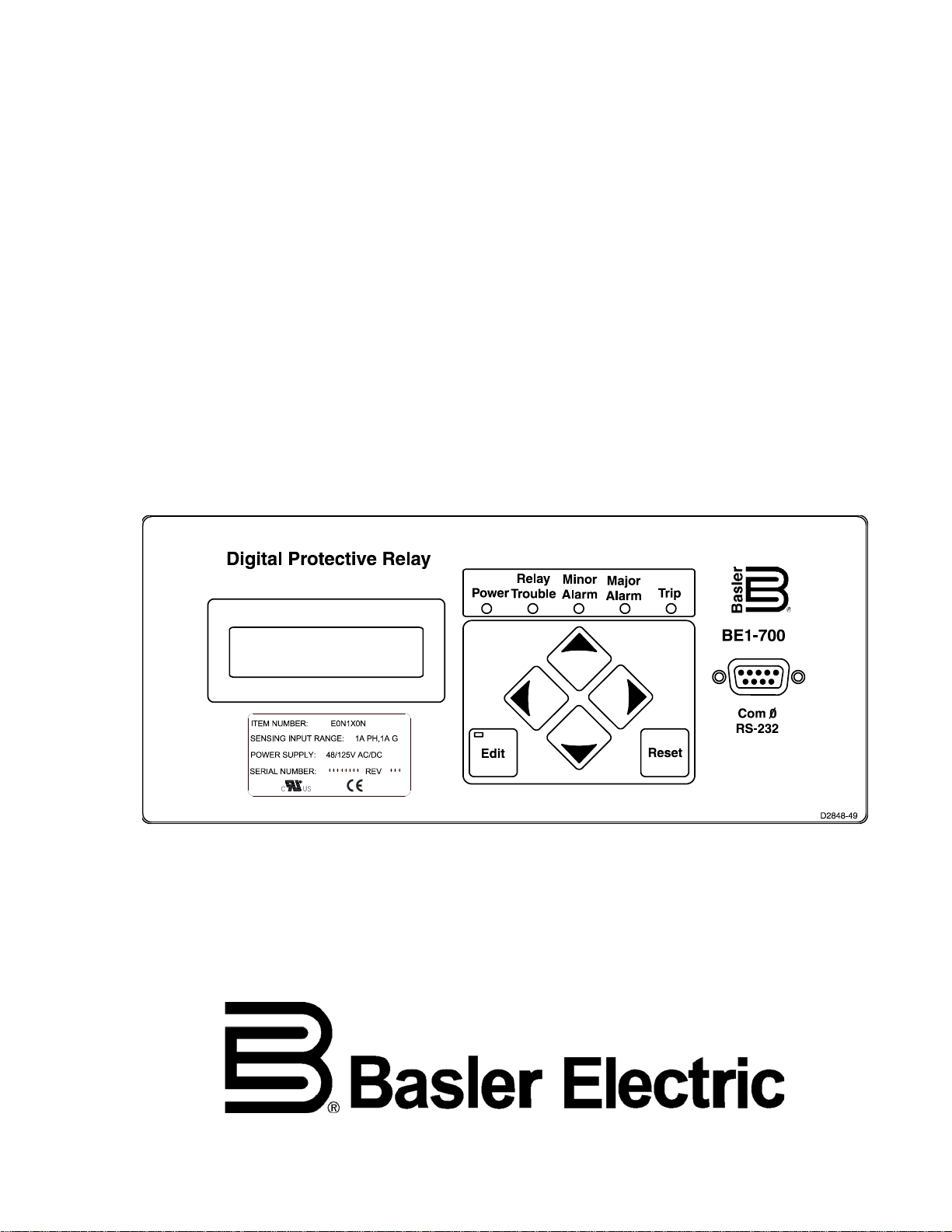
Each BE1-700 comes wi th a front panel display with f ive LED indicators for Pow er Supply Status, Relay
Trouble Alarm, Minor Alarm, Major Alarm, and Trip. The l ighted, liquid crystal display (LCD) allows the
1-4 BE1-700 General Information 9376700990 Rev M
Page 17

relay to replace loca l indication and control functions such as panel metering, alarm annunc iation and
control switches. Four s crolling pushbuttons on the front pan el provide a means to navigate thr ough the
menu tree. Edit and reset pus hbuttons provide access t o change parameters and reset targets , alarms,
and other registers. I n Edit mode, the scrolling pushb uttons provide data entry s elections. Edit mode is
indicated by an Edit LED on the Edit pushbutton.
The LCD has automat ic priority logic to govern what is being displayed on the scr een so that when an
operator approaches, the information of most interest is automatically displayed without having to
navigate the menu structure. The order of priorities is:
1. Recloser Active
2. Targets
3. Alarms
4. Programmable Automatic Scrolling List
Up to 16 screens can be defined in the programmable, automatic scroll list.
Communication
Three independent, isol ated communicatio n ports provide acces s to all functions in the r elay. COM0 is a
nine pin RS-232 port loc ated on the front of the cas e. COM2 is a two wire RS-485 port located on th e
back of the case. The optional rear Ethernet port is referred as Com1 in the BESTCOMS™ General
Operation screen, Security tab.
An ASCII command interface allows easy interaction with the relay using standard, off the shelf
communication software. The ASCII command interface is optimized to allow automation of the relay
setting process. Sett ings f iles c an be capt ured fr om th e relay and ed ited us ing a ny s oftware th at su pports
the ∗.txt file format. These ASCII text files can then be used to set the relay using the send text file
function of your communication software.
A Modbus™ protocol manual (9376700991) is optionally available for the RS-485 communication port.
Ethernet information can be found in Secti on 15, BESTnet™ Communication.
MODEL AND STYLE NUMBER DESCRIPTION
General
The BE1-700 relay electrical characteristics and operational features are defined by a combination of
letters and numbers that mak e up the style number. The model n umber, together with the sty le number,
describes the options included in a specific dev ice and appears on labels o n the front panel and i nside
the case. Upon receipt of a relay, be sure to check the style number against the requisition and the
packing list to ensure that they agree.
The style number id entification chart, Figures 1-1, defines the electrica l characteristics and operational
features included in BE1-700 c urrent and v oltage rela ys. In this manua l, the curr ent relay wil l be referred
to as a BE1-700C and the voltage relay as a BE1-700V.
Sample Style Number
If, for example, the style number were E0N1X0N, the device would be a current relay and have the
following characteristics and features:
BE1-700 —
(E) - 5 ampere phase and independent ground input
(0) - No voltage sensing input
(N) - No reclosing function option
(1) - 48 Vdc power supply
(X) - Pan el mou nt, non-drawout case
(0) - ASCII over RS-485, no Ethernet
(N) - No Option 2 is available
9376700990 Rev M BE1-700 General Information 1-5
Page 18
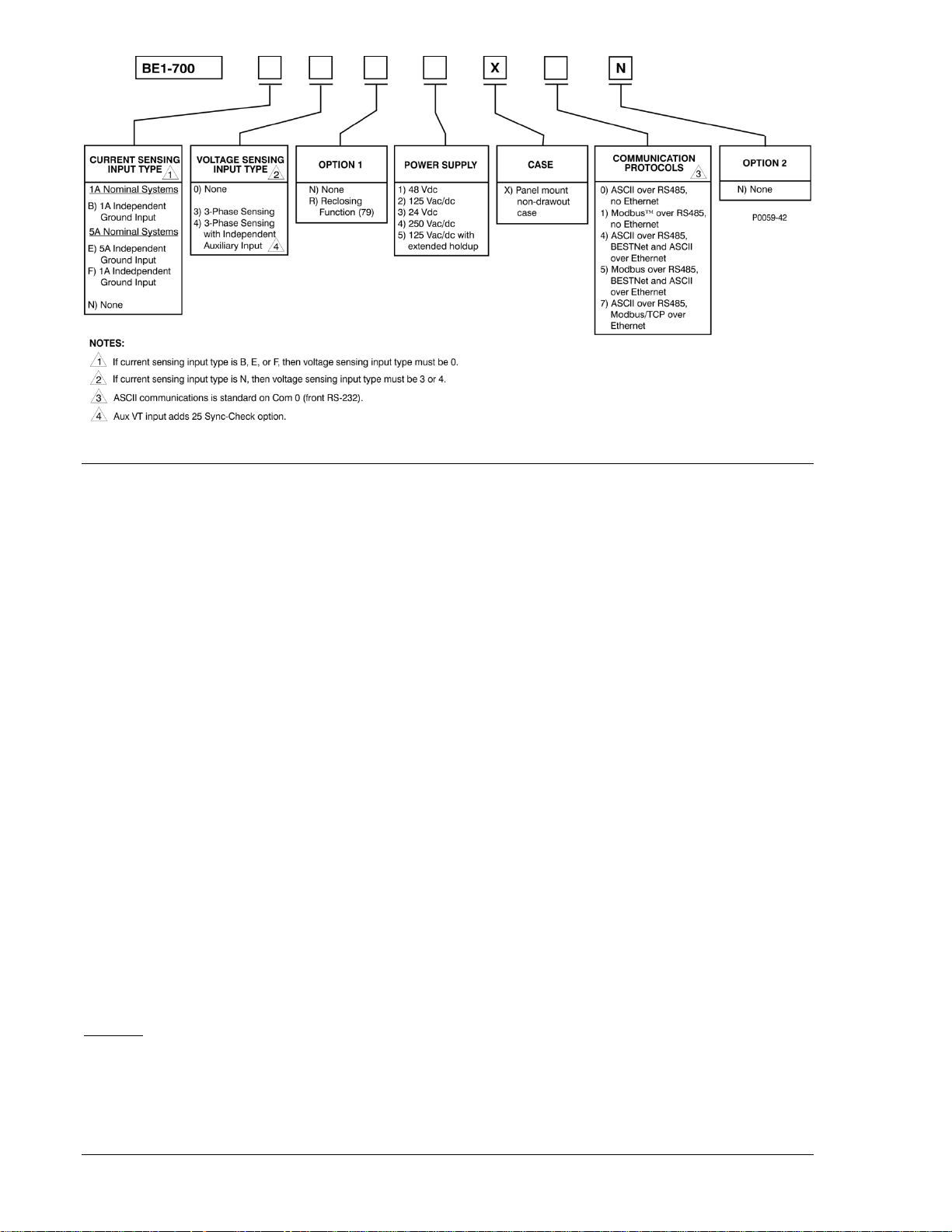
Figure 1-1. Style Number Identification Chart
OPERATIONAL SPECIFICATIONS
Depending on the style ordered, BE1-700 relays have the following features and capabilities:
Metered Current Values and Accuracy (BE1-700C)
Current Range
5 Aac Nominal: 0.5 to 15 Aac
1 Aac Nominal: 0.1 to 3.0 Aac
Accuracy: ±1% of reading, ±1 least si g nif icant dig it at 25°C
Temperature Dependence: ≤ ±0.02% per °C
Metered Voltage Values and Accuracy (BE1-700V)
Voltage Range
3-wire: 0 to 300 V
4-wire: 0 to 300 V
Accuracy (10 to 75 hertz)
50 V to 300 V: ±0.5% of reading, ±1 least significant digit at 25°C
Temperature Dependence: ≤ ±0.02% per °C
Metered Frequency Values and Accuracy (BE1-700V)
Frequency Range: 10 to 75 Hz
Accuracy: ±0.01 hertz, ±1 least significant digit at 25°C
Sensing Input
3-wire: Phase A – B
4-wire: Phase A – Neutral
Minimum Frequency Tracking Voltage: 10 V rms
L-L
L-L
Calculated Values and Accuracy
Demand
Range: 0.1 to 1.5 nominal
Type: Exponential
Accuracy: ±1% of reading ±1 digit at 25°C
Temperature Dependence: ≤ ±0.02% per °C
Interval: 1 to 60 min
1-6 BE1-700 General Information 9376700990 Rev M
Page 19

24 Overexcitation Protection (BE1-700V)
n
NOMINAL
MEASURED
T
1
HZ
V
HZ
V
DT
T
−
=
100*
FST
E
*DT
T
RR
=
Pickup
Setting Range: 0.5 to 6 V/Hz
Accuracy: ±2%
Integrating Time Delay
Time Dial: 0.0 to 9.9
Reset Dial: 0.0 to 9.9
Accuracy: 5% or 4 cycles, whichever is greater
Time to Trip
Time to Reset
where:
T
T
D
D
E
= Time to trip
T
= Time to reset
R
= Time dial trip
T
= Time dial, reset
R
= Elapsed time
T
n = Curve exponent (0.5, 1, 2)
FST = Full scale trip time (TT)
ET/FST = Fraction of total travel toward trip that integration had progressed to. (After a trip,
this value will be equal to one.)
Definite Time Delay
Time Delay: 0.050 to 600 s
Accuracy: 5% or 4 cycles, whichever is greater
25 Sync-Check Protection (BE1-700V, Optional)
Settings
Delta Phase Angle: 1 to 99°
Accuracy: ±0.5°
Delta Voltage Magnitude: 1 to 20 V
Accuracy: ±2% or ±1 V, whichever is greater
Delta Frequency: 0.01 to 0.50 Hz
Accuracy: ±0.01 Hz
Voltage Monitoring
Live/Dead voltage threshold: 10 to 150 V
Accuracy: ±2% or ±1 V
Dropout Time delay: 0.050 to 60 s
Accuracy: ±0.5% or ±2 cycles, whichever is greater
Logic: Dead Phase/Dead Aux
Dead Phase/ Live Aux
Live Phase/ Dead Aux
One independent output: 25VM1
9376700990 Rev M BE1-700 General Information 1-7
Page 20

27P Phase Undervoltage Protection (BE1-700V)
Pickup
Setting Range: 10 to 300 V
Accuracy: ±2% of setting or ±1 V, whichever is greater
Dropout/Pickup Ratio: 102%
Time Delay
Setting Range: 0.05 to 600 s
Accuracy: ±0.5% or ±2.5 cycles, whichever is greater
27X Auxiliary Undervoltage Protection (BE1-700V)
Pickup
Setting Range: 1 to 150 V
Accuracy: ±2% of setting or ±1 V, whichever is greater
Dropout/Pickup Ratio: 102%
Time Delay
Setting Range: 0.05 to 600 s
Accuracy: ±0.5% or ±2.5 cycles, whichever is greater
47 Negative-Sequence Overvoltage Protection (BE1-700)
Pickup
Setting Range: 1.0 to 300 V
L-N
Accuracy: ±2% of setting or ±1 V, whichever is greater
Dropout/Pickup Ratio: 98%
Time Delay
Setting Range: 0.050 to 600 s
Accuracy: ±0.5% or ±2.5 cycles, whichever is greater
50T Instantaneous Overcurrent Prote ction (BE1-700C)
Pickup
Setting Range
5 Ampere CT: 0.5 to 150 A
1 Ampere CT: 0.1 to 30 A
Accuracy (50TP, 50TN)
5 Ampere CT: ±2% or ±50 mA, whichever is greater
1 Ampere CT: ±2% or ±10 mA, whichever is greater
Accuracy (50TQ)
5 Ampere CT: ±3% or ±75 mA, whichever is greater
1 Ampere CT: ±3% or ±15 mA, whichever is greater
Dropout/Pickup Ratio: 95%
Time Delay
Setting Range: 0 to 60 s
Accuracy
50TP, 50TN: ±0.5% or ±½ cycle, whichever is gr eater, plus trip
time for instantaneous response (0.0 setting) *
50TQ: ±0.5% or ±1 cycle, whic hever is greater, plus trip
time for instantaneous response (0.0 setting) *
1-8 BE1-700 General Information 9376700990 Rev M
Page 21

∗ Trip Time for 0.0 Delay Setting
50TP, 50TN: 2¼ cycles maximum for currents ≥ 5 times the
pickup setting. Three cycles maximum for a
current of 1.5 times p ickup. Four c ycles maximu m
for a current of 1.05 times the pickup setting.
50TQ: 3¼ cycles maximum for currents 5 times the
pickup setting. Four cycles maximum for a current
of 1.5 times pickup. Five cycles maximum for a
current of 1.05 times the pickup setting
50BF Breaker Failure Protection (BE1-700C)
Pickup
Setting Range: Fixed at 0.5 A for 5 A unit, 0.1 A for 1 A unit
Accuracy: ±10%
Time Delay
Setting Range: 50 to 999 ms
Accuracy: ±0.5% or +1¼, –½ cycles, whichever is greater
Reset Time: Within 1¼ cycles of the current being removed
51 Time Overcurrent Protection (BE1-700C)
Pickup
Setting Range
5 Ampere CT: 0.5 to 16 A
1 Ampere CT: 0.1 to 3.2 A
Accuracy (51P, 51N)
5 Ampere CT: ±2% or ±50 mA, whichever is greater
1 Ampere CT: ±2% or ±10 mA, whichever is greater
Accuracy (51Q)
5 Ampere CT: ±3% or ±75 mA, whichever is greater
1 Ampere CT: ±3% or ±15 mA, whichever is greater
Dropout/Pickup Ratio: 95%
Time Current Characteristic Curves
Timing Accuracy (All 51 Functions): Within ±5% or ±1½ cycles, whichever is greater,
for time dial settings greater than 0.1 and
multiples of 2 to 40 times the pickup setting but
not over 150 A for 5 A CT units or 30 A for 1 A CT
units.
See Appendix A, Time Overcurrent Character istic
Curves, for information on available timing curves.
59P Phase Overvoltage Protection (BE1-700V)
Pickup
Setting Range: 10 to 300 V
Accuracy: ±2% of setting or ±1 V, whichever is greater
Dropout/Pickup Ratio: 98%
Time Delay
Setting Range: 0.050 to 600 s
Accuracy: ±0.5% or ±2.5 cycles, whichever is greater
9376700990 Rev M BE1-700 General Information 1-9
Page 22

59X Auxiliary Overvoltage Protection (BE1-700V)
Pickup
Setting Range: 1 to 150 V
Accuracy: ±2% of setting or ±1 V, whichever is greater
Dropout/Pickup Ratio: 98%
Time Delay
Setting Range: 0.050 to 600 s
Accuracy: ±0.5% or ±2.5 cycles, whichever is greater
60FL Fuse Loss (BE1-700V)
Time Delay: Fixed at 50 ms
62 Logic Timers
Modes: Pickup/Dropout, 1 Shot Nonretriggerable, 1 Shot
Retriggerable, Oscillator, Integrating, Latch
Setting Range: 0 to 9,999 s
Accuracy: ±0.5% or ±12 ms, whichever is greater
79 Recloser Protection
Reclose (791, 792, 793, 794), Reset (79R), Max Cycle (79M), Reclose Fail (79F), Pilot (79P)
Setting Range: 100 ms to 600 s
Accuracy: ±0.5% or +1¾, –0 cycles, whichever is greater
81 Over/Under Frequency Protection (BE1-700V)
Pickup
Setting Range: 20 to 70 Hz
Accuracy: ±0.01 Hz
Dropout : 0.02 Hz ±0.01 Hz of the actual pickup value
Time Delay
Setting Range: 0.00 to 600 s
Accuracy: ±0.5% or ±1 cycle, whichever is greater, plus 3
cycle recognition time
Voltage Inhibit
Setting Range: 15 to 300 V
Accuracy: ±2% or ±1 V, whichever is greater
Automatic Setting Group Character istics
Number of Setting Groups: 2
Control Modes
Automatic: Cold-Load Pickup, Dynamic Load or Unbalance,
Recloser Shot, or Unbalance (BE1-700C); Fuse
Loss (60FL) (BE1-700V)
External: Discrete Input Logic, Binary Input Logic
Switch Level
Setting Range: 0 to 150% of the Setting Group 0, monitored
element setting
Accuracy: ±2% or ±50 mA (5 A), ±2% or ±10 mA (1 A)
Switch Timer
Setting Range: 0 to 60 min with 1 min increments where 0 =
disabled
Accuracy: ±0.5% or ±2 s, whichever is greater
1-10 BE1-700 General Information 9376700990 Rev M
Page 23

BESTlogic™
Update Rate: ½ cycle
GENERAL SPECIFICATIONS
AC Current Inputs (BE1-700C)
5 Ampere CT
Continuous Rating: 20 A
One Second Rating: 400 A
For other current levels, use the formula: I= (K/t)
Begins to Clip (Saturate): 150 A
Burden: <0.01 Ω
1 Ampere CT
Continuous Rating: 4 A
One Second Rating: 80 A
For other current levels, us e the follow ing formu la: I = ( K/t)
mount, non-drawout case).
Begins to Clip (Saturate): 30 A
Burden: ≤0.01 Ω at 1 A
Phase AC Voltage Inputs (BE1-700V)
Continuous Rating: 300 V, Line to Line
One Second Rating: 600 V, Line to Line (3-wire sensing)
600 V, Line to Neutral (4-wire sensing)
Burden: <1 VA at 300 Vac
½
where t = time in seconds, K = 160,000.
½
where t = time in seconds, K = 9 0,000 (pane l
Auxiliary AC Voltage Inputs
Continuous Rating: 150 V, Line to Line
Fault Rating: 360 V, Line to Line
One Second Rating: 600 V, Line to Neutral
Burden: <1 VA at 150 Vac
Analog to Digital Converter
Type: 16-bit
Sampling Rate: 12 samples per cyc le, adjusted to input frequency
(10 to 75 Hz)
Power Supply
Power supply ranges and holdup times are listed in Table 1-1.
Table 1-1. Power Supply Ranges and Holdup Times
Style Option AC Range AC Holdup Time DC Range DC Holdup Time
1) 48 Vdc N/A N/A 35 to 150 Vdc 30 ms
2) 125 Vac/dc 90 to 270 Vac 70 ms 90 to 300 Vdc 50 ms
3) 24 Vdc N/A N/A 17 to 32 Vdc † 80 ms
4) 250 Vac/dc 90 to 270 Vac 280 ms 90 to 300 Vdc 170 ms
5) 125 Vac/dc *
55 to 135 Vac 280 ms 35 to 150 Vdc 170 ms
* Extended holdup option. See Style Chart in Figure 1-1.
† Operates down to 8 Vdc momentar ily.
9376700990 Rev M BE1-700 General Information 1-11
Page 24

Frequency Range
Options 1, 2, and 4 only: 40 to 70 Hz
Burden
Options 1, 2, 3, 4, 5: 8 W continuous, 11 W maximum w ith all outputs
energized
Output Contacts
Make and Carry for Tripping Duty: 30 A for 0.2 seconds per IEEE C37.90;
7 A continuous
Break Resistive or Inductive: 0.3 A at 125 or 250 Vdc (L/R = 0.04 maximum)
Contact-Sensing Inputs
Contact-sensing turn-on voltages and burdens are listed in Table 1-2. Burden values assume nominal
value of input voltage applied.
Table 1-2. Contact-Sensing Turn-On Voltages and Burdens
Style Option Nominal Input Voltage
xxx1xxx 48 Vdc 26 to 38 Vdc 23 kΩ
xxx2xxx 125 Vac/dc
xxx3xxx 24 Vdc Approx. 5 Vdc 6 kΩ
xxx4xxx 250 Vac/dc
xxx5xxx
* AC voltage ranges are calculated using the default recognition time (4 ms) and debounce time (16 ms).
† Extended holdup option. See Style Chart in Figure 1-1.
Recognition Time
Programmable ................................................................ 4 to 255 ms
All timing specifications are for the worst-case response. This includes output
contact operate times and standard BESTlogic operation timing but excludes
input debounce timing and non-standard logic configurations. If a non-standard
logic scheme involves feed back, then on e or more BESTlogic update rate d elays
must be included to calcul ate the worst-case delay. An example of feedbac k is
Virtual Outputs drivin g Function Block Inputs. For more informatio n, see Section
7, BESTlogic Programmable Logic.
125 Vac/dc †
Contact-Sensing Turn-On Voltage *
69 to 100 Vdc
56 to 97 Vac
138 to 200 Vdc
112 to 194 Vac
69 to 100 Vdc
56 to 97 Vac
NOTE
Burden
53 kΩ
123 kΩ
53 kΩ
IRIG
Supports IRIG Standard 200-98, Format B002
Input Signal: Demodulated (dc level-shifted digital signal)
Logic-High Voltage: 3.5 Vdc, minimum
Logic-Low Voltage: 0.5 Vdc, maximum
Input Voltage Range: ±20 Vdc, maximum
Resistance: Nonlinear, approximately 4 kΩ at 3.5 Vdc,
approximately 3 kΩ at 20 V dc
1-12 BE1-700 General Information 9376700990 Rev M
Page 25

Real-Time Clock
Accuracy: 1 second per day at 25°C (free running) or
±2 milliseconds (with IRIG synchronization)
Resolution: 1 millisecond
Date and Time Setting Provisions: Front panel, communications port, and IRIG. Leap
year and selectable daylight saving time
correction provided.
Communication Ports
Interface
Front RS-232: 300 to 19200 baud, 8N1 full duplex
Rear RS-485: 300 to 19200 baud, 8N1 half duplex
Rear Ethernet: IEEE 802.3 (10BaseT)
Response Time (RS-232): <100 ms for metering and control functions
Display
Type: Two line, 16 character alphanumeric LCD (liquid
crystal display) with LED (light emitting diode);
backlight
Operating Temperature: –40°C (–40°F) to +70°C (+158°F).
Display contrast may be impaired at temperatures
below –20°C (–4°F).
Isolation
Meets IEC 255-5 and exceeds IEEE C37.90 one minute dielectric test as follows:
All Circuits to Ground*: 2,000 Vac or 2,828 Vdc
Input Circuits to Output Circuits: 2,000 Vac or 2,828 Vdc
Communication Ports to Ground†: 700 Vdc for one minute
* Excludes communication ports.
† Ethernet port excluded from dielectric tests.
Surge Withstand Capability
Oscillatory
IEEE Std C37.90.1-2002 - IEEE Standard Surge Withs tand Capa bility (S WC) Test s for Relays and R elay
Systems Associated with Electric Power Apparatus (Excludes front panel RS-232 communication port.
Shielded RJ-45 cable is required for the Ethernet port.)
Fast Transient
Qualified to IEEE Std C37.90.1-2002 - IEEE Standard Surge Withstand Capability (SWC) Tests for
Relays and Relay Systems Associated with Electric Power Apparatus. (Due to surge suppression
components, excludes application across open output contacts. Excludes front panel RS-232
communication port. Shielded RJ-45 cable is required for the Ethernet port.)
Radio Frequency Interference (RFI)
Qualified to IEEE Std C37.90.2-2004 - IE EE Sta ndar d Withstand Capability of Relay Systems to R adi ate d
Electromagnetic Interference from Transceivers.
Electrostatic Discharge (ESD)
IEEE Std C37.90.3-2001 - IEEE Standa rd Electrostatic Discharge Test for Protective Relays.
Shock
Qualification: IEC 255-21-2, Class 1
9376700990 Rev M BE1-700 General Information 1-13
Page 26

Vibration
Qualification: IEC 255-21-1, Class 1
Environment
Temperature
Operating Range: –40°C to 70°C (–40°F to 158°F) *
Storage Range: –40°C to 70°C (–40°F to 158°F)
∗ Display is inoperative below –20°C
Humidity
Qualified to IEC 68-2-38, 1st Edition 1974, Basic Environmental Test Procedures, Part 2: Test Z/AD:
Composite Temperature Humidity Cyclic Test.
CE Compliance
This product meets or exceeds the standards required for distribution in the European Community.
UL Recognition for US and Canada
UL recognized per Standard 508 and Standard CAN/CSA-C22.2 Number 14-M91, UL File Number
E97033. Note: Output contacts are not recognized for voltages greater than 250 V.
GOST-R Certification
GOST-R certified per the relevant standards of Gosstandart of Russia.
Physical
Weight: 4.33 lb (1.96 kg) maximum
Case Size: See Section 12, Installation.
1-14 BE1-700 General Information 9376700990 Rev M
Page 27

SECTION 2 • QUICK START
TABLE OF CONTENTS
SECTION 2 • QUICK START .................................................................................................................... 2-1
GENERAL .............................................................................................................................................. 2-1
About This Manual ............................................................................................................................. 2-1
BESTlogic .............................................................................................................................................. 2-2
Characteristics of Protection and Control Function Blocks ................................................................ 2-2
Function Block Logic Settings ............................................................................................................ 2-2
Output Logic Settings ......................................................................................................................... 2-3
USER INTERFACES ............................................................................................................................. 2-3
Front Panel HMI ................................................................................................................................. 2-3
ASCII Command Communications .................................................................................................... 2-4
BESTCOMS™ for BE 1 -700, Graphical User Interface ....................................................................... 2-5
GETTING STARTED ............................................................................................................................. 2-6
Entering Test Settings ........................................................................................................................ 2-6
Checking the State of Inputs .............................................................................................................. 2-6
Testing ................................................................................................................................................ 2-7
FAQ/TROUBLESHOOTING .................................................................................................................. 2-7
Frequently Asked Questions (FAQs) ................................................................................................. 2-7
Figures
Figure 2-1. 51 Time Overcurrent Logic (BE1-700C) ................................................................................. 2-2
Figure 2-2. Menu Screens Numbering Example ....................................................................................... 2-4
Tables
Table 2-1. Function Categories and Manual Sections Cross-Reference .................................................. 2-1
Table 2-2. Trip LED Truth Table ................................................................................................................ 2-9
9376700990 Rev M BE1-700 Quick Start i
Page 28

This page intentionally left blank .
ii BE1-700 Quick Start 9376700990 Rev M
Page 29

SECTION 2 • QUICK START
Section Title
Section
GENERAL
This section provides an overview of the BE1-700 Digital Protective Relay. You should be familiar with the
concepts behind the user inter faces and B ESTlo gic before y ou begin read ing ab out t he det ailed BE1-700
functions. Sections 3 through 6 in the instruction manual describe each function of the BE1-700 in detail.
The following information is intended to provide the reader with a basic understanding of the user
interfaces and the sec urity features pr ovided in the BE1-70 0 relay. Detailed information on th e operation
of the human-machin e interface (HMI) can be found i n Section 10, Human-Machine Inter face, and the
ASCII command commun ic atio ns in Sec t ion 11, ASCII Command Interface. BE ST COMS™ is a Wind ows
based software appl ication that enhances comm unication between the PC user and the BE1-700 re lay.
BESTCOMS for th e BE1-700 is prov ided free of char ge with the B E1-700. BESTCO MS operation is v ery
transparent, and does contain a Windows type help file for additional operational details.
Also covered in this section is an overview of BESTlogic, which is fundamental to how each of the
protection and control functions is set-up and used in the BE1-700 relay. Detailed i nformation on using
BESTlogic to design comp lete protection and control schemes for the prot ected circuit can be found in
Section 7, BESTlogic Programmable Logic, and Section 8, Application.
Sections 3 through 6 desc ribe each func tion provided in th e BE1-700 rel ay and include r eferences to the
following items. Note that not all items are appropriate for each function.
• Human-machine interface (HMI) screens for setting the operational parameters.
• BESTCOMS for setting the operational parameters.
• BESTCOMS for setting up the BESTlogic required for functions in your protection and control
scheme.
• Outputs from the function such as alarm and BESTlogic variables or data reports.
• HMI screens for operation or interrogation of the outputs and reports provided by each function.
• ASCII commands for operation or interrogation of the outputs and reports provided by each
function.
®
About This Manual
The various application functions provided by this multifunction relay are divided into four categories:
input/output functions, protection and control functions, metering functions, and reporting and alarm
functions. Detailed des criptions of each ind ividual func tion, s etup, and us e are cov ered in the sec tions as
shown in Table 2-1. Detailed informa tion on using progr ammable logic to create your own pr otection and
control scheme is described in Section 7, BESTlogic Programmable Logic. Section 15, BESTNet
Communication, provides information on all of the device Ethernet features and capabilities. Browser
screen shots of available web pages are illustrated and explained.
Table 2-1. Function Categories and Manual Sections Cross-Reference
Input and Output Functions Section 3
Protection and Control Section 4
Metering Section 5
Reporting and Alarm Functions Section 6
BESTlogic Programmabl e Log ic Section 7
Application Section 8
BESTNet Communication Section 15
9376700990 Rev M BE1-700 Quick Start 2-1
Page 30
BESTLOGIC
Each of the protection an d control functions in the BE1-70 0 is implemented as an independent f unction
block that is equivale nt to a s ingle functio n, discr ete dev ice counterpar t. Each independ ent function block
has all of the inputs and outputs that the discrete component counterpart might have. Programming
BESTlogic is equivalent to choosing the devices required by your protection and control scheme and
drawing schematic diagrams to connect the inputs and outputs to obtain the desired operational logic.
The concept is the sam e but the met hod is d ifferent i n that yo u choose eac h func tion block by enabling it
and use Boolean logic expr essions to c onnect the inputs and outputs. Th e result i s that in des igning your
system, you have even gr eater flexibility than you had using discrete dev ices. An added benefit is that
you are not constrained by the flexibility limitations inherent in many multifunction relays.
One user programmab le, custom logic scheme created by the user may be programmed and saved in
memory. To save you time, s everal preprogrammed logic schemes have also been pr ovided. Any of the
preprogrammed sche mes can be cop ied into the pr ogrammable log ic settings w ithout the user having to
make any BESTlogic programming.
There are two types of B ESTlogic settings: func tion block logic s ettings and output log ic settings. These
are described briefly in the following paragraphs. Detailed information on using BESTlogic to design
complete protection and co ntrol schemes for the protected circ uit can be found in Section 7, BESTlogic
Programmable Logic, and Section 8, Application.
Characteristics of Protection and Control Function Blocks
As stated before, each function block is equivalent to a discrete device counterpart. For example, the
phase time-overcurr ent function block in the BE1-700 r elay has all of the characteristics of Bas ler BE1
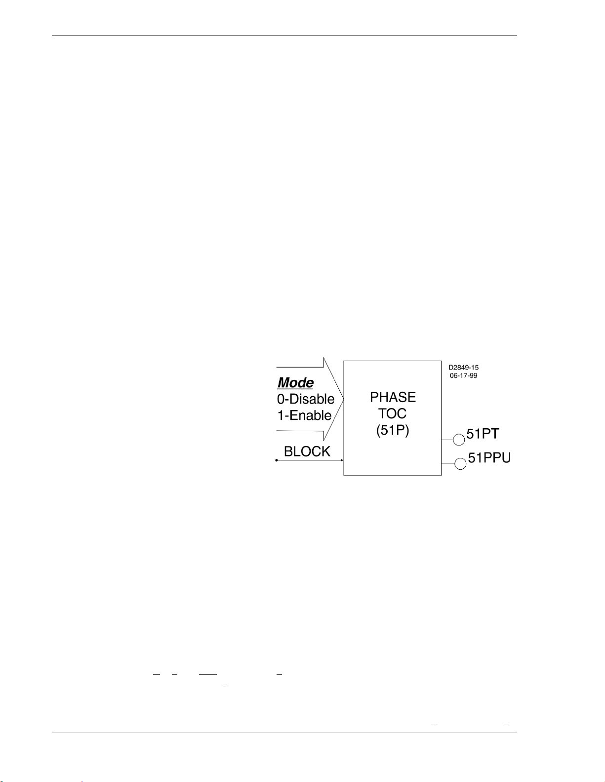
relays with similar functionality. Figure 2-1 is a logic drawing showing the inputs and outputs.
One input:
• BLK (block 51P operation)
Two mode settings:
• Enable 51P operation
• Disable 51P operation
Two outputs:
• 51PT (51 Phase Trip)
• 51PPU (51 Phase Pickup)
Four operational settings:
• Pickup
• Time Delay
• Characteristic Curve
Of the above characteristic s, the four operational setti ngs are not included in the logic sett ings. They are
contained in the protection settings. This is an important distinction. Since changing logic settings is
similar to rewiring a pa nel, the logic s ettings are separ ate and distinct from t he operationa l settings such
as pickups and time delays.
Function Block Logic Settings
To use a protection or control function block, there ar e two items that need t o be set: Mode and Input
Logic. The mod e is equivalent t o deciding wh ich devic es you want to insta ll in your protec tion and contr ol
scheme. You then must set the logic variables that will be connected to the inputs.
For example, the 51N function block has three modes (disabled, three-phase summation (3Io), and
ground), and one input, block (torque control). To use this function block, the logic setting command might
be SL-51N=1,/IN2 for Set Logic-51N to be Mode 1 (three-phase and n eutral) with the funct ion blocked
when Contact Sensing Inp ut 2 is not (/) energized. Contact Sensing Inpu t 2 would be wired to a ground
relay enable switch.
As noted before, the pr otection settings for this funct ion block, pickup, time dia l, and curve must be set
separately in the settin g gr oup sett ings. T he sett ing m ight be S0-51N =6.5, 2.1,S1 R for Set ting in gr oup 0 -
Figure 2-1. 51 Time Overcurrent Logic (BE1-700C)
2-2 BE1-700 Quick Start 9376700990 Rev M
Page 31

the 51N function = pickup at 6.5 amps with a time dial of 2.1 using curve S1 with an integrating Reset
characteristic.
The 51N function block has two logic output variables, 51NT (Trip) and 51NPU (Picked Up). The
combination of the logic settings and the operational settings for the function block govern how these
variables respond to logic and current inputs.
Output Logic Settings
BESTlogic, as implemented in the BE1-700, supports up to 16 output expressions. The output
expressions are called virt ual outputs to distinguis h them from the physical out put relays. VOA and VO1
through VO5 drive phys ical outputs O UTA (failsafe a larm output) a nd OUT1 throu gh OUT5, respectively.
The rest of the virtual outputs can be used for intermediate logic expressions.
For example, OUT 1 is wir ed to the trip bus of th e circuit breaker . To set up the logic to trip the breaker,
the BESTlogic setting com mand might be SL-VO1=VO11+101T+BFPU for Set Logic - Virtual Output 1 =
to Virtual Output 11 (which is the intermediate logic expression for all of the function block tripping
outputs) or (+) 101T ( th e tr i p outp ut of t he v irtu al br eaker control switch) or ( +) BFPU (the pickup o utput of
the breaker failure function block that indicates that breaker failure has been initiated).
USER INTERFACES
Three user interfaces are provided for interacting with the BE1-700 relay: front panel HMI, ASCII
communications, and BESTC OMS for BE1-700. The fr ont panel HMI provides access to a subset of t he
total functionality of the de vice. ASCII communications provides access to all settings, controls, r eports,
and metering functions of the system. BESTCOMS for BE1-700 is software used to quickly develop
setting files, view metering data, and download reports in a user-friendly, Windows based enviro nme nt.
Front Panel HMI
The front panel HMI consis ts of a two line by 16 character LCD (liq uid crystal display) with four sc rolling
pushbuttons, an edit pushbutton, and a reset pushbutton. The EDIT pushbutton includes an LED to
indicate when edit mo de is active. There are five other LEDs for indicating power supply status, relay
trouble alarm status, programmable major and minor alarm status, and a multipurpose Trip LED that
flashes to indicate th at a protective element is pic ked up. The Trip LED lights continuously when the trip
output is energized a nd seals in when a protective tr ip has occurred to indicate that target informati on is
being displayed on the LCD. A complete description of the HMI is included in Section 10, Human-Machine
Interface.
The BE1-700 HMI is m enu dr iven and organized into a men u tr e e s truc tur e w ith s i x br anc hes. A com pl ete
menu tree description with display s is als o prov ided in Section 10, Human-Machine Inter face. A lis t of t he
menu branches and a brief description for scrolling through the menu is in the following paragraphs.
1. REPORT STATUS. Display and resetting of g eneral status information suc h as targets, alarms,
recloser status.
2. CONTROL. Operation of manual controls such as virtual switches, selection of active setting
group, etc.
3. METERING. Display of real-time metering values.
4. REPORTS. Display and re setting of report informatio n such as time an d date, deman d registers ,
breaker duty statistics, etc.
5. PROTECTION. Display and setting of protective function setting parameters such as logic
scheme, pickups, time delays, etc.
6. GENERAL SETTING S. D isplay and set ting of non-protective function setting parameters such as
communication, LCD contrast, and CT ratios.
Each screen is assigned a numb er in the HMI section. The number indicates the branch and leve l in the
menu tree structure. Sc reen numbering helps you to keep track of w here you are when you leave the
menu tree top level. You view each branch of the menu tree by using the RIGHT and LEFT scrolling
pushbuttons. To go to a level of greater detail, you use the DOWN scrolling pushbutton. Each time a
lower level in a menu branch is reached, the screen number changes to reflect the lower level. The
following paragraphs and Figure 2-2 illustrate how the display screens are numbered in the menu tree.
Viewing the 47 pickup and time delay settings of Setting Group 1 involves the following steps:
9376700990 Rev M BE1-700 Quick Start 2-3
Page 32

1. At the top level of the menu tree, use the LEFT or RIGHT scrolling pushbuttons to get to the
PROTECTION logic branch (Screen 5).
2. Press the DOWN scrolling pushbutton to reach the SETTING GROUP level (Screen 5.1).
3. Scroll RIGHT to SETTING GROUP 1 branch (Screen 5.2).
4. From Screen 5.2, scroll down to the next level of detail which is the 24 SETTINGS (Screen 5.2.1).
5. Scroll right to the 47 SETTINGS ( Screen 5.2.5) and then do wn to reach the 47 pickup an d time
delay settings (Screen 5.2.5.1).
Figure 2-2. Menu Screens Numbering Example
ASCII Command Communications
The BE1-700 relay has two independent communications ports for serial communications plus one
optional rear Ethernet port. A computer terminal or PC running a terminal emulation program such as
Windows HyperTerminal can be connected to any of the ports so that commands can be sent to the relay.
Communication with the rel ay uses a s imple ASCII comma nd language . When a c ommand is enter ed via
a serial port, the relay resp onds with the appr opriate ac tion. ASCII command c ommunicati on is designed
for both human-to-machi ne interactions and batch download type operations. The following paragraphs
briefly describe the c ommand structur e and discuss h uman-to-machine interacti ons and batch command
text file operations. The operation of the ASCII commands is described in detail in Section 11, ASCII
Command Interface.
Command Structure
An ASCII command cons ists of a command string made up of one or tw o letters followed by a hyphen
and an object na me. The fir st letter specif ies the ge ner al comma nd func tion and t he secon d a sub-group.
The object name is the sp ecific function for which th e command is intended. A comma nd string entered
alone is a r ead command . A com mand str ing followed by an equa l sign and o ne or mor e parameter s is a
write command. The general command groups are organized into five major groups plus several
miscellaneous commands. These commands are as follows:
C CONTROL. Commands to perform select be fore operate c ontrol actions such as tripp ing and closing
the circuit breaker, c hanging the activ e setting group, etc. Subgroups incl ude S for Select and O for
Operate.
G GLOBAL. Perfor m global operations th at do not fall in to the other general gr oups such as passwor d
security. Subgroups include: S for security settings.
M METERING. Read all real time metering values. This general command group has no subgroups.
P PROGRAM. Subgroup command to read or program a setting.
R REPORTS. Read and r eset reporting functions such as time an d date, demand registers, breaker
duty statistics, etc. Subgroups include: A for Alarm functions, B f or Breaker monitoring f unctions, D
for Demand recording f unctions, F for Fault summar y reporting f unctions, G f or Genera l information,
and S for sequence of events recorder functions.
2-4 BE1-700 Quick Start 9376700990 Rev M
Page 33

S SETTI NGS. Set all setting parameter s that govern the function ing of the relay. Subgroups include:
0,1, for settings in setting groups, A for alarm settings, B for breaker monitoring settings, G for
general settings, and L for logic settings.
MISCELLANEOUS. Miscellaneous commands include ACCESS, EXIT, and HELP.
Examples of object names would be 51 N for the n eutr al invers e time over current funct ion or PI A for the A
phase, peak current demand register.
For example, to chec k the 51N pickup setting in Sett ing Group 1, you would enter S1-51N for Setting,
Group 1-51N. The relay woul d respond with the current pickup , time dial and curve settings for th e 51N
function. To edit these sett ings the sam e comm and woul d be use d with an = followed by the new s ettings
and the ENTER pushbutton. Note that its necessary to use the ACCESS and EXIT commands when
using the write version of these commands.
ASCII Command Operations
Using ASCII commands, settings can be read and changed on a function-by-function basis. The
mnemonic format of the co mmands hel ps you interac t with the r elay. It isn't nec ess ary to remember a ll of
the object names. Mos t comma nds don't requ ire that y ou specify a co mplete obj ect name. If the first two
letters of a command are entered, the relay will respond with all applicable object names.
Example 1: Obtain a breaker operations count by entering RB (Report Breaker). The BE1-700
responds with the op erations count er value along wit h all other breaker report object s. If
you know that the object n ame for the breaker operat ions counter is OPCNTR, you can
enter RB-OPCNTR and read only the number of breaker operations.
Partial object names are also supported. This allows multiple objects to be read or reset at the same time.
Example 2: Read all peak-since-reset demand registers. Entering RD-PI (report demand - peak
current) will return demand values and time stamps for phase A, B, C, neutral and
negative-sequence curr ent. To read only the neutral demand val ue, the full object nam e
(RD-PIN) is entered. Entering RD-PI=0 resets all five of the peak-since-reset demand
registers.
Batch Command Text File Operations
With a few exceptions, eac h function of th e relay uses one comm and to set it and each settin g command
operates on all of t he para meters req uired by that fun ction. See t he examp le mentio ned previ ously in the
paragraph titled Comma nd Structure. Th is form at res ults in a gr eat ma ny comm ands to fully set the re lay.
Also, the process of setting the relay does not use a prompting mode wher e the relay prompts you f or
each parameter in turn until you ex it the s etti ng proc ess. For these reasons, a method for setting the r elay
using batch text files is recommended.
In batch download type oper ations, the user creates an ASCII text fi le of commands and sends it to the
relay. To facilitate this process, the response from a multiple read command is output from the BE1-700 in
command format. So the u ser need only enter S for Set (with no subgroup) and the relay responds with
all of the setting commands and their associated parameters. If the user enters S1 for Setting Group 1,
the relay responds with all of the setting commands for setting group 1. The user can capture this
response to a file, edit it us ing any A SCII text ed itor, a nd then s end the f ile back to the r elay. See Sec tion
11, ASCII Command I nterf ac e, for a more detailed discus sion of how to use ASCII text files for set t ing the
relay.
BESTCOMS™ for BE1-700, Graphical User Interface
Basler Electric's graphic al user interface (GUI) software is an alternat ive method for quickly developing
setting files in a user -friend ly, Windows based environment. Using t he GUI, you may prep are settin g files
off-line (without being connected to the relay) and then upload the settings to the relay at your
convenience. These settings include protection and control, operating and logic, breaker monitoring,
metering, and fault recor ding. Engineering pers onnel can develop, test, and r eplicate the settin gs before
exporting it to a file and transmitting the file to technical personnel in the field. On the field end, the
technician simply impor ts the f ile into t he BESTCOM S data base and uploads the file to the r elay wher e it
is stored in nonvolatile memory.
The GUI also has the sam e preprogrammed logic schemes that ar e stored in the relay. This gives the
engineer the option (off-line) of developing his setting file using a preprogrammed logic scheme,
customizing a preprogr ammed logic sche me, or building a sch eme from scratch. Fi les may be exported
from the GUI to a text ed itor where they can be revie wed or modifi ed. The modif ied text file may then be
uploaded to the relay. Afte r it is uploaded to the relay, it can be brought into the GU I but it cannot be
9376700990 Rev M BE1-700 Quick Start 2-5
Page 34

brought directly into the GUI from the text file. The GUI logic builder uses basic AND/OR gate logic
combined with point and c lick variables to build th e logic expressions. Th is reduces the design t ime and
increases dependability.
The GUI also allows for downloading industry standard COMTRADE files for analysis of stored
oscillography data. Deta iled analysis of the oscillogra phy files may be accomplished us ing BESTWAVE.
For more information on Bas ler Electric's Windows based BESTCOMS (GUI) s oftware, refer to Section
14, BESTCOMS Software.
GETTING STARTED
If your relay has Power Supply Opti on 2, it can be supplied by norm al 120 Vac house pow er. This power
supply option is the 125 V ac/Vdc power supply. The contact sensing inputs are half-wave rectified optoisolators. The default c onta ct rec ognition and d ebo unce s ettings enabl e their us e on ac s ignals as well as
dc signals.
The BE1-700 measures t he A phas e, B phas e, and C phas e current m agnitu des and angles direc tly f rom
the three current sensing inputs. The neutral, positive, and negative-sequence magnitudes and angles
are calculated from the fun dame nt a l comp one nt of each of the three-ph as e cur rent s. Wh en ev a luat in g the
negative-sequence functions, the relay can be tested using a single-phase current source. To fully
evaluate the operation of the relay in the power system, it is desirable to use a three-phase current
source.
Connect a computer t o the front RS-2 32 port (refer to Sect ion 12, Installation, for connection di agrams).
Apply power and Enter A= to gain setting access. Set the clock using the RG-TIME= and RG-DATE=
commands. (Refer to Section 11, ASCII Command Interface, for addition al inf orm atio n.)
Entering Test Settings
Enter SG (Setting Gener al) to get a listing of the general sett ing commands w ith default parameters and
put them in a tex t file as described previous ly in Batch Command Text F ile Operations. Then enter S0
(setting group 0) to get a lis ting of the group 0 protec tion setting comma nds with default par ameters and
put them in a text file a lso. With these two sub-groups of s ettings, you will not see the global secur ity
settings, user programm able BESTlog ic settings, setti ngs for protection Setting Groups 0 and 1, settings
for alarm functions, and the settings for breaker monitoring functions.
Open the SG file in a text editor, change settings, as required and save the changes. For example:
• The ratios for the phase and neutral current transformers (CTP, CTG).
• The demand inter val and C T circuit to mon itor for the phase, neutral and n egativ e-sequence c urrents
(DIP, DIN, DIQ).
• The nominal system frequency (FREQ).
• The normal phase-sequence (ABC or ACB) for the system (PHROT).
• Open the S0 file in a text editor, change settings as required, and save the changes.
Do not forget to add E;Y (Exit; Save Settings? Yes) to the end of both files. Enter A= to gain setting
access and then send each of thes e text files to the relay as described above under Batch Comman d
Text File Operations.
As you gain knowledge of t he relay, you ca n experime nt with the res t of the sett ings. To s et up a file with
all user settings, enter S and the relay will respond with all settings in command format. For
documentation, the user should use the Print command in BESTCOMS settings.
Default settings can be found several different ways. The default preprogrammed logic scheme is
dependent on the type of relay. (See Style Chart in Section 1, General Information.) Section 8,
Application, lists all of the default logic settings for the default logic scheme. If you wanted to know th e
default logic setting for relay output 3 (VO3), you could look at the default listing and find that SLVO3=51PT. Translate d, this means t hat the settin g, logic – Virtual Outpu t 3 is TRUE (1) when t he phase
time-overcurrent e lement tr ips. You cou ld also look in Secti on 4, Protec tion and Control, f ind the t able for
the logic settings. It lists the same information, but it lists the mode and block inputs separately. If you
want to find the default settings for an input or output, look in Section 3, Input and Output Functions.
Checking the State of Inputs
You can review the state of the inputs throu gh the fron t panel HMI , BE STCOM S meter ing scr eens, or t he
ASCII command interface. The front panel HMI displays the input status on Screen 1.5.1. A diagram
2-6 BE1-700 Quick Start 9376700990 Rev M
Page 35

showing all of the menu tre e branches is located in S ection 10, Human-Mac hine Interface. To g et to this
screen, press the UP scrolling pushbutton un til you reac h the top screen in t he current br anch. You know
when you have reached the top screen because the screen stops changing when you press the UP
scrolling pushbutton. Fr om this posit ion, pr ess the RIGHT scrolling pushbutton unt il you hav e reache d the
screen titled, REPORT STATUS. From this position press the DOWN scrolling pushbutton one time
(TARGETS) and press the RIGHT scrolling pushbutton three times. At this time, you should see the
OPERATIONAL STATUS Screen. If you press the DOWN scrolling pushbutton from this screen, you
should see the INPUTS Screen (IN 1234).
To check the state of th e in puts usi ng the ASCII comm and int erface, type in the RG -STAT comman d and
press enter. This command only reads the status of the inputs.
Testing
To determine if the relay is responding correctly to each test, the following commands are useful:
1. RG-TARG, (report general targets): reports the targets from the last fault.
2. RF, (report faults ): reports a directory l isting of the twelve fault su mmary reports. The fau lt summary
reports are numbered from 1 to 255, then wrap around, and start over. RF-### reports the ### report.
3. RS-##, (report seque nce of events record), ## events: repor ts the most recent ## changes of state
in the protection and control logic.
FAQ/TROUBLESHOOTING
Frequently Asked Questions (FAQs)
1.) Why won't the Trip LED reset when I press the Reset key on the front panel?
The Reset key is contex t sensitive. To reset the Trip LED or the targets , the Targets screen must
be displayed. To reset the alarms, the Alarms screen must be displayed.
2.) Is the power supply polarity sensitive?
No, the power supply will ac cept either an ac or dc voltage input. How ever, the cont act sensing for
the programmable inputs is polarity sensitive. Refer to Section 12, Installation, for typical
interconnection diagrams.
3.) What voltage level is used to develop curre nt flow through the contact sensing inputs?
Voltage level is depend ent on the power supp ly option (called out in th e BE1-700 style char t). For
additional information, see Figure 1-1 in Section 1, General Information, and Section 12,
Installation.
4.) Does the BE1-700 trip output contact latch after a fault?
The answer to the question is yes and no. In genera l, once the fault go es away the outp ut contacts
open. The BE1-700 do es offer an option to ens ure that the contact will stay c losed for at least 200
milliseconds. See Section 3, In put an d Ou tput Func tio ns, for additional informat ion on that funct ion.
But, BESTlogic can ke ep the relay outputs closed as long as power is applied. Refer to Sectio n 8,
Application, Application Tips, for additional information.
5.) Why won't a function work when I put in settings such as the pickup and time delays?
Make sure that the logic for the function is set to "Enable".
6.) How many overcurrent elements does the BE1-700 have available?
The BE1-700 has six i nstantaneous overcurr ent and four time overcurrent elements . Just like any
element each of these elements can be assigned to any output for building logic equations.
9376700990 Rev M BE1-700 Quick Start 2-7
Page 36

7.) Can I make logic settings at the front panel?
No, the front panel cannot program logic settings. Logic settings must be progr ammed using the
ASCII command interface or BESTCOMS communication software.
8.) Since the BE1-700 is a programmable device, what are the factory defaults?
The factory default preprogrammed logic scheme depends on the specific type of relay ordered.
See Style Chart in Section 1, General Inf ormation. A curr ent relay has 700C-5051-A-BE or 700COC79-A-BE (R style) logic. A voltage relay has 700VOUVF-A-BE or 700V-VF79-A-BE (R style)
logic. Default settings are shown with e ach function in the instruction manu al. For input or output
default settings see Section 3, Input and Output Functions. For protection and control functions, see
Section 4, Protection and Control.
9.) Why do I keep getting access conflict errors when I attempt communication with the relay?
If you try to gain access to mor e than one port at a time, an ac cess conflict results. The re lay has
three communicatio n ports : CO M 0, COM 1, and COM 2. T he fr ont pa nel H MI an d RS -232 por t ar e
considered to be the same port and ar e designated COM0. COM 1 is the optional rear Ethernet
port. The rear RS-485 port is designated as COM 2. If access at the front panel HMI has been
obtained, access cannot be gained at another port. The front RS-232 port can still be accessed
because the HMI and front RS-232 port are considered to be the same port (COM 0). Access
needs to be gained only when a write command to the BE1-700 is required (control or setting
change or report reset). W hen access is gained throu gh a port, a five-minute t imer starts counting
down to zero. When port activity occurs, the timer resets to five minutes and resumes counting
down. If no activ ity is seen for the duratio n of the five-minute tim er, access is withdrawn a nd any
unsaved changes are lost. When activity at a port is no longer required, access should be
terminated with the Ex it command. When using BESTCOMS, the Access and Exit commands are
executed for you. Obtaining data or reports from the relay never requires password access.
10.) Why doesn't the Trip LED behave as expected when the relay picks up and trips?
Why don't the targets work properly?
If a protective element is tripping at the desired level, but the targets and fault records aren't
behaving as expected, two commands should be checked. The SG-TARG command needs the
protective element (function) enabled so that targets are logged. The SG-TRIGGER command must
be programmed with th e correct pickup logic expression and trip logic expression to init iate fault
records. Section 6, Reporti ng and Alarm Functions, F ault Reporting, for deta iled information about
programming these commands.
Trip LED behavior also depends on the pick up and trip expres sions of the SG -TRIGGER command.
When the SG-TRIGGER pickup expression is TRUE and the trip expression is FALSE, the Trip
LED flashes. In other word s, a flashing L ED means that a prot ection el ement is in a picked up s tate
and is timing toward a trip. Whe n both the pickup and trip ex pression is TRUE, th e Trip LED lights
steadily. The Trip LED also lights steadily when neither expression is TRUE but latched targets
exist. When resetting a target, the Trip L ED w il l not tur n off if t he f au lt is s til l pres e nt. T he truth table
of Table 2-2 serves as an aid to interpreting Trip LED indications.
2-8 BE1-700 Quick Start 9376700990 Rev M
Page 37

Table 2-2. Trip LED Truth Table
Trip
Pickup
Targets
Trip LED
No
No
No
Off
No
No
Yes
On
No
Yes
No
Flash
No
Yes
Yes
Flash
Yes
No
No
On
Yes
No
Yes
On
Yes
Yes
No
On
Yes
Yes
Yes
On
11.) Is the IRIG signal modulated or demodulated?
The BE1-700 accepts an IRIG-B signal that is demodulated (dc level-shifted digital signal). See
Section 1, General Infor mat ion, Oper at ion al Spec if icati ons , for additional information.
12.) Can the IRIG signal be daisy-chained to multiple BE1-700 units?
Yes, multiple BE1-700 un its can use the same IRIG-B input s ignal by daisy chaining the B E1-700
inputs. The burden dat a is nonlinear, approxi mately 4 kilo-ohms at 3.5 Vdc and 3 kilo-ohms at 20
Vdc. See Section 1, General Information, Operational Specifications, and Section 3, Input and
Output Functions, for additional information.
13.) How are reports and other information obtained from the relay saved in files for future use?
BESTCOMS can be used to capture records information. See Section 6, Reporting and Alarm
Functions, Fault Reporting, Fault Summary Reports.
Also, any information r ep orted by the relay can be tran s fer red t o a t ext file and s a v ed for fut ure us e.
Text received from t he rela y to your terminal emulatio n softwar e can be s electe d and cop ied to t he
clipboard. The clipboard co ntents are pasted into any wor d processor such as Micros oft® Notepad
and then saved with an appropriate file name.
You may also use your termin al emulation software to store reports in files as they are received
from the relay. In BESTVIEW, this is accomplished by using the "log/open log file" function. In
Microsoft HyperTerminal, this function is available through the "capture text" feature. Microsoft
Windows Terminal provides this function through the "received text file" feature.
14.) How can I check the version number of my BE1-700?
The application versi on can be found in t hree different way s: One, use HMI, Screen 4.7. Two, use
the RG-VER command wit h the ASCII command interface. Three, use BEST COMS for BE1-700.
(The version is provided on the General Information tab of the General Operation screen.)
9376700990 Rev M BE1-700 Quick Start 2-9
Page 38

This page intentionally left blank .
2-10 BE1-700 Quick Start 9376700990 Rev M
Page 39

SECTION 3 • INPUT AND OUTPUT F UNCTIONS
TABLE OF CONTENTS
SECTION 3 • INPUT AND OUTPUT FUNCTIONS ................................................................................... 3-1
INTRODUCTION.................................................................................................................................... 3-1
POWER SYSTEM INPUTS ................................................................................................................... 3-1
Current Measurement (BE1-700C) .................................................................................................... 3-1
Voltage Measurement (BE1-700V) .................................................................................................... 3-1
Frequency Measurement (BE1-700V) ............................................................................................... 3-2
Measurement Functions Setup .......................................................................................................... 3-2
CONTACT-SENSING INPUTS .............................................................................................................. 3-4
Digital Input Conditioning Function .................................................................................................... 3-5
OUTPUTS .............................................................................................................................................. 3-7
Hardware Outputs and Virtual Outputs .............................................................................................. 3-7
Retrieving Output Status .................................................................................................................... 3-8
Relay Trouble Alarm Disable .............................................................................................................. 3-8
Programmable Hold Timer ................................................................................................................. 3-8
Output Logic Override Control ............................................................................................................ 3-9
Figures
Figure 3-1. General Operation, Power System Tab .................................................................................. 3-3
Figure 3-2. General Operation Screen, CT & VT Setup ............................................................................ 3-3
Figure 3-3. Digital Input Conditioning Timing Diagram.............................................................................. 3-5
Figure 3-4. Inputs and Outputs Screen, Inputs 1-4 Tab ............................................................................ 3-6
Figure 3-5. Output Logic, General Purpose Output Contacts ................................................................... 3-7
Figure 3-6. Output Logic, Fail-Safe Alarm Output Contact ....................................................................... 3-8
Figure 3-7. Inputs and Outputs Screen, Outputs 1-5, A Tab ..................................................................... 3-9
Tables
Table 3-1. Measurement Functions Settings ............................................................................................. 3-4
Table 3-2. Contact-Sensing Turn-On Voltages ......................................................................................... 3-5
Table 3-3. Digital Input Conditioning Settings ........................................................................................... 3-6
Table 3-4. Hold Timer Settings .................................................................................................................. 3-9
9376700990 Rev M BE1-700 Input and Output Functions i
Page 40

This page intentionally left blank .
ii BE1-700 Input and Output Functions 9376700990 Rev M
Page 41

SECTION 3 • INPUT AND OUTP UT FUNCTIONS
INTRODUCTION
BE1-700C inputs consist of three-phas e current inputs and an independent gro und current input. BE1700V inputs consist of three-phase voltage inputs and an optiona l single-phase auxiliary voltage input .
Five general-purpose output contacts and one dedicated, fail-safe alarm output make up the BE1-700
outputs. Each input and output is isolated and terminated at separate terminal blocks. This section
describes the function and setup of each input and output, an d provides the equatio ns that the BE1-700
uses for calculating the power quantities.
POWER SYSTEM INPUTS
Power system inputs as desc ribed in the introduction, are sampled 12 times pe r cycle by the BE1-700.
The BE1-700 measures t he voltage and current from these s amples and uses those measurements to
calculate other quantities. Frequency is measured from a zero crossing detector. Measured inputs are
then recorded every quarter cycle. If the applied voltage is gre ater than 10 vo lts, the BE1-700 measur es
the frequency and varies t he sampling rate to maintain 12 samples per cycle. Frequency compensat ion
applies to all power system measurements. Power system inputs are broken down in the following
paragraphs into Current Measurement, Voltage Measurement, Frequency Measurement, Power
Measurement, and Measurement Functions Setup.
Current Measurement (BE1-700C)
Secondary current fro m power sy stem equipment CTs is appl ied to current t ransformers inside the relay .
These internal transf ormers provide isolation a nd step down the monitored current to levels compati ble
with relay circuitry. Sec ondary current from each internal CT is conv erted to a voltage signal and then
filtered by an analog, low-pass, anti-aliasing filter.
Current Measurement Functions
Input waveforms are s ampled by an ana log-to-digital c onverter ( ADC) at 12 samples per cy cle. The rel ay
extracts the magnitude and angle of the fundamenta l components of e ach three-phase cur rent input and
the magnitude and angle of the optional independent ground current input.
Neutral and Negative-Sequence Current Measurement
Neutral and negative-sequence components are calc u late d from t he fu nda men tal c ompon ent of th e threephase current inputs. The relay can be set to accommodate ABC or ACB phase-sequence when
calculating the positive or negative-sequence component.
Fast-Dropout Current Detec tor
A separate, fast-dro pout current measuremen t algorithm is used by the breaker failure functio n and the
breaker trip-speed monitoring function. This measurement algorithm has a sensitivity of 10 percent of
nominal rating and detect s current interruption in the circuit breaker much m ore quickly than the regu lar
current measurement functions. This measurement algorithm only monitors phase current.
Voltage Measurement (BE1-700V)
Three-phase voltage inputs ar e reduced to inter nal signal levels by a precisi on resistor divider n etwork. I f
the relay is set for single-phase or four-wire VT operat ion, the m easur ing e lements are conf igured i n wye .
If the relay is set for three-wire VT operation, the measuring elements are configured in delta.
Voltage Measurement Functions
Input waveforms are s ampled by an ana log-to-digital c onverter ( ADC) at 12 samples per cyc le. The rel ay
extracts the magnitu de and angle of th e fundament al components o f each three-phase voltage input an d
the magnitude of the optional auxiliary voltage input.
VT Connections
When four-wire VT connections are used, the relay measures the AN, BN, and CN voltages and
calculates the phase voltage quantities. Overvoltage and undervoltage functions (27/59) can be set to
operate on either the phase-to-neutral (PN) or phase-to-phase (PP) quantities. Three-wire VT
connections limit 27/59 operation to PP quantities. When single-phase VT connections are used, the
27/59 elements operate as appropriate for the single-phase voltage applied.
9376700990 Rev M BE1-700 Input and Output Functions 3-1
Page 42

Zero-Sequence Voltage
3
When four-wire VT connect ions are used, the BE1-700 c alculates the zero-sequence voltage (3V0). Zerosequence voltage measurement is not available when single-phase or three-wire VT connections are
used. The 27X and 59X can be set to monitor the zero-sequence voltage.
Negative-Sequence (V2) Voltage
Negative-sequence (V2) voltage is ca lcula ted fr om the fund amental component of the t hr ee-phase voltage
inputs. It is only available on thr ee-phase, three-wire, or thr ee-phase, four-wire systems. V
is calibrated
2
to the phase-to-neutral base. Negative-sequence measurements can accommodate either ABC or ACB
phase-sequence.
Frequency Measurement (BE1-700V)
Power system frequency is mon itor e d on the A-phase voltage input or the AB vo lt age i nput w hen in threewire mode. When the a pplied volt age is grea ter than 10 volts, the BE1-700 measur es the frequenc y. The
measured frequency is used by the 81 function and applies to all measurements and calculations.
Frequency Compensation
After measuring the frequ ency, the BE1-700 varies the sampl ing rate to maintain 12 samples per cy cle
over a frequency of 10 to 7 5 hertz. If the volta ge is too low for acc urate frequenc y measurement or if the
measured frequency is out of range, the ADC defaults to a sampling rate appropriate for the relay nominal
frequency setting. The sampling rate is adjusted every 50 milliseconds.
Nominal Frequency
Nominal frequency (F
) can be set for 25 to 60 hertz power sy stems. When the v oltage and current ar e
nom
too low for reliable freque ncy measurement, the ADC sample rate defaults to operation at the nominal
frequency setting. Nominal frequency is also used in the volts/hertz (24) overexcitation calculation.
Measurement Functions Setup
The BE1-700 requires information about the power system and its current and voltage transformers to
provide metering, fault r eporting, fault location, a nd protective relayin g. This information is enter ed using
BESTCOMS™. Alternat ely, it may be entered at the HMI (see Secti on 10, Human-Machine Interface) or
through the communication port using the following ASCII comma nds: SG-CT, SG-VTP, SG-VTX, SGFREQ, SG-NOM, and SG-PHROT.
Power System Settings
To enter power system s ettings, s elect Genera l Operat ion from the Screens pull-down menu. T hen s elect
the Power System tab.
Use the pull down buttons and menus to m ake the power syst ems settings. Nominal Fr equency can be
set for 25 to 60 hertz power systems . Nominal Phase Rot ation can be set for either ABC rotat ion or ACB
rotation.
Nominal Secondary Volta ge and Current Settings, V
also used in the volts/hertz ( 24) calc ulat ion, and I
is also used in the 46 time cur v e c alculat ion (K fac t or )
nom
nom
and I
, are used by the 60FL function. V
nom
nom
is
of the negative-sequence current (51Q) element.
Nominal Voltage (V
That is, even if the user h as selected 3-wire , AB, BC, or CA phase-phase sensing conn ections , V
) is defined as the secondary phase-neutral voltage for all sensing connections.
nom
nom
must
be set for the phase-neut ral equivalent . For example, if a 3-wire open de lta voltag e source with a phas ephase voltage rating of 12 0 volts is connected , the nominal vo ltage must be set at 120/
can be either t he seco n dary rati ng of t he CT (1 or 5 am p) or t he seco ndary c ur rent a llowed by the CT
I
nom
or 69.3 v olts.
ratio.
In BESTCOMS for the BE1-700, under General Operation screen Power System tab, are settings for
Nominal Voltage and Curre nt. Nominal Volt age (V
) is the nominal voltage ratin g corresponding to 1 pu
nom
volts and is configured as a phase-neutral secondary value.
Nominal Current (I
and is configured in secondary amps. If 1 pu secondary current is unknown, then setting I
) is the nominal phase curr ent rating for the system corr esponding to 1 pu current
nom
to the
nom
secondary CT rating (1 or 5 A) is acceptable for most applications. However, this could degrade the
expectation (not accuracy) of the time curve for the 51Q element as I
is used to directly compute
nom
multiple of pickup (MOP) and time delay.
3-2 BE1-700 Input and Output Functions 9376700990 Rev M
Page 43

The Power System tab is illustrated in Figure 3-1.
Figure 3-1. General Operation, Power System Tab
CT & VT Settings
To enter current and power tr ansformer settings, select General Operations from the Screens pull-down
menu. Then select the CT & VT Setup tab. Refer to Figure 3-2.
Figure 3-2. General Operation Screen, CT & VT Setup
9376700990 Rev M BE1-700 Input and Output Functions 3-3
Page 44

CT Ratio. The BE1-700 requires setting information on the CT ratio. These settings are used by the
metering and fault reportin g functions to display measured quanti ties in primary u nits. Sec. Amps is used
to select secondary CT amps. Pri Amps will display the primary a mps of the CT based on the number of
turns. Either Turns or Pri Amps may be adjusted to achieve the des ired turns ratio. Adjusting eith er will
automatically change the value of the other.
VTP Setup, VT Ratio. The BE1-700 requires set ting information a bout the VT ratio, the VT connections ,
and the operating modes f or the 27/59 and 27R functions. These settings are us ed by the metering and
fault reporting funct ions to displ ay measured quantitie s in primary un its. The v oltage input circuit sett ings
also determine which powe r measurement calculation s are used. Mos t of these connect ions s uch as 3W,
4W, AN, or AB are self-explanatory.
VTX Setup, VTX Ratio. The auxiliary voltage input (VX) connection can be set for any voltage
combination VA, VB, VC, VAB, VBC, or VCA. When set for one of these voltages, the sync-check function
can automatically compens ate for the phase angle diff erence relative to the reference v oltage measured
at the three-phase voltag e inputs. Alternately, the VX input connection can b e set to GR. This setting is
used when the VX input is connected to a source of ground unbalance voltage or residual voltage such as
a generator grounding resistor, broken delta VT connection, or capacitor bank star point.
Table 3-1 lists the measurement function's settings.
Table 3-1. Measurement Functions Settings
Relay
Type
C CT Ratio 1 to 50,000 1 Turns 1
C
V VTP Ratio 1 to 10,000 0.01 Turns 1
V VTP Connection
V 27/59 Pickup Mode
V 51/27R Pickup Mode
V VTX Ratio 1 to 10,000 0.01 Turns 1
V VTX Connection
V Nominal Frequency 25 to 60 1 Hertz 60
V Nominal Volts
CT Ratio, Independent
Ground Input
Function Range Increment
1 to 50,000 1 Turns 1
3W, 4W, AN, BN, CN,
AB, BC, CA
PP (phase-to-phase)
PN (phase-to-neutral)
PP (phase-to-phase)
PN (phase-to-neutral)
AN, BN, CN, AB, BC,
CA, GR
50 to 250
0 = Disabled
N/A N/A 4W
N/A N/A PP
N/A N/A PP
N/A N/A 4W
0.1 Sec. Volts 69.3
Unit of
Measure
Default
C
Nominal Amps
C 0.5 to 10 (5 A CTs) 0.01 Sec . Amps 5
C & V Phase Rotation ABC, ACB N/A N/A ABC
0.1 to 2 (1 A CTs) 0.01 Sec. Amps 1
CONTACT-SENSING INPUTS
BE1-700 relays have four contact-sensing inputs to initiate BE1-700 relay actions. These inputs are
isolated and require an ext ernal wett ing voltag e. Nominal v oltage(s ) of the external dc s ource( s) must fa ll
within the relay dc pow er supply in put voltage ra nge. To enhanc e user flex ibility, the BE 1-700 relay uses
wide-range ac/dc power s upplies that cover s everal common control volt age ratings. To further enh ance
flexibility, the input circ uits are designed to respond to voltages at the lower end of the control vol tage
range while not overheating at the high end of the control voltage range.
3-4 BE1-700 Input and Output Functions 9376700990 Rev M
Page 45

Energizing levels for the cont act-sensing inp uts operate at a min imum of approximately 5 Vdc for 24 Vdc
Style Option
Nominal Input Voltage
Contact-Sensing Turn-On Voltage †
nominal sensing voltages, 26 Vdc for 48 Vdc nominal sensing voltages, 69 Vdc for 125 Vdc nominal
sensing voltages, or 138 Vdc for 250 Vdc nominal sensing voltages. See Table 3-2 for the contactsensing turn-on voltages.
Table 3-2. Contact-Sensing Turn-On Voltages
xxx1xxx 48 Vdc 26 to 38 Vdc
xxx2xxx 125 Vac/dc
xxx3xxx 24 Vdc Approx. 5 Vdc
xxx4xxx 250 Vac/dc
xxx5xxx
* Extended holdup option. See Style Chart in Figure 1-1.
† AC voltage ranges are calculated using the default recognition time (4 ms) and debounce time (16 ms).
Digital Input Conditioning Function
Status of the contact sensing inputs is checked 12 times per cycle. (See Figure 3-3.) When operating on a
60 hertz power system, the result is the input status being sampled every 1.4 milliseconds (1.6
milliseconds on 50 hertz systems). User-settable digital contact recognition and debounce timers
condition the signals applied to the inputs. These parameters can be adjusted to obtain the optimum
compromise between speed and sec urity for a s pecific application. D igital input conditioning is evaluated
every quarter cycle.
125 Vac/dc *
69 to 100 Vdc
56 to 97 Vac
138 to 200 Vdc
112 to 194 Vac
69 to 100 Vdc
56 to 97 Vac
If the sampled status of a mon itored contact is detected as energ ized for the recognition time, th e logic
variable changes fro m a de-energized (log ic 0 or FALSE) state t o an energized ( logic 1 or TRUE) state.
Once contact closure is recognized, the logic variable remains in the e nergized state until the sa mpled
status of the monitored contact is detected to be de-energized for a period that is longer than the
debounce time. At th is poin t, the lo gic var iable w ill cha nge fro m an en ergize d (lo gic 1 or TRUE) s tate t o a
de-energized (logic 0 or FALSE) state.
Setting the Digital Input Conditioning Function
Settings and labels for the digital input conditioning function are set using BESTCOMS. Alternately,
settings may be made using the SG-IN ASCII Command.
Each of the four inputs has two settings and three labels. The settings are Recognition Time and
Debounce Time. The labels inclu de a labe l to descr ibe the input , a lab el to desc ribe the Energize d State,
and a label to describe the De-Energized State. Labels are used by the BE1-700's reporting functions.
9376700990 Rev M BE1-700 Input and Output Functions 3-5
Figure 3-3. Digital Input Conditioning Timing Diagram
Page 46

To edit the settings or labe ls, select Inputs and Outputs from the Screens pull-dow n menu. Then select
the Inputs 1-4 tab. Refer to Figure 3-4.
Figure 3-4. Inputs and Outputs Screen, Inputs 1-4 Tab
See Table 3-3 for a list of settings and their defaults.
Table 3-3. Digital Input Conditioning Settings
Setting Range Increment Unit of Measure Default
Recognition Time 4 to 255
Debounce Time 4 to 255
Pull-down menu that selects the unit of measure for Recognition Time and
Time Units
Name
Energized State
De-Energized
State
Debounce Time. Units of measure available are: milliseconds (ms), seconds,
minutes, and cycles. The default is milliseconds.
User programmable label for the input contact. Used by the reporting function to
give meaningful identification to the input contact. This label may be up to 10
characters long.
User programmable label for the contact’s energized state. Used by the reporting
function to give meaningful identification to the state of the input contact. This
label may be up to seven characters long.
User programmable label for the contact’s de-energized state. Used by the
reporting function to give meaningful identification to the state of the input contact.
This label may be up to seven characters long.
1 ∗
1 ∗
Milliseconds 4
Milliseconds 16
∗ Since the input cond it ion i ng fu nc tio n is ev a luat ed ev ery quar ter c y cle, the setting is interna lly rounded to
the nearest multiple of 4.16 milliseconds (60 Hz systems) or 5 milliseconds (50 Hz systems).
If you are concerned about ac v oltage being c oup le d in to the c ont ac t s ensing c irc u its , the rec og nit ion t im e
can be set for greater than one-half of the power sys tem cy c le period. This will take advantage of t he ha lfwave rectification provided by the input circuitry.
3-6 BE1-700 Input and Output Functions 9376700990 Rev M
Page 47

If an ac wetting voltage is us ed, the reco gniti on time c an be se t to less than one-half of the power sys tem
cycle period and the debounce timer can be set to greater than one-half of the power system cycle period.
The extended debounce time will keep the input energized during the negative half-cycle. The default
settings of 4 and 16 milliseconds are compatible with ac wetting voltages.
Digital input conditi oning settings may also be entered throu gh the commu nication ports using the SG-IN
(setting general-input) command.
Retrieving Input Status Information from the Relay
Input status is determined thr ough BESTCOMS by selecting Metering from the Reports pull-down menu
and selecting the St art Polling button in the lower rig ht hand corner of the screen. Alternately, s tatus can
be determined through HMI Screen 1.5. 1 or through t he commu nication por ts using the RG -STAT (report
general-status) command. See Section 6, Reporting a nd Alarm Functions, Gener al Status Reporting, for
more information.
OUTPUTS
BE1-700 relays have five general-purpose output contacts (OUT1 through OUT5) and one fail-safe,
normally closed (when de-energized), alarm output co ntact (OU TA). Each output is isolated an d rated for
tripping duty. OUT1 thro ugh O UT5 are For m A (nor mally o pen) an d OUTA is Form B ( normal ly clos ed). A
trip coil monitoring circuit is hardwir ed acros s OUT1. See Secti on 6, Repor ting an d Alarm F unctions, Tr ip
Circuit Monitoring, for details.
Hardware Outputs and Virtual Outputs
Output contacts OUT 1 through OUT5 and OUTA are driven by BESTlogic expres sions for VO1 through
VO5 (Virtual Outputs 1 through 5) and VOA (Virtual Output A). The use of each output contact is
completely programma ble s o you c an as sig n me ani ng ful l abe ls to e ach output and to the lo gic 0 and log ic
1 states of each output. Section 7, BESTlogic Programmable Logic, has more information about
programming output expressions in your programmable logic schemes.
A virtual output (VOn) exists only as a logical state inside the relay. A hardware output is a physical output
relay contact. BESTlogic expressions for VO1 through VO5 (Virtual Outputs 1 through 5) and VOA
(Virtual Output A) drive Output Contacts OUT1 through OUT5 and OUTA. The state of the output contacts
can vary from the state of the output logic expressions for three reasons:
1. The relay trouble alarm disables all hardware outputs.
2. The programmable hold timer is active.
3. The select-before-operate function overrides a virtual output.
Figure 3-5 shows a diagr am of the output contact logic for the general-purpose outp ut contacts. Figure
3-6 illustrates the output contact logic for the fail-safe alarm output contact.
Figure 3-5. Output Logic, General Purpose Output Contacts
9376700990 Rev M BE1-700 Input and Output Functions 3-7
Page 48

Figure 3-6. Output Logic, Fail-Safe Alarm Output Contact
0.200
Sec
0
Sec
O
R
ONE SHOT
TIMER
AND
OUT[A]
HARDWARE
OUTPUT
OUTPUT
STATUS
AND
AND
O
R
Control Override (0/1)
Override State (0/1)
Hold State (0/1)
VO[A]
VIRTUAL OUTPUT
CONTROLLED BY SL-VO[n]
LOGIC EQUATION
HOLD ENA
(SG-HOLD COMMAND)
OUTPUT CONTROL
(CO-OUT COMMAND)
ALMREL
P0055-47
NOT
Retrieving Output Status
Output status is determined through B ESTCO MS by select ing Metering from the Reports pull-down menu
and selecting the Start P olling button on the screen. Alternately, status can be determined through the
HMI Screen 1.5.2 and through the communication ports using the RG-STAT (report general-status)
command. See Section 6, Reporting and Alarm Functions, General Status Reporting, for more
information.
Relay Trouble Alarm Disable
When the BE1-700 self-diagnostics function detects a relay problem, an internal alarm condition
(ALMREL) is set. This a larm c onditi on disab les th e outputs and de-energizes the OUT A relay, closing the
OUTA contact. For more details about this function see Section 6, Reporting and Alarm Functions, Alarms
Function.
Programmable Hold Timer
Historically, electromechanical relays have provided trip contact seal-in circuits. These seal-in circuits
consisted of a dc coil in series with the relay trip contact and a seal-in contact in parallel with the trip
contact. The seal-in feature serves several purposes for electromechanical relays. One purpose is to
provide mechanical energy to drop the target. A second purpose is to carr y the dc tripping current from
the induction disk contac t, which may not h ave signifi cant closing torq ue for a low resis tance connectio n.
A third purpose is to prev ent the re lay contac t from dropp ing out unti l the curr ent has been i nterrupt ed by
the 52a contacts in series with the trip coil. If the tripping contact opens before the dc current is
interrupted, the contac t may be damaged. Of the three items, only item thre e is an issue for electronic
relays like the BE1-700.
To prevent the output relay contacts from opening prematurely, a hold t imer can hold the output c ontact
closed for a minimum of 2 00 milliseconds . If seal-in logic with feedb ack from the br eaker position l ogic is
desired, the BESTlogic ex pression for the tripping output can b e modified. This process is desc ribed in
Section 8, Application, Application Tips, Output Contact Seal-In.
The hold timer can be enabled for eac h input using the SG-HOLD ( setting general-hold) c ommand. Hold
timer settings are shown in Table 3-4.
To enable the hold timer using BESTCOMS, select Inputs and Outputs from the Screens menu, and
select the Outputs 1-5, A t ab. To enable the hold ti mer for a desired outpu t, check the box labele d Hold
Attribute by clicking in the box with the mouse pointer. Refer to
Figure 3-7.
3-8 BE1-700 Input and Output Functions 9376700990 Rev M
Page 49

Figure 3-7. Inputs and Outputs Screen, Outputs 1-5, A Tab
Table 3-4 lists t he default setting for the hold timer attribute. The Hold Attribute for O UT1, OUT2, and
OUT5 is enabled.
Table 3-4. Hold Timer Settings
Setting Range Default
Hold Attribute
Output Logic Override Control
Each output contact can b e c ontroll ed d irec tly usi ng th e s elec t-before-operate output c ontr o l fu nctio n. T he
virtual output log ic expres si on that normal ly contr ols t h e state of a n outp ut co ntact can be over ridden and
the contact pulsed, held op en, or held closed. T his function is usefu l for testing purpos es. An alarm point
is available in the programmable alarm function for monitoring when the output logic has been overridden.
See Section 6, Reporting and Alarm Functions, Alarms Function, for more information about
programmable alarms. Write access to control functions is required before using the select-beforeoperate control functions through the HMI or ASCII command interface. It cannot be achieved using
BESTCOMS.
0 = Disabled
1 = Enabled
OUTA = 0, OUT1 = 1, OUT2 = 1,
OUT3 = 0, OUT4 = 0, OUT5 = 1
Enabling Logic Override Contr ol
By default, logic overri de control is disabled. Ou tput lo gic ov err id e must be e nab l ed be fore the control can
be used. Enabling of the output logic overr ide contr ol is not pos sible at t he fro nt pane l HMI. It can only be
enabled through a communication port using the CS/CO-OUT=ena/dis (control select/control operateoutput override=enable/disable) command . The CS/CO-OUT c omman d o nly enables or disables ov err id e
control of the output logic; it doesn't enable or disable the outputs themselves.
Pulsing an Output Contact
Pulsing BE1-700 outputs provides the same function as the push-to-energize feature of other Basler
Electric sol id-state relays. This feature is useful when testing the protecti on and control system. When
pulsed, an output contact changes from the current state (as determined by the virtual output logic
expression) to the opposite state for 200 milliseconds. After 200 milliseconds, the output contact is
returned automatically to logic control.
9376700990 Rev M BE1-700 Input and Output Functions 3-9
Page 50

Pulse override contro l is accessed at Screen 2.4.1 of the HMI by enter ing a P in the field for th e output
contact to be pulsed. Pulse control is accessed through a communication port by using the CS/COOUTn=P (control select/control operate-output contact n=pulse) command.
Holding an Output Contact Open or Closed
Outputs can be forced t o a closed (logic 1 or TRUE) state or to an op en (logic 0 or FALSE) state. This
feature can be used to d isable a contact dur ing testing. O pen or close logic ov erride control is accessed
at Screen 2.4.1 of t he HMI by ent ering a 0 for ope n or 1 for closed in t he field for t he outp ut co ntact to be
controlled. Outputs are forced open or closed through a communication port by using the CS/COOUTn=P0/1 (control select/control operate-output contact n-0/1) command.
Returning an Output Contact to Logic Control
When the output logic has been overridden and the contact is held in an open or closed state, it is
necessary to manually return the output to logic control. Outputs are returned to logic control through
Screen 2.4.1 of the HMI. An L is e ntered in the field of the contact th at is to be r eturned to log ic control.
Outputs are returned to logic contr ol through a c ommunicat ion port by using the CS/CO-OUTn=L (control
select/control operate-output contact n=logic control) command.
The output control com mands require t he use of se lect-before-operate logic. First, the command must be
selected using the CS-OUT command. After the command is selected, there is a 30 second window
during which the CO-OUT control comman d can be e ntered. T he control selec ted and o peration se lected
syntax must match exac tly or the command w ill be blocked. If the o perate command isn't entered within
30 seconds of the se lect command, the operate c ommand will be blocked. An error mes sage is return ed
when a control command is blocked.
Output control commands are acted on immediately except when the ENA and DIS modes are used. ENA
and DIS output contr ol command changes aren't ex ecuted until saved with th e EXIT command. Output
control status is saved in nonvolatile memory and is maintained when relay op erating power is lost. All
relay responses in the following examples and throughout the manual are printed in Courier New
typeface.
CS/CO-OUT Command Examples:
1. Enable the output control feature.
>CS-OUT=ENA
OUT=ENA SELECTED
>CO-OUT=ENA
OUT=ENA EXECUTED
>E (exit)
Save Changes (Y/N/C)?
>Y (yes)
2. Test all outputs by pulsing momentarily.
>CS-OUT=P
OUT=P SELECTED
>CO-OUT=P
OUT=P EXECUTED
3. Disable the trip output (OUT1) by holding it at logic 0.
>CS-OUT1=0
OUT1=0 SELECTED
>CO-OUT1=0
OUT1=0 EXECUTED
4. Return OUT1 to logic control.
>CS-OUT1=L
OUT1=L SELECTED
>CO-OUT1=0
OUT1=L EXECUTED
3-10 BE1-700 Input and Output Functions 9376700990 Rev M
Page 51

5. Disable the output control feature.
>CS-OUT=DIS
OUT=DIS SELECTED
>CO-OUT=DIS
OUT=DIS EXECUTED
>E (exit)
Save Changes (Y/N/C)?
>Y (yes)
Retrieving Output Logic Override Status
The status of the output c ontact logic override control can b e viewed at HMI Screen 1.5.3. It can not be
achieved using BESTC OMS. HMI Screen 2. 4.1 is use d for output c ontrol bu t can also display the curre nt
status. Output logic status can also be viewed using the RG-STAT (report general-status) command. An L
indicates that the state of the output is controlled by logic. A 0 or 1 indicates that the logic has been
overridden and the con tact is held open (0) or closed (1) state. A P indicates that the c ontact is being
pulsed and will return to logic control automatically. See Section 6, Reporting and Alarm Functions,
General Status Reporting, for more information.
9376700990 Rev M BE1-700 Input and Output Functions 3-11
Page 52

This page intentionally left blank .
3-12 BE1-700 Input and Output Functions 9376700990 Rev M
Page 53

SECTION 4 • PROTECTI O N AND CON TROL
TABLE OF CONTENTS
SECTION 4 • PROTECTION AND CONTROL ......................................................................................... 4-1
INTRODUCTION.................................................................................................................................... 4-1
Using Protection and Control Functions ............................................................................................. 4-1
SETTING GROUPS ............................................................................................................................... 4-1
BESTlogic Settings for Setting Group Control ................................................................................... 4-2
Automatic Setting Group Control........................................................................................................ 4-4
Automatic Control by Monitoring Line Current ................................................................................ 4-5
Group Control by Monitoring Reclose Status ................................................................................. 4-5
Group Control by Monitoring Fuse Loss Status .............................................................................. 4-6
Operating Settings for Setting Group Control .................................................................................... 4-6
Logic Override of the Setting Group Control Function ....................................................................... 4-8
Retrieving Setting Group Control Status from the Relay ................................................................... 4-8
OVERCURRENT PROTECTION (BE1-700C) ...................................................................................... 4-9
50T - Instantaneous Overcurrent Protection with Settable Time Delay ............................................. 4-9
BESTlogic Settings for Instantaneous Overcurrent Protection ....................................................... 4-9
Operating Settings for Instantaneous Overcurrent Protection ...................................................... 4-11
Retrieving Instantaneous Overcurrent Protection Status from the Relay ..................................... 4-12
51 - Time Overcurrent Protection ..................................................................................................... 4-12
BESTlogic Settings for Time Overcurrent Protection ................................................................... 4-13
Operating Settings for Time Overcurrent Protection .................................................................... 4-14
Retrieving Time Overcurrent Protection Status from the Relay ................................................... 4-15
Programmable Curves ..................................................................................................................... 4-15
Setting Programmable Curves...................................................................................................... 4-16
46 Curve ....................................................................................................................................... 4-17
Negative-Sequence Overcurrent Protection .................................................................................... 4-17
Negative-Sequence Pickup Settings ............................................................................................ 4-17
Negative-Sequence Coordination Settings ................................................................................... 4-18
Delta/Wye Transformer Application .............................................................................................. 4-19
Generator Application ................................................................................................................... 4-19
VOLTAGE PROTECTION (BE1-700V) ............................................................................................... 4-19
24 - Overexcitation Protection .......................................................................................................... 4-19
Theory of Operation for Overexcitation Protection ....................................................................... 4-20
BESTlogic Settings for Overexcitation Protec ti on ........................................................................ 4-21
Operating Settings for Overexcitation Protection ......................................................................... 4-22
Programmable Alarm for Overexcitation Protection ..................................................................... 4-23
Settings Example for Overexcitation Protection ........................................................................... 4-24
Retrieving Overexcitation Protection Status from the Relay ........................................................ 4-26
27P/59P - Phase Undervoltage/Overvoltage Protection .................................................................. 4-26
BESTlogic Settings for Phase Undervoltage/Overvoltage Protection .......................................... 4-27
Operating Settings for Phase Undervoltage/Overvoltage Protection ........................................... 4-28
Retrieving Phase Undervoltage/Overvoltage Protection Status from the Relay .......................... 4-29
27X/59X - Auxiliary Undervoltage/Overvoltage Protection .............................................................. 4-29
BESTlogic Settings for Auxiliary Undervoltage/Overvoltage Protection ....................................... 4-30
Operating Settings for Auxiliary Undervoltage/Overvoltage Protection ........................................ 4-31
Retrieving Auxiliary Undervoltage/Overvoltage Protection Status from the Relay ....................... 4-33
47 - Negative-Sequence Overvoltage Protection ............................................................................. 4-33
BESTlogic Settings for Negative-Sequence Overvoltage Protection ........................................... 4-33
Operating Settings for Negative-Sequence Overvoltage Protection ............................................ 4-34
Retrieving Negative-Sequence Overvoltage Protection Status from the Relay ........................... 4-35
FREQUENCY PROTECTION (BE1-700V) .......................................................................................... 4-35
81 - Over/Under Frequency Protection ............................................................................................ 4-35
BESTlogic Settings for Over/Under Frequency Protection ........................................................... 4-36
Operating Settings for Over/Under Frequency Protection ............................................................ 4-37
Retrieving Over/Under Frequency Protection Status from the Relay ........................................... 4-39
BREAKER FAILURE PROTECTION (BE1-700C) ............................................................................... 4-39
9376700990 Rev M BE1-700 Protection and Control i
Page 54

50BF - Breaker Failure Protection .................................................................................................... 4-39
BESTlogic Settings for Breaker Failure Protection ....................................................................... 4-40
Operating Settings for Breaker Failure Protection ........................................................................ 4-41
Retrieving Breaker Failure Protec t ion Sta tus from the Relay ....................................................... 4-42
LOGIC TIMERS ................................................................................................................................... 4-43
62 - General Purpose Logic Timers ................................................................................................. 4-43
Mode 1, PU/DO (Pickup/Dropout Timer) ...................................................................................... 4-43
Mode 2, One-Shot Nonretriggerable Timer .................................................................................. 4-43
Mode 3, One-Shot Retriggerable Timer ....................................................................................... 4-44
Mode 4, Oscillator ......................................................................................................................... 4-44
Mode 5, Integrating Timer ............................................................................................................. 4-44
Mode 6, Latch ............................................................................................................................... 4-45
BESTlogic Settings for General Purpose Logic Timers ................................................................ 4-45
Operating Settings for General Purpose Logic Timers ................................................................. 4-46
Retrieving General Purpose Logic Timers Status from the Relay ................................................ 4-47
RECLOSING (OPTIONAL) .................................................................................................................. 4-48
Inputs and Outputs ........................................................................................................................... 4-48
Reclose Initiate (RI) ...................................................................................................................... 4-48
Breaker Status (STATUS) ............................................................................................................ 4-48
Reclose Wait (WAIT) .................................................................................................................... 4-49
Drive to Lockout/Block Recloser (DTL/BLK) ................................................................................. 4-49
Pilot Initiate (PI) and Pilot Reclose (79P) ..................................................................................... 4-49
Close (79C) ................................................................................................................................... 4-49
Recloser Running (79RNG) .......................................................................................................... 4-49
Lockout (79LO) ............................................................................................................................. 4-49
Reset Timer (79RST) .................................................................................................................... 4-49
Sequence Controlled Block (79SCB) ........................................................................................... 4-49
BESTlogic Settings for Reclosing..................................................................................................... 4-50
Operating Settings for Reclosing ...................................................................................................... 4-51
Reclosing Fail Timer (79F) ........................................................................................................... 4-52
Maximum Cycle Timer (MAX Cycle) ............................................................................................. 4-52
Sequence Controlled Block ing (SCB) ........................................................................................... 4-52
Zone-Sequence Coordination .......................................................................................................... 4-53
Retrieving Reclosing Status from the Relay ..................................................................................... 4-54
SYNC-CHECK PROT EC TION ............................................................................................................. 4-56
25 - Sync-Check Protection .............................................................................................................. 4-56
BESTlogic Settings for Sync-Check Protection ............................................................................ 4-57
Operating Settings for Sync-Check .............................................................................................. 4-58
Retrieving Sync-Check Protection Status from the Relay ............................................................ 4-59
25VM - Voltage Monitor .................................................................................................................... 4-59
Retrieving Voltage Monitor Status from the Relay ........................................................................ 4-60
VOLTAGE TRANSFORMER FUSE LOSS DETECTION (BE1-700V) ................................................ 4-60
60FL - Fuse Loss Detection ............................................................................................................. 4-60
Fuse Loss Detection Blocking Settings ........................................................................................ 4-61
Retrieving Fuse Loss Detection Status from the Relay ................................................................ 4-62
VIRTUAL SWITCHES .......................................................................................................................... 4-62
43 - Virtual Selec t or Sw itc h e s .......................................................................................................... 4-62
BESTlogic Settings for Virtual Se lector Swi tc hes ......................................................................... 4-63
Select Before Operate Control of Virtual Selector Switches ........................................................ 4-64
Retrieving Virtual Selector Switch Status from the Relay ............................................................. 4-65
101 - Virtual Breaker Control Switc h ................................................................................................ 4-65
BESTlogic Settings for Virtual Breaker Control Switch................................................................. 4-66
Select Before Operate Control of Virtual Breaker Control Switch ................................................ 4-67
Retrieving Virtual Breaker Control Switch Status from the Relay ................................................. 4-67
Figures
Figure 4-1. Setting Group Control Logic Bl ock .......................................................................................... 4-2
Figure 4-2. BESTlogic Function El eme nt Scr een, Set ti ng Group Selec t ion .............................................. 4-3
Figure 4-3. Input Control Mode 1 ............................................................................................................... 4-4
Figure 4-4. Example 1 - Change Group on Recloser Shot........................................................................ 4-6
ii BE1-700 Protection and Control 9376700990 Rev M
Page 55

Figure 4-5. Setting Group Selection Sc reen .............................................................................................. 4-7
Figure 4-6. Instantaneous Overcurrent Logic Blocks ................................................................................ 4-9
Figure 4-7. BESTlogic Function El eme nt Scr een, Neutral (50TN) .......................................................... 4-10
Figure 4-8. Overcurrent Protection Screen, 50T Tab .............................................................................. 4-12
Figure 4-9. Time Overcurrent Logic Blocks ............................................................................................. 4-13
Figure 4-10. BESTlogic Function Element Screen, Neutral (151N) ........................................................ 4-14
Figure 4-11. Time Overcurrent Protection Screen, 51 Tab ..................................................................... 4-15
Figure 4-12. Curve Coefficients ............................................................................................................... 4-17
Figure 4-13. Sequence Components for an A-B Fault ............................................................................ 4-18
Figure 4-14. Phase-to-Phase Fault Magnitude ....................................................................................... 4-18
Figure 4-15. Overexcitation Logic Block .................................................................................................. 4-20
Figure 4-16. BESTlogic Function Element Screen, 24 ............................................................................ 4-22
Figure 4-17. Voltage Protection Screen, 24 Tab ..................................................................................... 4-23
Figure 4-18. Time Shown on Vertical Axis .............................................................................................. 4-24
Figure 4-19. Time Shown on Horizontal Axis .......................................................................................... 4-24
Figure 4-20. Voltage Protection Screen, Overexcitation (24) Tab .......................................................... 4-25
Figure 4-21. Inverse Time Delay and Reset Time ................................................................................... 4-26
Figure 4-22. Phase Undervoltage/Overvoltage Logic Blocks .................................................................. 4-26
Figure 4-23. BESTlogic Function Element Screen, Phase (27P) ............................................................ 4-27
Figure 4-24. Voltage Protection Screen, 27P/127P Tab ......................................................................... 4-28
Figure 4-25. Auxiliary Undervoltage/Overvoltage Logic Blocks .............................................................. 4-29
Figure 4-26. BESTlogic Function Element Screen, 59X ......................................................................... 4-31
Figure 4-27. Voltage Protection Screen, 59X/159X Tab ......................................................................... 4-32
Figure 4-28. Negative-Sequence Overvoltage Logic Block .................................................................... 4-33
Figure 4-29. BESTlogic Function Element Screen, Negative Sequence (47) ......................................... 4-34
Figure 4-30. Voltage Protection Screen, 47 Tab ..................................................................................... 4-35
Figure 4-31. Over/Under Frequency Logic Block .................................................................................... 4-36
Figure 4-32. BESTlogic Function Element Screen, 81 ............................................................................ 4-37
Figure 4-33. Voltage Protection Screen, INH/81/181/281/381/481/581 Tab .......................................... 4-38
Figure 4-34. Breaker Failure Logic Block ................................................................................................ 4-39
Figure 4-35. BESTlogic Function Element Screen, Breaker Failure ....................................................... 4-41
Figure 4-36. Breaker Failure Screen ....................................................................................................... 4-42
Figure 4-37. General Purpose Logic Timers Logic Block ........................................................................ 4-43
Figure 4-38. Mode 1, PU/DO (Pickup/Dropout Timer) ............................................................................ 4-43
Figure 4-39. Mode 2, One-Shot Nonretriggerable Timer......................................................................... 4-44
Figure 4-40. Mode 3, One Shot Retriggerable Timer .............................................................................. 4-44
Figure 4-41. Mode 4, Oscillator ............................................................................................................... 4-44
Figure 4-42. Mode 5, Integrating Timer ................................................................................................... 4-45
Figure 4-43. Mode 6, Latch ..................................................................................................................... 4-45
Figure 4-44. BESTlogic Function Element Screen, 62 ............................................................................ 4-46
Figure 4-45. Logic Timers Screen ........................................................................................................... 4-47
Figure 4-46. Reclosing Logic Block ......................................................................................................... 4-48
Figure 4-47. Recognition Dropout Timing ............................................................................................... 4-48
Figure 4-48. 79SCB Logic ....................................................................................................................... 4-49
Figure 4-49. BESTlogic Function Element Screen, 79 ............................................................................ 4-50
Figure 4-50. Reclosing Screen ................................................................................................................ 4-51
Figure 4-51. S#-79SCB=1/2/3/4/5 Logic Timing Diagram ....................................................................... 4-53
Figure 4-52. S#-79SCB=2/3/4/5 Logic Timing Diagram .......................................................................... 4-53
Figure 4-53. BESTlogic Function Element Screen, Reclosing (Zone Sequence Logic) ......................... 4-54
Figure 4-54. Overall Logic Diagram for Reclosing .................................................................................. 4-55
Figure 4-55. Synchronism-Check Logic Block ........................................................................................ 4-56
Figure 4-56. BESTlogic Function Element Screen, 25 ............................................................................ 4-57
Figure 4-57. Voltage Protection Screen, 25 Tab ..................................................................................... 4-58
Figure 4-58. 25VM Logic ......................................................................................................................... 4-60
Figure 4-59. Fuse Loss Detection Logic Block ........................................................................................ 4-60
Figure 4-60. 60FL Element Logic ............................................................................................................ 4-61
Figure 4-61. Reporting and Alarms Screen, VT Monitor Tab .................................................................. 4-62
Figure 4-62. Virtual Selector Switches Logic Block ................................................................................. 4-63
Figure 4-63. BESTlogic Function Element Screen, 43 ............................................................................ 4-64
Figure 4-64. Virtual Breaker Control Switch Logic Block ........................................................................ 4-65
Figure 4-65. Virtual Breaker Control Switch State Diagram .................................................................... 4-66
9376700990 Rev M BE1-700 Protection and Control iii
Page 56

Figure 4-66. BESTlogic Function Element Screen, 101 .......................................................................... 4-66
Tables
Table 4-1. BESTlogic Settings for Setting Group Control ......................................................................... 4-3
Table 4-2. Setting Group Binary Codes..................................................................................................... 4-4
Table 4-3. Operating Settings for Setting Group Control .......................................................................... 4-7
Table 4-4. BESTlogic Settings for 50TP/150TP Instantaneous Overcurrent Protection ......................... 4-10
Table 4-5. BESTlogic Settings for 50TN/150TN Instantaneous Overcurrent Protection ........................ 4-10
Table 4-6. BESTlogic Settings for 50TQ/150TQ Instantaneous Overcurrent Protection ........................ 4-11
Table 4-7. Operating Settings for Instantaneous Overcurrent Protection ............................................... 4-12
Table 4-8. BESTlogic Settings for Time Overcurrent Protection ............................................................. 4-14
Table 4-9. Operating Settings for Time Overcurrent Protection .............................................................. 4-15
Table 4-10. Definitions for Equations 4-1 and 4-2 ................................................................................... 4-16
Table 4-11. Programmable Time Current Characteristic Curve Coefficients .......................................... 4-16
Table 4-12. Fault Type Multipliers ........................................................................................................... 4-19
Table 4-13. BESTlogic Settings for Volts per Hertz Overexcitation ........................................................ 4-22
Table 4-14. Operating Settings for Overexcitation Protection ................................................................. 4-23
Table 4-15. Programmable Alarm Settings for Overexcitation Protection ............................................... 4-24
Table 4-16. BESTlogic settings for Phase Undervoltage/Overvoltage Protection .................................. 4-28
Table 4-17. Operating Settings for Phase Undervoltage/Overvoltage Protection ................................... 4-29
Table 4-18. BESTlogic Settings for Auxiliary Undervoltage/Overvoltage Protection .............................. 4-31
Table 4-19. VTX Connection Settings ..................................................................................................... 4-31
Table 4-20. Operating Settings for Auxiliary Undervoltage/Overvoltage Protection ............................... 4-32
Table 4-21. BESTlogic Settings for Negative-Sequence Overvoltage Protection ................................... 4-34
Table 4-22. Operating Settings for Negative-Sequence Overvoltage Protection .................................... 4-35
Table 4-23. BESTlogic Settings for Over/Under Frequency Protection .................................................. 4-37
Table 4-24. Operating Settings for Over/Under Frequency Protection ................................................... 4-39
Table 4-25. BESTlogic Settings for Breaker Failure Protection .............................................................. 4-41
Table 4-26. Operating Settings for Breaker Failure Protection ............................................................... 4-42
Table 4-27. BESTlogic Settings for General Purpose Logic Timers ....................................................... 4-46
Table 4-28. Operating Settings for General Purpose Logic Timers ........................................................ 4-47
Table 4-29. BESTlogic Settings for Reclosing ........................................................................................ 4-50
Table 4-30. Operating Settings for Reclosing ......................................................................................... 4-52
Table 4-31. Settings for Zone-Sequence Coordination ........................................................................... 4-54
Table 4-32. BESTlogic Settings for Sync-Check Protection.................................................................... 4-58
Table 4-33. Operating Settings for Sync-Check Protection..................................................................... 4-59
Table 4-34. Operating Settings for Voltage Monitor ................................................................................ 4-59
Table 4-35. Logic Settings for Voltage Monitor ....................................................................................... 4-60
Table 4-36. 60FL Logic Parameters ........................................................................................................ 4-61
Table 4-37. 60FL Element Blocking Settings .......................................................................................... 4-62
Table 4-38. BESTlogic Settings for Virtual Selector Switches ................................................................ 4-64
Table 4-39. BESTlogic Settings for Virtual Breaker Control Switch ........................................................ 4-67
Equations
Equation 4-1. Time OC Characteristics for Trip ...................................................................................... 4-16
Equation 4-2. Time OC Characteristics for Reset ................................................................................... 4-16
Equation 4-3. Calculate V/Hz for 3W, 4W, AB, BC, or CA Connections ................................................. 4-20
Equation 4-4. Calculate V/Hz for AN, BN, or CN Connections ............................................................... 4-20
Equation 4-5. Time to Trip ....................................................................................................................... 4-21
Equation 4-6. Time to Reset ................................................................................................................... 4-21
Equation 4-7. Time to Reset .................................................................................................................... 4-25
iv BE1-7 00 Protection and Control 9376700990 Rev M
Page 57

SECTION 4 • PROTECTION AND CONTROL
INTRODUCTION
The BE1-700 Digital Protective Relay provides the following functions that can be used to protect and
control power system equipment. C identifies a BE1-700C; V identifies a BE1-700V; A means both.
BE1-700 protection functions include:
• V Volts per Hertz Overexcitation (24)
• V Synchronism-check (25) (optional) including Conditional Voltage (25 VM)
• V Three-phase Undervoltage and Overvoltage (27P/127P and 59P/159P)
• V Auxiliary Undervoltage and Overvoltage (27X and 59X/159X)
• V Negative-Sequence Overvoltage (47)
• C Instantaneous Overcurrent w/ Settable Time Delay (50TP, 50TN, 50TQ, 150TP, 150TN, 150TQ)
• C Time Overcurrent (51P, 51N, 51Q, 151N)
• V VT Fuse Loss Detection (60FL)
• A General Purpose Logic Timers (62, 162)
• V Overfrequency and Underfrequency (81, 181, 281, 381, 481, 581)
• C Breaker Failure (50BF)
BE1-700 control functions include:
• Four-shot Recloser (79) (optional) with zone-sequence coordination, sequence controlled blocking
and reclose control of setting group.
• Virtual Selector Switches (43, 143)
• Virtual Breaker Control Switch (101)
• Trip Circuit Monitor (52TM)
Two setting groups a llow coordinat ion to be adapt ed for changes in operating co nditions. Sett ing groups
can be selected using programmable logic criteria.
Using Protection and Control Functions
Three steps must be taken before using a protect ion or control func t ion.
1. The function logic must be enabled in the active logic scheme by the SL-<function> command.
2. Function inputs and outputs must be connected properly in a logic scheme.
3. Function characteristics or settings must be programmed and based on the specific application
requirements.
If a preprogrammed logic scheme is used in a typical application, ite ms 1 and 2 may be skipped. Most
preprogrammed sche mes are general in nature. Unn eeded capabilities can be dis abled by a setting of
zero. For example, if the sec ond neutra l time over current f unction is enabled but not need ed, disabl e it by
setting the 151N pickup set ting to zero at the BESTCOMS™ sc reen or by using the ASCII comm and S#151N=0,0,0.
More information about the individual function logic of item 1 is provided in this section. Information
pertaining to items 2 and 3 is available in Section 7, BESTlogic Programmable Logic, Section 8,
Application, and Section 14, BESTCOMS Software.
SETTING GROUPS
The BE1-700 Digital Protective Relay provides a normal setting gro up (SG0) and one auxiliary setting
group (SG1). The aux i li ary s ettin g gro up al lows for a d apti ng the c oor d inat ion s ett i ngs to op tim iz e the m f or
a predictable situation. Sen sitivity and t ime coor dinat ion settings can be adjus ted to opti mize sens itivity or
clearing time based upon source conditions or to improve security during overload conditions. The
possibilities for improving protection by eliminating compromises in coordination settings with adaptive
setting groups is endless. Figure 4-1 shows the setting group control logic block.
9376700990 Rev M BE1-700 Protection and Control 4-1
Page 58

Figure 4-1. Setting Group Control Logic Bloc k
The group of settings that i s ac tive at any po int in t ime is c ontr ol led by th e s etti ng gr oup control logic. This
function logic allows for manual (logic) control. The function monitors logic inputs, D0 and D1 and
changes the active s etting group according to the stat us of these i nputs. These inputs can be connected
to logic expressions such as contact sensing inputs.
The function logic has two logic variable outputs, SG0 and SG1. The appropriate variable is asserted
when each setting gr oup is act ive. T h ese l og ic v aria ble s can be us ed in pr ogra mm abl e l ogic to mod ify t h e
logic based upon which s etting group is activ e. For example, it may b e desirable for the 51 P element to
trip the low-side breaker th rough OUT2 under nor mal conditions but to tri p the 86T lockout relay through
OUT1 when in Setti ng Group 1 . To ac complish t his, t he logic for OUT 1 would include the term 5 1PTSG1
so that 51PT actuates only when SG1 is active.
The setting group control f unction logic als o has an alar m output variab le SGC (Sett ing Group Chan ged).
This output is asserted whenever the BE1-700 switches from one setting group to another. The SGC
alarm bit is asserted f or the SGCON time set ting. This output can be used in the programm able alarms
function if it is desired to monitor when the BE1-700 changes to a new setting group. See Section 6,
Reporting and Alarm Functions, Alarms Function, for more information on using alarm outputs.
The SGCON time setting also serves to provide anti-pump protection to prevent excessive changing
between groups. Once a change in active grou p has been made, another c hange cannot take place for
two times the SGCON setting.
The SGC ACTIVE alarm o utput is typically used to provide an extern al acknowledgment that a setting
group change occurred. If SCADA (Supervisory Control and Data Acquisition) is used to change the
active group, then this s ignal could be mo nitored to verify that the operation oc curred. The SGC ACTIVE
alarm output ON tim e is user progra mmable and should be set greater tha n the SCADA scan rat e. This
can be set through the BESTCO MS graphical user interface (GUI). Alternately, it can be set using the
SG-SGCON (settings general–SGC Alarm on time) command.
When the BE1-700 sw itches to a new setting group, all functions are res et and initialized with the ne w
operating parameters . The settings change occurs instantaneously so at no time is the BE1-70 0 off line.
The active setting group is saved in nonvolatile memory so that the BE1-700 will power up using the
same setting group th at was active when it was powered down. To prevent th e BE1-700 from chang ing
settings while a faul t cond ition is in proces s, setti ng gr oup chang es ar e block ed w hen the BE1-700 is in a
picked-up state. Since the BE1-700 is completely programmable, the fault condition is defined by the
pickup logic express ion in the fault reporting functions. See Section 6, Reporting and Alarm F unctions,
Fault Reporting, for more information.
Selection of the active set ting group provided by this functi on logic can also be overridden. When logic
override is used, a sett ing group is made active and t he BE1-700 stays in that group reg ardless of the
state of the manual logic control conditions.
BESTlogic Settings for Setting Group Control
BESTlogic settings are ma de from the BESTlogic Function Element screen in BESTCOMS. Figure 4-2
illustrates the BESTCOMS screen used to select BESTlogic settings for the Setting Group Selection
function. To open the BESTlogic Function Element screen for Setting Group Selection, select Setting
Group Selection from the Screens pull-down menu. Then s elect the BESTlogic button in the lower left
hand corner of the screen . Alternately, s ettings may be ma de using the SL-GRO UP ASCII comman d. At
the top center of the BESTlog ic Function Element scr een is a pull-down menu label ed Logic. This menu
allows viewing of the BESTlogic settings for each preprogr ammed logic scheme. A c ustom logic scheme
must be created and sele cted in the Logic pull-down menu at th e top of the screen before BESTlogic
settings can be changed. See Section 7, BESTlogic Programmable Logic.
4-2 BE1-700 Protection and Control 9376700990 Rev M
Page 59

Function
Range/Purpose
Default
Figure 4-2. BESTlogic Func tion Eleme nt Scr een, Set ti ng Group Select ion
Enable the Setting G roup Selection func tion by selec ting its mode of operation from th e Mode pull-down
menu. To connect the functions inputs, select the button for the corresponding input in the BESTlogic
Function Element screen. The BESTlogic Expres sion Builder screen wi ll ope n. Select the expres sion ty pe
to be used. Then, select the BESTlogic variable, or series of variables to be connected to the input.
Select Save when finis hed to return to th e BESTlogic Functi on Element screen. For more details on the
BESTlogic Expression Builder, see Section 7, BESTlogic Programmable Logic. Select Done when the
settings have been com pletely edited. Table 4-1 summarizes the BESTlogic settings for Setting Group
Control.
Table 4-1. BESTlogic Settings for Setting Group Control
Mode
D0 Logic expression. Meaning is dependent upon the Mode setting. 0
D1 Logic expression. Meaning is dependent upon the Mode setting. 0
Automatic
Manual (logic) control read s the status of the logic inputs to the setting grou p control function block to
determine what setting gr oup shou ld be activ e. For the logic inputs to determine which setting group
should be active, the AUTO input must be logic 0. The function block logic mode setting deter mines
how it reads these logic inputs. There are three possible logic modes as shown in Table 4-1.
When the setting group c ontrol function block is enabled for Mode 1, t here is a direct correspondence
between each discrete logic input and the setting gr oup that will be select ed. That is, asserting in put D0
selects SG0 and asserting input D1 selects SG1. The active setting group latches in after the input is read
so they can be pulsed. It is not necessary that the input be maintain ed. If one or m or e input s ar e as ser te d
at the same time, the numerically higher setting group will be activated. A pulse must be present for
approximately one sec ond for t he setting gr oup cha nge to occ ur. After a s etting g roup change occurs , no
setting group change can o ccur within two ti mes the SGC alarm o n-time. Any pulses to the inputs wi ll be
ignored during that period.
9376700990 Rev M BE1-700 Protection and Control 4-3
0 = Disabled, 1 = Discrete Inputs, 2 = Binary Inputs (If Auto mode is
desired, logic mode must be either 1 or 2.)
Logic Expression. When TRUE, automatic control is enabled and
when FALSE, logic control is enabled.
1 (Discrete Inputs)
/0
Page 60

Figure 4-3 s hows an example of ho w the inputs are read when the settin g group control func tion logic is
D1
D0
enabled for Mode 1. Note that a pulse on the D1 in put doesn't cause the s etting group to change to SG 1
because the AUTO input is active.
Figure 4-3. Input Control Mode 1
When the setting gr oup c o ntr ol function block is ena bled for Mode 2, inputs D0 and D1 are rea d as bin ary
encoded (Table 4-2). A new coded inp ut must be stable f or approxima tely 1 second for t he setting grou p
change to occur. After a set ting gro up c ha nge oc c urs , no s etti ng group change can occur within t w o ti mes
the SGC alarm on time.
Table 4-2. Setting Group Binary Codes
Binary Code
0 0 0 SG0
0 1 1 SG1
Automatic Setting Group Control
The relay has built in sche mes that may b e used to automat ically change set ting groups . One scheme is
based on the history of the cur rent in the relay. Another scheme is bas ed upon the status of the reclose
function (79) or fuse loss logic (60FL). To enable automatic change of setting groups, setting group
control must be enabled and the <a utologic> bit of SL-GROUP command must be a 1 and can be s et as
follows:
SL-GROUP = /0,,,,,/0.
When automatic control is enabled, it holds precedence over all manual logic control.
The automatic setting group control may be used to force the relay to change to settings that will
automatically compens ate for cold load p ickup conditions. For instance, if the relay senses current drop
below a very small amo unt for a per iod of time indicating a n o pen breaker, then the r e lay may move to an
alternate setting grou p that will allow for the large inrush of current the next time the loa d is energized.
After current has returned to measurable levels for some perio d of time, the relay returns to the norma l
settings. Another app lication is to prevent the relay from see ing an overload condition as a fault. If th e
relay sees sustained h igh level phase or unbalance c urrents that are encroachin g on normal trip levels
(indicative of an overload or load imbalance rather than a fault), the relay may move to an alternate
setting group that m ay accomm odate t he cond ition. The re lay can b e set to alar m for th is condit ion using
the programmable logic alarms.
The relay has the logic to automatically change setting groups based upon the status of the reclose
function (79) or fuse loss (6 0FL) . This sc heme all ows the relay to have f ast and sl ow curv es, for instance,
when the user is applyi ng automatic reclosin g into a fault. On the f irst trip of a fault the r elay may use a
setting group with a fast overcurrent curve and/or a low set instantaneous setting, with the intent of
tripping faster than downstream fuses. On subsequent trips, by monitoring the reclose step, the relay
would be in an alternate setting group with a slower overcurrent response and/or a higher or no
instantaneous trip with the intent of operating slower than downstream fuses.
Decimal Equivalent Setting Group
4-4 BE1-700 Protection and Control 9376700990 Rev M
Page 61

The user should also be aware that the 79 function "Sequence Control Block" (79SCB) provides an
alternate method to contr ol relay operation based o n the reclose status. See th e 79 function descript ion
later in this section for additional details.
Automatic Control by Monitoring Line Current
The Setting Group 0 a nd 1 switch to and return settings determine how the function selec ts the active
setting group when automatic selection is enabled.
Automatic control of the active setting group allows the relay to automatically change configuration for
optimum protection bas ed on the current system conditions. For exa mple, in locations where seasonal
variations can cause large variations in loading, the overcurrent protection can be set with sensitive
settings during the ma jori ty of the tim e an d s witch to a setting group wit h low er s e ns itivi ty (high er pick ups )
during the few days of the year when the loading is at peak.
The relay will switch to a setti ng group w hen curr ent rises abov e the "s witch-to threshold" for the "sw itchto time" and will return from the setting group when current falls below the "return threshold" for the
"return time." However, if t he "switch-to" thres hold is 0 and a non-zero switch-to time is entered, then the
relay changes to the indicated setting gr oup and falls below 10% of nomina l (0.5 A / 0.1 A f or 5 A / 1 A
nominal relays) after the switch-to time. This is used in the example application for cold load pickup,
below.
If the monitored element is 60FL, 791, 792, 793, or 794, the switch-to time, switch-to thr eshold, return
time, and return thresh ol d a r e ign ored and the setting gr oup is bas ed up on t he s tat us for the rec los e step.
This method of controlling setting groups will be covered further in the following paragraphs:
If a group's switch-to threshold is zero and the groups switch-to time delay is 0 and the monitored element
is any overcurrent ele ment (i.e., not 60F L, 791, 792, 793, or 794), then the r elay will never a utomatically
switch to that setting group.
There are five settings for each group that are used for automatic control. Each group has a switch
threshold and time delay, a return threshold and time delay, and a mon itored element. The switch and
return thresholds are a percentage of the SG0 pickup set ting for the monitored element. The monitored
element can be any of the 51 protective functions. Thus, if you wish to switch settings based upon
loading, you could set it to monitor 51 P. If you wish to switch settings bas ed upon unbalance, you c ould
set it to monitor 51N, 15 1N, or 51Q. Whe n the monito red element is 51P, any on e phase must be a bove
the switch threshold for the switch to time del ay for the criteria to be met. All phases must be below the
return threshold for the return time delay for the return criteria to be met.
On the BE1-700C, this f unc tion c an als o be used to automatically c ha nge the ac ti v e sett ing gr o up for c old
load pickup conditions. If the switch threshold for a group is set to 0%, the function will switch to that
group when there is no cu rrent flow for the time delay period, indicating that the breaker is open or the
circuit source is out of service. The threshold for this is 10% nominal rating of the relay current input.
Note the difference in oper ation when a switch-to threshold of 0% is used. F or this setting the group is
switched to when cur rent f alls below 0.5 A / 0.1 A ( 5 A / 1 A nominal) . But wh en any o ther switc h level is
used, the switch occurs when current rises above the switch level.
When the switch criteria are met for more than one setting group at a time, the function will use the
numerically higher of the enabled settings groups. If the switch to time delay setting is set to 0 for a
setting group, automatic control for that group is disa bled. If the return time delay setting is set to 0 for a
setting group, automatic return for that group is dis abled and the relay will rem ain in that settings group
until returned manually by logic override control.
Group Control by Monitoring Reclose Status
The active setting gro up m ay also b e contro lled by th e status of the r ec lose (79) (optional) function. Upon
entering a reclose oper atio n, as the rel ay steps thr oug h an a utomat ic rec lose ope ration, t he re lay may be
instructed to change to a n appropriate setting group using the command S P-GROUP[n] = ,,,,<791, 79 2,
793, or 794>. If the monitored e lement i n the SP-G ROUP c ommand is 791, 79 2, 793, or 794, the switchto time, switch-to threshold, return time, and return threshold are ignored.
When settings grou p cha nges are made via SP-G RO U P[n] = ,,,,<791, 792, 793 or 794 > t he r e lay will stay
in the last group changed to until the relay ret urns to reset cond ition. Upon return to res et condition, the
relay restores Setting Group 0.
The points in the reclose proc ess that the 791, 792, 79 3, and 794 settin g causes a c hange to the des ired
setting group is when a) the refer enced rec lose occur s and b) after the breaker c loses. For instance , SP-
9376700990 Rev M BE1-700 Protection and Control 4-5
Page 62

GROUP1 = ,,,,791 will caus e the relay to change from Setting Grou p 0 to Setting Group 1 after the first
79
R
TD
7
9R
TD
7
9R
TD 79RTD 79R
T
D
RESET
791TD
79
2T
D
7
9
3T
D 7
9
4T
D
LOCKOUT RESET
M
an
ua
l
C
lo
s
e
1
2 3 4 5
1
Closed
BR
EA
K
ER
S
T
AT
U
S
Open
RE
S
ET
TIMER
79C
Recloser
S
TE
P
SG
0
SG1
P0002-22
09-08-03
reclose, but not until the relay senses the breaker has actually closed.
Example:
In most common prac tices, two setting groups are used for emulatin g a circuit recloser in a fuse saving
scheme (a "fast" curve and a "slow" curve). The settings below call for using Setting Group 0 during
normal operation, Setting G roup 1 after reclose 2 and remai n in Setting Group 1 until the break er closed
from lockout. The ac tiv e group wou ld retur n to group 0 wh en the reclos er w ent t o reset if any of the c lose
operations prior to lockout was successful. Refer to Figure 4-4.
Figure 4-4. Example 1 - Change Group on Recloser Shot
Group Control by Monitoring Fuse Loss Status
The active setting group m ay also be controlled by the status of the fuse loss function (60FL) . The relay
may be instructed to change to Setting Group 1 using the command SP-GROUP1=....<60FL>. If the
monitored element in the SP-GROUP command is 60FL, the switch-to thresho ld, return time, and return
threshold are ignored.
When setting group changes are made via SP-GROUP1=,,,,<60F L>, the relay will stay in the last group
changed until the relay retu rns to the r es et c onditio n. Upon return to the reset con dit ion, t he rel ay res tor es
Setting Group 0.
Operating Settings for Setting Group Control
Operating settings are ma de using BESTCOMS. Figure 4-5
illus trates the BESTCOMS screen used to
select operational setti ngs for the Setting Gr oup Selection function. To open the Setting Group Selection
screen, select Setti ng Group Selection fro m the Screens pull-down menu. Alternately , settings may be
made using the SP-GROUP ASCII command.
At the top left of the screen is a pull-down menu labeled Logic. This menu allows viewing of the
BESTlogic settings for e ach preprogrammed l ogic scheme. A custom logic scheme must be created and
selected in the Logic pull-down menu at th e top of the s creen befor e B ESTlog ic setti ngs can b e chan ged.
See Section 7, BESTlogic Progr ammable Logic. To th e right of the Logic pull-dow n menu is a pull-down
menu labeled Settings. The Settin gs menu is used to selec t the setting group that the elements settings
apply to. Using the pul l-down menus and buttons , make the application appr o pri ate s et tin gs to th e Setting
Group Selection function.
Table 4-3 summarizes the operating settings for Setting Group Control.
4-6 BE1-700 Protection and Control 9376700990 Rev M
Page 63

Figure 4-5. Setting Group Select ion Scr een
Time in minutes that determines when a setting
setting is
that the
ed to switch setting groups
sequence. Fuse Loss (60FL) can also be used to
Return Time, and Return
Table 4-3. Operating Settings for Setting Group Control
Setting Range Purpose Default
Switch Time
Switch
Threshold
Return Time
Return
Threshold
Monitor Setting
Setting Group
Change (SGC)
Alarm Timer
1 to 60
0 = Disabled
0 to 150
1 to 60
0 = Disabled
0 to 150
51P, 51N, 151N,
51Q (BE1-700C
only); 60FL (BE1-
700V only); 791,
792, 793, or 794
1 to 10
0 = Disabled
change occurs once the Switch Threshold
exceeded.
Percentage of the SG0 Monitor Setting that must be
exceeded for a setting group change to occur.
Time in minutes that det ermin es whe n a r et ur n t o SG 0
will occur once the monitored current has decreased
below the Return Threshold setting.
Percentage of the SG0 Monitor Setting
monitored current m ust decrease be low in order for a
return to SG0.
Determines when automatic setting group changes
occur. Time overcurrent e lements 51P, 51N, 1 51N, or
51Q can be selected so that setting group changes
are based on load curren t. Recloser Shots 791, 792,
793, or 794 can be us
when the appropriate shot is reached in a reclosing
switch setting groups. If 60FL or one of the recloser
shots is entered as the Monitor Setting, the Switch
Time, Switch Threshold,
Threshold parameters are not required.
Measured in seconds, the SGC alarm timer sets the
amount of time the alarm is on.
0
0
0
0
51P
5
9376700990 Rev M BE1-700 Protection and Control 4-7
Page 64

Logic Override of the Setting Group Control Function
Setting group selection c an be overridden to allow ma nual setting group select ion. Manual setting group
control and selecti on is achieved through the human-machine interface (H MI) Screen 2.3.1 or by using
the CS/CO-GROUP com m and. It c annot be ac hieved us ing B ESTCO MS. The CS/C O-G ROUP co mmand
uses select-before-operate logic. A setting group must be selected using the CS-GROUP command
before the setting group is ac tivated using the CO -GROUP command. T he process of s electing and then
placing a setting group in operation is summarized in the following two paragraphs:
Use the CS-GROUP co mmand to select the desired setting group. After the CS-GROUP command is
issued, there is a 30 second window during which the setting group can be activated using the COGROUP command.
Use the CO-GROUP com mand to activate the setting group already sel ec ted. The setting group activ at ed
with the CO-GROUP command mus t match the setting gr oup selected with the CS-GROUP comm and. If
the setting group speci fied in each command doesn't match or the CO-GROUP command isn't e ntered
during the 30-second window, the CO-GROUP command is blocked and an error message is returned.
CS/CO-GROUP commands are executed without having to use the EXIT command to save setting
changes.
When a setting group change is made, any subsequent setting change is blocked for two times the
duration of the SGC alarm output time setting. Refer to the Setting Groups subsection for more
information about SGC Alarm settings.
CS/CO-GROUP Command
Purpose: Read or change logic override settings for setting group selection.
Syntax: CS-GROUP[=<mode>]
Comments: mode =Setting Group 0, 1 or L. L returns group control to the automatic setting group
logic. <mode> entry of C S-GROUP c ommand and CO -GRO UP command must match or
setting group selecti on will be rejected. If more than 30 seconds elapse after issuing a
CS-GROUP command, the CO-GROUP command will be rejected.
CS/CO-GROUP Command Examples:
Example 1. Read the current status of setting group override.
>CO-GROUP
L
Example 2. Override logic control and change the active setting group to SG1.
>A=password (Gains access)
>CS-GROUP=1
GROUP=1 SELECTED
>CO-GROUP=1
GROUP=1 EXECUTED
Example 3. Return control of the active setting group to the automatic setting group logic.
>CS-GROUP=L
GROUP=L SELECTED
>CO-GROUP=L
GROUP=L EXECUTED
>EXIT (Quits access)
Retrieving Setting Group Control Status from the Relay
The active setting gr oup can be det ermined from HMI Screen 1.5.5 or by us ing the RG-STAT command.
Section 6, Reporting an d Alarm Functions, General Status Report ing, provides more information about
determining the active setting group. The active group can also be determined using BESTCOMS
Metering screen.
Logic override status can be determined from HMI Screen 2.3.1 or through the RG-STAT command.
Section 6, Reporting an d Alarm Functions, General Status Report ing, provides more information about
determining logic override status. Logic override cannot be determined using BESTCOMS.
4-8 BE1-700 Protection and Control 9376700990 Rev M
Page 65

OVERCURRENT PROTECTION (BE1-700C)
The BE1-700C inc ludes instantaneous elements for Phase, Neutral or Ground, and Neg ative-Sequence
as well as time overcurrent elements for Phase, Neutral or Ground, and Negative-Sequence.
50T - Instantaneous Overcurrent Protection with Settable Time Delay
There are two BESTlogic elements for phase (50TP and 150TP), two elements for ground (50TN and
150TN), and two elements for negative-sequence (50TQ and 150TQ) instantaneous overcurrent
protection. The alphanumeric designation for each element contains the letter T to indicate that the
element has an adjus table time delay. If an element has a time del ay setting of zero, th en that element
will operate as an instantaneous overcurrent relay.
The 50TP, 50TN, and 50T Q instantaneous overcurrent el ements are shown in Figure 4-6. The 150TP,
150TN, and 150TQ elements are identical to their counterparts. Each element has two logic outputs:
Pickup (PU) and Trip (T).
Figure 4-6. Instantaneous Overcurrent Logic Blocks
Each element has a BLK (Block) input that can be used to disable the function. A BESTlogic expression is
used to define the BLK input. When this expression is TRUE, the element is disabled by forcing the
outputs to logic zero and r esetting the timers to zero. This featur e functions in a similar way to a tor que
control contact of an electromechanical relay.
A Logic Mode input allows each instantaneous overcurrent element to be enabled or disabled. The
ground elements, 50T N, and 150TN can be enabled to operate on calculated 3-phase Res idual (3IO),
Mode 1; or on measured ground current through the Ground Input, Mode G. See Mode selections in
Figure 4-6. More informatio n about log ic mode select ions is pr ovided in th e following BESTlo gic Setting s
for Instantaneous Overcurrent subsection.
Each instantaneous over c urr ent func tio n has a pic k up and time delay setting. When the measur ed cur rent
increases above the pickup threshold, the pickup outp ut (PU) becomes TRUE and the tim er starts. If the
current stays above p ickup for the d uration o f the ti me del ay sett ing, th e trip out put ( T) bec omes TRUE . If
the current decreases below the dropout ratio, which is 95 percent, the timer is reset to zero.
The phase overcurr ent protective functions include th ree independent comparators and ti mers, one for
each phase. When current increases above the pickup setting, the pickup output asserts. If the trip
condition is TRUE for any one phase, the trip logic output asserts.
If the target is ena ble d f or t he e le men t, t he target reporting funct ion w il l rec or d a t ar get for the appropriate
phase when the protective function trip output is TRUE and the fault recording function trip logic
expression is TRUE. See Section 6, Reporting and Alarm Functions, Fault Reporting, for more
information about target reporting.
BESTlogic Settings for Instantaneous Overcurrent Protection
BESTlogic settings are ma de from the BESTlogic Function Element screen in BEST COMS. Figure 4-7
illustrates the BESTCO MS scr een used to select B ESTlogic settings for the 50T and 150T elements . To
open the BESTlogic Funct ion Element screen, se lect Overcur rent Protection from the Screens pull-down
menu. Then select t he 50T or 150T Tab . Open the BESTlogic Func tion Element screen f or the desired
element by selecting the BESTlogic button corresponding with the desired element. Alternately, these
settings can be made using the SL-50T and SL-150T ASCII commands.
9376700990 Rev M BE1-700 Protection and Control 4-9
Page 66

Function
Range/Purpose
Default
Figure 4-7. BESTlogic Func tion Eleme nt Scr een, Neut r al (50TN)
At the top center of the BESTlogic Function Element screen is a pull-down menu labeled Logic. This
menu allows viewin g of the BESTlogic settings for each preprogrammed logic scheme. A custom logic
scheme must be created and selected in the Logic pull-down menu at the top of the screen before
BESTlogic settings can be changed. See Section 7, BESTlogic Programmable Logic.
Enable the 50T or 150T func tion by selecting its mode of operati on from the Mode pull-d own menu. To
connect the element's inputs, select the button for the corresponding input in the BESTlogic Function
Element screen. The BESTlogic Expr ession Builder screen w ill open. Select the expression type to be
used. Then, select the BESTlogic variable, or series of variables to be connected to the input. Select
Save when finished to return to the BESTlogic Function Element screen. For more details on the
BESTlogic Expression Builder, See Section 7, BESTlogic Programmable Logic. Select Done when the
settings have been co mplet ely edite d. Tab les 4-4, 4-5, and 4-6 s umm arize th e BE STlogic S ettings for the
Phase, Neutral, and Negative-Sequence ele men ts .
Table 4-4. BESTlogic Settings for 50TP/150TP Instantaneous Overcurrent Protection
Mode
BLK Logic expression that disables function when TRUE. 0
Table 4-5. BESTlogic Settings for 50TN/150TN Instantaneous Overcurrent Protection
Function Range/Purpose Default
Mode
BLK Logic expression that disables function when TRUE. 0
4-10 BE1-700 Protection and Control 9376700990 Rev M
0 = Disabled
1 = Enabled
0 = Disabled
1 = 3-phase residual (3IO)
G = Ground input
1
1
Page 67

Table 4-6. BESTlogic Settings for 50TQ/150TQ Instantaneous Overcurrent Protection
Function
Range/Purpose
Default
Mode
BLK Logic expression that disables function when TRUE. 0
If the BE1-700 has 5 a mpere phase inpu ts and a 1 amper e independent ground
input, the valid pickup setting range of the neutral overcurrent functions will
depend on the logic mode setting which designates whether the three-phase
residual or the independent ground input is to be monitored. If changing logic
schemes or settings caus es a neutra l overcur rent set ting to be OUT OF RANG E,
the out of range setting will be forced in-range by multiplying or dividing the
current setting by 5.
Operating Settings for Instantaneous Overcurrent Protection
Operating settings for the 50T functions consist of Pickup and Time delay values. The Pickup value
determines the level of cur rent required for the element to s tart timing toward a trip. Time delays can be
set in milliseconds, seconds, or cycles. The default is milliseconds if no unit of measure is specified.
Minimum timing resolution is to the nearest one-quarter cycle. A time delay setting of zero makes the
element instantaneous with no intentional time delay.
Operating settings are ma de using BESTCOMS. Figure 4-8
select operational setti ngs for the 50T elements. T o open the BESTlog ic Functio n Element screen, select
Overcurrent Protection from the Screens pull-down menu. Then select the 50T tab. Alternately, sett ings
may be made using S<g>-50T ASCII command or through HMI Screens 5.x.6.1 - 5.x.6.6 where x
represents 1 (Setting Group 0) or 2 (Setting Group 1).
The default unit of meas ure for the Pickup setting is secondary amps. Primary amps (Pri Amps ), per unit
amps (Per U Amps), and percent amps (% Amps) can also be selected as the pickup setting unit of
measure. The unit of measure for the Time setting that repres ents the element's time delay defaults t o
milliseconds. It is also selectable for seconds, minutes, and cycles.
If time delay settings are m ade in cycles, they are converted to seconds or millisec onds (per the nomina l
frequency setting st ored in EEPROM) before being st ored a nd rounded to the neares t whole mi llisecond.
See Section 3, Input and Output Functions, Power System Inputs, Current Measurement, for more
information about this setting. If the nominal frequency setting is being changed from the default (60
hertz) and time delay s ettings are bei ng set in cy cles, the frequ ency setti ng should be en tered and s aved
before making any time delay settings changes.
Beside the Logic pull-down menu is a pull-d own menu labeled Settings. The Settings menu is us ed to
select the setting group that the element's settings apply to.
Table 4-7 summarizes the operating settings for Instantaneous Overcurrent Protection.
0 = Disabled
1 = Enabled
1
NOTE
illus trates the BESTCOMS screen used to
9376700990 Rev M BE1-700 Protection and Control 4-11
Page 68

1 A
5 A
Figure 4-8. Overcurrent Protection Screen, 50T Tab
Table 4-7. Operating Settings for Instantaneous Overcurrent Protection
Setting
Pickup
Time
∗ Time delays less than 10 cycles can be entered to the nearest 0.1 cycles from the front panel HMI. All
time delays can be entered to the nearest 0.01 cycles from the ASCII command interface. Time delays
entered in cycles are converted to milliseconds or seconds. Increment precision after conversion is limited
to that appropriate for each of those units of measure.
Retrieving Instantaneous Overcurrent Protection Status from the Relay
The status of eac h log ic va riable ca n b e deter mined thr ough the ASCI I co mmand interf ace us ing th e RG STAT (report general-sta tus) command. See Section 6, Report ing and Alarm Functions, General Status
Reporting, for more information. The status can also be determined using BESTCOMS Metering screen.
51 - Time Overcurrent Protection
BE1-700 relays have one element for phase (51P), two elements for neutra l (51N and 151N), and one
element for negative-sequence (51Q) inverse time overcurrent protection.
Figure 4-9 shows the 51P , 51N, and 51Q elements . The 151N element is identical in configurati on. Each
element has two outputs : Pickup (PU) and Trip (T). A BLK (Block) logic input is provided to disable the
function. When this expression is TRUE, the element is disabled by forcing the outputs to logic 0 and
resetting the timers to z ero. This feature operates in a simi lar manner to the torq ue control contac t of an
electromechanical relay.
0 = Disabled
0.1 to 30
0 to 999 milliseconds 1 Milliseconds
0 to 3600 cycles (60 Hz)
0 to 2500 cycles (50 Hz)
Range
0 = Disabled
0.5 to 150
0.1 to 60 seconds
Increment Unit of Measure Default
0.01 for 0.1 to 9.99
0.1 for 10.0 to 99.9
1.0 for 100 to 150
0.1 for 0.1 to 9.9 Seconds
1.0 for 10 to 60 Seconds
∗
Secondary Amps 0
Cycles
0
4-12 BE1-700 Protection and Control 9376700990 Rev M
Page 69

Figure 4-9. Time Overcurrent Logic Blocks
Each inverse time overc urrent function has a Mode, P ickup, Time Dial and Curve setting. See Appendix
A, Time Overcurrent Characteristic Curves, for details on each of the curves available. To make the
protective element use integrated reset and emulate an electromechanical induction disk reset
characteristic, the user can append an R to the s elected tim e current c haracterist ic curve des ignation. An
available programmable curve can be used to create a custom curve by selecting coefficients in the
inverse time characteristic equation.
When the measured curre nt is above the pickup threshold, the pick up logic output is TRUE and inverse
timing is started according to the selected characteristic. If the current stays above pickup until the
element times out, the tr ip logic outpu t becomes TRU E. If the current f alls below the dr opout ratio, wh ich
is 95 percent, the function will either reset instantaneously or begin timing to reset depending on the
user's setting.
The phase overcurrent pr otective functions use the highest of the thr ee measured phase curre nts. If the
current is above the pickup setting for any one phase, the pickup logic output is asserted. If the trip
condition is TRUE, the trip logic output is asserted.
If the target is enabled for an el ement, the targ et reporting func tion will record a tar get for all phases that
are above pickup when t he protective function trip output is TRUE a nd the fault recording function trip
logic expression is TRUE. See Section 6, Reporting and Alarm Functions, Fault Reporting, for more
details on the target reporting function.
BESTlogic Settings for Time Overcurrent Protection
BESTlogic settings ar e made from the BESTlogic Fu nction Element screen in BESTCOMS. Figure 4-10
illustrates the BESTCO MS screen used to select BE STlogic settings for the Time Ov ercurrent function.
To open the screen, select Overcur rent Protectio n from the Screens pull-down menu and s elect either 51
or 151 tab. Then select the BESTlogic button at the bottom of the screen that corresponds with the
element to be modified. Alternately, settings may be made using the SL-51 and SL-151 ASCII commands.
9376700990 Rev M BE1-700 Protection and Control 4-13
Page 70

Figure 4-10. BESTlogic Function Element Screen, Neutral (151N)
At the top center of the BESTlogic Function Element screen is a pull-down menu labeled Logic. This
menu allows viewin g of the BESTlogic settings for each preprogrammed logic scheme. A custom logic
scheme must be created and selected in the Logic pull-down menu at the top of the screen before
BESTlogic settings can be changed. See Section 7, BESTlogic Programmable Logic.
Enable the Time Overcur rent function by selecti ng its mode of op eration from the Mode pull-down menu.
To connect the func tions inputs, selec t the button for t he corresponding input in the BESTlogic Function
Element screen. The BESTlogic Expr ession Builder screen w ill open. Select the expression type to be
used. Then, select the BESTlogic variable, or series of variables to be connected to the input. Select
Save when finished to return to the BESTlogic Function Element screen. For more details on the
BESTlogic Expression Builder, see Section 7, BESTlogic Programmable Logic. Select Done when the
settings have been completely edited.
The BESTlogic settings for T ime Overcur rent Protection are provided i n Table 4-8. These settings enabl e
an element by att aching it t o the C T i nput c ircui ts an d pr ovide b locking contr ol as deter mined by th e log ic
expression assigned to the block input.
Table 4-8. BESTlogic Settings for Time Overcurrent Protection
Function Range/Purpose Default
0 = Disabled
Mode
BLK Logic expression that disables function when TRUE. 0
1 = Enabled
1 = 3-phase residual (3IO) (51N, 151N only)
G = Ground input (51N, 151N only)
1
Operating Settings for Time Overcurrent Protection
Operating settings are made using BESTCOMS. Figure 4-11 illustrates t he BESTCOMS screen used t o
select operational settings for the Time Overcurrent element. To open the screen, select Overcurrent
Protection from th e Screens pull-down menu and s ele ct eit her 51 or 151 tab. Alternately, sett ings may be
made using S<g>-51 and S<g>-151 ASCII commands or from the HMI Screens 5.x.7.1 through 5.x.7.5
where x equals 1 for Setting Group 0 and 2 for Setting Group 1.
4-14 BE1-700 Protection and Control 9376700990 Rev M
Page 71

Range
Figure 4-11. Time Overcurrent Protection Screen, 51 Tab
The default unit of meas ure for the Pickup setting is secondary amps. Primary amps (Pri Amps ), per unit
amps (Per U Amps), and percent amps (% Amps) can also be selected as the pickup setting unit of
measure. The unit of measure for the Time setting that repres ents the element's time delay defaults t o
milliseconds. It is also selectable for seconds, minutes, and cycles.
Beside the Logic pull-down menu is a pull-d own menu labeled Settings. The Settings menu is us ed to
select the setting group that the element's settings apply to.
Table 4-9 summarizes the operating settings for Time Overcurrent Protection.
Table 4-9. Operating Settings for Time Overcurrent Protection
Setting
Pickup
Time Dial
Curve See Appen dix A, Table A-1 N/A N/A V2
Retrieving Time Overcurrent Protection Status from the Relay
The status of eac h log ic va riable ca n b e deter mined thr ough the ASCI I co mmand interf ace us ing th e RG STAT (report general-sta tus) command. See Section 6, Reporting and Alarm F unctions, General Status
Reporting, for more information. The status can also be determined using BESTCOMS Metering screen.
Programmable Curves
Time current characteristics for trip and reset programmable curves are defined by Equation 4-1 and
Equation 4-2 res pectively. These equatio ns c omp ly with IEEE standard C3 7. 11 2-1996. The curve speci fic
coefficients are def ined for the st andard curves as listed in Appendix A, Time Overcurrent Ch aracteristic
Curves. When time c urrent characteristic curve P is selected, the coefficients us ed in the equation are
those defined by the user. Definitions for these equations are provided in Table 4-10.
9376700990 Rev M BE1-700 Protection and Control 4-15
1 A 5 A
0 = Disabled
0.1 to 3.2
0.0 to 9.9
0.0 to 99 (46 only)
0 = Disabled
0.5 to 16
Increment Unit of Measure Default
0.02 for 0.1 to 9.99
0.1 for 10.0 to 16.0
0.1 N/A 0
Secondary Amps 0
Page 72

Equation 4-1. Time OC Characteristics for Trip
KBD
CM
AD
T
N
T
++
−
=
12−
=
M
RD
T
R
T
R
Equation 4-2. Time OC Characteristics for Reset
Table 4-10. Definitions for Equations 4-1 and 4-2
Parameter Description Explanation
T
Time to trip Time that the 51 function will take to time out and trip.
D Time dial setting Time dial setting for the 51 function.
M Multiple of pickup
A
B
C
N
Coefficient specific
to selected curve
Coefficient specific
to selected curve
Coefficient specific
to selected curve
Exponent specific
to selected curve
Measured current in multiples of pickup. The timing algorithm has a
dynamic range of 0 to 40 times pickup.
Affects the effective range of the time dial.
Affects a constant term in the timing equation. Has greatest effect
on curve shape at high multiples of tap.
Affects the multiple of PU where the curve would approach infinity if
allowed to continue below pickup. Has greatest effect on curve
shape near pickup.
Affects how inverse the characteristics are. Has greatest effect on
curve shape at low to medium multiples of tap.
K Constant Characteristic minimum delay term.
T
R
Time to reset Relevant if 51 function is set for integrating reset.
Coefficient specific
to selected curve
Affects the speed of reset when integrating reset is selected.
Setting Programmable Curves
Curve coefficients are entered using BESTCOMS. Alte r nately, c ur ve c oeffic i ents c an be ent er ed us ing t he
SP-CURVE ASCII (Settings Protection-programmable curve) command. Table 4-11 lists the
programmable curve settings.
Table 4-11. Programmable Time Current Characteristic Curve Coefficients
Setting Range Increment Default
A Coefficient 0 to 600 0.0001 0.2663
B Coefficient 0 to 25 0.0001 0.0339
C Coefficient 0.0 to 1.0 0.0001 1.0000
N Coefficient 0.5 to 2.5 0.0001 1.2969
R Coefficient 0 to 30 0.0001 0.5000
Curve coefficients are entered by selecting the Curve Coefficients button on the 51 tab in the Time
Overcurrent screen. (Refer to Figure 4-11.) The Curve Coefficient s screen will appear (s ee Figure 4-12).
Enter the calculated values for each constant and select Done.
Programmable curve coefficients can be entered regardless of the curve chosen for the protection
element. However, the programmable curve will not be enabled until P is selected as th e curve for the
protective element.
4-16 BE1-700 Protection and Control 9376700990 Rev M
Page 73

Figure 4-12. Curve Coefficients
46 Curve
The 46 curve is a s pecial curv e designed t o emulate t he I2t withstand ratings of generat ors using what is
frequently referred to as th e generator’s K factor. Do not confuse the 46 curv e with the 46 element. The
46 curve was designed for use with the 46 function. But, in actuality, the 46 curve may be selected for use
with the 51P, 51N, and 51 Q protection func tions as well (thou gh in actual pract ice, it is doubted th at this
will be done very often).
To use the 46 curve, the user s hould determine the K factor of the generator and the c ontinuous (I
2
)2t
rating of the generator (s upplied by the man ufacturer) and us e this to set the ti me dial and pickup for the
46 curve by the pr ocess descr ibed in Appendix A, Time Overcur rent Characteri stic Curves. Th e K factor
is the time the generator can withstand 1 per unit I
where 1 pu is the relay setting for nominal current.
2
Negative-Sequence Overcurrent Protection
For years, protection engineers have enjoyed increas ed sensitivity to phase-to-gr ound unbalances with
the application of ground relays . Ground relays can be set more sensitive ly than phase relays because a
balanced load has no ground (3
) current component. The negative-sequence elements can provide
I0
similar increased se nsitiv ity to phas e-to-ph ase fa ults bec ause a balanced load h as no negat ive-sequence
) current component.
(I
2
Negative-Sequence Pickup Settings
A typical setting for th e negative-sequenc e elements might be one-half th e phase pickup setti ng in order
to achieve equal sensi tivity to phase-to-phas e faults as three-phas e faults. This numb er comes from the
fact that the magnitude of the c urrent for a phase-to-phase fau lt is √3/2 (87%) of the three-p hase fault at
the same location. This is illustrated in Figure 4-14.
The phase-to-phase f ault is made up of both pos itive and negative-sequence c omponents as shown in
Figure 4-13 or a phas e-to-phase fault, the m agnitude of the negative-sequence compo nent is 1/ 3 (58%)
of the magnitude of the total phas e curr ent. When th ese two fac tors ( √3/2 and 1/√3) are combined, the √3
factors cancel which leaves the one-half factor .
9376700990 Rev M BE1-700 Protection and Control 4-17
Page 74

Figure 4-13. Sequence Components for an A-B Fault
Figure 4-14. Phase-to-Phase Fault Magnitude
Negative-Sequence Coordination Settings
The 51Q settings should be checked for coordination with phase-only sensing devices such as
downstream fuses and reclosers and/or ground relays. To plot the negative-sequence time current
characteristics on the same plot for the phase devices, you need to multiply the negative-sequence
element pickup value by the correct multiplier. The multiplier is the ratio of phase current to negativesequence current for the fault type for which you are interested. To plot the negative-sequence time
current characteristics on the same plot for the ground dev ices, you need to multiply the pickup value by
the multiplier for phase-to-ground faults (see Table 4-12).
4-18 BE1-700 Protection and Control 9376700990 Rev M
Page 75

Table 4-12. Fault Type Multipliers
Fault Type
Multiplier
Ph-Ph m = 1.732
Ph-Ph-G m > 1.732
Ph-G m = 3
3-phase m = infinity
For example, a downstre am phas e 51 e lement has a pickup of 150 amp eres. T he ups tream 51Q ele ment
has a pickup of 200 amperes. To check the coordination betw een these two elements for a phase-tophase fault, the phase overcurrent element woul d be plotted normally wit h pickup at 150 amperes. The
51Q element would be shi fted to the right by the appr opriate factor m. Thus, the characteristic wou ld be
plotted on the coordination graph with pickup at: (200 amperes) ∗ 1.732 = 346 amperes.
Generally, for coordination with downstream phase overcurrent devices, phase-to-phase faults are the
most critical to consider. All other fault types result in an equal or greater shift of the time current
characteristic curve to the right on the plot.
Delta/Wye Transformer Application
Often, the phase re lays on the delta side of a delta/wye trans former must provid e backup protection for
faults on the wye sid e. For faults not involving gr ound, this is not a proble m since the phase relays wil l
see 1.0 per unit fault current for three-phase faults and 2/√3 (1.15) per unit fault current for phase-tophase faults. However, for faults involving groun d, the sensitivity is reduc ed because the zero-sequence
components are trapped in the delta not seen by the delta-s ide phase relays. The phase relay s will see
only 1/√3 (0.577) per unit current for phase-to-ground faults.
Negative-sequence ov ercurrent protecti on is imm une to th e effect c aused by the zero-s equence trap and
30 degrees phase shift pro v ided by th e delta/wye transformer . For a phase-to-ground fault, the magnitu de
of the negative-sequ ence componen ts is 1/3 the magnitude of the total fau lt current. On a per unit b asis,
this is true for the fault current on the delta side of the transformer as well. (The previous statement
specifies per unit sinc e the actual magnitudes wi ll be adjusted by the inverse o f the voltage ratio of the
delta/wye transformer.) Thus, backup protection for phase-to-ground faults on the wye side of the
transformer can be obt ai ne d by us in g n ega tive-sequence overcur rent protection on the delta side with t he
pickup sensitivity set at 1/3 per unit of the magnitud e of the phase-to-ground faul t for which you wish to
have backup protection.
Generator Application
Generators have a maximum co ntinuous rating for negative-sequence c urrent. This is typically giv en in
terms of percent of stator rating. When using the 46 time current characteristic c urve, the user should
convert the I
rating data to actual secondary current at the relay. This value, plus some margin (if
2
appropriate), should th en be entere d into the p ickup setti ng. For exampl e, gener ator rati ngs of 5 A of fu llload current (at the relay terminals) and 10 percent continuous I
minimum pickup setting for the 46 curve should be se t at a value below 0.50 A. Continuous I
, converts to 0.50 A. Therefore, the
2
ratings for
2
generators are typically in the range of 3 to 15 percent of their full-load current rating.
VOLTAGE PROTECTION (BE1-700V)
BE1-700V v oltage prot ection incl udes eleme nts for ov erexc itation, phase & auxiliary undervoltage, phase
& auxiliary overvoltage, and negative-sequence overvoltage.
24 - Overexcitation Protection
Overexcitation occurs when a generator or transformer magnetic core becomes saturated. When this
happens, stray flux is induc ed in non-laminated componen ts, causing overheatin g. The BE1-700 detects
overexcitation conditions wi th a v olts /hertz ele men t tha t c ons ists of one alar m sett ing, one i nte gr ati ng ti me
characteristic with s elec t abl e expo nent s (3 sets of time c urv es ), and two definite-time c harac t er istic s . Th is
allows the user to individually select an inverse-time characteristic, a composite characteristic with
inverse-time, and on e or two de finite-t ime e lements , or a d ual-lev e l, de finit e-ti me ele ment. T he v olts/her tz
element has two outputs: pickup and trip as shown in Figure 4-15.
9376700990 Rev M BE1-700 Protection and Control 4-19
Page 76

Frequency Nominal
3V
V/Hz
Frequency Measured
V Measured
V/Hz
Nominal
Nominal
Phase-Phase
Measured
∗
==
Frequency Nominal
V
V/Hz
Frequency Measured
V Measured
V/Hz
Nominal
Nominal
Neutral-Phase
Measured
==
Figure 4-15. Overexcitation Logic Block
The integrating time characteristic closely approximates the heating characteristic of the protected
equipment as overexc itation increases. A linear reset characteristic pr ovides for the dec reasing (cooling)
condition.
The 24 element is enabled or disabled by th e Mode input. Two mo des are available. Selec ting Mode 0
disables protection; Mode 1 enables the 24 element.
The BLK (Block) input is used to disable protection. A BESTlogic expression defines how the BLK input
functions. When this expression is TRUE, the elemen t is disabled by forcing the outputs to logic 0 and
resetting the timers. This feature functions in a similar way to the torque control contact of an
electromechanical relay.
Theory of Operation for Overexcitation Protection
V/Hz protection responds to the magnitude of voltage ver sus frequency where the measured voltage is
phase-phase and includes the phase with the frequency measurement element. If monitored V/Hz is
above a pickup setting, the pickup bit is asserted and integratin g and/or definite time timers star t timing
towards trip. The tri p output becomes TRUE when the fir st timer times out (integrating or def inite time
characteristic). If mon itored V/Hz is above both the integratin g and definite time pickup thresholds, t he
definite time delay has priority over the integrating time characteristic.
The pickup settings determine the V/Hz pickup level. The measured V/Hz is always calculated as the
measured voltage divided by the sensed system frequency. The measured phase depends on the
sensing voltage settin g, SG-VTP. The 24 function monitors VA B for both 3-wire and 4-wire connections.
Thus, setting is in VPP/Hz for VT connect ion = 3W, 4W, AB, BC, CA and VPN/Hz for VT connection =
AN, BN, CN. For more information, refer to Section 3, Input and Output Functions.
Nominal voltage for the B E1-700 is defined as a ph ase to neutral quant ity. (Refer to Sec tion 3, Input and
Output Functions, for deta ils). Nominal V/Hz depends on the sensing v oltage (VT) connection, nominal
voltage, and nominal fr equency settings. Nominal V/Hz is calculated as the nominal voltage d ivided by
nominal frequency. For VT connections equal to 3W, 4W, AB, BC, CA, the nominal voltage (phase-neutral
value) must be conv erted to a phase-phase val ue by multiplying by the sq uare root of 3. No additiona l
conversion is required for VT connections equal to AN, BN, or CN.
For 3W, 4W, AB, BC, or CA phase to phase sensing connections:
Equation 4-3. Calculate V/Hz for 3W, 4W, AB, BC, or CA Connections
For AN, BN, or CN phase to neutral sensing connections:
Equation 4-4. Calculate V/Hz for AN, BN, or CN Connections
Equations 4-5 and 4-6 represent the trip ti me and res et time f or a cons tant V/Hz lev el. Normal ly, the V/ Hz
pickup is set to a valu e gre ater t han th e V/Hz nominal. This ensures that V/H z m eas ured div ided by V/H z
nominal is always greater than 1.0 00 throughout the pick up range. If the pickup is s et less than nominal,
then measured values above pickup and below nominal will result in the maximum time delay. The
maximum time delay is determined by Equation 4-5 with (V/Hz measured / V/H z nominal) set equal to
4-20 BE1-700 Protection and Control 9376700990 Rev M
Page 77

1.001. The overall inverse time delay range is limited to 1,000 seconds maximum and 0.2 seconds
n
Nominal
Measured
T
T
1
V/Hz
V/Hz
D
T
−
=
100*
FST
E
*DT
T
RR
=
minimum.
Equation 4-5. Time to Trip Equation 4-6. Time to Reset
where:
T
T
D
D
E
n = Curve exponent (0.5, 1, 2)
FST = Full scale trip time (T
E
When the measured V/Hz rises above a pickup threshold, the pickup element becomes TRUE and an
integrating or defi nite time timer starts . If t he V/Hz r e m ains abov e the pickup threshold and the integration
continues for the requir ed time interval as defined by the equations shown abov e and the set time dial,
the trip output becomes TRUE. But if the measured V/Hz condition falls below the pickup setting and
integrating reset is chos en, the integrat ing trip timer will ram p down towards rese t at a linear rate based
on the reset time dia l setting. See Appendix D, Overexcitation (24) Inver se Time Curves, for details on
each of the available time curves.
If the target is enabled f or the 24 element, the tar get reporting functio n will record a target when t he trip
output is TRUE and the fault recor ding function trip logic expr ession is TRUE. See Section 6, Reporting
and Alarm Functions, Fault Reporting, for more information about target reporting.
= Time to trip
T
= Time to reset
R
= Time dial trip
T
= Time dial, reset
R
= Elapsed time
T
/FST = Fraction of total travel toward trip that integration had progressed to. (After a trip,
T
this value will be equal to one.)
)
T
BESTlogic Settings for Overexcitation Protection
BESTlogic settings ar e made from the BESTlogic Fu nction Element screen in BESTCOMS. Figure 4-16
illustrates the BEST COMS sc reen used to s elect BES Tlogic settings for the Over excitation ( 24) elemen t.
To open the BESTlog ic Function Element screen for Overexcitatio n (24), select Voltage Protection from
the Screens pull-down menu and select the 24 tab. Then, select the BESTlogic button. Alternately,
settings may be made using SL-24 ASCII command.
At the top center of the BESTlogic Function Element screen is a pull-down menu labeled Logic. This
menu allows viewin g of the BESTlogic settings for each preprogrammed logic scheme. A custom logic
scheme must be created and selected in the Logic pull-down menu at the top of the screen before
BESTlogic settings can be changed. See Section 7, BESTlogic Programmable Logic.
Enable the BESTlogic function by selecting its mode of operation from the Mode pull-down menu. To
connect the function/elements inputs, select the button for the corresponding input in the BESTlogic
Function Element screen. The BESTlogic Expr es sion B uil der screen will open. Se lec t the ex pr ess ion ty pe
to be used. Then, select the BESTlogic variable, or series of variables to be connected to the input.
Select Save when finis hed to return to th e BESTlogic Functi on Element screen. F or more details on the
BESTlogic Expression Builder, See Section 7, BESTlogic Programmable Logic. Select Done when the
settings have been completely edited.
9376700990 Rev M BE1-700 Protection and Control 4-21
Page 78

Figure 4-16. BESTlogic Function Element Screen, 24
Table 4-13 lists the BESTlogic settings for Overexcitation Protection.
Table 4-13. BESTlogic Settings for Volts per Hertz Overexcitation
Function Range/Purpose Default
Mode
BLK Logic expression that disables the function when TRUE. 0
Operating Settings for Overexcitation Protection
Operating settings for th e 24 function consist of a p ickup setting, a trip tim e dial, and a reset tim e dial. A
pickup of 0 disables the el ement. The unit of meas ure is secondary VPP/Hz or VPN/Hz and depe nds on
the SG-VTP setting. For more infor mation, re fer to S ection 3, I nput an d Output F unctions, P ower Sy stem
Inputs. Operating s ettings are made using BESTCOMS. Figure 4-17
used to select operat ional settings for the Overexcitation element. To open the screen, select Voltage
Protection from the Screens pull-down m enu and select the 24 Tab. A lternately, settings can be m ade
using the S<g>-24 and S<g>-24D commands or at the front panel HMI using Screen 5.x.1.1 where x
equals 1 or 2, for Setting Group 0 or 1.
0 = Disable
1 = Enable
illustrates the BESTCOMS screen
0
4-22 BE1-700 Protection and Control 9376700990 Rev M
Page 79

Figure 4-17. Voltage Protection Screen, 24 Tab
Table 4-14 lists the operating settings for Overexcitation Protection.
Table 4-14. Operating Settings for Overexcitation Protection
Setting Range Increment Unit of Measure Default
Integrating Pickup 0.5 to 6 0.1 Sec . V/Hz 0
Trip Time Dial 0 to 9.9 0.1 N/A 0
Reset Time Dial 0 to 9.9 0.1 N/A 0
Inverse Trip Curve 0.5, 1.0, 2.0 N/A N/A (M-1)^2
Definite Time
Pickup #1
Definite Time
Delay #1
Definite Time
Pickup #2
Definite Time
Delay #2
0.5 to 6 0.1 Sec. V/Hz 0
0.050 to 600 3 digit resolution Seconds 50 ms
0.5 to 6 0.1 Sec. V/Hz 0
0.050 to 600 3 digit resolution Seconds 50 ms
Programmable Alarm for Overexcitation Protection
A separate V/Hz alarm threshold and user adjustable time delay are included for indicating when
overexcitation is occurr ing so that the operator can take c orrective action before the 24 function tr ips. If
the V/Hz level exceeds t he alarm setti ng, a programm able alarm bit is set. See Section 6, Repor ting and
Alarm Functions, for mor e information. S ettings for the alarm are made usin g BESTCOM S (Figure 4-17).
Alternately, settings can be made with the SA-24 ASCII command. Table 4-15 lists the programmable
alarm settings for Overexcitation. V/Hz alarm settings cannot be set through the HMI.
9376700990 Rev M BE1-700 Protection and Control 4-23
Page 80

Table 4-15. Programmable Alarm Settings for Overexcitation Protection
Setting
Range
Increment
Unit of Measure
Default
Volt/Hz Characteristic
1.0
10.0
100.0
1000.0
100% 105% 110% 115% 120% 125% 130%
135% 140%
Percent of Nominal V/Hz
Time in Seconds
Transformer Limit
Generator Limit
Inverse
105%, TD=1.9
Definite
118%, 6s
Volt/Hz Characteristic
100%
105%
110%
115%
120%
125%
130%
135%
140%
1.0 10.0 100.0 1000.0
Time in Seconds
Percent of Nominal V/Hz
Transformer Limit
Generator Limit
Inverse
105%, TD=1.9
Definite
118%, 6s
D2871-43
02-12-04
Alarm Level 0.5 - 6 0.1 Sec. V/Hz 0
Alarm Time Delay 0.050 – 600 3 digit resolution Seconds 0
Settings Example for Overexcitation Protection
V/Hz tripping elements are used to de-energize a generator or transformer that is experiencing an
overexcitation condition. Therefore, the manufacturer's overexcitation limit curves are required to
establish optimum protect io n. Figure 4-18 and Figure 4-19 show examples of a tr ansfor mer and generator
limit curve along with the optimum composite protection characteristic.
NOTE
Actual damage curves must be obtained from the equipment manufacturer for
particular equipment to be protected.
Figure 4-18. Time Shown on Vertical Axis
4-24 BE1-700 Protection and Control 9376700990 Rev M
Figure 4-19. Time Shown on Horizontal Axis
Page 81

Assuming a Vnom of 69.3 volts phase-neutral, 1 pu volts/hertz = (69.3 * √3) / 60 = 2.00. Using
seconds300100
50
30
0.5T100
FST
E
DT
R
T
RR
=∗∗=∗∗=
IEEE/C37.102, "Guide for AC Gener ator Protection" as a guide for sett ing overexcitation protection, t he
following example demons trates how to set the BE1-700 to provide a c omposite V/Hz characteristic f or
protection of a generator and a step-up transfor m er:
• Alarm = 105% @ 1 second time delay; V/Hz = 2 * 1.05 = 2.10
• Inverse time pickup = 105%; Time Dial = 1.9; Inverse Trip Curve = (M-1)^2; V/Hz = 2 * 1.05 = 2.10
• Definite Time #1 = 118% @ 6 seconds time delay; V/Hz = 1.18 * 2.0 = 2.36
In BESTCOMS, the 24 gra phing c apab ility c an be use d to v erify t he co mposite s hape as sho wn in Figure
4-20. Secondary V/Hz is shown.
Figure 4-20. Voltage Protection Screen, Overexcitation (24) Tab
The reset rate is determined by the reset dial setting. A setting of 0.0 en ables reset to be instantane ous.
Using the inverse sq uared charac teristic, ass ume a trip time dial setting 2 .0 and a pickup multiple of 1.2.
The total time to trip wi ll be 50 s ec on ds . If th is exis ts fo r 30 s ec onds before being correct ed (60% e laps ed
time), what would the total reset time be for a reset dial setting of 5? Based on the reset equation
(Equation 4-7), the calculation will be:
Equation 4-7. Time to Reset
If the overexcitation condition returns prior to total reset (i.e., less than 300 seconds), timing resumes from
that point at the inver s e s q uare r at e. For example, if this c on dit ion r ec urs aft er 1 50 s ec on ds or 50% of the
total reset time, the n trip time fr om the seco nd event will s tart at 30% instead of 0% , therefore tr ipping in
70% or the original trip time or 35 seconds. Figure 4-21 illustrates the inverse time delay and reset time.
9376700990 Rev M BE1-700 Protection and Control 4-25
Page 82

Figure 4-21. Inverse Time Delay and Res et Time
Retrieving Overexcitation Protection Status from the Relay
The status of each logic variable can be determined through the ASCII command interface using the RGSTAT (report general-status) command. See Section 6, Reporting and Alarm Functions, General Status
Reporting, for more information. The status can also be determined using BESTC O MS Metering screen.
27P/59P - Phase Undervoltage/Overvoltage Protection
Figure 4-22 illustrates the Phase Under voltage/Overvolta ge Logic Blocks. The 127P phase underv oltage
element and the 159P phase overvoltage element are identical in configuration.
Figure 4-22. Phase Undervoltage/Overvoltage Logic Blocks
Each element has two logic outputs: 27PT (Trip) and 27PPU (Pickup). When the monitored voltage
decreases below the under voltag e pickup s etting (27 P) or increas es above the ov ervoltag e pickup s etting
(59P), the pickup output becomes TRUE and the element starts timing toward a trip. The trip output
becomes TRUE when the element tim er times out. The BLK (Block ) input is used to disable pr otection. A
BESTlogic expression def ines how the BLK input f unctions. When this expres sion is TRUE, the element
is disabled by forcin g the o utputs t o logic 0 an d reset ting t he t imer. This feature func tions i n a s imilar way
to the torque control contact of an electromechanical relay.
An element is enable d or disabled by the Mode input. Any one of four m odes is possible for the phas e
undervoltage and phas e overvoltage elements. Selecting Mode 0 disables protection. Mod e 1 activates
protection when one of the three phases of voltage decreases below the pickup setting (27P) or increases
above the pickup setting (59P). Mode 2 requires two of the three phases of voltage to be beyond the
pickup setting. Mode 3 requires all three phases of voltage to be beyond the pickup setting. More
information about logic mo de selections is provided in the BESTlogic Settings for Phase Undervoltage
and Overvoltage in this section.
The phase undervoltage an d overv oltage pr otect ive func tions each i nclude a tim er and three indep endent
comparators, one for each phase. The 27P/59P functions can be set to monitor VPP or VPN. This is
determined by the 27/59 m ode parameter of the phas e VT connections setting. F or more information on
the VTP setup for PP or PN v oltage response, see Sec tion 3, Input and Output Functio ns, Power Sys tem
Inputs, Voltage Measureme nt.
4-26 BE1-700 Protection and Control 9376700990 Rev M
Page 83

If the 60FL element trip logic is TRUE, and V block is enabl ed for phase blocking (P), all func tions that
use the phase voltage are blocked. For more information on the 6 0FL function, see th e paragraphs lat er
in this section.
If the target is enabled for the ele ment, the tar get reporting fu nction will rec ord a target for al l phases that
are picked up when the prot ective function trip output is TRUE and the fault recording functi on trip logic
expression is TRUE. See Section 6, Reporting and Alarm Functions, Fault Reporting, for more
information about target reporting.
When undervoltage inh ibit is selected, un dervolt age se nsing is d isabl ed for any p has e that falls be low the
inhibit threshold. Undervoltage inhibiting is disabled when the threshold is set to zero. Undervoltage inhibit
is used to prevent undesired undervoltage tripping, such as when a loss of supply occurs.
BESTlogic Settings for Phase Undervoltage/Overvoltage Protection
BESTlogic settings ar e made from the BESTlogic Fu nction Element screen in BESTCOMS. Figure 4-23
illustrates the BESTCOMS screen used to select BESTlogic settings for the Under and Overvoltage
elements. To open the scr een, select Voltage Protection from the Screens pull-down menu, and selec t
the 27P/127P tab. Alterna t ely , sett ings may be made us ing the SL-27P and SL-59P ASCII commands.
At the top center of the BESTlogic Function Element screen is a pull-down menu labeled Logic. This
menu allows viewin g of the BESTlogic settings for each preprogrammed logic scheme. A custom logic
scheme must be created and selected in the Logic pull-down menu at the top of the screen before
BESTlogic settings can be changed. See Section 7, BESTlogic Programmable Logic.
Enable the element by selecting its mode of operation from the Mode pull-down menu. To co nnect the
elements inputs, select th e button for the c orrespo nding input in the BE STlogic Fu nction Eleme nt screen.
The B ESTlogic Express ion Builder screen will open. Select the expressi on type to be used. Then , select
the BESTlogic variable, or s eries of variables to be connecte d to the input. Select Save when f inished to
return to the BESTlogic F unction El ement screen. For mor e details on th e BESTl ogic Express ion Builder ,
see Section 7, BESTlogic Programmable Logic. Select Done when the settings have been completely
edited.
Figure 4-23. BESTlogic Function Element Screen, Phase (27P)
Table 4-16 summarizes the BESTlogic settings for Phase Undervoltage/Overvoltage Protection.
9376700990 Rev M BE1-700 Protection and Control 4-27
Page 84

Table 4-16. BESTlogic settings for Phase Undervoltage/Overvoltage Protection
Function
Range/Purpose
Default
0 = Disabled
1 =
Undervoltage (27) or overvoltage (59) on one (or more) phases causes
pickup.
Mode
BLK Logic expression that disables function when TRUE. 0
Operating Settings for Phase Undervoltage/Overvoltage Protection
Operating settings f or the 27P and 59P functions co nsist of pickup and time delay v alues. The pickup
value determines t he lev el of v oltage requir ed for t he element t o star t ti ming t owar d a tri p. Th e tim e del ay
value determines the length of time between pickup and trip. Time delays can be set in milliseconds,
seconds, or cycles. The default is milliseconds if no unit of measure is specified.
Operating settings are made using BESTCOMS. Figure 4-24
select operational sett ings for the u ndervoltage e lements. The 5 9P/159P over voltage elemen ts are set in
a similar manner. To op en the screen, select Volt age Protection from the Screens pull-down menu and
select the 27P/127P or 59/159P tab. Alternately , settings may be made using the S<g>-27P an d S<g>59P ASCII command or through the HMI using Screens 5.x.3.1 (27P) and 5.x.8.1 (59P), where x
represents 1 (Setting Group 0) or 2 (Setting Group 1).
2 =
Undervoltage (27) or overvoltage (59) on two (or more) phases causes
pickup.
3 = Undervoltage or overvoltage on all three phases causes pickup.
illustrates the B ESTCOMS screen used to
0
Figure 4-24. Voltage Protection Screen, 27P/127P Tab
Beside the Logic pull-down menu is a pull-d own menu labeled Settings. The Settings menu is used to
select the setting group that the elements settings a pply to. The default unit of meas ure for the Pickup,
Alarm Threshold, a nd Inhibit settings is secondary v olts. Primary volts (Pri Vo lts), per unit volts (Per U
Volts) and percent vo lts (% Vo lts) can also be select ed as the Pickup sett ing unit of measure. Th e unit of
measure for the Time setting that represents the element's time delay defaults to mill iseconds. It is also
selectable for seconds, minutes, and cycles.
Operating settings for Phase Undervoltage/Overvoltage Protection are summarized in Table 4-17.
4-28 BE1-700 Protection and Control 9376700990 Rev M
Page 85

Table 4-17. Operating Settings for Phase Undervoltage/Overvoltage Protection
Setting
Range
Increment
Unit of Measure
Default
D2871-21
05/13/02
159XT
159XPU
BLK
159X
Mode
BLK
27XT
27XPU
AUX
UNDER-
VOLTAGE
(27X)
Mode
0-Disable
1-Fundamental Vx Input
2-3VO - 3ph VT Input
3-Harmonic Vx Input
BLK
59XT
59XPU
AUX
OVER-
VOLTAGE
(59X)
Mode
0-Disable
1-Fundamental Vx Input
2-3VO - 3ph VT Input
3-Harmonic Vx Input
Pickup
Inhibit
27 only
0 = Disabled
10 to 300
0 = Disabled
10 to 300
0.1 for 0 to 99.9
1.0 for 100 to 300
0.1
Secondary Volts †
Secondary Volts †
0
0
50 to 999 milliseconds 1 Milliseconds
0.1 for 1.0 to 9.9 Seconds
1 to 600 seconds
Time Delay
1.0 for 10 to 600 Seconds
50 ms
3 to 36,000 cycles (60 Hz)
2.5 to 30,000 cycles (50 Hz)
∗
Cycles
∗ T ime delays less than 10 cycles can be entered to t he nearest 0.1 cycles from the front panel HMI . All
time delays can be ent ered to the nearest 0.01 c ycles from the ASCII com mand interface. Time d elays
entered in cycles are converted to milliseconds or seconds. Increment precision after conversion is
limited to that appropriate for each of those units of measure.
† Unit of measure is secondary VPP or secondary VPN depending on the VTP connection settings.
Time delay settings entered in cycles are converted to seconds or milliseconds (per the nominal
frequency setting stor ed in EEPROM) before be ing stored. See Section 3, I nput and Output Functions,
Power System Inputs, Voltage Measurement, for more information about this setting. If the nominal
frequency setting is bein g changed from the default (60 hertz) and time delay settings are being set in
cycles, the frequency setting should be entered and saved before making any time delay settings
changes.
Retrieving Phase Undervoltage/Overvoltage Protection Status from the Rel ay
The status of eac h log ic va riable ca n b e deter mined thr ough the ASCI I co mmand interf ace us ing th e RG STAT (report general-sta tus) command. See Section 6, Report ing and Alarm Functions, General Status
Reporting, for more information. The status can also be determined using BESTCOMS Metering screen.
27X/59X - Auxiliary Undervoltage/Overvoltage Protection
Figure 4-25 illustrates the inputs and outputs of the auxiliary under/overvoltage elements. Element
operation is described in the following paragraphs.
Figure 4-25. Auxiliary Undervoltage/Overvoltage Logic Blocks
The auxiliary elements have two outputs: 27/59XPU (pickup) and 27/59XT (trip). When the monitored
voltage increases above the pickup setting, the pickup output becomes TRUE and the element starts
timing toward a trip. The trip output becomes TRUE when the element timer times out.
The BLK (Block) input is used to disable protection. A BESTlogic expression defines how the BLK input
functions. When this expression is TRUE, the elemen t is disabled by forcing the outputs to logic 0 and
resetting the timer. This feature functions in a similar way to the torque control contact of an
electromechanical relay.
9376700990 Rev M BE1-700 Protection and Control 4-29
Page 86

The 27X and the 59X elements are enabled or disabled by the Mode input. Four modes are availab le.
Selecting Mode 0 disabl es protection. Modes 1, 2, or 3 enable the element as desc ribed in this section
under BESTlogic Settings for Auxiliary Undervoltage/Overvoltage. The pickup setting determines the
voltage pickup level o f the ele ment. The time delay s etting contr ols how long it ta kes for the tri p output to
become TRUE after the pic kup output becomes TR UE. When the monitored v olta ge increases a bove the
pickup threshold, the picku p out put beco mes T RUE a nd the t imer star ts. If the v oltag e rem ains abov e the
pickup threshold for th e duration of the time delay s etting, the trip output becom es TRUE. If the voltage
decreases below the 59X dr opout ratio of 98 per cent or increases a bove the 27X drop out ratio of 100%,
the timer is reset to zero.
If the 60FL element trip l og i c is TR UE and V b lock is e nab led f or 3VO b loc k ing ( N) , the 27 X/5 9X f unc ti ons
will be blocked if they are set to Mode 2. For more infor mation on the 6 0FL function, se e the paragrap hs
later in this section.
The 27X element is equipped with a n underv oltage inhib it feature that m onitors V
for a Fundamental VX inp ut or a 3VO - 3-phase VT input or a Harmonic V
input and is selecta ble
X
in put. When undervoltage
X
inhibit is selected, un dervoltage sensing is d isabled anytime the voltage falls below the inhibit threshold.
Undervoltage inhibiting is disabled when the threshold is set to zero. Undervoltage inhibit is used to
prevent undesired undervoltage tripping, such as when a loss of supply occurs.
If the target is enabled for the 59 X elemen t, the targ et reporti ng functio n will recor d a target w hen the tr ip
output is TRUE and the fault recor ding function trip logic express ion is TRUE. See Section 6, Reporting
and Alarm Functions, Fault Reporting Functions, for more information about targets.
BESTlogic Settings for Auxiliary Undervoltage/Overvoltage Protection
BESTlogic settings ar e made from the BESTlogic Fu nction Element screen in BESTCOMS. Figure 4-26
illustrates the BESTCO MS screen used to select BESTlogic settings for the U ndervoltage/Overvoltage
element. (In this case, the auxiliary overvoltage element is shown.) To open the BESTlogic Function
Element screen for Undervolta ge/Overvoltage elements , select Voltage Protec tion from the Screens pulldown menu. Then select the 27X or the 59X/159X tab. Altern ately, settings may be made using SL-59X,
SL-159X, or SL-27X ASCI I c omma nd.
At the top center of the BESTlogic Function Element screen is a pull-down menu labeled Logic. This
menu allows viewin g of the BESTlogic settings for each preprogrammed logic scheme. A custom logic
scheme must be created and selected in the Logic pull-down menu at the top of the screen before
BESTlogic settings can be changed. See Section 7, BESTlogic Programmable Logic.
Enable the under/overv oltage funct ion by select ing its mode of operation f rom the Mode pull-dow n menu.
To connect the elements inputs, select the but ton for the correspon ding input in the BE STlogic Func tion
Element screen. The BESTlogic Expr ession Builder screen w ill open. Select the expression type to be
used. Then, select the BESTlogic variable, or series of variables to be connected to the input. Select
Save when finished to return to the BESTlogic Function Element screen. For more details on the
BESTlogic Expression Builder, see Section 7, BESTlogic Programmable Logic. Select Done when the
settings have been completely edited.
4-30 BE1-700 Protection and Control 9376700990 Rev M
Page 87

Function
Range/Purpose
Default
Figure 4-26. BESTlogic Function Element Screen, 59X
Table 4-18 summarizes the BESTlogic settings for Auxiliary Undervoltage/Overvoltage Protection.
Table 4-18. BESTlogic Settings for Auxiliary Undervoltage/Overvoltage Protection
0 = Disabled
Mode
BLK
1 = Fundamental Vx Input
2 = 3Vo Phase Inputs ∗
rd
3 = 3
Harmonic, Vx Input
Logic expression that disables function when
TRUE. A setting of 0 disables blocking.
0
0
∗ To use Mode 2, the VTP connection must be 4-wire. Optional Aux iliary Input must be present to use
Mode 1 or Mode 3.
Operating Settings for Auxiliary Undervoltage/Overvoltage Protection
Operating settings f or the 27X and 59X functions c onsist of pickup and time delay v alues. The pickup
value determines the level of voltage required for the element to start timing toward a trip. Unit of measure
is secondary volts (PP or PN) and de pends on the VTX setting see Table 4-19. For more information,
refer to Section 3, Input a nd Output Functions, Power System Inputs, Vo ltage Measurement. The time
delay value determines the length of time between pickup and trip. Time delays can be set in
milliseconds, seconds, or cycles. The default is milliseconds if no unit of measure is specified.
Table 4-19. VTX Connection Settings
VTX Connection Mode Unit
AB, BC, CA 1 or 3 VPP
AN, BN, CN 1 or 3 VPN
GR 1 or 3 VPN
Don’t care 2 VPN
9376700990 Rev M BE1-700 Protection and Control 4-31
Page 88

Operating settings are made using BESTCOMS. Figure 4-27 illustrates t he BESTCOMS screen used t o
select operational s ettings for the auxiliary Under /Overvoltage element. To open the Voltage Protecti on
screen for Under/Overvoltage elements, select Voltage Protection from the Screens pull-down menu.
Then select either the 27X or the 59X/159X tab. Alternately, setti ngs may be made us ing the S<g>-59X,
S<g>-159X, and S<g>-27 X ASCII commands or through H MI Screens 5.x.3.2 (27x) , 5.x.8.2 (59x), and
5.x.8.4 where x equals 1 (Setting Group 0) or 2 (Setting Group 1).
Beside the Logic pull-down menu is a pull-down menu labeled Settings. T he settings menu is used to
select the setting group that the elements settings apply to.
Figure 4-27. Voltage Protection Screen, 59X/159X Tab
Table 4-20 summarizes the operating settings for Auxiliary Undervoltage/Overvoltage Protection.
Table 4-20. Operating Settings for Auxiliary Undervoltage/Overvoltage Protection
Setting Range Increment Unit of Measure Default
Pickup
Inhibit
27X only
Time Delay
2.5 to 30,000 cycles (50 Hz)
∗ T ime delays less than 10 cycles can be entered to t he nearest 0.1 cycles from the front panel HMI . All
time delays can be ent ered to the nearest 0.01 c ycles from the ASCII com mand interface. Time d elays
entered in cycles are conv erted to mi ll isec onds or s ec onds. I ncr emen t pr ecis io n af ter conv er sion is lim ite d
to that appropriate for each of those units of measure.
0 = Disabled
1 to 150
0 = Disabled
1 to 150
50 to 999 milliseconds 1 Milliseconds
1 to 600 seconds
3 to 36,000 cycles (60 Hz )
0.1 for 0 to 99.9
1.0 for 100 to 150
0.1 Secondary Volts 0
0.1 for 1.0 to 9.9 Seconds
1.0 for 10 to 600 Seconds
∗
Secondary Volts 0
Cycles
50 ms
4-32 BE1-700 Protection and Control 9376700990 Rev M
Page 89

Retrieving Auxiliary Undervoltage/Overvoltage Protection Status from the Relay
D2881-29
08-12-04
The status of eac h log ic va riable ca n b e deter mined thr ough the ASCI I co mmand interf ace us ing th e RG STAT (report general-sta tus) command. See Section 6, Report ing and Alarm Functions, General Status
Reporting, for more information. The status can also be determined using BESTCOMS Metering screen.
47 - Negative-Sequence Overvoltage Protection
Figure 4-28 illustrates the inputs and outputs of the negative-sequence overvoltage element. Element
operation is described in the following paragraphs. Negative-sequence overvoltage protection is not
available if VTP connection is single-phase.
Figure 4-28. Negative-Sequence Overvoltage Logic Block
The negative-sequence ov ervoltage element has two outputs: 47PU (pickup) and 47T (trip). When the
monitored negative-sequence voltage increases above the pickup setting, the pickup output becomes
TRUE and the element starts timing toward a tr ip. The tr ip ou tput bec o mes TRU E w hen t he e le ment ti mer
times out.
The BLK (Block) input is used to disable protection. A BESTlogic ex pression defines how the BLK input
functions. When this expression is TRUE, the elemen t is disabled by forcing the outputs to logic 0 and
resetting the timer. This feature functions in a similar way to the torque control contact of an
electromechanical relay.
The 47 element is enabled or disabled by th e Mode input. Two mo des are available. Selec ting Mode 0
disables protection. Mode 1 enables the 47 element. More information about logic mode selections is
provided in the BESTlogic Settings for Negative-Sequence Overvoltage paragraphs.
The pickup setting det ermines the voltage pickup lev el of the element. Voltage pickup is based on PN.
The time delay setting controls how long it takes for the trip output to become TRUE after the pickup
output becomes TRUE. When the monitored voltage increas es above the pickup threshold, t he pickup
output (47PU) becom es TRU E and th e timer st arts. If the voltage remains above the pickup t hreshol d for
the duration of the time delay setting, the trip output (47T) becomes TRUE. If the voltage decreases
below the dropout ratio of 98 percent, the timer is reset to zero.
If the 60FL element trip lo gic is TRUE and V block is enabled for negative-seq uence blocking <Q>, all
functions that use the negative-sequence voltage (V
) are blocked. For more information on the 60FL
2
function, see the paragraphs later in this section.
If the target is enabled f or the 47 element, the tar get reporting functio n will record a target wh en the trip
output is TRUE and the fault recor ding function trip logic express ion is TRUE. See Section 6, Reporting
and Alarm Functions, Fault Reporting, for more information about target reporting.
BESTlogic Settings for Negative-Sequence Overvoltage Protection
BESTlogic settings ar e made from the BESTlogic Fu nction Element screen in BESTCOMS. Figure 4-29
illustrates the BESTCOMS screen used to select BESTlogic settings for the negative-sequence
overvoltage function. To open the screen, select Voltage Protection from the Screens pull-down menu
and then select the 47 Tab. Then select the BESTlogic but ton at the bottom of the scr een. Alternately,
settings may be made using the SL-47 ASCII command.
At the top center of the BESTlogic Function Element screen is a pull-down menu labeled Logic. This
menu allows viewin g of the BESTlogic settings for each preprogrammed logic scheme. A custom logic
scheme must be created and selected in the Logic pull-down menu at the top of the screen before
BESTlogic settings can be changed. See Section 7, BESTlogic Programmable Logic.
9376700990 Rev M BE1-700 Protection and Control 4-33
Page 90

Enable the negative-sequence overvoltage function by selecting its mode of operation from the Mode pulldown menu. To connect the elements inputs, select the button for the corresponding input in the
BESTlogic Function Element screen. The BESTlogic Expression Builder screen will open. Select the
expression type to be us ed. Then, se lec t th e B EST log i c var iable, or s eries of v ar ia bles to be c on nect ed to
the input. Select Save when finished to return to the BESTlogic Function Element screen. For more
details on the BESTlogic Expression Builder, see Section 7, BESTlogic Programmable Logic. Select
Done when the settings have been completely edited.
Figure 4-29. BESTlogic Function Element Screen, Negative Sequence (47)
Figure 4-21 summarizes the BESTlogic settings for Negative-Sequence Overvoltage Protection.
Table 4-21. BESTlogic Settings for Negative-Sequence Overvoltage Protection
Function Range/Purpose Default
Mode
BLK
Operating Settings for Negative-Sequence Overvoltage Protection
Operating settings are made using BESTCOMS. Figure 4-30 illustrates t he BESTCOMS screen used t o
select operational settings for the negative-sequence overvoltage element. To open the screen select
Voltage Protection from the Screens pull-down menu and then select the 47 tab. Alternately, settings
maybe made using the S<g>-47 ASCII command or through the HMI interface using Screen 5.x.5.1
where x represents 1 (Setting Group 0) or 2 (Setting Group 1).
Beside the Logic pull-down menu is a pull-d own menu labeled Settings. The Settings menu is us ed to
select the setting group that the elements settings apply to.
The default unit of measure for the Pickup setti ng is secondary volts. Primary volts (Pri Volts), per un it
volts (Per U Volts), and percent volts (% Volts) can also be selected as the pickup setting unit of measure.
The unit of measure for the Time setting that represen t s the e le ment' s time delay defaults to milliseconds.
It is also selectable for seconds, minutes, and cycles.
0 = Disabled
1 = Enabled
Logic expression that disables function when TRUE. A
setting of 0 disables blocking.
0
0
4-34 BE1-700 Protection and Control 9376700990 Rev M
Page 91

Figure 4-30. Voltage Protection Screen, 47 Tab
Table 4-22 summarizes operating settings for Negative-Sequence Overvoltage Protection.
Table 4-22. Operating Settings for Negative-Sequence Overvoltage Protection
Setting Range Increment Unit of Measure Default
Pickup
Time Delay
3 to 36,000 cycles (60 Hz)
2.5 to 30,000 cycles (50 Hz)
∗ T ime delays less than 10 cycles can be entered to t he nearest 0.1 cycles from the front panel HMI . All
time delays can be ent ered to the nearest 0.01 c ycles from the ASCII com mand interface. Time d elays
entered in cycles are conv erted t o mill isec onds or s ec onds . Inc remen t pr ec isio n af ter c onver s ion is limite d
to that appropriate for each of those units of measure.
Retrieving Negative-Sequence Overvoltage Protection Status from the Rel ay
The status of eac h log ic va riable ca n b e deter mined through the ASCI I co mmand interf ace us ing th e RGSTAT (report general-sta tus) command. See Section 6, Report ing and Alarm Functions, General Status
Reporting, for more information. The status can also be determined using BESTCOMS Metering screen.
0 = Disabled
10 to 300
50 to 999 milliseconds 1 Milliseconds
1 to 600 seconds
0.1 for 0 to 99.9
1.0 for 100 to 300
0.1 for 0.1 to 9.9 Seconds
1.0 for 10 to 600 Seconds
∗
Secondary Volts 0
Cycles
50 ms
FREQUENCY PROTECTION (BE1-700V)
81 - Over/Under Frequency Protection
BE1-700 frequency protection consists of six independent elements that can be programmed for
underfrequency or overfrequency protection. Under and over frequency protection can be used for load
shedding or islanding detection such as when a source of distributed generation (DG) is suddenly
separated or islanded from the e lectric utility . For this c onditi on, fre quency will quick ly change fr om 60 Hz
9376700990 Rev M BE1-700 Protection and Control 4-35
Page 92

(except for the improb able case of a perfect load to generation match) making fr equency measurement
an excellent method for detecting an island condition.
Each element has an adjustable frequency (Hz) setpoint and time delay. The 81 elements share a
common undervoltage inhibit setting for under/overfrequency applications. Power system frequency is
measured on the A-phase v oltage input for four-wir e or sing le-phase connect ions or the AB voltage in put
when in three-wire mode. Power s ystem frequency is measure d on t he optiona l auxiliary voltage i nput as
well. When the applied voltage is greater than 10 volts, the BE1-700 measures the frequency. The
measured frequency is the average of two cycles of measurement.
Figure 4-31. Over/Under Frequency Logic Block
Frequency element designations are 81, 181, 281, 381, 481, and 581. Each of the six elements has
identical inputs, out puts, and sett ing pr ovisio ns as s hown i n Figure 4-31. An x8 1T ( trip) ou tput is provided
on each element. For over/under frequency applications, the pickup output becomes TRUE when the
monitored frequency dec reases below (81U) or increas es above (81O) the pickup settin g at which point
the element starts tim ing toward a trip. The trip output beco mes TRUE when the element's time delay
setting has expired. If the p ickup bit dro ps out bef ore the t imer expires , it resets and wil l start over on the
next pickup.
The BLK (Block) input is used to disa ble protection. A BESTlogic expr ession is used to define how the
BLK input functions. When this expression is TRUE, the element is disabled by forcing the outputs to logic
0 and resetting the timer. This feature functions in a similar way to the torque control contact of an
electromechanical relay.
An element is enabled or disabled by t he Mode input. Three mo de options ar e possible. M ode 0 disabl es
protection, Mode 1 enables the element to monit or the frequency on the VTP input, and mode X enables
the element to monitor the frequency on the VTX input. Security of your load-shedding scheme can be
enhanced by monitoring two independent VT circuits. See Section 8, Application, Application Tips, for
more information. More i nformation about logic mode selections is provided in the following BESTlogic
Settings for Under/Over Frequency paragraphs.
Pickup settings define the frequency setpoint and time delay, and program the element for under/over
frequency protection. T he setpoint defines the value of frequency that wil l initiate action by an element.
The time delay setting determines how long it takes for the trip output to become TRUE once the
measured frequency r eaches the setpoint. If three consecutive cyc les of the measured frequency have
decreased below or increased above and the t imer has timed out, the 81T will trip. If the timer has not
timed out and the fr equency remains i n the pic kup ran ge for the remainder of the time del ay, the 8 1T will
also trip. If the monitored voltage decreases below the user-defined setpoint, over/under frequency
protection is inhibited.
If the target is ena ble d f or t he e le men t, t he tar ge t r ep o r ting function will record a t ar get for t he appr o pr iate
element (x81) when the protec tive function trip output is TR UE and the fault recording function trip log ic
expression is TRUE. The target displayed on t he HMI will be 81, 181, etc. Element settings deter mine if
the x81 target is the result of an over or under operation. See Secti on 6, Reporting and Alar m Functions,
Fault Reporting, for more information about target reporting.
BESTlogic Settings for Over/Under Frequency Protection
BESTlogic settings ar e made from the BESTlogic Fu nction Element screen in BESTCOMS. Figure 4-32
illustrates the BESTCOMS screen used to select BESTlogic settings for the Over/Under Frequency
element. To open the BESTlogic Function Element screen for Over/Under Frequency element, select
Voltage Protection from the Screens pull-down menu and select the INH/81/181/281/381/481/581 tab.
Then select the BESTlogic button for the element t o be programmed . Alternately , settings may be made
using the SL-<x>81 ASCII command.
4-36 BE1-700 Protection and Control 9376700990 Rev M
Page 93

Function
Range/Purpose
Default
Figure 4-32. BESTlogic Function Element Screen, 81
At the top center of the BESTlogic Function Element screen is a pull-down menu labeled Logic. This
menu allows viewin g of the BESTlogic settings for each preprogrammed logic scheme. A custom logic
scheme must be created and selected in the Logic pull-down menu at the top of the screen before
BESTlogic settings can be changed. See Section 7, BESTlogic Programmable Logic. Enable the
Over/Under Frequency function by selecting its mode of operation from the Mode pull-down menu. To
connect the elements inputs, select the button for the corresponding input in the BESTlogic Function
Element screen. The BEST logic Expression Bui lder screen will open. Selec t the expression type to be
used. Then, select the BESTlogic variable, or series of variables to be connected to the input. Select
Save when finished to return to the BESTlogic Function Element screen. For more details on the
BESTlogic Expression Builder, see Section 7, BESTlogic Programmable Logic. Select Done when the
settings have been completely edited.
BESTlogic settings for Over/Under Frequency Protection are summarized in Table 4-23.
Table 4-23. BESTlogic Settings for Over/Under Frequency Protection
0 = Disabled
Mode
BLK Logic expression that disables function when TRUE. 0
1 = Enabled on VP Input
X = Enabled on VX Input
1
Operating Settings for Over/Under Frequency Protection
Operating settings for th e 81 elements consist of pickup v alues, time delay values, and a mode sett ing
that defines whether an element provides under or over frequency protection and is selectable from a
pull-down menu under eac h ele men t tab. Th e pic kup v alue d eter m ines th e v alu e of fr equ enc y r equire d f or
the element to start timing toward a trip. The time delay value determines the length of time between
reaching the pickup value and tripping. Time delays can be set in milliseconds, seconds, or cycles. The
default is milliseconds if no unit o f measure is spec ified. Minimu m timing resoluti on is two cyc les. A time
delay setting of zero makes the element instantaneous with no intentional time delay.
Operating settings ar e made using BESTCOMS. Table 4-33 illustrates the BESTCO MS screen used to
select operational settings for the Over/Under Frequency element. To open the BESTlogic Function
9376700990 Rev M BE1-700 Protection and Control 4-37
Page 94

Element screen for O ver /Under Frequency element, select V olt age Protection from the Screens pull-down
menu and select the INH/81/181/281/381/481/581 tab. Alternately, settings may be made using the S<g><x>81 ASCII comm and or the HMI interface using Screens 5.x.12.1 t hrough 5.x.1 2.6 where x equals the
setting group number.
Figure 4-33. Voltage Protection Screen, INH/81/181/281/381/481/581 Tab
Beside the Logic pull-down menu is a pull-down me nu labeled Settings. The Settings menu is used to
select the setting group that the element's settings apply to.
Over/under frequenc y protection can be inhibited when the monitored volta ge decreases below a userdefined level. The un derv ol tage inhib it level is set through BESTC OMS. Alt ernate ly it can be set using the
S<g>-<x>81INH comm and where x e quals nothing or one through f ive. Settings can also be mad e using
HMI Screen 5.x.12.7. The voltage inhibit setting unit of measure depends upon the VTP and VTX
connection settings. For 4-wire or PN connections , it is Sec VPN. For 3-wire or P P connect ions, it is Sec.
VPP.
Table 4-24 summarizes the operating settings for Over/Under Frequency Protection.
4-38 BE1-700 Protection and Control 9376700990 Rev M
Page 95

Table 4-24. Operating Settings for Over/Under Frequency Protection
Measure
Setting Range Increment
81 O/U Pickup
Time Delay
3 to 36,000 cycles (60 Hz)
2.5 to 30,000 cycles (50 Hz)
Mode
81 O/U Voltage
Inhibit Level
∗ T ime delays less than 10 cycles can be entered to t he nearest 0.1 cycles from the front panel HMI . All
time delays can be ent ered to the nearest 0.01 c ycles from the ASCII com mand interface. Time delays
entered in cycles are conv erted to mi ll isec onds or s ec onds. I ncr emen t pr ecis io n af ter conv er sion is lim ite d
to that appropriate for each of those units of measure.
† Phase-to-phase and phase-to-neutral settings depend on the VTP and VTX connection settings.
The default unit of m easure for the voltage in hibit setting is secondar y volts. Primary volt ( Pri Volt), per
unit volts (Per U V olts), and percent volts (% Volts ) can also be selected as the pic kup setting unit of
measure. Over/underfre quenc y inhibit is in hertz . The unit o f measur e for the Time setting that repr esents
the element's time delay defaults to milliseconds. It is also selectable for seconds, minutes, and cycles.
0 = Disabled
20 to 70 Hz
0 to 999 Milliseconds 1 Milliseconds
0.0 to 600 Seconds
O =
Over
U =
Under
0 = Disabled
15 to 150 Sec. Volts
0.01 Hertz 0
0.1 for 0.1 to 9.9 Seconds
1.0 for 10 to 600 Seconds
∗
N/A N/A 1
0.1 for 15 to 99.9
1.0 for 100 to 150
Unit of
Cycles
Secondary
Volts †
Default
0
40
Retrieving Over/Under Frequency Protection Status from the Relay
The status of eac h log ic va riable ca n b e deter mined thr ough the ASCI I co mmand interf ace us ing th e RG STAT (report general-sta tus) command. See Section 6, Report ing and Alarm Functions, General Status
Reporting, for more information. The status can also be determined using BESTCOMS Metering screen.
BREAKER FAILURE PROTECTION (BE1-700C)
50BF - Breaker Failure Protection
BE1-700 relays provide o ne function block for breaker failure protecti on. This function includes a timer
and a current detector. Figure 4-34 shows the BF function block. The function block has two outputs
BFPU (breaker failure pickup) and BFT (breaker failure trip).
Figure 4-34. Breaker Failure Logic Block
An INI (Initiate) logic input is provided to start the breaker failure timer. When this expression is TRUE and
current is flowing in the ph as e current input circ uits, th e breaker failure t imer is started. Super vision o f the
initiate sig nal can be designed in BESTlog ic. Once the breaker failure tim er is started, the initiate signa l
does not have to remain TRUE.
A BESTlogic expression de fines how the BLK (Block) input functions . When this ex pression is T RUE, the
element is disabled by for ci ng the outputs to logic 0 and res etti ng th e ti mer to z er o . For ex amp le, t his may
9376700990 Rev M BE1-700 Protection and Control 4-39
Page 96

be an input wired to a test switch such that breaker failure protection is disabled when the primary
protective elements are being tested to prevent inadvertent backup tripping during testing.
The breaker failure t imer is stopped by the fast-drop out current detector function. S ee Section 3, Input
and Output Functions, Pow er System Input s, Curr ent Meas urement , for more details on this func tion. The
fast-dropout current detector is designed to directly determine when the current in the poles of the breaker
has been interrupted w ithout having to wa it for the fault cur rent samples to c lear the one-cy cle filter t ime
used by the normal current meas urement function. This function has less than one cycle dropout time.
The timer can also be stopped by the block logic input being asserted.
The current detector sensitivity is fixed at 10 percent of nominal. A traditional breaker failure relay
includes a fault detector function that serves two independent purposes: current detection and fault
detection. A current detec tor is gener ally inclu ded to s top bre aker fai lure tim ing when i t is det ermined that
current flow in all poles of the breaker has stopped. The secondar y function of a tradition al fault detector
is to provide an independent c onfirmation that a fault exists on the system and to increase sec urity from
mis-operation caused by an inadvertent initiate signal. To do this, a fault detector by definition must be set
above load current which r educes its sensitivity as a current detec tor. Since this breaker failure ti mer is
included in a multifunction protection system, fault detector supervision is not required.
If external relays are us ed to initiat e the break er failur e timer, it m ay be des irable to incl ude fault d etector
supervision of the initiate si gna l us ing an ins tant ane ou s ov erc ur rent func tion in B EST log ic. F or ex ampl e, if
it is desired that cert ain initiate sign als be supervis ed by a fault de tector, it is pos sible to AND them w ith
one of the 50T protective functions using a virtual output expression. In other applications, it may be
desirable to have breaker failure timing with no current detector supervision. In this case, one of the
general-purpose logic timers (device 62) can be used as a breaker failure timer. See Section 8,
Application, Application Tips, for more details on this application.
When the breaker f ailure timer is picked up, the BFPU logic output is TRU E. This output wo uld typically
be used as a re-trip signal to the pr otected breaker. This can prov ide an ind epe nd ent tr ippin g s ign al to th e
breaker that may also open the breaker to prevent backup tripping.
If the current detect or rema ins p icked up for t he durat ion of the br eaker failure de lay time, the BFT outp ut
is asserted. This output would nor mally be used to trip an 86F lockout r elay, which will trip and prevent
closing of adjacent breakers and/or key transfer trip transmitters.
If the target is enabled for the funct ion block, the target reporting functio n will record a target when the
protective function trip output is TRUE a nd the fault r ecording f unction trip logic ex pression is TR UE. See
Section 6, Reporting and Alarm Functions, Fault Reporting, for more details on the target reporting
function.
An alarm variable is also p rovided in the programmab le alarms function that can be used to indicate an
alarm condition when the b reaker failure protec tion trips. See Secti on 6, Reporting and Alarm Functions,
Alarms Function, for more details on the alarm reporting function.
BESTlogic Settings for Breaker Failure Protection
BESTlogic settings ar e made from the BESTlogic Fu nction Element screen in BESTCOMS. Figure 4-35
illustrates the BESTCOM S screen used to select BESTlogic s ettings for the breaker failure el ement. To
open BESTl ogic Functio n Element screen for the br eaker fail ure element, s elect Br eaker Failur e from the
Screens pull-dow n menu. Then select the button labeled BESTlogic. Alternatel y, settings may be made
using the SL-50BF ASCII command.
4-40 BE1-700 Protection and Control 9376700990 Rev M
Page 97

Figure 4-35. BESTlogic Function Element Screen, Breaker Failure
At the top center of the BESTlogic Function Element screen is a pull-down menu labeled Logic. This
menu allows viewin g of the BESTlogic settings for each preprogram med logic scheme. A custom logic
scheme must be created and selected in the Logic pull-down menu at the top of the screen before
BESTlogic settings can be changed. See Section 7, BESTlogic Programmable Logic.
Enable the breaker fa ilure f unction by se lecting its mode o f operat ion from the Mode pull-do wn men u. To
connect the elements inputs, select the button for the corresponding input in the BESTlogic Function
Element screen. The BESTlogic Expr ession Builder screen will open. S elect the expression type to be
used. Then, select the BESTlogic variable, or series of variables to be connected to the input. Select
Save when finished to return to the BESTlogic Function Element screen. For more details on the
BESTlogic Expression Builder, see Section 7, BESTlogic Programmable Logic. Select Done when the
settings have been completely edited.
Table 4-25 summarizes the BESTlogic settings for Breaker Failure Protection.
Table 4-25. BESTlogic Settings for Breaker Failure Protection
Function Range/Purpose Default
Mode 0 = Disabled, 1 = Enabled 0
INI Logic expression that enables function when TRUE. 0
BLK Logic expression that disables function when TRUE. 0
Operating Settings for Breaker Failure Protection
Operating settings are made using BESTCOMS. Figure 4-36 illustrates t he BESTCOMS screen used t o
select operational s ettings for the breaker failure element. To open BESTlogic Functio n Element screen
for the breaker failure element, select Breaker Failure from the Screens pull-down menu. Alternately,
settings may be made us ing the SP-50BF ASCII command or throug h the HMI interface using Screen
5.3.1.1.
9376700990 Rev M BE1-700 Protection and Control 4-41
Page 98

Figure 4-36. Breaker Failure Screen
Beside the Logic pull-down menu is a pull-d own menu labeled Settings. The Settings menu is us ed to
select the setting group that the elements settings apply to. Note that Breaker Failure settings are Global.
The default unit of m easure for the Pickup setting is secondary amps. Th e unit of measure for the Time
setting that represent s the ele ment's tim e delay defaults to millisecon ds. It is als o selectab le for seconds,
minutes, and cycles.
Table 4-26 summarizes the operating settings for Breaker Failure Protection.
Table 4-26. Operating Settings for Breaker Failure Protection
Setting Range Increment Unit of Measure Default
0 = Disabled N/A N/A
Time
0 to 59.96 (60 Hz) or 0 to 49.97 (50 Hz)
∗ T ime delays less than 10 cycles can be entered t o the nearest 0.1 cyc les from the front panel HMI . All
time delays can be ent ered to the nearest 0.01 c ycles from the ASCII com mand interface. Time d elays
entered in cycles are conv erted to mi ll isec onds or s ec onds. I ncr emen t pr ecis io n af ter conv er sion is limited
to that appropriate for each of those units of measure.
Retrieving Breaker Failure Protection Status from the Relay
The status of each logic var iable can be determined from the ASCII comma nd interface using the RGSTAT (report gener al-status) or the RL (report logic ) commands. Status can also be d etermined using
BESTCOMS Metering screen. See Sect ion 6, Reporting and Alarm Functions , General Status Reporting,
for more information.
4-42 BE1-700 Protection and Control 9376700990 Rev M
50 to 999 ms 1 ms Milliseconds
0.05 to 0.999 sec. 0.001 sec. Seconds
∗
Cycles
0
Page 99

LOGIC TIMERS
62 - General Purpose Logic Timers
BE1-700 relays provi de two ge neral-pur pose logic timers , which are ex tremely v ersatil e. Each can be set
for one of five modes of operation to emulate virtually any type of timer. Each function block has one
output (62 or 162) that is asserted when the timing criteria has been met according to the BESTlogic
mode setting. Figure 4-37 shows the 62 function block as an example. Each mode of operation is
described in detail in the following paragraphs.
Figure 4-37. General Purpose Logic Timers Logic Block
An INITIATE logic input is provided to start the timing sequence.
A BLOCK logic input is provided to block operation of the timer. When this expression is TRUE, the
function is disabled.
Each timer has a T1 time setting and a T2 time setting. The func tioning of these settings is depend ent
upon the type of timer as specified by the mode setting in BESTlogic.
If the target is enabled for the funct ion block, the target reporting functio n will record a target when the
timer output is TRUE and the fault recording function trip logic expression is TRUE. See Section 6,
Reporting and Alarm Functions, Fault Reporting, for more details on the target reporting function.
Mode 1, PU/DO (Pickup/Dropout Timer)
The output will change to logic TRUE if the INITIATE input expression is TRUE for the duration of
PICKUP time delay settin g T1. See Figure 4-38. If the ini tiate expression toggles to FALSE befor e time
T1, the T1 timer is res et. Once the output of the timer toggles to TRU E, the INITIATE i nput expression
must be FALSE for the duration of DROPOUT time delay setting T2. If the INITIATE input express ion
toggles to TRUE before time T2, the output stays TRUE and the T2 timer is reset.
Figure 4-38. Mode 1, PU/DO (Pickup/Dropout Timer)
Mode 2, One-Shot Nonretriggerable Timer
The one-shot nonretriggerable timer starts its timing sequence when the INITIATE input expression
changes from F ALSE to TRUE. See Figure 4-39. The timer w ill time for DELAY time T1 and t hen the
output will toggle to TRUE for DURATION time T2. Additional initiate input expression chan ges of state
are ignored until the timing sequence has been comp leted. If the duration time (T 2) is set to 0, this timer
will not function. The timer will return to FALSE if the BLOCK input becomes TRUE.
9376700990 Rev M BE1-700 Protection and Control 4-43
Page 100

Figure 4-39. Mode 2, One-Shot Nonretriggerable Timer
Mode 3, One-Shot Retriggerable Timer
This mode of operati on is similar t o the one shot nonretriggerable mode, except that if a new FAL SE-toTRUE transition occ urs on the INITIATE in put expression, the output is for ced to logic FALSE and the
timing sequence is restarted. See Figure 4-40.
Figure 4-40. Mode 3, One Shot Retriggerable Timer
Mode 4, Oscillator
In this mode, the INITIATE input is ignored. See Figure 4-41. If the BLOCK i nput is FALSE, the output,
x62, oscillates with an ON time of T1 and an OFF tim e of T2. When the BLOCK inp ut is held TRUE, the
oscillator stops and the output is held OFF.
Figure 4-41. Mode 4, Oscillator
Mode 5, Integrating Timer
An integrating timer is similar to a p ickup/dropout t imer except that the PICKUP time T 1 defines the r ate
that the timer integrates toward timing out and s etting the output to TRU E. Conversely, the RE SET time
T2 defines the rate that t he timer integrates towar d dropout and reset ting the output to FALSE . PICKUP
time T1 defines the time delay for the ou tput to change to TRUE if the i nitiate input bec omes TRUE and
stays TRUE. RESET time T2 defines th e time delay for the output to change to FALSE if it is present ly
TRUE and the initiate input becomes FALSE and stays FALSE.
4-44 BE1-700 Protection and Control 9376700990 Rev M
 Loading...