

Page 1

INSTRUCTION MANUA L
FOR
NEUTRAL OVERVOLTAGE RELAY
BE1-59NC
Publication: 9279400990
Revision: D 03/14
Page 2

Page 3

INTRODUCTION
This instruction manual pr o v ides infor mation about the operation an d ins ta lla tio n o f the BE1-59NC Neutral
Overvoltage relay. To accomplish this, the following information is provided:
• General Information and Specifications
• Controls and Indicators
• Functional Description
• Installation
• Testing
WARNING!
To avoid personal inj ury or equipment damage, only qualified personnel should
perform the procedures in this manual.
NOTE
Be sure that the re lay is ha r d-wir ed t o e ar th ground with no sma ller tha n 1 2 AWG
copper wire attached t o the ground terminal o n the rear of the unit case . When
the relay is configured in a system with other devices, it is recommended to use a
separate lead to the ground bus from each unit.
9279400990 Rev D BE1-59NC Introduction i
Page 4

First Printing: April 1994
Printed in USA
© 2014 Basler Electric, Highland Illinois 62249 USA
All Rights Reserved
March 2014
CONFIDENTIAL INFORMATION
of Basler Electric, Highland Illinois, USA. It is loaned for confidential use, subject
to return on request, and with the mutual understanding that it will not be used in
any manner detrimental to the interest of Basler Electric.
It is not the intent ion of th is manual to cover a ll detai ls and variat ions in eq uipment, n or does this manu al
provide data for ever y poss ibl e cont ing enc y regar di ng i nstal lat ion or operation. The avai lab il ity and des i gn
of all features and options are subject to modification without notice. Should further information be
required, contact Basler Electric.
BASLER ELECTRIC
12570 STATE ROUTE 143
HIGHLAND IL 62249 USA
http://www.basler.com, info@basler.com
PHONE +1 618.654.2341 FAX +1 618.654.2351
ii BE1-59NC Introduction 9279400990 Rev D
Page 5

REVISION HISTORY
Revision and Date
Change
The following information provides a historical summary of the changes made to the BE1-59NC
instruction manual (9279400990). Revisions are listed in reverse chronological order.
Manual
D, 03/14
C, 01/13
B, 09/07
A, 09/94
—, 04/94
• Corrected inverse and definite timing accuracies in Section 1.
• Updated case and cover drawings in Section 4.
• Updated Output Contacts ratings in Section 1.
• Moved content of Section 6, Maintenance to Section 4.
• Updated front panel illustrations to show laser graphics.
• Moved content of Section 7, Manual Change Information to manual
introduction.
• Added manual part number and revision to all footers.
• Updated cover drawings.
• Updated power supply burden data in Secti on 1.
• Updated Target Indicator description in Section 3.
• Corrected voltage sensing input range in Specifications and
throughout the manual.
• Changed Figure 1-3, Overvoltage Inverse Time Curves to divide the
curves for low ranges (sensing input ranges 1, 3, 5, and 7) and high
ranges (sensing input ranges 2, 4, 6, and 8).
• Corrected typographical error in Figure 4-9.
• Changed Testing Procedures, D1 and D2 Timing Options TIME DIAL
settings.
• Added Section 7.
• Initial release
9279400990 Rev D BE1-59NC Introduction iii
Page 6

This page intentionally left blank .
iv BE1-59NC Introduction 9279400990 Rev D
Page 7

CONTENTS
SECTION 1 • GENERAL INFORMATION ................................................................................................ 1-1
DESCRIPTION .................................................................................................................................... 1-1
APPLICATION .................................................................................................................................... 1-1
Capacitor Bank Switching ............................................................................................................. 1-1
Protection ...................................................................................................................................... 1-1
Input Sensing ................................................................................................................................ 1-2
Alarms and Outputs ...................................................................................................................... 1-2
MODEL AND STYLE NUMBER .......................................................................................................... 1-3
Style Number Example ................................................................................................................. 1-3
SPECIFICATIONS .............................................................................................................................. 1-4
Voltage Sensing ........................................................................................................................... 1-4
Sensing Input Ranges .................................................................................................................. 1-4
Pickup Accuracy ........................................................................................................................... 1-4
Dropout ......................................................................................................................................... 1-4
Timing Characteristics .................................................................................................................. 1-4
Output Contacts ............................................................................................................................ 1-4
Power Supply................................................................................................................................ 1-5
Target Indicators ........................................................................................................................... 1-5
Type Tests .................................................................................................................................... 1-5
Physical ........................................................................................................................................ 1-5
Agency Recognition/Certification.................................................................................................. 1-6
SECTION 2 • CONTROLS AND INDICATORS ....................................................................................... 2-1
INTRODUCTION ................................................................................................................................. 2-1
SECTION 3 • FUNCTIONAL DESCRIPTION ........................................................................................... 3-1
INTRODUCTION ................................................................................................................................. 3-1
FUNCTIONAL DESCRIPTION ........................................................................................................... 3-1
Inputs ............................................................................................................................................ 3-1
Filters ............................................................................................................................................ 3-1
Overvoltage Comparator .............................................................................................................. 3-1
Definite Time Delay ...................................................................................................................... 3-1
Inverse Time Delay ....................................................................................................................... 3-2
Reference Voltage Circuit ............................................................................................................. 3-2
Power Supply Status Output ........................................................................................................ 3-2
Power Supply................................................................................................................................ 3-2
Target Indicators ........................................................................................................................... 3-2
SECTION 4 • INSTALLATION.................................................................................................................. 4-1
INTRODUCTION ................................................................................................................................. 4-1
RELAY OPERATING GUIDELINES AND PRECAUTIONS ............................................................... 4-1
MOUNTING ......................................................................................................................................... 4-1
CONNECTIONS .................................................................................................................................. 4-9
MAINTENANCE ................................................................................................................................ 4-12
STORAGE ......................................................................................................................................... 4-12
SECTION 5 • TESTING ............................................................................................................................ 5-1
INTRODUCTION ................................................................................................................................. 5-1
REQUIRED TEST EQUIPMENT ........................................................................................................ 5-1
OPERATIONAL TEST ........................................................................................................................ 5-1
E2 Timing Option .......................................................................................................................... 5-1
D1 Timing Option .......................................................................................................................... 5-3
D2 Timing Option .......................................................................................................................... 5-5
9279400990 Rev D BE1-59NC Introduction v
Page 8

This page intentionally left blank .
vi BE1-59NC Introduction 9279400990 Rev D
Page 9

SECTION 1 • GENERAL INFORMATION
DESCRIPTION
BE1-59NC Neutral Ov ervoltage Relays provide s ensitive protection for capaci tor banks. There are three
common types of capacitor bank failures that BE1-59NC Neutral Overvoltage Relays recognize. They are:
• Unit dielectric failure
• Capacitor bank insulator failure
• Blown fuses
BE1-59NC Neutral Ov erv ol tage r e lays prot ect for ov er v oltag e due t o in ter na l volt a ge s hifts th at oc c ur as a
result of these types of failures.
APPLICATION
Capacitor banks are wi dely used by utilities to mai ntain specified system vo ltage. Addition of capacitive
loads at appropriate points on the system compens ate for heavy inductiv e loading that norma lly tends to
reduce voltage. This addin g of leading megavars to compensate f or the lagging megavar component o f
electric loads is frequ ently referred to as power factor correction. Capacitor banks must be switched in
response to actual load conditions in order to obtain maximum power factor c or rec tion ben efits.
Capacitor Bank Switching
One of the common metho ds of maximizing capacitor bank benefits is by evaluating the b us voltage. A
bandwidth surroundi ng the desir ed bus vo ltage lev el is est ablished. When the bus volta ge falls below the
bandwidth level, the capacitor bank is switched into the circuit. When the bus voltage rises above the
bandwidth level, the capacitor bank is switched out.
Protection
Protection of capacitor banks has always been diff icult. It is es pecially d ifficult to s ense failures i nside the
capacitor banks because of the configuration. Experience indicates that most capacitor bank faults
involve one or more insulat or failur es with arc ing ac ross groups and/or phase-to-phase inside the ba nk . In
most cases, these types of faults are n ot seen by the bus differ entia l or other prot ection unless the ar cing
spills over to the area between the fuses and the circuit switcher. A fault across an insulator usually
means that one or more groups of parallel units are shorted. This will cause a neutral shift and
unbalanced phase currents. Unbalanced phase current magnitudes are determined by the number of
series connected groups . For full phase-to-neutral flashover, the maximum phase c urrent is three times
normal capacitor bank load in the faulted phase.
One main protection conc ern is overvoltage cascading. A capac itor bank is unique in that cascading of
units may take place aft er a pr edet er mined number of unit fuses have operated. Normally af t er a fus e h as
blown in any other ty pe of equipment, the faulted apparatus is disconnected and us ually does not affect
any remaining equipment that is in service. That is not so w ith a capacitor bank. Each fuse tha t blows to
isolate the faulted unit s ets up an incr ease d voltag e str ess on the rem ainin g units (Figure 1-1). Somet ime
later, the next weakest unit in that group fails. As each successive fuse blows, the voltage increases
another step and rapidly causes the next unit to fail. Cascading takes place and results in serious damage
to the capacitor bank and p ossible hazards to pers onn el. Wh ile the ca pacit or ban k is failing, th e stat ion in
minimally affected. The v oltage is nearly normal, t he current flow is al most unaffected, and statio n relay
protection is not taking any action until the failure has developed into a phase-to-phase or phase-toground fault.
A solution was to develop a protective scheme for the capacitor bank with the main emphasis on
preventing overvoltage cascading. To do this, a ground fault relay or neutral shift device had to be
developed that was s ensitive eno ugh to detec t blown fuses for bot h alarming a nd tripping purposes. Th e
best place to obtain the s ensing information is between the neutral of the capacitor bank and ground.
Voltage differentia ls bet ween t he nor mal c apaci tor ba nk s tatus and th at of one b lown f use are v ery s mall.
However, BE1-59NC Neutral Overvoltage relays are sensitive enough to differentiate between these
conditions and act decisively.
9279400990 Rev D BE1-59NC General Information 1-1
Page 10
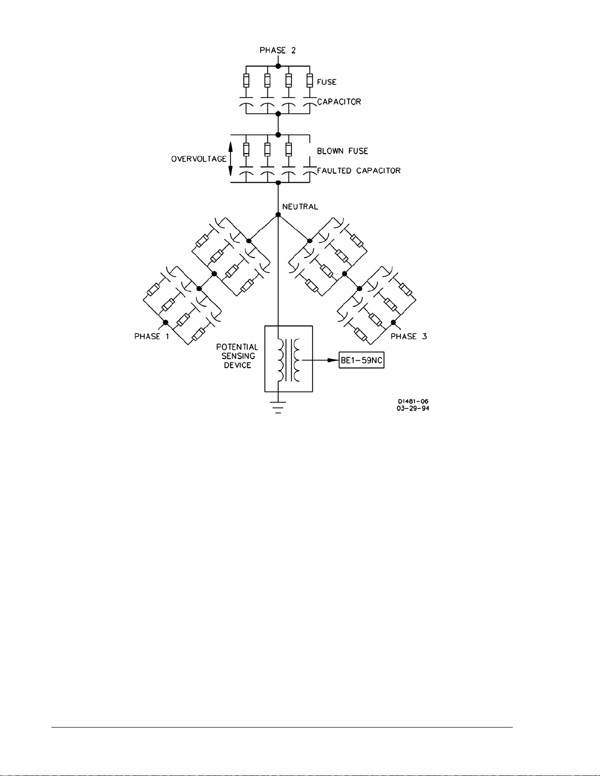
Figure 1-1. Ungrounded 3-Phase, 3-Wire Sys tem
Input Sensing
BE1-59NC Neutral O vervoltage relays receive the input signal from volta ge sensing devices connecte d
between the capacitor bank neutral and ground. These voltage sensing devices can be potential
transformers or resistor potential devices. Ideally, the voltage across each leg of a capacitor bank is
balanced, and the voltage from neutral to ground is zero. If a single capacitor fails and blows the
protecting fuse, an unbalanced condition occurs that shifts the neutral and creates a small but
measurable voltage. Through the potential sensing devices, the neutral relay senses this voltage
unbalance and reacts to g ive the appropriate signal (usual ly an alarm or trip depending on the vo ltage
level).
Further loss of more c apac it ors incr eas es the neutral voltage. T he r e lay sens es th i s voltage inc re as e, an d
reacts to give the appropr iate signa l. This signal is us ually a tr ip dep ending o n the voltage levels a nd how
the protection scheme is designed.
Alarms and Outputs
Sensitive settings on the relay are used as an a larm to alert that a fuse has blown and maintenance is
required. They woul d be typically set at a leve l corresponding to the vol tage rise caused by one b lown
fuse. The second out put would have a s etting that would be set to trip the capacitor bank off t he bus or
line when the voltage exce eds 110% of the nom inal capacitor bank volt age. This setting depe nds on the
capacitor bank size and configuration.
1-2 BE1-59NC General Information 9279400990 Rev D
Page 11
MODEL AND STYLE NUMBER
Electrical characteristics and operational features included in a specific relay are defined by a
combination of letters and numbers that make up the style number. Mod el number BE1-59NC designates
the relay as a Basler Electric Neutral Overvoltage Relay. The model number, together with the style
number, describes the options included in a specific device and appears on the front panel, draw-out
cradle, and inside the case assembly.
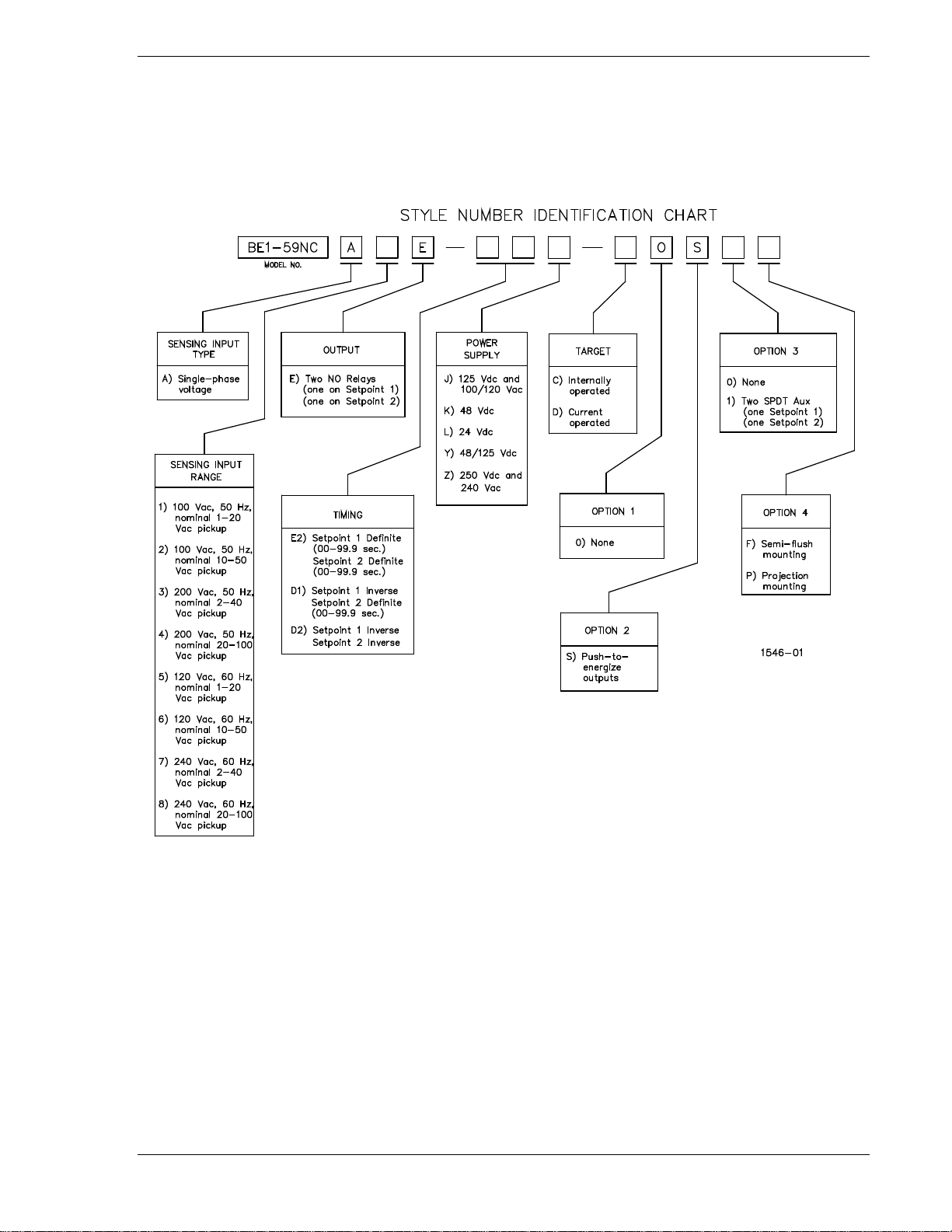
The style number identification chart for the BE1-59NC relay is illustr at ed in Figure 1-2.
Figure 1-2. Style Number Identification Chart
Style Number Example If a BE1-59NC relay has a style number of A5E–E2J–C0S1F, the relay has the following features: A -------- Single-phase voltage sensing
5 -------- 120 Vac, 60 Hz, nominal 1 to 20 Vac pickup
E -------- Two output relays with normally open contacts
E2 ------ Setpoint 1 Definite (0.1 to 99.9 sec.), Setpoint 2 Definite (0.1 to 99.9 sec.)
J -------- 125 Vdc or 100/120 Vac power supply
C -------- Internally opera ted tar gets
0 -------- None
S -------- Push-to-energize outputs
1 -------- Two SPDT auxiliary output relays, one for setpoint 1 and one for setpoint 2
F -------- Semi-flush mounting case
9279400990 Rev D BE1-59NC General Information 1-3
Page 12

SPECIFICATIONS
Electrical and physical specifications are listed in the following paragraphs.
Voltage Sensing
Maximum continuous rat ing : 36 0 V ac for 100 /12 0 V ac i nput, 48 0 Vac
for 200/240 Vac input, with a maximum burden of 2 VA.
Sensing Input Ranges
Ranges 1 and 5: 1 to 20 Vac pickup
Ranges 2 and 6: 10 to 50 Vac pickup
Ranges 3 and 7: 2 to 40 Vac pickup
Ranges 4 and 8: 20 to 100 Vac pickup
Pickup Accuracy
Ranges 1, 3, 5, or 7: ±2.0% or 100 millivolts, whichever is greater.
Ranges 2, 4, 6, or 8: ±2.0% or 200 millivolts, whichever is greater.
Dropout
98% of pickup within 7 cycles.
Timing Characteristics
Inverse: Response time decreases as the difference between the monitored
voltage and the setpoint increases. The inverse time char acteristics
switch is adjustable from 01 to 99 in 01 increments. Each position
corresponds to a specific curve except 0 0, which is instantaneous.
Accuracy is within ±5% or 25 milliseconds, whichever is greater.
Definite: Adjustable from 00.1 to 99.9 seconds, in steps of 0.1 seconds. (A
setting of 00.0 provides instantaneous timing.) Accuracy is within
±2% or 100 milliseconds, whichever is greater.
Output Contacts
Resistive Ratings
120 Vac: Make, break, and carry 7 Aac continuously
250 Vdc: Make and carry 30 Adc for 0.2 s, carry 7 Adc continuously,
break 0.3 Adc
500 Vdc: Make and carry 15 Adc for 0.2 s, carry 7 Adc continuously,
break 0.3 Adc
Inductive Ratings
120 Vac, 125 Vdc, 250 Vdc: Break 0.3 A (L/R = 0.04)
1-4 BE1-59NC General Information 9279400990 Rev D
Page 13

Power Supply
Input Voltage
K (midrange)
48 Vdc
24 to 150 Vdc
2.5 W
125 Vdc
24 to 150 Vdc
2.8 W
12 to 32 Vdc ∗
48 Vdc
24 to 150 Vdc
2.5 W
125 Vdc
24 to 150 Vdc
2.8 W
250 Vdc
68 to 280 Vdc
3.0 W
240 Vac
90 to 270 Vac
19.7 VA
Power supply types and specifications are listed in Table 1-1.
Table 1-1. Power Supply Ratings
Type
J (midrange)
L (low range) 24 Vdc
Y (midrange)
Z (high range)
∗ Type L power s upply initially requ ires 14 Vdc to b egin operat ing. Once operat ing, the input v oltage may
be reduced to 12 Vdc and operation will continue.
Target Indicators
Electronically latched, ma nually reset target indicat ors indicate closure of t he trip output contacts. Eit her
internally operated or current operated targets may be specified.
Current Operated Targets
Minimum Rating: 200 mA flowing through the trip circuit
Continuous Rating: 3 A
1 Second Rating: 30 A
2 Minute Rating: 7 A
Nominal
120 Vac 90 to 132 Vac 12.4 VA
Input Voltage Range Burden at Nominal
2.7 W
Type Tests
Shock: Withstands 15 G in each of three mutually perpendicular planes
without structural damage or performance degradation.
Vibration: Withstands 2 G in each of three mutually perpendicular planes,
swept over the range of 10 to 500 Hz for a total of six sweeps, 15
minutes each sweep, without structural damage or degradation of
performance.
Isolation: 1,500 Vac at 60 Hz for on e min ute in ac c ord anc e w ith I EC 255-5 and
ANSI/IEEE C37.90-1989 (Dielectric Test)..
Radio Frequency Interference: Field tested using a five-watt, hand-held transceiver operating at
random frequencies centered around 144 megahertz and 440
megahertz, with the antenna located six inches from the relay in both
horizontal and vertical planes.
Surge Withstand Capability: Qualified to IEEE C37.90.1-1989, Standard Surge Withstand
Capability (SWC) Tests for Protective Relays and Relay Systems.
Physical
Temperature
Operating Range: –40 to 70°C (–40 to 158°F)
Storage Range: –65 to 100°C (–85 to 212°F)
Weight: 13.5 lbs (6.12 kg)
Case Size: S1 (See Section 4 for panel cutting/drilling dimensions.)
9279400990 Rev D BE1-59NC General Information 1-5
Page 14

Agency Recognition/Certification
Gost-R Certification: GOST-R certified per the relevant standards of Gosstandart of
Russia.
CHARACTERISTIC CURVES
BE1-59NC overvoltage inv er se time curv es are illustr a ted in Figures 1-3 and 1-4.
Figure 1-3. Overvoltage Inverse Time Curves, Low Ranges
1-6 BE1-59NC General Information 9279400990 Rev D
Page 15

Figure 1-4. Overvoltage Inverse Time Curves, High Ranges
9279400990 Rev D BE1-59NC General Information 1-7
Page 16

This page intentionally left blank .
1-8 BE1-59NC General Information 9279400990 Rev D
Page 17

SECTION 2 • CONTROLS AND INDICATORS
Locator
Description
potentiometer that sets the
INTRODUCTION
Controls and indicators ar e located on the front panel. The contr ols and indicators are shown in Figure
2-1 and described in Table 2-1. Figure 2-1 illustrates a relay with the maximum number of controls and
indicators. Your relay may not have all of the controls and indicators shown and described here.
Figure 2-1. Location of Controls and Indicators
Table 2-1. Control and Indicator Descriptions
A
B
9279400990 Rev D BE1-59NC Controls and Indicators 2-1
OVERVOLTAGE 1 PICKUP Adjustment. A multiturn
overvoltage compara tor threshold voltage. C ontinuously adjusta ble for the sensing i nput
voltage range.
OVERVOLTAGE 1 PICKUP LED. A red LED that illuminates wh en overvoltage exc eeds
the pickup setting.
Page 18

Locator Description
potentiometer that sets the
C
D
E
F
G
H Target Reset Switch. Provides manual reset of the target ind ic ators (locator J).
I
J
OVERVOLTAGE 1 TIME DIAL. Thumbwheel switch that s elects the desired ov ervoltage
output delay (definite timing characteristic adjustable from 00 .1 to 99.9 seconds, in 0.1
second increments). A setting of 00 is instantaneous.
OVERVOLTAGE 2 PICKUP Adjustment. A multiturn
overvoltage compara tor threshold voltage. C ontinuously adjusta ble for the sensing i nput
voltage range.
OVERVOLTAGE 2 PICKUP LED. A re d LED that illuminates w hen overvoltage ex ceeds
the pickup setting.
OVERVOLTAGE 2 TIME DIAL. Thumbwhe el switch that selects t he desired overvoltage
output delay (definite timing characteristic adjustable from 00 .1 to 99.9 seconds, in 0.1
second increments). A setting of 00 is instantaneous.
POWER LED. LED illuminates when proper operating power is applied to the relay
internal circuitry.
PUSH TO ENERGIZE OUTPUTS. These pushbuttons allow manual actuation of the
output relays. Output relay actuation is achieved by inserting a nonconductive rod
through the front panel access holes.
Target Indicators. These e lectronically latched red target indicators illuminate when the
trip output relays energize. To ensure proper operation of a current-operated tar get, the
current flowing through the tr ip cir cuit mus t be 20 0 mA or higher. T h e target i ndic a t or s ar e
reset by operating the target reset switch (locator H).
2-2 BE1-59NC Controls and Indicators 9279400990 Rev D
Page 19

SECTION 3 • FUNCTIONAL DESCRIPTION
INTRODUCTION
BE1-59NC relay functions are illustrated in Figure 3-1 and described in the following paragraphs.
Figure 3-1. Function Block Diagram
FUNCTIONAL DESCRIPTION
Inputs
Sensed voltage developed across the input sensing device connected in the neutral-grounding current
transformer secondary is applied to the BE1-59NC Neutral Overvoltage Relay. Internal transformers
provide further isolati on and s tep down for the re lay logic c ircuits. BE1-59N C Neutr al Overvolt age Relays
may also be used in ungrounded systems with voltage transformers connected in wye/broken delta
configurations. Typica l connection methods are s hown in Section 4. Over voltage #1 and Overvoltag e #2
circuits are functionally the same except for timing characteristics.
Filters
Bandpass filters provide peak sensitivity at 50 or 60 hertz for the overvoltage #1 and overvoltage #2
inputs. Third harmonic rejection is 40 dB minimum.
Overvoltage Comparator
Each overvoltage compar ator circuit receiv es a sensing voltage fro m the bandpass filter and a reference
voltage from the fro nt pan el s etting. When t he in put exc eeds th e sett ing refer enc e, the comp arator output
enables the timing circuit and the OVERVOLTAGE PICKUP LED turns ON.
Definite Time Delay
An output signal from the comparator circuit ena bles a counting circuit to b e incremented by an intern al
clock. When the coun ting circuit re aches the count that matches th e number enter ed on the TIME DIA L,
the outpu t relay and auxiliary relay are ener gized. However, if the sensed inpu t voltage falls below the
pickup setting before the timer completes its cycle, the timer resets within 2.0 cycles.
9279400990 Rev D BE1-59NC Functional Description 3-1
Page 20

The definite time delay is adjustable from 00.1 to 99.9 seconds in 0.1 second increments. Fron t panel
mounted switches determine the delay. Position 00.0 is instantaneous.
Inverse Time Delay
Inverse time delay circuits are identical to definite time delay circuits except that a voltage controlled
oscillator (VCO) is subs tituted for the clock signal. Th e VCO is controlled by a voltage derived fr om the
sensed input. Beca use t he frequenc y of the os cillat or is kept pr oport ional to the s ensed in put v oltage, the
desired inverse time delay is produced.
Inverse time charac teristic c urve thum bwheel sw itches are s ettable fr om 01 to 99 in 01 incremen ts. Each
position corresponds to a specific curve setting except 00, which is instantaneous. Refer to Figures 1-3
and 1-4 to see the inverse time characteristic curves.
Reference Voltage Circuit
A constant voltage source provides a reference voltage to the potentiometers on the front panel. The
potentiometers, in turn, provide reference voltages to all the comparator circuits and establish the
threshold for each circuit.
Power Supply Status Output
The power supply status rel ay has a set of normally clos ed c ontacts an d e ner gizes when operating po w er
is applied to the relay. If re lay operating power is lost or either side o f the power supply ou tput (+12 Vdc
or –12 Vdc) fails, the pow er supply status rel ay de-energizes and closes the power supply s tatus output
contacts.
Power Supply
Operating power for the r el ay circ uitry is supplie d by a wide rang e, elec trica lly iso lated, low-b urden pow er
supply. Power supply operating power is not polarity sensitive. The front panel power LED and power
supply status output indicate when the power supply is operating. Power supply specifications are listed in
Table 1-1.
Target Indicators
Target indicators are optional components selected when a relay is ordered. The elect ronically latched
and reset targets consist of red LED indicators located on t he relay fr ont pane l. Latched target s are reset
by operating the target reset s witch on the front panel. If relay operating power is lost, any illuminated
(latched) targets are extin guishe d. When relay operating pow er is res tored, the prev iously latched tar gets
are restored to their latched state.
A relay can be equipped with either internally operated targets or current operated targets.
Internally Operated Targets
The relay trip outputs are directly applied to drive the target indicators. The indicators are illuminated
regardless of the current level in the trip circuits.
Current Operated Targets
Current operated targets are triggered by closure of the corresponding output contact and the presence of
at least 200 milliamperes of current flowing in the trip circuit.
NOTE
Prior to September 2007, the BE1-59NC target indicators consisted of
magnetically latched, disc indicators. These mechanically latched target
indicators have been replaced by the electronically latched LED targets in use
today.
3-2 BE1-59NC Functional Description 9279400990 Rev F
Page 21

SECTION 4 • INSTALLATION
INTRODUCTION
BE1-59NC relay s are ship ped in s turdy c arto ns to prevent d amage duri ng trans it. Upon r ece ipt of a relay ,
check the model an d style number a gainst the r equis ition and p acking l ist to s ee that they agree . Inspec t
the relay for shipping dama ge. If ther e is ev idenc e of d amage, f ile a cl aim wi th the carrier, an d notify your
sales representative or Basler Electric.
If the relay will not be installed immed iately, stor e it in its original shipp ing carton i n a moisture- and dustfree environment. Before placing the relay in service, it is recommended that the test procedures of
Section 5, Testing be performed.
RELAY OPERATING GUIDE L INES AND PRECAUTIONS
Before installing or operating the relay, not the following guidelines and precautions.
• For proper current operated target operation, a minimum current of 200 milliamperes must flow
through the output trip circuit.
• If a wiring insulation test is required, remove the connection plugs and withdraw the relay from its
case.
CAUTION
When the connection plugs are removed, the relay is disconnected from the
operating circuit and will not provide system protection. Always be sure that
external operating (mo nitored) conditions are stable b efore removing a relay for
inspection, test, or service.
NOTE
Be sure that the re lay is ha r d-wired to earth groun d with no smaller tha n 1 2 AWG
copper wire attached to th e ground terminal on the rear of the case. When the
relay is configured i n a system with other devices , it is recommended to use a
separate lead to the ground bus from each device.
MOUNTING
Because the relay is of solid-state design, it does not have to be mounted vertically. Any convenient
mounting angle may be c hosen. Relay outline dimensions and panel drilling diagrams are illustrated in
Figures 4-1 through 4-7.
9279400990 Rev D BE1-59NC Installation 4-1
Page 22

3.03 (77)
6.06 (154)
0.25 (6) diameter, 4 places
C
L
Cut-Out
0.575
(15)
8.63
(219)
0.552
(14)
5.69 (144)
Outer Edge of Cover
0.480
(12)
8.25
(210)
4.13
(105)
0.480
(12)
P0072-12
Figure 4-1. Panel Cutting/D rill ing, Semi-Flush, S1 Case
4-2 BE1-59NC Installation 9279400990 Rev D
Page 23

Figure 4-2. S1 Case Dimensions, Rear View, Double Ended, Semi-Flush Mount
9279400990 Rev D BE1-59NC Installation 4-3
Page 24

.75
(19.1)
(157.2)
6.19
(49.53)
1.95
10-32 SCREWS
(7.9)
.31
10-32 SCREWS
(102.4)
4.03
4.03
(102.4)
(7.9)
.31
MOUNTING PANEL
(55.75)
2.195
P0066-64
Figure 4-3. S1 Case Dimensions, Side View, Double Ended, Semi-Flush Mount
4-4 BE1-59NC Installation 9279400990 Rev D
Page 25

Figure 4-4. Panel Cutting/D rill ing, Doubl e End ed, Proj e c tion Mou nt, S1 Cas e
9279400990 Rev D BE1-59NC Installation 4-5
Page 26

Figure 4-5. S1 Case Dimensions, Rear View, Double Ended, Projection Mount
4-6 BE1-59NC Installation 9279400990 Rev D
Page 27

.75
(19.1)
(157.2)
6.19
(49.53)
1.95
10-32 SCREWS
(7.9)
.31
10-32 SCREWS
(102.4)
4.03
4.03
(102.4)
(7.9)
.31
(55.75)
2.195
P0066-67
TERMINAL EXTENSION (TYP.)
FOR DETAILED INSTRUCTIONS,
SEE THE TERMINAL PROJECTION
MOUNTING KIT SUPPLIED.
.25
(6.4)
5/16-18 STUD
2 PLACES
MOUNTING PANEL
Figure 4-6. S1 Case Dimensions, Side View, Double Ended, Projection Mount
9279400990 Rev D BE1-59NC Installation 4-7
Page 28

P00
66-68
Figure 4-7. S1 Case Cover Dimensions, Front View
4-8 BE1-59NC Installation 9279400990 Rev D
Page 29

CONNECTIONS
Be sure to check the model and style number of a relay before connecting and energizing the relay.
Incorrect wiring may r es u lt i n da mag e t o th e r e lay. Except where not ed, c o nnec t io ns s hou ld be mad e with
wire no smaller than 14 AWG.
Typical control circuit connections are shown in Figure 4-8. Typical protection methods are shown in
Figure 4-9. Typical internal connections are shown in Figure 4-10.
Figure 4-8. Typical Control Circ u it Connections
9279400990 Rev D BE1-59NC Installation 4-9
Page 30

Figure 4-9. Typical Protection Methods
4-10 BE1-59NC Installation 9279400990 Rev D
Page 31

Figure 4-10. Typical Internal Connections
9279400990 Rev D BE1-59NC Installation 4-11
Page 32

MAINTENANCE
BE1-59NC relays require no preventive m aintenance other than a per iodic operat ional check. If th e relay
fails to function properly, contact Technical Sales Support at Basler Electric to coordinate repairs.
STORAGE
This device contains long-life electrolytic capacitors. For devices that are not in service (spares in
storage), the life of thes e capacitors c an be maximize d by energizing t he device for 30 m inutes once per
year.
4-12 BE1-59NC Installation 9279400990 Rev D
Page 33

SECTION 5 • TESTING
INTRODUCTION
The following procedures verify proper relay operation and calibration.
Results obtained fr om thes e procedur es may no fall w ithin spec ified tol erances. When evalu ating resu lts,
consider three prominent factors:
• Test equipment accuracy
• Testing method
• External test set components tolerance level
REQUIRED TEST EQUIPMENT
Minimum test equipment required for relay testing and adjustment is listed below.
• Two Multi-Amp SSR-78 a nd a counter /timer acc urate to at l east 1.0% or o ne Doble F 2500 (has timer
included) or suitable substitute.
• Digital voltmeter accurate to within 1% or better.
• Variable AC/DC (0-250V) power supply (for power input).
• DC power supply (for current operated targets).
OPERATIONAL TEST
Step 1. Perform the appropriate test setup for your relay. Us e Figure 5-1 for timing opt ion E2 and F i gure
5-2 for timing options D1 or D2. On D1 , setpoi nt one is inverse t ime and s etpoint two is definite
time.
Step 2. Apply operating power to the relay, verify that the POWER LED is ON, and v erify that the power
supply status contact is open.
Step 3. Perform the following timing tests as appropriate for your relay.
E2 Timing Option
Step 1. Reference to Figure 5-1, connect an ac voltage source (50 or 60 Hz, depending upon input
option) to case termin als 6 and 7. Adjust this voltag e to equal the desired over voltage pickup
level for OVERVOLTAGE 1.
Step 2. Starting at maximum CW, slowly turn OVERVOLTAGE 1 PICKUP adjust potentiometer R63
CCW until OVERVOLTAGE 1 PICKUP LED just illuminates.
Step 3. Set OVERVOLTAGE 1 T IM E DIAL to 001 and a pply t o c ase term inals 6 an d 7, a voltag e that is
10% greater than the value applied in Step 1.
Step 4. Monitor the output term inals indicated in Figure 5-1 for OVERVOLTAGE 1. R emove, and then
reapply the overvoltag e at case terminals 6 a nd 7. Observe the tim e registered by the counter.
Time must equal the setting ±100 milliseconds or 2%, whichever is greater.
Step 5. Set OVERVOLTAGE 1 TI ME DIAL to 010. Monitor the out put terminals indicat ed in Figure 5-1
for OVERVOLTAGE 1. R emove, and then reap ply the overvoltage at case terminals 6 and 7.
Observe the time register ed by the counter. Time mus t equal the setting ±100 milliseconds or
2%, whichever is greater.
Step 6. Set OVERVOLTAGE 1 TI ME DIAL to 100. Monitor the out put terminals indicat ed in Figure 5-1
for OVERVOLTAGE 1. R emove, and then reap ply the overvoltage at case terminals 6 and 7.
Observe the time register ed by the counter. Time mus t equal the setting ±100 milliseconds or
2%, whichever is greater.
Step 7. Set OVERVOLTAGE 1 TI ME DIAL to 999. Monitor the out put terminals indicat ed in Figure 5-1
for OVERVOLTAGE 1. R emove, and then reap ply the overvoltage at case terminals 6 and 7.
Observe the time register ed by the counter. Time mus t equal the setting ±100 milliseconds or
2%, whichever is greater.
Step 8. Adjust the voltage source equal the desired overvoltage pickup level for OVERVOLTAGE 2.
Step 9. Starting at maximum CW, slowly turn OVERVOLTAGE 2 PICKUP adjust potentiometer R43
CCW until OVERVOLTAGE 2 PICKUP LED just illuminates.
9279400990 Rev D BE1-59NC Testing 5-1
Page 34

Step 10. Set OVERVOLTAGE 2 T IM E DIAL to 001 and a pply t o c ase term inals 6 an d 7, a voltage th at is
10% greater than the value applied in Step 1.
Step 11. Monitor the output term inals indicated in Figure 5-1 for OVERVOLTAGE 2. R emove, and then
reapply the overvoltag e at case terminals 6 a nd 7. Observe the tim e registered by the c ounter.
Time must equal the setting ±100 milliseconds or 2%, whichever is greater.
Step 12. Set OVERVOLTAGE 2 TI ME DIAL to 010. Monitor the out put terminals indicat ed in Figure 5-1
for OVERVOLTAGE 2. R emove, and then reapply th e overvoltage at case termina ls 6 and 7.
Observe the time register ed by the counter. Time mus t equal the setting ±100 milliseconds or
2%, whichever is greater.
Step 13. Set OVERVOLTAGE 2 TI ME DIAL to 100. Monitor the out put terminals indicat ed in Figure 5-1
for OVERVOLTAGE 2. R emove, and then reapply th e overvoltage at case termina ls 6 and 7.
Observe the time register ed by the counter. Time mus t equal the setting ±100 milliseconds or
2%, whichever is greater.
Step 14. Set OVERVOLTAGE 2 TI ME DIAL to 999. Monitor the out put terminals indicat ed in Figure 5-1
for OVERVOLTAGE 2. R emove, and then reapply th e overvoltage at case termina ls 6 and 7.
Observe the time register ed by the counter. Time mus t equal the setting ±100 milliseconds or
2%, whichever is greater.
Figure 5-1. Typical Test Setup Timing Option E2
5-2 BE1-59NC Testing 9279400990 Rev D
Page 35

D1 Timing Option
°
°
NOTE
In the following inverse tim e tests , voltage is steppe d from one-half of pickup to a
voltage that is high er (by value in c olumn for Volts O ver Pickup, Ta ble 5-1) than
the pickup.
Step 1. With reference to Figure 5-2, set PS1 for the va lue shown in Table 5-1, input opti on (column 1)
and for the specific pickup voltage (column 2, Volts Pickup 50/60 Hz). Example: input option 1,
PS1 set to 10 volts, at 0°.
Table 5-1. Inverse Time Overvoltage Levels and Delays for Input Options
Input Option
(Style NO.
nd
Digit)
2
1 10
2 30
3 21
4 60
5 10
6 30
7 21
8 60
Volts
Pickup
50/60 Hz
PS1
50/60 Hz
Volts @
50/60 Hz
Volts @
PS2
5 @ 0° 13 @ 0°
15 @ 0° 23 @ 0°
10.5 @ 0° 26.5 @ 0°
30 @ 0° 46 @ 0°
5 @ 0° 13 @ 0°
15 @ 0° 23 @ 0°
10.5 @ 0° 26.5 @ 0°
30 @ 0° 46 @ 0°
Volts
Over
Pickup
11
(Sec.)
8 0.612 1.545 2.478 3.876
8 0.582 1.534 2.487 3.916
16 0.612 1.545 2.478 3.876
16 0.582 1.534 2.487 3.916
8 0.612 1.545 2.478 3.876
8 0.582 1.534 2.487 3.916
16 0.612 1.545 2.478 3.876
16 0.582 1.534 2.487 3.916
TIME DIAL
33
(Sec.)
55
(Sec.)
88
(Sec.)
Step 2. Adjust the OVERVOLTAGE 1 PICKUP adjust potentiometer R63 so the OVERVOLTAGE 1
PICKUP LED just illuminates.
Step 3. Adjust PS1 and PS2 for the voltage leve ls and phase ang les based on input options as shown
in Table 5-1 (columns 3 and 4).
Step 4. Set the OVERVOLTAGE 1 TIME DIAL to 11.
Step 5. Reset the timer. Turn on P S1. While monitor ing the output termina ls indicated in Figure 5-1 for
OVERVOLTAGE 1, initiate PS2 and record the t ime delay. V erify that the tim e is within 5.0% or
25 milliseconds (whichever is greater) of the time shown in Table 5-1.
Step 6. Remove PS1 and PS2 voltage.
Step 7. Set the OVERVOLTAGE 1 TIME DIAL to 33.
Step 8. Reset the timer. Turn on P S1. While monitor ing the output termina ls indicated in Figure 5-1 for
OVERVOLTAGE 1, initiate PS2 and record the t ime delay. V erify that the tim e is within 5.0% or
25 milliseconds (whichever is greater) of the time shown in Table 5-1.
Step 9. Remove PS1 and PS2 voltage.
Step 10. Set the OVERVOLTAGE 1 TIME DIAL to 88.
Step 11. Reset the timer. Turn on P S1. While monitor ing the output termina ls indicated in Figure 5-1 for
OVERVOLTAGE 1, initiate PS2 and record the t ime delay. V erify that the tim e is within 5.0% or
25 milliseconds (whichever is greater) of the time shown in Table 5-1.
Step 12. Remove PS1 and PS2 voltage.
Step 13. Adjust the voltage source to equal the desired overvoltage pickup level for OVERVOLTAGE 2.
9279400990 Rev D BE1-59NC Testing 5-3
Page 36

Step 14. Starting at maximum CW, slowly turn OVERVOLTAGE 2 PICKUP adjust potentiometer R43
CCW until OVERVOLTAGE 2 PICKUP LED just illuminates.
Step 15. Set OVERVOLTAGE 2 T IM E DIAL to 001 and a pply t o c ase term inals 6 an d 7, a voltage th at is
10% greater than the value applied in Step 13.
Step 16. Monitor the output terminals indicated in Figure 5-1 for OVERVOLTAGE 2. Remove, then
reapply the overvoltag e at case terminals 6 a nd 7. Observe the tim e registered by the c ounter.
Time must equal the setting ±100 milliseconds or 2%, whichever is greater.
Step 17. Set OVERVOLTAGE 2 TI ME DIAL to 010. Monitor the out put terminals indicat ed in Figure 5-1
for OVERVOLTAGE 2. R emove, and then reapply th e overvoltage at case termina ls 6 and 7.
Observe the time register ed by the counter. Time mus t equal the setting ±100 milliseconds or
2%, whichever is greater.
Step 18. Set OVERVOLTAGE 2 TI ME DIAL to 100. Monitor the out put terminals indicat ed in Figure 5-1
for OVERVOLTAGE 2. R emove, and then reapply th e overvoltage at case termina ls 6 and 7.
Observe the time register ed by the counter. Time mus t equal the setting ±100 milliseconds or
2%, whichever is greater.
Step 19. Set OVERVOLTAGE 2 TI ME DIAL to 999. Monitor the out put terminals indicat ed in Figure 5-1
for OVERVOLTAGE 2. R emove, and then reapply th e overvoltage at case termina ls 6 and 7.
Observe the time register ed by the counter. Time mus t equal the setting ±100 milliseconds or
2%, whichever is greater.
Figure 5-2. Typical Test Setup Timing Options D1 or D2
5-4 BE1-59NC Testing 9279400990 Rev D
Page 37

NOTE
In the following inverse tim e tests , voltage is steppe d from one-half of pickup to a
voltage that is high er (by value in c olumn for Volts Over Pickup, T able 5-1) than
the pickup.
D2 Timing Option
Step 1. With reference to Figure 5-2, set PS1 for the va lue shown in Table 5-1, input opti on (column 1)
and for the specific pickup voltage (column 2, Volts Pickup 50/60 Hz). Example: input option 1,
PS1 set to 10 volts, at 0°.
Step 2. Adjust the OVERVOLTAGE 1 PICKUP adjust potentiometer R63 so the OVERVOLTAGE 1
PICKUP LED just illuminates.
Step 3. Adjust PS1 and PS2 for the voltage leve ls and phase ang les based on input options as shown
in Table 5-1 (columns 3 and 4).
Step 4. Set the OVERVOLTAGE 1 TIME DIAL to 11.
Step 5. Reset the timer. Turn on P S1. While monitor ing the output termina ls indicated in Figure 5-2 for
OVERVOLTAGE 1, initiate PS2 and record the t ime delay. V erify that the tim e is within 5.0% or
25 milliseconds (whichever is greater) of the time shown in Table 5-1.
Step 6. Remove PS1 and PS2 voltage.
Step 7. Set the OVERVOLTAGE 1 TIME DIAL to 33.
Step 8. Reset the timer. Turn on P S1. While monitor ing the output termina ls indicated in Figure 5-2 for
OVERVOLTAGE 1, initiate PS2 and record the t ime delay. V erify that the tim e is within 5.0% or
25 milliseconds (whichever is greater) of the time shown in Table 5-1.
Step 9. Remove PS1 and PS2 voltage.
Step 10. Set the OVERVOLTAGE 1 TIME DIAL to 88.
Step 11. Reset the timer. Turn on P S1. While monitor ing the output termina ls indicated in Figure 5-2 for
OVERVOLTAGE 1, initiate PS2 and record the t ime delay. V erify that the tim e is within 5.0% or
25 milliseconds (whichever is greater) of the time shown in Table 5-1.
Step 12. Remove PS1 and PS2 voltage.
Step 13. With reference to Figure 5-2, set PS 1 for the va lue sh own in Table 5-1 an d for th e specific i nput
option.
Step 14. Adjust the OVERVOLTAGE 2 PICKUP adjust potentiometer R43 so the OVERVOLTAGE 2
PICKUP LED just illuminates.
Step 15. Adjust PS1 and PS2 for the voltage leve ls and phase ang les based on input opt ions as shown
in Table 5-1.
Step 16. Set the OVERVOLTAGE 2 TIME DIAL to 11.
Step 17. Reset the timer. Turn on P S1. While monitor ing the output termina ls indicated in Figure 5-2 for
OVERVOLTAGE 2, initiate PS2 and record the t ime delay. V erify that the tim e is within 5.0% or
25 milliseconds (whichever is greater) of the time shown in Table 5-1.
Step 18. Remove PS1 and PS2 voltage.
Step 19. Set the OVERVOLTAGE 2 TIME DIAL to 33.
Step 20. Reset the timer. Turn on P S1. While monitor ing the output termina ls indicated in Figure 5-2 for
OVERVOLTAGE 2, initiate PS2 and record the t ime delay. V erify that the tim e is within 5.0% or
25 milliseconds (whichever is greater) of the time shown in Table 5-1.
Step 21. Remove PS1 and PS2 voltage.
Step 22. Set the OVERVOLTAGE 2 TIME DIAL to 88.
Step 23. Reset the timer. Turn on P S1. While monitor ing the output termina ls indicated in Figure 5-2 for
OVERVOLTAGE 2, initiate PS2 and record the t ime delay. V erify that the tim e is within 5.0% or
25 milliseconds (whichever is greater) of the time shown in Table 5-1.
Step 24. Remove PS1 and PS2 voltage.
9279400990 Rev D BE1-59NC Testing 5-5
Page 38

This page intentionally left blank .
5-6 BE1-59NC Testing 9279400990 Rev D
Page 39

Page 40

12570 State R oute 143
Highland IL 62249-1074 USA
Tel: +1 618.654.23 4 1
Fax: +1 618.654.2351
email: info@basler.com
P.A.E. Les Pins
67319 Wasselonne Cedex
FRANCE
Tel: +33 3.88.87.1010
Fax: +33 3.88. 87.0808
email: franceinfo@basler.com
No. 59 Heshun Road Loufeng District (N)
Suzhou Indus trial Park
215122 Suzhou
P.R. CHINA
Tel: +86 512.8227.2888
Fax: +86 512.8227.2887
email: chinainfo@basler.com
111 North Bridge Road
15-06 Peninsul a Plaz a
Singapore 1 79098
Tel: +65 68.4 4.6445
Fax: +65 68.44.8902
email: singaporeinfo@basler.com
 Loading...