

Page 1
INSTRUCTION MANUAL
FOR
GROUND FAULT OVERVOLTAGE RELAY
BE1-59N
Publication: 9171400990
Revision: K 10/13
Page 2

Page 3

INTRODUCTION
This instruction manual provides information about the operation and installation of the BE1-59N Ground
Fault Overvoltage Relay. To accomplish this, the following information is provided:
• General Information and Specifications
• Controls and Indicators
• Functional Description
• Installation
• Testing
WARNING!
To avoid personal injury or equipment damage, only qualified personnel should
perform the procedures in this manual.
NOTE
Be sure that the relay is hard-wired to earth ground with no smaller than 12 AWG
copper wire attached to the ground terminal on the rear of the unit case. When
the relay is configured in a system with other devices, it is recommended to use a
separate lead to the ground bus from each unit.
9171400990 Rev K BE1-59N Introduction i
Page 4

First Printing: November 1986
Printed in USA
© 2013 Basler Electric, Highland Illinois 62249 USA
All Rights Reserved
October 2013
CONFIDENTIAL INFORMATION
of Basler Electric, Highland Illinois, USA. It is loaned for confidential use, subject
to return on request, and with the mutual understanding that it will not be used in
any manner detrimental to the interest of Basler Electric.
It is not the intention of this manual to cover all details and variations in equipment, nor does this manual
provide data for every possible contingency regarding installation or operation. The availability and design
of all features and options are subject to modification without notice. Should further information be
required, contact Basler Electric.
BASLER ELECTRIC
12570 STATE ROUTE 143
HIGHLAND IL 62249 USA
http://www.basler.com, info@basler.com
PHONE +1 618.654.2341 FAX +1 618.654.2351
ii BE1-59N Introduction 9171400990 Rev K
Page 5

REVISION HISTORY
Revision and Date
Change
The following information provides a historical summary of the changes made to the BE1-59N instruction
manual (9171400990). Revisions are listed in reverse chronological order.
Manual
K, 10/13
J, 01/2013
I
H, 04/09
G, 09/07
F, 04/02
E, 12/01
D, 01/93
C
B
A
—, 11/86
• Added instantaneous timing characteristic for 50-Hz relays.
• Updated case and cover drawings in Section 4.
• This revision letter not used.
• Corrected misalignment of data columns below Figure 1-4.
• Updated Storage statement in Section 4, Installation.
• Updated Output Contact ratings in Section 1.
• Moved content of Section 6, Manual Change Information to Manual
Introduction.
• Updated front panel illustrations to show laser graphics.
• Moved Testing content of Section 4, Installation to Section 5, Testing.
• Added manual part number and revision to all footers.
• Updated power supply burden data in Section 1.
• Updated Target Indicator description in Section 3.
• Added GOST-R to Section 1, General Information.
• Revised the power supply information in Sections 1 and 3.
• Updated power supply information in the style chart on page 1-3 and
in the example on page 1-2.
• Updated pickup voltage ranges and accuracies on page 1-4.
• Updated power supply description paragraphs on page 3-3.
• Updated unit case covers on pages 4-9 and 4-10.
• Updated drawings of front cover to show the new pushbutton
switches instead of the thumbwheel switches.
• New style chart (new option 1-2 and expanded option 1-1).
• Restructured the entire manual to conform to manual updates.
• Accuracy specification for the Definite Timing Characteristic was
clarified and upgraded on page 1-4.
• Output contact specifications were updated.
• Incorporated new timing option F7 in the manual.
• K was clarified for the various options on page 2-3.
• Accuracy specification for the Inverse Timing Characteristic was
clarified and upgraded on page 1-4.
• Initial release
9171400990 Rev K BE1-59N Introduction iii
Page 6

This page intentionally left blank.
iv BE1-59N Introduction 9171400990 Rev K
Page 7

CONTENTS
SECTION 1 • GENERAL INFORMATION ................................................................................................ 1-1
PURPOSE ........................................................................................................................................... 1-1
APPLICATION .................................................................................................................................... 1-1
High Resistance Grounding .......................................................................................................... 1-1
Ungrounded Systems ................................................................................................................... 1-2
MODEL AND STYLE NUMBER .......................................................................................................... 1-2
Style Number Example ................................................................................................................. 1-3
SPECIFICATIONS .............................................................................................................................. 1-3
Voltage Sensing Inputs ................................................................................................................. 1-3
Undervoltage Sensing Input Range ............................................................................................. 1-4
Pickup Accuracy ........................................................................................................................... 1-4
Dropout ......................................................................................................................................... 1-4
Timing Characteristics .................................................................................................................. 1-4
Output Contacts ............................................................................................................................ 1-4
Power Supply................................................................................................................................ 1-5
Target Indicators ........................................................................................................................... 1-5
Type Tests .................................................................................................................................... 1-5
Physical ........................................................................................................................................ 1-6
Agency Recognition/Certification.................................................................................................. 1-6
SECTION 2 • CONTROLS AND INDICATORS ....................................................................................... 2-1
INTRODUCTION ................................................................................................................................. 2-1
SECTION 3 • FUNCTIONAL DESCRIPTION ........................................................................................... 3-1
INTRODUCTION ................................................................................................................................. 3-1
INPUTS ............................................................................................................................................... 3-1
FILTERS ............................................................................................................................................. 3-1
OVERVOLTAGE COMPARATOR ...................................................................................................... 3-1
DEFINITE TIME DELAY (OPTIONAL) ................................................................................................ 3-1
INVERSE TIME DELAY (OPTIONAL) ................................................................................................ 3-2
REFERENCE VOLTAGE CIRCUIT .................................................................................................... 3-2
UNDERVOLTAGE ELEMENT (OPTIONAL)....................................................................................... 3-2
Undervoltage Operation ............................................................................................................... 3-2
Undervoltage Inhibit ...................................................................................................................... 3-2
OUTPUTS ........................................................................................................................................... 3-2
PUSH-TO-ENERGIZE OUTPUT PUSHBUTTONS ............................................................................ 3-2
POWER SUPPLY STATUS OUTPUT ................................................................................................ 3-3
POWER SUPPLY ............................................................................................................................... 3-3
TARGET INDICATORS ...................................................................................................................... 3-3
Internally Operated Targets .......................................................................................................... 3-3
Current Operated Targets ............................................................................................................ 3-3
SECTION 4 • INSTALLATION.................................................................................................................. 4-1
INTRODUCTION ................................................................................................................................. 4-1
RELAY OPERATING GUIDELINES AND PRECAUTIONS ............................................................... 4-1
MOUNTING ......................................................................................................................................... 4-1
CONNECTIONS .................................................................................................................................. 4-9
MAINTENANCE ................................................................................................................................ 4-12
STORAGE ......................................................................................................................................... 4-12
SECTION 5 • TESTING ............................................................................................................................ 5-1
INTRODUCTION ................................................................................................................................. 5-1
OPERATIONAL TEST ........................................................................................................................ 5-1
9171400990 Rev K BE1-59N Introduction v
Page 8

This page intentionally left blank.
vi BE1-59N Introduction 9171400990 Rev K
Page 9

SECTION 1 • GENERAL INFORMATION
R
Vpri
V
=
2
sec)(
PURPOSE
The available fault current for single-phase-to-ground faults is very limited for ungrounded systems and
systems, which are grounded through a high resistance. This current limiting reduces the possibility of
extensive equipment damage, and eliminates the need for a neutral breaker by reducing the fault current
below the level required to sustain an arc. However, it remains important to detect and isolate singlephase-to-ground faults in order to prevent their evolution into more dangerous faults such as phase-tophase-to-ground and three-phase-to-ground faults. Sensitive voltage relays can be used to detect ground
faults where the fault current is very small. The BE1-59N Ground Fault Overvoltage Relay is especially
suited to this task.
APPLICATION
High Resistance Grounding
A common method of grounding an ac generator is to connect a distribution transformer between the
neutral of the generator and the station ground. The distribution transformer's primary voltage rating is
equal to, or greater than, the generators rated line-to-neutral voltage. The distribution transformer
secondary is rated at 200/240 Vac or 100/120 Vac, and a resistor is connected across the secondary
winding. When reflected through the transformer, the resistor is effectively a high resistance.
Where: Rp is the effective primary resistance
R
N is the turns ratio of the distribution transformer
To determine resistor sizing:
• Determine the thermal limit P (in watts) of the voltage transformers.
is the actual value of the secondary resistor
s
Rp = Rs x N2
• Use
120V VT secondary in a worst-case condition.
• Size the watt rating of the resistor for 1/3 of the VT thermal limit to keep the resistor from excessive
heating. A smaller watt rating can be used if tripping for a ground condition.
Available single-phase-to-ground fault current at the generator terminals is greatly reduced by the high
effective resistance of the distribution transformer and secondary resistor. The distribution transformer
provides isolation for the protection scheme and reduces the voltage to a convenient level.
The BE1-59N Ground Fault Overvoltage Relay is connected across the secondary resistor to detect the
increase in voltage across the distribution transformer caused by a ground fault in the generator stator
windings. A ground fault at the generator terminals will result in rated line-to-neutral voltage across the
transformer primary, while ground faults near the neutral will result in lower voltages. The overvoltage
relay setpoint must be higher than any neutral voltage caused by normal unbalances in order to avoid
nuisance trips. This will allow a certain percentage of the stator windings to go unprotected by the
overvoltage relay. The overvoltage relay function typically protects 90 to 95% of the generator stator
windings.
The BE1-59N Ground Fault Overvoltage Relay monitors the fundamental frequency (50 or 60 Hz) voltage,
which accompanies a ground fault, but is insensitive to the third harmonic voltage present during normal
operation. One hundred percent protection of the generator stator windings is obtainable with the optional
overlapping undervoltage element. The under voltage element is tuned to the third harmonic voltage
which is present in the generator neutral under normal conditions. The undervoltage element detects the
reduction of the normal third harmonic voltage, which accompanies a ground fault near the neutral point
of the generator.
An undervoltage inhibit feature is included with the third harmonic undervoltage element. This feature
supervises the operation of the ground fault relay to prevent operation during startup and shutdown by
monitoring the generator terminal voltage.
to determine resistance in ohms, where Vsec = 120 x 3 = 360V. This assumes a
9171400990 Rev K BE1-59N General Information 1-1
Page 10
Ungrounded Systems
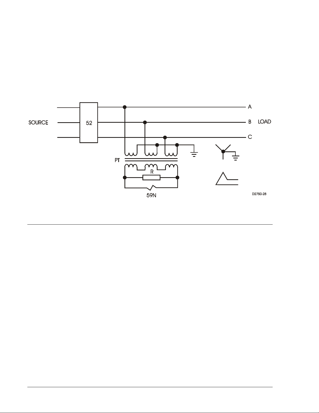
The BE1-59N Ground Fault Overvoltage Relay is used to detect ground faults on ungrounded threephase-three-wire systems. The relay is connected as shown in Figure 1-1 . A set of voltage transformers
are wired with a grounded wye primary and a broken delta secondary. The BEl-59N is connected across
the broken delta. It is often necessary to connect a resistor across the broken delta to avoid
ferroresonance.
Grounded wye/broken delta voltage transformers act as a zero sequence filters by summing the three
phase voltages. Under normal conditions, this sum is zero. When a ground fault occurs, the BE1-59N
Ground Fault Overvoltage Relay will detect the presence of the secondary zero sequence voltage (3V
).
O
The BE1-59N Ground Fault Overvoltage Relay greatly reduces the risk of equipment damage by
detecting and isolating the first ground on an ungrounded system.
Figure 1-1. Ungrounded 3-Phase, 3-Wire System
MODEL AND STYLE NUMBER
BE1-59N electrical characteristics and operational features are defined by a combination of letters and
numbers that make up the style number. Model number BE1-59N designates the relay as a Basler
Electric Ground Fault Overvoltage Protective Relay. The model number, together with the style number,
describes the options included in a specific device and appears on the front panel, draw-out cradle, and
inside the case assembly.
The style number identification chart for the BE1-59N relay is illustrated in Figure 1-2.
1-2 BE1-59N General Information 9171400990 Rev K
Page 11
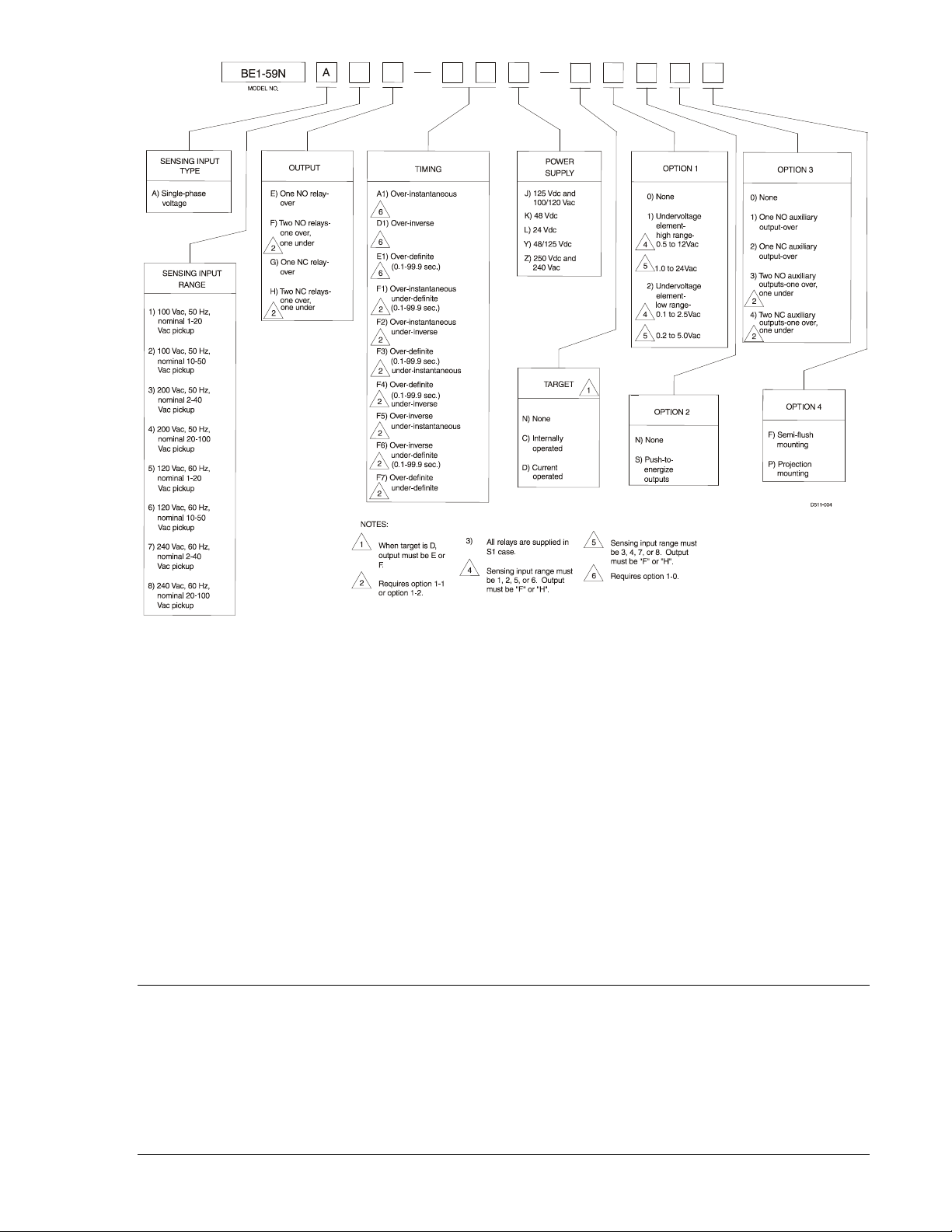
Figure 1-2. BE1-59N Style Identification Chart
Style Number Example
If a BE1-59N relay has a style number of A5F–F6J–D2S3F, the relay has the following features:
A -------- Single-phase voltage sensing input
5 -------- 120 Vac, 60 Hz nominal sensing voltage input with 1 to 20 Vac pickup range
F -------- Two output relays with normally open (NO) contacts (one overvoltage and one undervoltage)
F6 ------ Inverse time delay for overvoltage and definite time delay for undervoltage
J -------- Relay control power is 125 Vdc or 120 Vac, nominal
D -------- Two current operated target indicators (one per function)
2 -------- Undervoltage element range 0.1 to 2.5 Vac (low range with sensing input 5)
S -------- Push-to-energize outputs
3 -------- Two normally-open auxiliary output relays (one per function)
F -------- Semi-flush mounting case
SPECIFICATIONS
BE1-59N electrical and physical specifications are listed in the following paragraphs.
Voltage Sensing Inputs
Maximum continuous rating: 360 Vac for 100/120 Vac input, 480 Vac for 200/240 Vac input, with a
maximum burden of 2 VA for each input.
9171400990 Rev K BE1-59N General Information 1-3
Page 12

Undervoltage Sensing Input Range
High Range: 0.5 to 12 Vac (sensing input range 1, 2, 5, or 6) or 1.0 to 24 Vac
(sensing input range 3, 4, 7, or 8).
Low Range: 0.1 to 2.5 Vac (sensing input range 1, 2, 5, or 6) or 0.2 to 5.0 Vac
(sensing input range 3, 4, 7, or 8).
Pickup Accuracy
1 to 24 Vac range: ±2% or 20 millivolts
All other ranges: ±2% or 10 millivolts
Overvoltage Sensing Input Range
Ranges selectable by unit type for 50 or 60 Hz operation: 1 to 20 Vac, 10 to 50 Vac, 2 to 40 Vac, 20 to
100 Vac.
Pickup Accuracy
120 Vac (sensing input range 1, 2, 5, or 6): ±2% or 100 millivolts, whichever is greater
240 Vac (sensing input range 3, 4, 7, or 8): ±2% or 200 millivolts, whichever is greater
Dropout
98% of pickup within 7 cycles.
Timing Characteristics
Instantaneous: Less than 70 milliseconds (60-Hz relays) or less than 84 milliseconds
(50-Hz relays) for a voltage level that exceeds the pickup setting by
5% or 1 volt, whichever is greater
Definite: Adjustable from 00.1 to 99.9 seconds, in steps of 0.1 seconds.
Accuracy is within 2% or 100 milliseconds, whichever is greater. (A
setting of 00.0 provides instantaneous timing.)
Inverse: Response time decreases as the difference between the monitored
voltage and the setpoint increases. The inverse time characteristics
switch is adjustable from 01 to 99 in 01 increments. Each position
corresponds to a specific curve except 00, which is instantaneous.
Accuracy is within ±5% or 25 milliseconds (whichever is greater) of
the indicated time for any combination of the time dial and within
±2% of the voltage magnitude or 100 millivolts (for the 120 Vac
sensing range) or 200 millivolts (for the 240 Vac sensing range)
(whichever is greater) from the actual pickup value. Inverse time is
repeatable within ±2% or 25 milliseconds (whichever is greater) for
any time dial or pickup setting. The characteristic curves are defined
in Figures 1-3 and 1-4.
Output Contacts
Resistive Ratings
120 Vac: Make, break, and carry 7 Aac continuously
250 Vdc: Make and carry 30 Adc for 0.2 s, carry 7 Adc continuously,
break 0.3 Adc
500 Vdc: Make and carry 15 Adc for 0.2 s, carry 7 Adc continuously,
break 0.3 Adc
Inductive Ratings
120 Vac, 125 Vdc, 250 Vdc: Break 0.3 A (L/R = 0.04)
1-4 BE1-59N General Information 9171400990 Rev K
Page 13

Power Supply
Input Voltage
K (midrange)
48 Vdc
24 to 150 Vdc
3.4 W
125 Vdc
24 to 150 Vdc
3.6 W
120 Vac
90 to 132 Vac
22.1 VA
L (low range)
24 Vdc
12 to 32 Vdc ∗
3.5 W
48 Vdc
24 to 150 Vdc
3.4 W
125 Vdc
24 to 150 Vdc
3.6 W
250 Vdc
68 to 280 Vdc
3.7 W
240 Vac
90 to 270 Vac
37.6 VA
Power supply types and specifications are listed in Table 1-1.
Table 1-1. Power Supply Ratings
Type
J (midrange)
Y (midrange)
Z (high range)
∗ Type L power supply initially requires 14 Vdc to begin operating. Once operating, the input voltage may
be reduced to 12 Vdc and operation will continue.
Target Indicators
Electronically latched, manually reset target indicators are optionally available to indicate closure of the
trip output contacts. Either internally operated or current operated targets may be specified. Internally
operated targets should be selected when normally closed (NC) output contacts are specified.
Current Operated Targets
Minimum Rating: 200 mA flowing through the trip circuit
Continuous Rating: 3 A
1 Second Rating: 30 A
2 Minute Rating: 7 A
Nominal
Input Voltage Range Burden at Nominal
Type Tests
Shock: Withstands 15 G in each of three mutually perpendicular planes
without structural damage or performance degradation.
Vibration: Withstands 2 G in each of three mutually perpendicular planes,
swept over the range of 10 to 500 Hz for a total of six sweeps, 15
minutes each sweep, without structural damage or degradation of
performance.
Dielectric Strength: Tested in accordance with IEC 255-5 and IEEE C37.90: 2,000 Vac
applied for 1 min
Radio Frequency Interference: Field tested using a five watt, hand-held transceiver operating at
random frequencies centered around 144 MHz and 440 MHz, with
the antenna located six inches from the relay in both horizontal and
vertical planes.
Surge Withstand Capability: Qualified to IEEE C37.90.1-1989, Standard Surge Withstand
Capability (SWC) Tests for Protective Relays and Relay Systems.
Physical
Temperature
Operating Range: –40 to 70°C (–40 to 158°F)
Storage Range: –65 to 100°C (–85 to 212°F)
Weight: 13.6 lb (6.17 kg)
Case Size: S1 (See Section 4 for panel cutting/drilling dimensions.)
9171400990 Rev K BE1-59N General Information 1-5
Page 14

Agency Recognition/Certification
P0050-21
Voltage Difference from Pickup
UL Recognition: UL recognized per Standard 508, File E97033
NOTE: Output contacts are not UL recognized for voltages greater
than 250 volts.
Gost-R Certification: Gost-R certified per the relevant standards of Gosstandart of Russia.
Figure 1-3. Overvoltage Inverse Time Curves
1-6 BE1-59N General Information 9171400990 Rev K
Page 15

SCALE A
SCALE B
SCALE C
SCALE D
2.4 2.2 2.0 1.8 1.6 1.4 1.2 1.0 0.8 0.6 0.4
4.8 4.4 4.0 3.6 3.2 2.8 2.4 2.0 1.6 1.2 0.8
12 11 10 9 8 7 6 5 4 3 2
24 22 20 18 16 14 12 10 8 6 4
0.2
0.4
1
2
Voltage Difference from Pickup
Figure 1-4. Undervoltage Inverse Time Curves
9171400990 Rev K BE1-59N General Information 1-7
Page 16

This page intentionally left blank.
1-8 BE1-59N General Information 9171400990 Rev K
Page 17

SECTION 2 • CONTROLS AND INDICATORS
INTRODUCTION
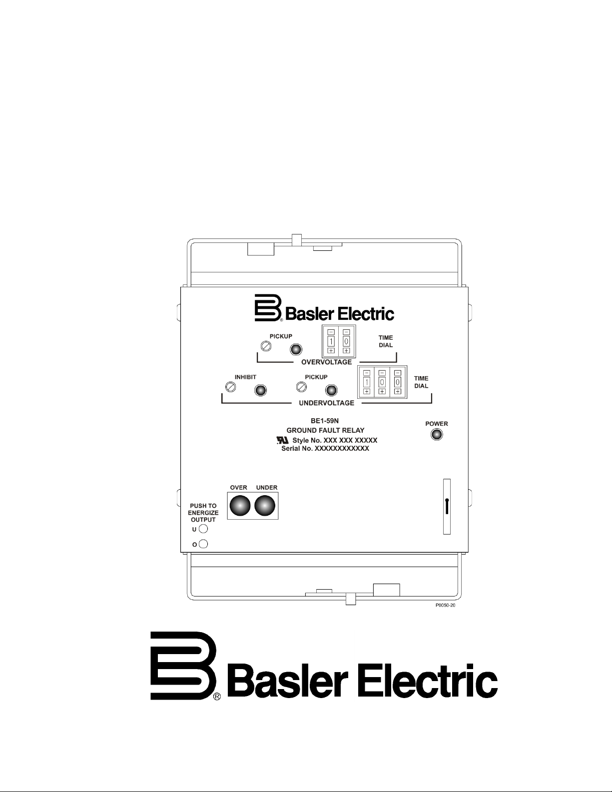
All BE1-59N controls and indicators are located on the front panel. The controls and indicators are shown
in Figure 2-1 and described in Table 2-1. Figure 2-1 illustrates a relay with the maximum number of
controls and indicators. Your relay may not have all of the controls and indicators shown and described
here.
Figure 2-1. BE1-59N Controls and Indicators
Table 2-1. Control and Indicator Descriptions
Locator Description
A
B
C
9171400990 Rev K BE1-59N Controls and Indicators 2-1
Overvoltage Pickup Adjustment. A multiturn potentiometer that sets the overvoltage
comparator threshold voltage. Continuously adjustable over the range indicated by the
style chart.
Overvoltage Pickup LED. A red LED that illuminates when overvoltage exceeds the
pickup setting.
Overvoltage Time Dial. Pushbutton switch that selects the desired overvoltage output
delay, either definite time (from 00.1 to 99.9 seconds) or, inverse time (characteristic
curves 01 through 99). A setting of 00 is instantaneous in either case.
Page 18

Locator Description
D
E Power Indicator. This red LED lights when operating power is applied to the relay.
F Target Reset Switch. This switch is operated to reset the target indicators.
G
H
I
J
K
L
Undervoltage Time Dial. Pushbutton switch that selects the desired overvoltage output
delay, either definite time (from 00.1 to 99.9 seconds) or, inverse time (characteristic
curves 01 through 99). A setting of 00 is instantaneous in either case.
Target Indicators. The electronically latched red target indicators illuminate when the
corresponding output relay energizes. To ensure proper operation of current-operated
targets, the current flowing through the trip circuit must be 200 mA or higher. Target
indicators are reset by operating the target reset switch (locator F).
Output Test Pushbuttons. These pushbuttons allow manual actuation of the output relays.
Output relay actuation is achieved by inserting a nonconductive rod through the front
panel access holes.
Undervoltage Pickup LED. A red LED that illuminates when undervoltage exceeds the
pickup setting.
Undervoltage Pickup Adjustment. A multiturn potentiometer that sets the undervoltage
comparator threshold voltage. Continuously adjustable over the range indicated by the
style chart.
Inhibit LED. A red LED that illuminates when the monitored generator voltage is under the
inhibit set point.
Inhibit Pickup Adjustment. Multiturn potentiometer that sets the inhibit comparator
threshold so that whenever generator voltage falls below the set point, the (optional)
undervoltage measuring circuitry is inhibited from operation.
2-2 BE1-59N Controls and Indicators 9171400990 Rev K
Page 19

SECTION 3 • FUNCTIONAL DESCRIPTION
INTRODUCTION
BE1-59N relay functions are illustrated in Figure 3-1 and described in the following paragraphs.
Figure 3-1. Function Block Diagram
INPUTS
The relay senses the level of voltage developed across a resistor connected in the neutral-grounding
transformer secondary. The relay may also be used with ungrounded systems with voltage transformers
connected in a wye/broken delta configuration. These connections are shown in Section 4.
Internal transformers provide further isolation and step down for the relay logic circuits.
FILTERS
A band-pass filter provides peak sensitivity at 50 or 60 Hz for the overvoltage input, with third harmonic
rejection of 40 dB minimum. If an undervoltage element is specified, an additional filter with peak
sensitivity at the third harmonic is included. The filter provides 40 dB rejection of the fundamental.
OVERVOLTAGE COMPARATOR
The overvoltage comparator circuit receives a sensing voltage from the band-pass filter and a reference
voltage from the front panel setting. The comparator determines within five cycles if the fundamental
frequency (50 or 60 hertz) is less than or greater than the reference setting. When the input exceeds the
setting, the resulting comparator output enables the timing circuit if definite or inverse time delay is
specified, and the OVERVOLTAGE PICKUP LED illuminates. If instantaneous timing is used, the
comparator output immediately energizes the overvoltage relay and, if present, the overvoltage auxiliary
relay.
DEFINITE TIME DELAY (OPTIONAL)
An output signal from the comparator circuit enables a counting circuit to be incremented by an internal
clock. When the counting circuit reaches a count, which matches the number entered on the TIME DIAL,
the output relay and auxiliary relay, if present, are energized. However, if the sensed input voltage falls
below the pickup setting before the timer completes its cycle, the timer resets within 2.0 cycles.
9171400990 Rev K BE1-59N Functional Description 3-1
Page 20

The definite time delay is adjustable from 00.1 to 99.9 seconds in 0.1-second increments. Front panel
mounted switches determine the delay. Position 00.0 is instantaneous.
INVERSE TIME DELAY (OPTIONAL)
The inverse time delay circuit is identical to the definite time delay circuit except that a voltage-controlled
oscillator (VCO) is substituted for the clock signal. The VCO, in turn, is controlled by a voltage derived
from the sensed input. Because the frequency of the oscillator is kept proportional to the sensed input
voltage, the desired inverse time delay is produced.
The inverse time characteristic curve switch is adjustable from 01 to 99 in 01 increments. Each position
corresponds to a specific curve setting except 00, which is instantaneous. Refer to Figure 1-2 to see the
inverse time characteristic curve.
REFERENCE VOLTAGE CIRCUIT
A constant voltage source provides a reference voltage to the potentiometers on the front panel. The
potentiometers, in turn, provide reference voltages to all the comparator circuits and establish the
threshold for each circuit.
UNDERVOLTAGE ELEMENT (OPTIONAL)
Undervoltage Operation
The undervoltage option is sensitive to the third harmonic voltage (150 Hz or 180 hertz) at generator
neutral, and provides 40 dB rejection of the fundamental frequency (50 or 60 hertz). The undervoltage
measuring element determines within five cycles if the third harmonic voltage is less than or greater than
the reference setting. If the measured third harmonic voltage is less than the reference setting, the
undervoltage pickup LED will illuminate, and the delay timer is triggered. When the timer completes its
cycle, a signal is generated to energize the undervoltage output relay and, if selected, the undervoltage
auxiliary relay. However, if the voltage level swings above the reference setting before the delay timer has
cycled, the output contacts reset within 7.0 cycles.
In the event that both trip conditions (undervoltage and overvoltage) are present, the undervoltage
response is inhibited.
The third harmonic pickup setting (i.e., UNDERVOLTAGE PICKUP) is a front panel mounted
potentiometer, continuously adjustable on the high range from 0.5 to 12 Vac (sensing input range 1, 2, 5,
or 6) or 1.0 to 24 Vac (Sensing input range 3, 4, 7, or 8). On the low range, it is adjustable from 0.1 to 2.5
Vac (sensing input range 1, 2, 5, or 6) or 0.2 to 5.0 Vac (Sensing input range 3, 4, 7, or 8). The time
delays available are instantaneous, definite, or inverse time. (Instantaneous is defined as no intentional
time delay. The timing circuits are analogous to those previously described.)
Undervoltage Inhibit
When the undervoltage measuring element is selected, an undervoltage inhibit circuit is included to
monitor the generator terminal voltage. This circuit inhibits operation of the 150/180 hertz measuring
element if the generator terminal voltage is less than the undervoltage inhibit setting. The panel mounted
undervoltage inhibit potentiometer is continuously adjustable from 40 to 120 Vac for 100/120 Vac sensing
input, and 80 to 240 Vac for the 200/240 Vac input.
OUTPUTS
Defined by the style number, the output relays may have either a normally open (NO) or normally closed
(NC) configuration. The normally open output contacts option is required when current operated targets
are desired.
In addition, auxiliary output contacts (1 for Over, 1 for Under) may be provided which are specified by
style number as NO or NC.
PUSH-TO-ENERGIZE OUTPUT PUSHBUTTONS
Small pushbutton switches may be provided as an option to allow testing the primary output contacts and
(if present) the auxiliary output contact. To prevent accidental operation, the pushbuttons are recessed
3-2 BE1-59N Functional Description 9171400990 Rev K
Page 21

behind the front panel and are depressed by inserting a thin, non-conducting rod through an access hole
in the front panel.
POWER SUPPLY STATUS OUTPUT
The power supply status relay has a set of normally closed contacts and energizes when operating power
is applied to the BE1-59N. If relay operating power is lost or either side of the power supply output (+12
Vdc or –12 Vdc) fails, the power supply status relay de-energizes and closes the power supply status
output contacts.
POWER SUPPLY
Operating power for the relay circuitry is supplied by a wide range, electrically isolated, low-burden power
supply. Power supply operating power is not polarity sensitive. The front panel power LED and power
supply status output indicate when the power supply is operating. Power supply specifications are listed in
Table 1-1.
TARGET INDICATORS
Target indicators are optional components selected when a relay is ordered. The electronically latched
and reset targets consist of red LED indicators located on the relay front panel. A latched target is reset
by operating the target reset switch on the front panel. If relay operating power is lost, any illuminated
(latched) targets are extinguished. When relay operating power is restored, the previously latched targets
are restored to their latched state.
A relay can be equipped with either internally operated targets or current operated targets.
Internally Operated Targets
The relay trip outputs are directly applied to drive the appropriate target indicator. Each indicator is
illuminated regardless of the current level in the trip circuit.
Current Operated Targets
A current operated target is triggered by closure of the corresponding output contact and the presence of
at least 200 milliamperes of current flowing in the trip circuit.
NOTE
Prior to September 2007, BE1-59N target indicators consisted of magnetically
latched, disc indicators. These mechanically latched target indicators have been
replaced by the electronically latched LED targets in use today.
9171400990 Rev K BE1-59N Functional Description 3-3
Page 22

This page intentionally left blank.
3-4 BE1-59N Functional Description 9171400990 Rev K
Page 23

SECTION 4 • INSTALLATION
INTRODUCTION
BE1-59N relays are shipped in sturdy cartons to prevent damage during transit. Upon receipt of a relay,
check the model and style number against the requisition and packing list to see that they agree. Inspect
the relay for shipping damage. If there is evidence of damage, file a claim with the carrier, and notify your
sales representative or Basler Electric.
If the relay will not be installed immediately, store it in its original shipping carton in a moisture- and dustfree environment. Before placing the relay in service, it is recommended that the test procedures of
Section 5, Testing be performed.
RELAY OPERATING GUIDELINES AND PRECAUTIONS
Before installing or operating the relay, not the following guidelines and precautions.
• For proper current operated target operation, a minimum current of 200 milliamperes must flow
through the output trip circuit.
• If a wiring insulation test is required, remove the connection plugs and withdraw the relay from its
case.
CAUTION
When the connection plugs are removed, the relay is disconnected from the
operating circuit and will not provide system protection. Always be sure that
external operating (monitored) conditions are stable before removing a relay for
inspection, test, or service.
NOTE
Be sure that the relay is hard-wired to earth ground with no smaller than 12 AWG
copper wire attached to the ground terminal on the rear of the case. When the
relay is configured in a system with other devices, it is recommended to use a
separate lead to the ground bus from each device.
MOUNTING
Because the relay is of solid-state design, it does not have to be mounted vertically. Any convenient
mounting angle may be chosen. Relay outline dimensions and panel drilling diagrams are illustrated in
Figures 4-1 through 4-7.
9171400990 Rev K BE1-59N Installation 4-1
Page 24

3.03 (77)
6.06 (154)
0.25 (6) diameter, 4 places
C
L
Cut-Out
0.575
(15)
8.63
(219)
0.552
(14)
5.69 (144)
Outer Edge of Cover
0.480
(12)
8.25
(210)
4.13
(105)
0.480
(12)
P0072-12
Figure 4-1. Panel Cutting/Drilling, Semi-Flush, S1 Case
4-2 BE1-59N Installation 9171400990 Rev K
Page 25

Figure 4-2. S1 Case Dimensions, Rear View, Double Ended, Semi-Flush Mount
9171400990 Rev K BE1-59N Installation 4-3
Page 26

.75
(19.1)
(157.2)
6.19
(49.53)
1.95
10-32 SCREWS
(7.9)
.31
10-32 SCREWS
(102.4)
4.03
4.03
(102.4)
(7.9)
.31
MOUNTING PANEL
(55.75)
2.195
P0066-64
Figure 4-3. S1 Case Dimensions, Side View, Double Ended, Semi-Flush Mount
4-4 BE1-59N Installation 9171400990 Rev K
Page 27

Figure 4-4. Panel Cutting/Drilling, Double Ended, Projection Mount
9171400990 Rev K BE1-59N Installation 4-5
Page 28

Figure 4-5. S1 Case Dimensions, Rear View, Double Ended, Projection Mount
4-6 BE1-59N Installation 9171400990 Rev K
Page 29

.75
(19.1)
(157.2)
6.19
(49.53)
1.95
10-32 SCREWS
(7.9)
.31
10-32 SCREWS
(102.4)
4.03
4.03
(102.4)
(7.9)
.31
(55.75)
2.195
P0066-67
TERMINAL EXTENSION (TYP.)
FOR DETAILED INSTRUCTIONS,
SEE THE TERMINAL PROJECTION
MOUNTING KIT SUPPLIED.
.25
(6.4)
5/16-18 STUD
2 PLACES
MOUNTING PANEL
Figure 4-6. S1 Case Dimensions, Side View, Double Ended, Projection Mount
9171400990 Rev K BE1-59N Installation 4-7
Page 30

P00
66-68
Figure 4-7. S1 Case Cover Dimensions, Front View
4-8 BE1-59N Installation 9171400990 Rev K
Page 31

CONNECTIONS
1
1
2
2
3
3
1
N.O. contacts shown. Also available with
N.C. contacts. Target available with N.O.
contact only.
2
Optional auxiliary overvoltage relay
available with N.O. or N.C. contacts.
3
Optional auxiliary undervoltage relay
available with N.O. or N.C. contacts.
Be sure to check the model and style number of a relay before connecting and energizing the relay.
Incorrect wiring may result in damage to the relay. Except where noted, connections should be made with
wire no smaller than 14 AWG.
Typical external connections are shown in Figures 4-8 and 4-9. Typical internal connections are shown in
Figure 4-10.
Figure 4-8. Control Circuit Diagram
9171400990 Rev K BE1-59N Installation 4-9
Page 32

Figure 4-9. Sensing Input Connections
4-10 BE1-59N Installation 9171400990 Rev K
Page 33

Figure 4-10. Typical Internal Connection Diagram with Optional, Normally-Open Output Contacts
9171400990 Rev K BE1-59N Installation 4-11
Page 34

MAINTENANCE
BE1-59N relays require no preventative maintenance other than a periodic operational check. If the relay
fails to function properly, contact Technical Sales Support at Basler Electric to coordinate repairs.
STORAGE
This device contains long-life aluminum electrolytic capacitors. For devices that are not in service (spares
in storage), the life of these capacitors can be maximized by energizing the device for 30 minutes once
per year.
4-12 BE1-59N Installation 9171400990 Rev K
Page 35

SECTION 5 • TESTING
INTRODUCTION
The following procedures verify proper relay operation and calibration.
Results obtained from these procedures may no fall within specified tolerances. When evaluating results,
consider three prominent factors:
• Test equipment accuracy
• Testing method
• External test set components tolerance level
OPERATIONAL TEST
Step 1. Perform test setup (Figure 5-1) and apply power to the relay. Verify that the POWER LED is
ON, and that the power supply status contact is open.
Figure 5-1. Typical Test Setup
Step 2. Set all TIME DIALS (if any) to the zero position.
Step 3. Connect an ac voltage source (50 or 60 Hz, depending upon input option) to input terminals 6
and 7. Adjust this voltage to equal the desired overvoltage pickup level.
9171400990 Rev K BE1-59N Testing 5-1
Page 36

Step 4. Rotate the front panel OVERVOLTAGE PICKUP potentiometer fully clockwise (20 turns). You
may discern a light clicking sound as the potentiometer reaches its clockwise limit. Slowly turn
CCW until the associated LED just illuminates. Interrupt and then reclose sensing power to
terminals 6 and 7, noting the time between application of power and trip of overvoltage relay.
Time must be less than 70 milliseconds (60 Hz) or 84 milliseconds (50 Hz) for a voltage level
that exceeds the pickup setting by 1 volt or 5% of the setting, whichever is greater.
NOTE
Step 5 applies only to relays with overvoltage definite time delay.
Step 5. Open the sensing input and reset the target indicator. Set the OVERVOLTAGE TIME DIAL for
the desired delay. Close the sensing input and verify that the relay trips according to the setting.
Accuracy is ±2% or 100 ms, whichever is greater.
NOTE
Steps 6 through 12 apply only to relays with overvoltage inverse time delay.
Step 6. Connect a 50/60 Hz source to relay terminals 6 and 7 as shown in Figure 5-1. Note that this
setup allows rapid switching from a voltage that is approximately one-half of pickup to a voltage
(ΔV) that is higher than pickup. The switching also provides a means of precisely verifying the
time between the voltage step change and the resulting output response.
Step 7. Set the OVERVOLTAGE TIME DIAL to the desired characteristic curve. (Reference Figure 1-3.)
Step 8. Adjust the voltage output of T2 to one-half to T1.
Step 9. Increase the voltage of T1 by an amount that represents any voltage (ΔV) of interest.
Step 10. Press and release S2 (of Figure 5-1) to assure that K1 is de-energized. Reset the timer. Press
S1. The timer recorded by the counter should be within 5% or 25 milliseconds (whichever is
greater) of the time given in Figure 1-3 for the particular ΔV of the test.
Step 11. By changing ΔV, steps 9 and 10 may be repeated to verify any segment of the characteristic
curve that is of interest.
NOTE
If the Undervoltage option is included, proceed with the following steps.
Otherwise, the Operational Test is concluded.
Step 12. Connect 100 Vac at 50/60 Hz to terminals 2 and 11. Set the UNDERVOLTAGE INHIBIT
potentiometer to the maximum CCW position. INHIBIT LED should be OFF.
Step 13. Connect a 150 or 180 Hz voltage source (i.e., 3 times specified frequency) to input terminals 6
and 7. Adjust this voltage to the desired undervoltage threshold level. Rotate the
UNDERVOLTAGE PICKUP potentiometer fully counterclockwise (20 turns). You may discern a
light clicking sound as the potentiometer reaches its counterclockwise limit. Reset targets.
Step 14. Rotate the UNDERVOLTAGE PICKUP potentiometer slowly CW until the UNDERVOLTAGE
LED just illuminates. At this time, the undervoltage relay(s) and undervoltage auxiliary relay (if
so equipped) should be energized, and undervoltage target tripped.
Step 15. Adjust the UNDERVOLTAGE INHIBIT potentiometer so that the INHIBIT LED just illuminates.
At this time, the UNDERVOLTAGE LED should extinguish, and the undervoltage relay(s) should
de-energize. To disable the inhibit function for the remainder of the test procedure, rotate the
UNDERVOLTAGE INHIBIT potentiometer fully clockwise (20 turns). You may discern a light
clicking sound as the potentiometer reaches its clockwise limit.
5-2 BE1-59N Testing 9171400990 Rev K
Page 37

NOTE
Steps 16 through 18 apply only to relays with undervoltage definite time delay. If
not so equipped, proceed to the note following step 18.
Step 16. Adjust the 150 or 180 Hz voltage (at terminals 6 and 7) to above pickup (i.e., UNDERVOLTAGE
LED OFF).
Step 17. Set the UNDERVOLTAGE TIME DIAL for any convenient delay. Reset targets (if present).
Step 18. Reduce the sensing input below pickup (or disconnect it) while noting the time lapse before the
undervoltage relay(s) trip. Check that response time is the TIME DIAL setting ±525
milliseconds.
NOTE
The remaining steps of this procedure apply only to relays with undervoltage
inverse time delay. For all other relays, the operational test is concluded.
Step 19. Connect a 150/180 Hz source to relay terminals 6 and 7 as shown in Figure 5-1. Note that this
setup allows rapid switching from a voltage that is approximately twice pickup to a voltage that
is ΔV lower than pickup. The switching also provides a means of precisely verifying the time
between the voltage step change and the resulting output response.
Step 20. Set the UNDERVOLTAGE TIME DIAL to the desired characteristic curve. (Reference Figure 1-
4.)
Step 21. Adjust the voltage output of T2 to twice that of T1.
Step 22. Decrease the voltage of T1 by an amount that represents any ΔV of interest.
Step 23. Press and release S2 (of Figure 5-1) to assure that K1 is de-energized. Reset the timer. Press
S1. The time recorded by the counter should be within 5% or 25 milliseconds (whichever is
greater) of the time given in Figure 1-4.
Step 24. By changing ΔV, steps 22 and 23 may be repeated to verify any segment of the characteristic
curve that is of interest.
9171400990 Rev K BE1-59N Testing 5-3
Page 38

This page intentionally left blank.
5-4 BE1-59N Testing 9171400990 Rev K
Page 39

Page 40

12570 State Route 143
Highland IL 62249-1074 USA
Tel: +1 618.654.2341
Fax: +1 618.654.2351
email: info@basler.com
P.A.E. Les Pins
67319 Wasselonne Cedex
FRANCE
Tel: +33 3.88.87.1010
Fax: +33 3.88.87.0808
email: franceinfo@basler.com
No. 59 Heshun Road Loufeng District (N)
Suzhou Industrial Park
215122 Suzhou
P.R. CHINA
Tel: +86 512.8227.2880
Fax: +86 512.8227.2887
email: chinainfo@basler.com
111 North Bridge Road
15-06 Peninsula Plaza
Singapore 179098
Tel: +65 68.44.6445
Fax: +65 68.44.8902
email: singaporeinfo@basler.com
 Loading...