

Page 1
INSTRUCTION MANUA L
FOR
BE1-51/27R
Time Overcurrent Relay with Voltage Control
Publication: 9137200999
Revision: F Mar-15
Page 2

Page 3

9137200999 Rev F i
Caution
Note
Preface
This instruction manual provides information about the installation and operatio n of the BE1-51/27R Time
Overcurrent Relay with Voltage Control. To accomplish this, the following information is provided:
• General information
• Controls and indicators
• Functional description
• Installation
• Tests and adjustments
• Specifications
Conventions Used in this Ma nua l
Important safety and procedural information is emphasized and presented in this manual through
warning, caution, and note boxes. Each type is illustrated and defined as follows.
Warning!
Warning boxes call attention to conditions or actions that may cause
personal injury or death.
Caution boxes call attention to operating conditions that may lead to
equipment or property damage.
Note boxes emphasize important information pertaining to installation
or operation.
BE1-51/27R Preface
Page 4

ii 9137200999 Rev F
Basler Electric does not assume any responsibility to compliance or noncompliance with national code, local code,
For terms of service relating to this product and software, see the Commercial Terms of Products and Services
document available at www.basler.com/terms.
This publication contains confidential information of Basler Electric Company, an Illinois corporation. It is loaned for
manual.
The English-language versi on of this manu al ser ves as the only appr ove d manual version.
12570 State Route 143
Highland IL 62249-1074 USA
www.basler.com
info@basler.com
Tel: +1 618.654.2341
Fax: +1 618.654.2351
© 2015 by Basler Electric
All rights reserved
First printing: September 1993
Warning!
READ THIS MANUAL. Read this manual before installing, operating, or maintaining the BE1-51/27R.
Note all warnings, cautions, and notes in this manual as well as on the product. Keep this manual with
the product for reference. Only qualified personnel should install, operate, or service this system.
Failure to follow warning and cautionary labels may result in personal injury or property damage.
Exercise caution at all times.
or any other applicable code. This manual serves as reference material that must be well understood prior to
installation, operation, or maintenance.
confidential use, subject to return on request, and with the mutual understanding that it will not be used in any
manner detrimental to the interests of Basler Electric Company and used strictly for the purpose intended.
It is not the intention of this manual to cover all detai ls and var iatio ns in equi pm ent, nor does this manual provide
data for every possible contingency regarding installation or operation. The availability and design of all features
and options are subject to modification without notice. Over time, improvements and revisions may be made to this
publication. Before performing any of the following procedures, contact Basler Electric for the latest revision of this
Preface BE1-51/27R
Page 5

9137200999 Rev F iii
Contents
Introduction ................................................................................................................................................. 1
Application ................................................................................................................................................. 1
Backup Protection .................................................................................................................................. 1
Residually Connected ............................................................................................................................ 1
Operating Characteristics at Reduced Voltages .................................................................................... 2
Standard Features ..................................................................................................................................... 4
Time Overcurrent Functions .................................................................................................................. 4
Non-Integrating Timing .......................................................................................................................... 5
Integrating Timing .................................................................................................................................. 5
Built-In Test ............................................................................................................................................ 5
Options ...................................................................................................................................................... 5
Timing .................................................................................................................................................... 5
Sensing Input Type ................................................................................................................................ 5
Sensing Input Range ............................................................................................................................. 5
Power Supply ......................................................................................................................................... 6
Targets ................................................................................................................................................... 6
Outputs .................................................................................................................................................. 6
Instantaneous Outputs ........................................................................................................................... 6
Packaging .............................................................................................................................................. 6
Model and Style Number Description ........................................................................................................ 6
Controls and Indicators .............................................................................................................................. 9
Functional Description ............................................................................................................................. 13
Block Diagram Analysis ........................................................................................................................... 13
Power Supply ....................................................................................................................................... 14
Current Sensing ................................................................................................................................... 14
Tap Select and Tap Cal ....................................................................................................................... 14
Voltage Sensing ................................................................................................................................... 14
Multiplexor ............................................................................................................................................ 14
Analog-To-Digital Converter and Level Detector ................................................................................. 14
Time Trip Comparator and Scaler ....................................................................................................... 14
Voltage Restraint ................................................................................................................................. 15
Microprocessor (Not Shown) ............................................................................................................... 15
Instantaneous Overcurrent (Options 1-1 and 1-2) ............................................................................... 15
Timed and Instantaneous Outputs....................................................................................................... 15
Auxiliary Outputs .................................................................................................................................. 16
Push-to-Energize Pushb utt ons ............................................................................................................ 16
Power Supply Status Output (Option 3-6) ........................................................................................... 16
Target Indicators .................................................................................................................................. 16
Installation ................................................................................................................................................. 17
Relay Operating Guidelines and Precautions ......................................................................................... 17
Mounting .................................................................................................................................................. 17
Connections ............................................................................................................................................. 30
Maintenance ............................................................................................................................................ 40
Storage .................................................................................................................................................... 40
Tests and Adjustments ............................................................................................................................. 41
Required Test Equipment ........................................................................................................................ 41
Operational Test ...................................................................................................................................... 41
Preliminary Instructions ....................................................................................................................... 41
Time Overcurrent Pickup Test ............................................................................................................. 45
Timed Output Test ............................................................................................................................... 47
Instantaneous Overcurrent Pickup Test .............................................................................................. 49
Voltage Restraint Test ......................................................................................................................... 50
Adjustments of Controls for Relay Operation .......................................................................................... 51
BE1-51/27R Contents
Page 6

iv 9137200999 Rev F
TAP and TAP (NEUTRAL) Selector Setting ........................................................................................ 51
Time Overcurrent Curve Selection (Timing Type Z1, Z2, and Z3 Only) .............................................. 52
Time Delay Selection ........................................................................................................................... 53
Neutral Time Delay Selection .............................................................................................................. 53
INST 1 Control Setting ......................................................................................................................... 54
INST 2 Control Setting ......................................................................................................................... 55
Setting the Relay ..................................................................................................................................... 55
General ................................................................................................................................................ 55
Relay Setting Concepts ....................................................................................................................... 55
Setting Example ................................................................................................................................... 57
Coordination with Feeder 51 Relay for Fault 1 .................................................................................... 58
Checking Coordination with Relay 67 for Fault 2 ................................................................................ 59
Checking Coordination with Relay 67 for Fault 3 ................................................................................ 60
Neutral Element Backup Settings ........................................................................................................ 61
Specifications ............................................................................................................................................ 63
Operational Specifications ....................................................................................................................... 63
Time Overcurrent Pickup Selection Range ......................................................................................... 63
Time Overcurrent Pickup Accuracy ..................................................................................................... 63
Time Overcurrent Dropout Rati o .......................................................................................................... 63
Instantaneous Overcurrent Pickup Range ........................................................................................... 63
Instantaneous Overcur rent Meas ur ing Ac c urac y ................................................................................ 63
Instantaneous Overcurrent Dropout Ratio ........................................................................................... 63
Instantaneous Response ..................................................................................................................... 63
Time Delay Accuracy ........................................................................................................................... 64
General Specifications............................................................................................................................. 64
Voltage Sensing Inputs ........................................................................................................................ 64
Sensing Input Burden .......................................................................................................................... 64
Sensing Input Rating ........................................................................................................................... 64
Output Circuits ..................................................................................................................................... 64
Target Indicators .................................................................................................................................. 65
Power Supply ....................................................................................................................................... 65
Radio Frequency Interference (RFI) .................................................................................................... 65
Isolation ................................................................................................................................................ 65
Surge Withstand Capability ................................................................................................................. 65
UL Recognized .................................................................................................................................... 65
GOST-R ............................................................................................................................................... 65
Operating Temperature ....................................................................................................................... 65
Storage Temperature ........................................................................................................................... 66
Shock ................................................................................................................................................... 66
Vibration ............................................................................................................................................... 66
Weight .................................................................................................................................................. 66
Case Size ............................................................................................................................................. 66
Time Overcurrent Characteristic Curves ................................................................................................ 67
Revision History ...................................................................................................................................... 105
Contents BE1-51/27R
Page 7

9137200999 Rev F 1
Introduction
BE1-51/27R Time Overcurrent Relays are microprocessor -based devices that provide voltage restraint of
the phase time overcurrent function. With voltage restraint, the current pickup decreases proportionately
with decreasing voltage over the rated voltage range. Instantaneous overcurrent element(s) and the
neutral time overcurrent element, when supplied, operate independently of the voltage restraint function.
Each relay is available with one, three, or four time overcurrent elements.
Application
Voltage restraint provides an added means of discriminating between load and fault conditions. This
allows the time overcurrent pickup to be set below the maximum load (or swing) current. This feature
permits the relay to provide dual protection on a generator. For example, either backing up the differential
protection for generator faults and/or backing up other relays external to the generator zone. As a backup function, it must be set with a relatively long delay. Prior to relay time-out, the synchronous impedance
of the generator may be limiting fault current to a level comparable to rated. If the regul ator is not in
service to boost excitation, the steady-state fault current, even for a fault on the machine terminals, will
usually be less than rated. The relay pickup must be below generator rated current to insure dependable
operation.
Backup Protection
This relay is useful for generator time overcurrent back-up protection for other relaying external to the
system. It also provides primary (first line) phase fault protection for small generators not equipped with
differential protection.
Phase overcurrent units should be supplied on all three phases. Either three single-phase relays or one
three-phase relay when the objective is to protect for phase-phase faults on the other side of a delta-wye
power transformer. Currents at the relay for a three-phase fault are in the proportions of 2:1:1 in the three
phases, so only one phase sees the higher curr ent lev el. For this app licat io n, eac h phas e timeovercurrent element should be restrained by the phase-to-ground voltage on its phase, rather than by the
phase-phase voltage.
Following fault inception, current varies continuously as the field current decays. In addition, for other than
a bolted fault on the terminals of a generator, the voltage will not be zero and will vary with time as the
fault current decays. If the restraint voltage is between 25 and 100 percent, the time overcurrent element
pickup will also vary with the time because of the changing voltage. Because the pickup varies with time,
the multiples of pickup, and therefore the timing, will also change. These factors must be considered
when coordinating with external protective devices. Section 4 of this manual provides additional
coordination information in the paragraphs on setting the relay.
Instantaneous overcurrent elements would not ordinarily be used for a generator back-up function. They
would not have acceptable operation for faults external to the generator zone.
Because the phase time-overcurrent pickup will be less than the maximum non-fault current, the relay can
misoperate if the voltage signal is interrupted (e.g., a blown voltage transformer fuse). Where two sources
of signal voltage are available, the BE1-60 Voltage Balance relay can prevent such a misoperation. This
relay compares the output of two signal sources to detect an anomaly in one of these sources and block
the operation of those devices connected to that signal source.
Residually Connected
A neutral (ground) overcurrent element can be applied and connected residually to a set of three current
transformers on solidly grounded applications or on impedance grounded systems that provide ground
fault current approximating rated current level. The neutral element can also be connected to a 10/1
ampere, zero-sequence window current transformer to provide protection on systems producing a
minimum of about 20 amperes primary current. Still another alternative would be connecting this device to
a current transformer in the neutral of a generator.
BE1-51/27R Introduction
Page 8

2 9137200999 Rev F
Fault
Current
System
Voltage
Effective
Pickup
Multiples of
Pickup
Approximate Trip
Time
4.25 A
100%
5.0 A
<1.0
No Trip
4.25 A
50%
2.5 A
1.7
1.499 s
4.25 A
0%
1.25 A
3.4
0.507 s
7.50 A
100%
5.0 A
1.5
1.873 s
7.50 A
50%
2.5 A
3.0
0.772 s
7.50 A
0%
1.25 A
6.0
0.474 s
15.00 A
100%
5.0 A
3.0
0.772 s
15.00 A
50%
2.5 A
6.0
0.474 s
15.00 A
0%
1.25 A
12.0
0.355 s
Time Dial Setting (Seconds)
00
01
02
03
05
07
10
0.38
1.50
0.604
0.856
1.111
1.370
1.873
2.384
3.142
0.43
1.70
0.480
0.688
0.899
1.104
1.499
1.930
2.504
0.50
2.00
0.382
0.539
0.705
0.866
1.194
1.517
1.994
0.55
2.20
0.344
0.484
0.633
0.775
1.063
1.349
1.780
0.63
2.50
0.300
0.419
0.548
0.663
0.918
1.168
1.542
0.68
2.70
0.278
0.387
0.508
0.620
0.850
1.073
1.420
0.75
3.00
0.250
0.354
0.461
0.561
0.772
0.977
1.284
0.88
3.50
0.218
0.308
0.403
0.494
0.672
0.855
1.127
1.00
4.00
0.202
0.281
0.360
0.445
0.602
0.772
1.016
1.13
4.50
0.186
0.261
0.334
0.410
0.557
0.709
0.936
1.25
5.00
0.176
0.243
0.308
0.377
0.506
0.649
0.831
Operating Characteristics at Reduced Voltages
BE1-51/27R relays adjust the operating parameters based on system voltage. The sensitivity of the relay
is increased as the system voltage drops. This provides a means of discriminating between load and fault
conditions.
A decrease of the sensed voltage to a point between 100 percent and 25 percent of nominal results in a
proportional decrease in the time overcurrent pickup point. Thus, at 50 percent nominal voltage, the time
overcurrent relay will pickup at 50 percent of the setting (TAP + Calibration). At voltages above 100
percent nominal, the pickup will be the same as the setting. At voltages below 25 percent of nominal, the
pickup will be 25 percent of the setting. Note that the BE1-51/27R is designed to trip at currents less than
the setting if the voltage is depressed.
The timing characteristics of the BE1-51/27R continue to operate on multiples of pickup basis. Pickup
refers not to the setting, but to the operating point as adjusted for voltage. Thus, with a setting of 5.0
amperes, and system voltage of 50 percent, a current of 5.0 amperes represents 2 times pickup. For a
given fault current magnitude, the relay will trip faster at reduced voltage, because the multiples of pickup
increases.
Table 1 shows the timing characteristics at normal and reduced voltages. The curve is B4 and the time
dial is five. The pickup is five amperes. Tables 2 and 3 show the timing characteristics for multiples of
setting as it relates to multiples of pickup with the BE1-51/27R at 25 percent voltage.
Table 1. Timing, Characteristic Curve B4, with BE1-51/27R at 100% and 50% Voltages
Introduction BE1-51/27R
Table 2. Timing, Curve B4, BE1-51/27R at 25% Voltage (00 to 10 Time Dial Settings)
Multiple of
Setting
Multiple of
Pickup
Page 9

9137200999 Rev F 3
Time Dial Setting (Seconds)
00
01
02
03
05
07
10
1.50
6.00
0.159
0.220
0.285
0.347
0.474
0.599
0.790
1.75
7.00
0.151
0.204
0.263
0.320
0.435
0.553
0.727
2.00
8.00
0.142
0.191
0.246
0.300
0.412
0.520
0.683
2.25
9.00
0.136
0.185
0.240
0.290
0.939
0.499
0.654
2.50
10.00
0.130
0.180
0.227
0.277
0.372
0.477
0.622
3.00
12.00
0.123
0.170
0.215
0.262
0.355
0.453
0.593
3.50
14.00
0.118
0.163
0.208
0.250
0.341
0.433
0.566
4.00
16.00
0.117
0.159
0.201
0.243
0.329
0.420
0.548
4.50
18.00
0.112
0.153
0.195
0.237
0.322
0.406
0.537
5.00
20.00
0.111
0.154
0.188
0.231
0.316
0.400
0.526
Time Dial Setting (Seconds)
20
30
40
50
60
80
99
0.38
1.50
5.671
8.222
10.788
13.344
15.919
20.918
25.707
0.43
1.70
4.533
6.556
8.527
10.662
12.694
16.698
20.464
0.50
2.00
3.593
5.207
6.808
8.407
9.986
13.164
16.276
0.55
2.20
3.198
4.636
6.041
7.482
8.906
11.694
14.486
0.63
2.50
2.766
4.003
5.218
6.454
7.682
10.146
12.453
0.68
2.70
2.569
3.720
4.848
5.986
7.130
9.381
11.557
0.75
3.00
2.322
3.358
4.372
5.409
6.434
8.489
10.454
0.88
3.50
2.026
2.931
3.829
4.726
5.627
7.406
9.120
1.00
4.00
1.833
2.647
3.450
4.258
5.076
6.688
8.214
1.13
4.50
1.691
2.438
3.188
3.932
4.673
6.166
7.597
1.25
5.00
1.464
2.117
2.749
3.380
4.022
5.303
6.513
1.50
6.00
1.424
2.060
2.688
3.314
3.949
5.200
6.396
1.75
7.00
1.318
1.897
2.479
3.060
3.644
4.802
5.899
2.00
8.00
1.234
1.792
2.329
2.884
3.430
4.518
5.561
2.25
9.00
1.184
1.704
2.229
2.748
3.273
4.298
5.290
2.50
10.00
1.120
1.604
2.093
2.589
3.070
4.053
4.977
3.00
12.00
1.073
1.551
2.018
2.498
2.971
3.917
4.817
3.50
14.00
1.028
1.481
1.928
2.390
2.841
3.741
4.603
4.00
16.00
0.989
1.430
1.866
2.304
2.741
3.610
4.443
4.50
18.00
0.958
1.392
1.818
2.243
2.667
3.514
4.328
5.00
20.00
0.944
1.372
1.786
2.200
2.619
3.454
4.252
Multiple of
Setting
Multiple of
Setting
Multiple of
Pickup
Table 3. Timing, Curve B4, BE1-51/27R at 25% Voltage (20 to 99 Time Dial Settings)
Multiple of
Pickup
BE1-51/27R Introduction
Page 10

4 9137200999 Rev F
Standard Features
Time Overcurrent Functions
Time overcurrent elements pick up over a range of 0.1 to 0.8 amperes, 0.3 to 2.4 amperes, 0.5 to 4.0
amperes, 1.5 to 12.0 amperes, 0.1 to 2.4 amperes, or 0.5 to 12.0 amperes and provide an adjustable time
delay that is proportional to the overcurrent. Time delay is initiated when the sensed current exceeds the
pickup point. When the current drops below the pickup point, the timing circuit is reset immediately. At
reset, the output contacts, if operated, are restored to normal.
Adjustment of the overcurrent pickup point is provided by controls on the relay front panel. Time delay is a
function of the characteristic curve that has been selected. Time delay is settable from 00 to 99 on the
TIME DIAL thumbwheel switch located on the front panel. Curve type is selected either as an option or, in
some models, is switch selectable.
Sixty-nine characteristic curves and three timing options are available. They are:
Characteristic curves:
• Seven inverse time
• Nine I
• Seven inverse time with extended timing range
• Nine I
• Five British Standard 142 (E curves)
• Seven integrating inverse time
• Nine integrating I
• Seven integrating inverse time with extended timing range
• Nine integrating I
2
t
2
t with extended timing range
2
t
2
t with extended timing range
Timing option Z1 (switch-selectable, 16-position) B and C curves:
• Seven inverse time
• Nine I
2
t
Timing option Z1 with option 2-D or 2-E (switch-selectable, 16-position) B and C curves:
• Seven inverse time with extended timing range
• Nine I
2
t with extended timing range
Timing option Z2 (switch-selectable, 16-position) B and E (British Standard 142) curves:
• Seven inverse time
• One I
2
t
• Five British Standard (BS) 142 (E curves)
Timing option Z2 with option 2-D or 2-E (switch-selectable, 16-position) B and E (BS142) curves:
• Seven inverse time with extended timing range
• One I
2
t with extended timing range
• Five British Standard 142 (E curves)
Timing option Z3 (switch-selectable, 16-position) integrating B and C curves:
• Seven integrating inverse time
• Nine integrating I
2
t
Timing option Z3 with option 2-D or 2-E (switch-selectable, 16-position) integrating exten ded B and C
curves:
• Seven integrating inverse time with extended timing range
• Nine integrating I
2
t with extended timing range
Characteristic curves are shown by the graphs in the Time Overcurrent Characteristic Curves chapter.
Note that each graph (i.e. function) consists of a set of representative curves. Each curve (as well as any
between-curve interpolation) is selectable by the front panel TIME DIAL using a two-digit desti nat ion from
00 to 99. Because of space limitations, each graph shows only 14 of the 100 possible selections.
Introduction BE1-51/27R
Page 11

9137200999 Rev F 5
Non-Integrating Timing
Timing options Z1 and Z2 and the characteristic curves available with those options use non-integrating
timing. Non-integrating timing is accomplished by timing at a gate that is not solely dependent on the
magnitude of the applied multiple of pickup current. The time-out value is calculated based on the type of
time curve characteristic selected, time dial setting, and the magnitude of the applied multiple of pickup
current. The time-out value is continuously updated during the timing cycle. When pickup is exceeded, a
timer is initiated. When the timer elapsed time exceeds the calculated time-out value, a time trip output
signal is generated.
This type of non-integrating time delay characteristic exhibits a dynamic characteristic that is immediately
responsive to changes of the applied multiple of pickup current.
Integrating Timing
Timing option Z3 and the characteristic curves available for that option uses integrating timing. Integrating
timing is accomplished by summing time increments that are based on the magnitude of the applied
multiple of pickup current, the time curve characteristic selected, and the time dial value. These time
increments are summed until a predetermined value is exceeded, then a time trip output signal is
generated.
This type of integrating time delay characteristic simulates the operating characteristics of an
electromechanical overcurrent relay.
Built-In Test
A built-in test (BIT) switch mounted on the Logic Board provides diagnostic troubleshooting and
calibration.
Options
Timing
An extended timing option multiplies by approximately 5.7, the standard time delays. The resulting curves
are shown following the standard curves in the Time Overcurrent Characteristic Curves chapter.
When timing option Z1, Z2, or Z3 is specified, a printed circuit board mounted selector switch allows a
choice of up to sixteen different time overcurrent functions. Timing option Z1 or Z3 may be further
specified as standard or extended time, depending upon option 2 selection.
Sensing Input Type
When single-phase, two-phase-and-neutral, three-phase, or three-phase-and-neutral sensing has been
specified, the front panel TAP selector and the front panel TAP CAL control set the pickup point for all
phases. An independent front panel TAP (NEUTRAL) selector and front panel CAL (NEUTRAL) control
set the neutral pickup point. In addition, for three-phase-and-neutral sensing units, one of the seven
sensing input range combinations must be specified.
Relay circuits provide a voltage restraint circuit that varies the selected time overcurrent pickup point
proportional to the monitored voltage. As the monitored voltage varies between 100 percent and 25
percent of nominal, the pickup point for each phase varies between 100 percent and 25 percent. Nominal
voltage is 100 Vac for 50-hertz systems and 120 Vac for 60-hertz systems. Neutral time overcurrent
elements are not restrained. Three-phase voltages are measured phase-to-phase for three wire
connections and phase-to-neutral for four wire connections.
Sensing Input Range
For three-phase-and-neutral sensing units, input ranges are:
• 0.5 to 4.0 amperes (phase and neutral)
• 1.5 to 12 amperes (phase) and 0.5 to 4.0 amperes (neutral)
• 0.5 to 4 amperes (phase) and 1.5 to 12 amperes (neutral)
BE1-51/27R Introduction
Page 12

6 9137200999 Rev F
• 1.5 to 12 amperes (phase and neutral)
• 0.1 to 0.8 amperes (phase and neutral)
• 0.3 to 2.4 amperes (phase) and 0.1 to 0.8 amperes (neutral)
• 0.3 to 2.4 amperes (phase and neutral)
For all other units, two ranges are available: 0.5 to 12 amperes and 0.1 to 2.4 amperes.
Power Supply
Five power supply options are available:
• 24 Vdc
• 48 Vdc
• 125 Vdc and 100/125 Vac
• 48 Vdc or 125 Vdc and 100/125 Vac
• 250 Vdc and 240 Vac
Targets
Single-phase relays have two function targets that indicate when the time delay or instantaneous
element(s) have operated. On multiple phase relays, additional targets indicate which phase or neutral
element(s) operated.
Function targets may be specified as either internally operated or current operated by a minimum of 0.2
amperes through the output trip circuit. When current operated, the output circuit must be limited to 30
amperes for 0.2 seconds, 7 amperes for 2 minutes, and 3 amperes continuously.
Outputs
Optional normally opened, normally closed, or SPDT auxiliary output contacts may be selected. Contacts
actuate when the output relay is energized. Internally operated front panel mounted targets, and front
panel targets operated by the dc current in the output circuit are available for the time overcurrent and
instantaneous overcurrent functions. Optional front panel mounted PUSH-TO-ENERGIZE-OUTPUT
pushbuttons allow direct actuation of each output relay for external circuit testing.
Instantaneous Outputs
One or two instantaneous overcurrent outputs are optionally available. Each is adjustable up to 40 times
the time overcurrent pickup point. When the sensed current exceeds the instantaneous overcurrent
pickup point, an output relay is energized. An independent front panel control (INST 1 or INST 2) adjusts
the pickup point for each optional output. If more than one phase is applied to the relay, the instantaneous
pickup point will be the same for all phases. If neutral current is sensed, a front panel INST 1 (NEUTRAL)
provides adjustment of the neutral pickup point. Instantaneous overcurrent elements are not voltage
controlled.
Packaging
Each relay is mounted in a drawout cradle and enclosed in a standard utility style case with either semiflush or projection mounting (depending upon case style selected). An available test plug (Basler Electric
part number 10095) allows the relay to be tested in place without disturbing external control circuit wiring.
Model and Style Number Description
Electrical characteristics and operational features included in a particular style of the BE1-51/27R Time
Overcurrent Relay are defined by a combination of letters and numbers that make up its style number.
The model number, together with the style number, describes the options included in a specific device,
and appears on the front panel, drawout cradle, and inside the case assembly. Upon receipt of a relay, be
sure to check the style number against the requisition and the packing list to ensure that they agree.
Introduction BE1-51/27R
Page 13

9137200999 Rev F 7
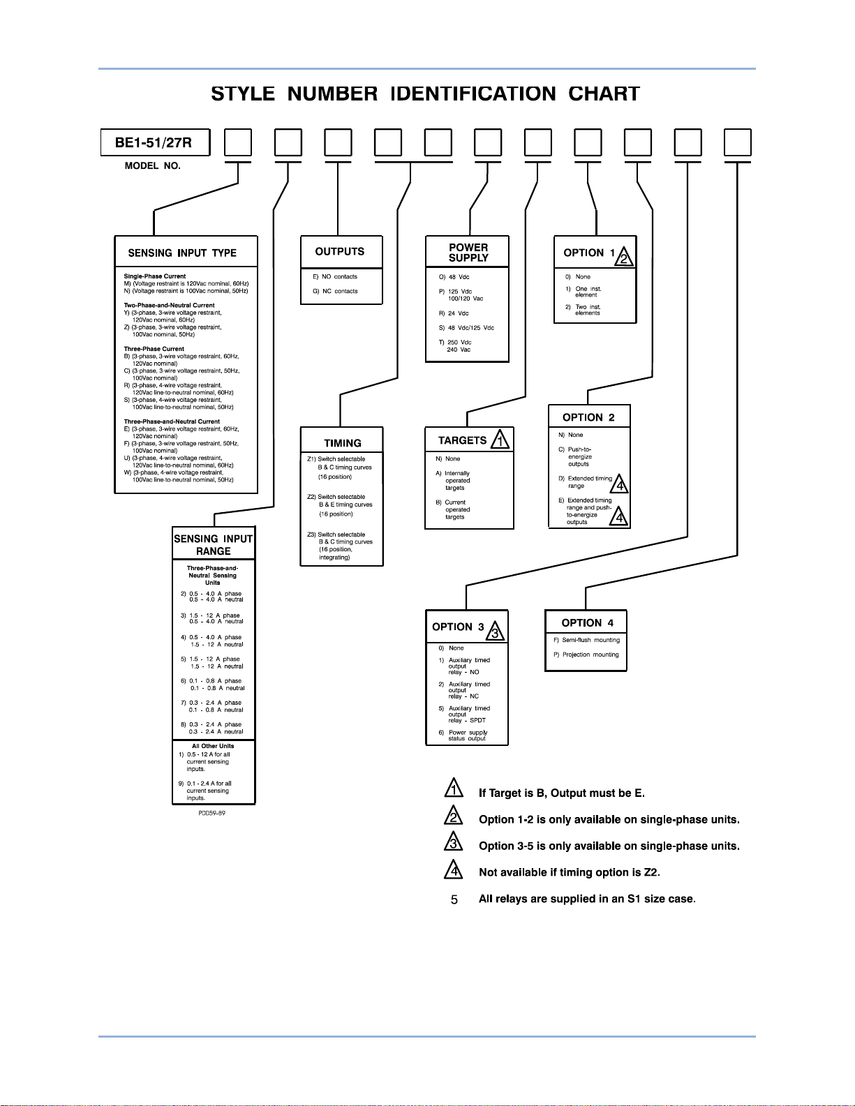
The Style Number Identification Chart (Figure 1) illustrates the manner in which the relay style number is
determined. For example, if the style number were U3E-Z1P-B1C1F, the device would have the following
characteristics:
U - Three-Phase-and-Neutral sensing, 3-p has e, 4-wire voltage restraint
3 - Sensing input range of 1.5 to 12.0 amperes for phase and 0.5 to 4.0 amperes for neutral
E - Normally open outputs
Z1 - Switch selectable time curves
P - Operating power derived from 125 Vdc or 120 Vac
B - Current operated targets
1 - One instantaneous element
C - Push-to-energize outputs
1 - Normally open auxiliary timed output relay
F - Semi-flush mounting
BE1-51/27R Introduction
Page 14
8 9137200999 Rev F
Figure 1. Style Number Identification Chart
Introduction BE1-51/27R
Page 15
9137200999 Rev F 9
Controls and Indicators
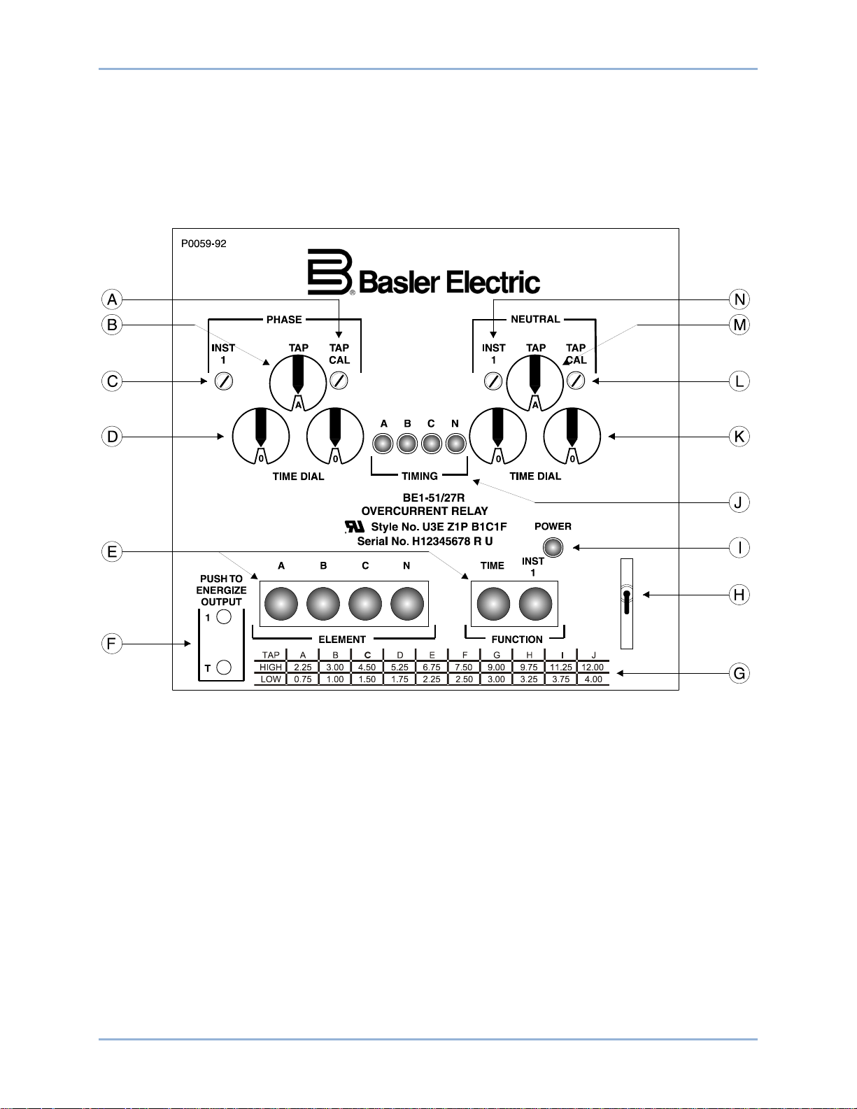
BE1-51/27R controls and indicators are located on the front panel and left-side interior. The controls and
indicators are shown in Figure 2 and described in Table 4. Your relay may not have all of the controls and
indicators shown and described here.
BE1-51/27R Controls and Indicators
Figure 2. Location of Controls and Indicators
Page 16

10 9137200999 Rev F
Table 4. Controls and Indicators
A Phase Tap Calibration Control. This single-turn potentiometer adjusts the phase overcurrent pickup
threshold between the selected phase tap setting and the next lower tap setting.
B Phase Tap Selector. Selects the phase overcurrent pickup point in conjunction with the front panel
Phase Tap Calibration Control (locator A).
C Phase Instantaneous 1 Control. This four-turn potentiometer adjusts the phase instantaneous 1
element trip setting over the range of 1 to 40 times the selected Phase Tap Selector (locator B)
setting value. Your relay may be equipped with a Phase Instantaneous 2 Control which provides
similar adjustment of the phase instantaneous 2 element trip setting.
D Phase Time Dial Selector. These two knobs set the time delay between sensing of a phase
overcurrent condition and closing of the output contacts. See the Time Overcurrent Characteristic
Curves chapter for curve selection information.
E Target Indicators. LED indicators latch on when the corresponding output relay is energized by an
overcurrent condition. Target indicators are reset by the Target Reset Switch (locator H).
F Push-to-Energize Output Pushbuttons. These recessed pushbuttons are depressed to energize the
external trip circuits for testing purposes. A thin, non-conducting rod should be used to depress the
buttons. Do not use a screwdriver.
G Tap Selector Table. This front-panel reference lists the high and low setting limits for a particular tap
selection.
H Target Reset Switch. Operating this switch resets all active targets (locator E).
I Power Ind ic ator. This LED indicator lights when control power is applied and the relay power supply is
functioning.
J Timing Indicators. A Timing LED lights when the corresponding overcurrent pickup point is reached
and exceeded.
K Neutral Time Dial Selector. These two knobs set the time delay between sensing of a neutral
overcurrent condition and closing of the output contacts. See the Time Overcurrent Characteristic
Curves chapter for curve selection information.
L Neutral Tap Calibration Control. This single-turn potentiometer adjus ts the phase over c urr ent pickup
threshold between the selected neutral tap setting and the next lower tap setting.
M Neutral Tap Selector. Selects the neutral overcurrent pickup point in conjunction with the front panel
Neutral Tap Calibration Control (locator L).
N Neutral Instantaneous 1 Control. This four-turn potentiometer adjusts the neutral instantaneous 1
element trip setting over the range of 1 to 40 times the selected Neutral Tap Selector (locator M)
setting value.
The time overcurrent characteristic curve selector (not shown) is located on the left-side interior. This
circuit board mounted switch selects the characteristic curve to be used.
Prior to August 2010, this switch was located behind the front panel.
The normal/test slide switch (not shown) is located on the left-side interior. This switch is only used for
factory testing and must be in the normal position (towards front of relay) for proper operation.
Prior to August 2010, this switch was located on the right-side interior.
The tap range plate (not shown) indicates the terminal connections (high or low) used to select the current
sensing input range. The sensing input ranges are listed in Table 5.
Controls and Indicators BE1-51/27R
Page 17

9137200999 Rev F 11
Table 5. Sensing Input Ranges
TAP
Range
Plate
or
Pickup
HIGH 2.25 3.00 4.50 5.25 6.75 7.50 9.00 9.75 11.25 12.00 8,7 — — —
LOW 0.75 1.00 1.50 1.75 2.25 2.50 3.00 3.25 3.75 4.00 9,7 — — —
HIGH 2.25 3.00 4.50 5.25 6.75 7.50 9.00 9.75 11.25 12.00 8,7 14,15 17,18 —
LOW 0.75 1.00 1.50 1.75 2.25 2.50 3.00 3.25 3.75 4.00 9,7 13,15 16,18 —
HIGH 2.25 3.00 4.50 5.25 6.75 7.50 9.00 9.75 11.25 12.00 8,7 — 14,15 17,18
LOW 0.75 1.00 1.50 1.75 2.25 2.50 3.00 3.25 3.75 4.00 9,7 — 13,15 16,18
Phase
or
Neutral
Phase 2.25 3.00 4.50 5.25 6.75 7.50 9.00 9.75 11.25 12.00 8,9 13,14 15,16 —
Neutral 0.75 1.00 1.50 1.75 2.25 2.50 3.00 3.25 3.75 4.00 — — — 17,18
A B C D E F G H I J ØA ØB ØC N
Sensing Input Range 1, Two-Phase-and-Neutral *
Sensing Input Range 2, Three-Phase-and-Neutral
0.75 1.00 1.50 1.75 2.25 2.50 3.00 3.25 3.75 4.00 8,9 13,14 15,16 17,18
Sensing Input Range 3, Three-Phase-and-Neutral
TAP Selector
Sensing Input Range 1, Single-Phase *
Sensing Input Range 1, Three-Phase *
Current Sensing
Terminals
Sensing Input Range 4, Three-Phase-and-Neutral
Phase 0.75 1.00 1.50 1.75 2.25 2.50 3.00 3.25 3.75 4.00 8,9 13,14 15,16 —
Neutral 2.25 3.00 4.50 5.25 6.75 7.50 9.00 9.75 11.25 12.00 — — — 17,18
Sensing Input Range 5, Three-Phase-and-Neutral
Phase or
Neutral
Phase or
Neutral
Phase 0.45 0.60 0.90 1.05 1.35 1.50 1.80 1.95 2.25 2.40 8,9 13,14 15,16 —
Neutral 0.15 0.20 0.30 0.35 0.45 0.50 0.60 0.65 0.75 0.80 — — — 17,18
Phase or
Neutral
HIGH 0.45 0.60 0.90 1.05 1.35 1.50 1.80 1.95 2.25 2.40 Same as Range 1
LOW 0.15 0.20 0.30 0.35 0.45 0.50 0.60 0.65 0.75 0.80 Same as Range 1
2.25 3.00 4.50 5.25 6.75 7.50 9.00 9.75 11.25 12.00 8,9 13,14 15,16 17,18
Sensing Input Range 6, Three-Phase-and-Neutral
0.15 0.20 0.30 0.35 0.45 0.50 0.60 0.65 0.75 0.80 8,9 13,14 15,16 17,18
Sensing Input Range 7, Three-Phase-and-Neutral
Sensing Input Range 8, Three-Phase-and-Neutral
0.45 0.60 0.90 1.05 1.35 1.50 1.80 1.95 2.25 2.40 8,9 13,14 15,16 17,18
Sensing Input Range 9 (All Other Sensing Types) *
* For relays with sensing input ranges 1 or 9, connect the system wiring to the current sensing terminals
for the desired range (HIGH or LOW).
BE1-51/27R Controls and Indicators
Page 18

12 9137200999 Rev F
Refer to Table 6 for target installation configurations.
Table 6. Target Installation Configurations
Number of Instantaneous Elements Targets Installed (Types A and B)
Sensing
Input Type
None One Two
X X
Element Function
A B C N TIME INST 1 INST 2
M, N
R, S
U, W
B, C
E, F
Y, Z
X X X
X X X X
X X X X
X X X X X X
X X X X X
X X X X X X X
X X X X
X X X X X X
X X X X X
X X X X X X X
X X X X
X X X X X X
Controls and Indicators BE1-51/27R
Page 19
9137200999 Rev F 13
Functional Description
BE1-51/27R Time Overcurrent Relays are microprocessor-based devices that provide voltage restraint of
the phase time overcurrent functions.
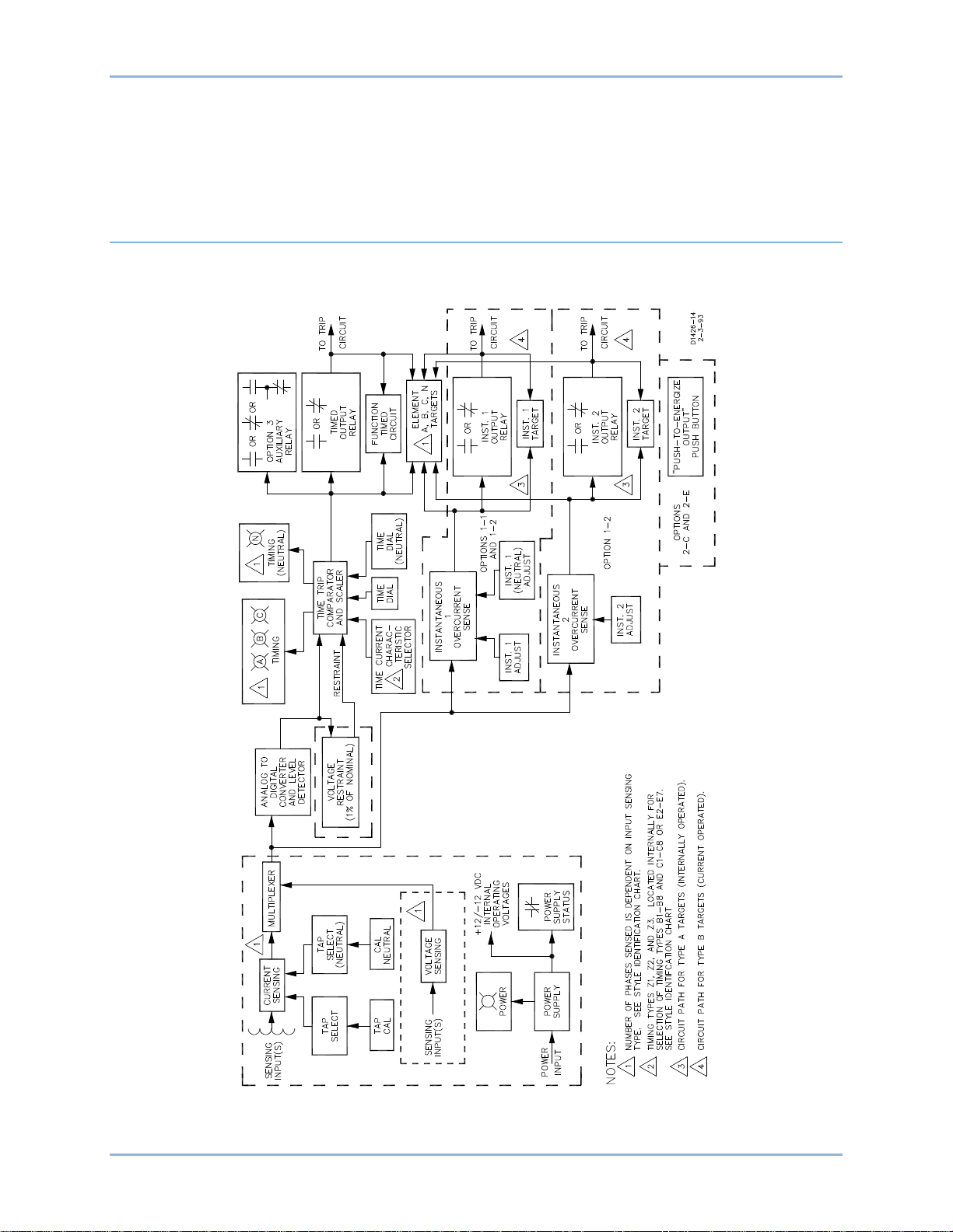
Block Diagram Analysis
The following block diagram analysis is referenced to Figure 3. A microprocessor (not illustrated in Figure
3) processes signals, performs logic functions, and all of the time overcurrent computations.
Figure 3. Functional Block Diagram
BE1-51/27R Functional Description
Page 20

14 9137200999 Rev F
Power Supply
Operating power for the relay circuitry is supplied by a wide range, electrically isolated, low-burden power
supply. Power supply operating power is not polarity sensitive. The front panel power LED and power
supply status output indicate when the power supply is operating. Power supply specifications are listed in
the Specifications chapter.
Current Sensing
All relay models (except three-phase-and-neutral units) have two sensing ranges for each phase. Each
high/low sensing range has its own set of input terminal connections.
• Five ampere CTs have: LOW (0.5 A to 4.0 A) and HIGH (1.5 A to 12.0 A).
• One ampere CTs have: LOW (0.1 A to 0.8 A) and HIGH (0.3 A to 2.4 A).
Three-phase-and-neutral sensing units, however, have one of four possible combinations of input sensing
ranges with one range for neutral and one range for the phases.
• Five ampere CTs have: 0.5 A to 4.0 A and 1.5 A to 12.0 A.
• One ampere CTs have: 0.1 A to 0.8 A and 0.3 A to 2.4 A.
Tap Select and Tap Cal
Front panel TAP selectors and TAP CAL controls are provided for selection and precise adjustment of
the phase and neutral (if provided) time overcurrent pickup points. The front panel TAP selectors, tenposition BCD weighted rotary switches, select the desired current sensing pickup point, while the front
panel TAP CAL controls provide precise adjustment between the selected setting and the next lower
setting.
Voltage Sensing
Input voltage for each phase to be monitored is applied to the voltage sensing circuits. Each voltage
sensing circuit consists of an input transformer, rectifier, and filter Analog voltages from the voltage
sensing circuits are applied to the multiplexor. Note that neutral is not monitored for voltage.
Multiplexor
The multiplexor sequentially switches a voltage representing each of the sensed input currents to the
analog-to-digital converter and level detector.
Analog-To-Digital Converter and Level Detector
When the voltage representing the actual sensed inputs meets or exceeds the selected pickup point, this
circuit converts the level to a corresponding binary number and applies it to a time trip comparator and
scaler circuit and to a counter for calculation of the required time delay.
Time Trip Comparator and Scaler
This circuit accepts both the binary number representing the detected current level and the desired time
delay characteristic selected by the front panel TIME DIAL, then computes the required time delay before
the timed output relay will be energized. Time delay characteristics are shown in the curves located in the
Time Overcurrent Characteristic Curves chapter. If extended timing range options 2-D or 2-E is present,
the time delay characteristic curves are modified so that the time delay is approximately 5.7 times the
derived value.
Time delay computations are updated continuously so that changes in the overcurrent condition are
monitored and result in a corresponding change in the time delay. A software counter begins counting
when the initial binary number is received from the analog-to-digital converter and level detector. The
counter measures the elapsed time of the overcurrent condition, and resets if the current decreases
below the pickup point. This continuously increasing binary number is then passed to the comparator.
Functional Description BE1-51/27R
Page 21

9137200999 Rev F 15
V
V
I
I
M
N
t
×=
Voltage Restraint
Voltage restraint compares the binary number representing the monitored voltage with the fixed nominal
voltage limit (100 Vac for 50-hertz systems and 120 Vac for 60-hertz systems). When the voltage is
between 100 percent and 25 percent of the nominal voltage, the circuit automatically lowers the selected
time overcurrent pickup point proportionally. Instantaneous overcurrent operation, if present, is not
affected. Neutral is not monitored for voltage, nor is the neutral time overcurrent pickup point restrained.
When the voltage is above the 100 percent limit, the pickup point is restrained to 100 percent. When the
voltage is below the 25 percent limit, the pickup point remains at the 25 percent point.
For a given level of current above pickup, a lowering of the pickup point, via voltage restraint effectively
increases the multiples of current. This shifts the time delay characteristic to the right on the multiples-ofpickup-current axis (characteristic curves) as voltage drops from 100 percent to 25 percent.
To find the effective multiple of pickup current use the formula:
Where: M = Multiple of tap value current
I = Applied current level
I
V
= Tap value
T
= Nominal voltage
N
V = Applied voltage level
Microprocessor (Not Shown)
Some of the circuitry already discussed is part of the microprocessor and no definite lines are drawn to
separate the functions. The microprocessor compares the desired time delay (from the time trip
comparator and scaler) with the actual elapsed time from the counter. When the elapsed time reaches the
intended delay, the timed output relay is energized. During the time delay period, the front panel TIMING
indicator (i.e. pickup) associated with the detected phase is illuminated.
If targets are present, the front panel TIME FUNCTION target will be tripped, and the A, B, C, or N
ELEMENT target associated with the detected phase will be tripped. See the Controls and Indicators
chapter for the types of targets that are present (depending upon relay configuration).
If option 3 is present, an auxiliary output relay (with N.O., N.C., or SPDT contacts) is also actuated when
the timed output relay energizes.
Instantaneous Overcurrent (Options 1-1 and 1-2)
Input current levels applied to the time overcurrent circuitry are also passed to the instantaneous
overcurrent circuitry. These levels are compared to the setting of the front panel INST 1 adjust and the
front panel INST 1 (NEUTRAL) adjust (if present). If the input current level is above the setting, the output
driver energizes the instantaneous 1 output relay. If the instantaneous 2 option is present, the input level
is also compared with the setting of the front panel INST 2 adjust to energize the instantaneous 2 output
relay. Note that the current level settings for the instantaneous overcurrent element will always be from 1
to 40 times above the front panel TAP and TAP (NEUTRAL) settings of the time overcurrent element.
If target type A or B is present, the front panel INST 1 target and the front panel INST 2 targets are
tripped when their respective output relay is energized, along with the front panel A, B, C or N EL EM ENT
targets (if present) associated with the detected phases. (See the Controls and Indicators chapter for the
types of targets that can be present depending upon the relay configuration.)
Timed and Instantaneous Outputs
Each output signal (representing either time overcurrent or instantaneous overcurrent) from each
monitored phase (or neutral) is applied to the respective output driver. Each output driver supplies
operating current to energize the associated output relay. Either normally open (output type E) or normally
BE1-51/27R Functional Description
Page 22

16 9137200999 Rev F
Note
closed (output type G) contacts may be specified. (The contact configurations of all output relays for a
given model will be the same.)
Auxiliary Outputs
In addition to the output relays, an auxiliary relay, having the same or a different contact configuration,
may be specified. Both the output and the auxiliary relays will remain energized for the duration of the
overcurrent condition.
Push-to-Energize Pushbuttons
If either option 2-C or 2-E is present, each individual output relay can be directly energized for test
purposes by the actuation of a front panel PUSH-TO-ENERGIZE OUTPUT pushbutton. The pushbutton is
actuated by the insertion of a thin, non-conducting rod through an access hole in the front panel.
Power Supply Status Output (Option 3-6)
Power supply status output relays have a set of normally closed contacts that are energized open during
power-up. If either or both power supply output legs (+12 Vdc or −12 Vdc) fails, the power supply status
output relay is de-energized and the output contacts close. Shorting bars across the output contacts are
held open by the installed connection plug. When the relay is removed from service by removing the
connection plug, the shorting bars are closed.
Target Indicators
Target indicators are optional components selected when a relay is ordered. The electronically latched
and reset targets consist of red LED indicators located on the relay front panel. A latched target is reset
by operating the target reset switch on the front panel. If relay operating power is lost, any illuminated
(latched) targets are extinguished. When relay operating power is restored, the previously latched targets
are restored to their latched state.
A relay can be equipped with either internally operated targets or current operated targets.
Internally Operated Targets
The relay trip outputs are directly applied to drive the appropriate target indicator. Each ind ic at or is
illuminated regardless of the current level in the trip circuit.
Current Operated Targets
A current operated target is triggered by closure of the corresponding output contact and the presence of
at least 200 milliamperes of current flowing in the trip circuit.
Note that the front panel function targets (TIMED, INST 1, etc.) may be either internally or current
operated. Phase and neutral indicators are current operated only if the instantaneous options are not
included and if current operated targets are specified.
Prior to August 2007, BE1-51/27R target ind ic ators co ns isted of
magnetically latched, disc indicators. These mechanically latch ed
target indicators have been replaced by the electronically latched LED
targets in use today.
Functional Description BE1-51/27R
Page 23

9137200999 Rev F 17
Caution
Note
Installation
BE1-51/27R relays are shipped in sturdy cartons to prevent damage during transit. Upon receipt of a
relay, check the model and style number against the requisition and packing list to see that they agree.
Inspect the relay for shipping damage. If there is evidence of damage, file a claim with the carrier, and
notify your sales representative or Basler Electric.
If the relay will not be installed immediately, store it in its original shipping carton in a moisture- and dustfree environment. Before placing the relay in service, it is recommended that the test procedures of the
Tests and Adjustments chapter be performed.
Relay Operating Guidel ines and Precautions
Before installing or operating the relay, note the following guidelines and precautions:
• For proper current operated target operation, a minimum current of 200 milliamperes must flow
through the output trip circuit.
• If a wiring insulation test is required, remove the connection plugs and withdraw the relay from its
case.
When the connection plugs are removed, the relay is disconnected
from the operating circuit and will not provide system protection.
Always be sure that external operating (monitored) conditions are
stable before removing a relay for inspection, test, or service.
Be sure that the BE1-51/27R is hard-wired to earth ground with no
smaller than 12 AWG copper wire attached to the ground terminal on
the rear of the case. When the BE1-51/27R is configured in a system
with other devices, it is recommended to use a separate lead to the
ground bus from each device.
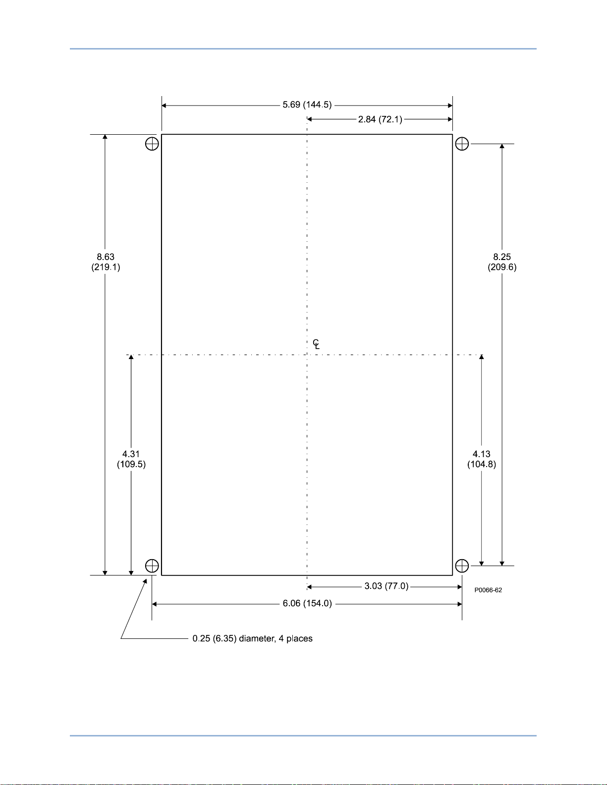
Mounting
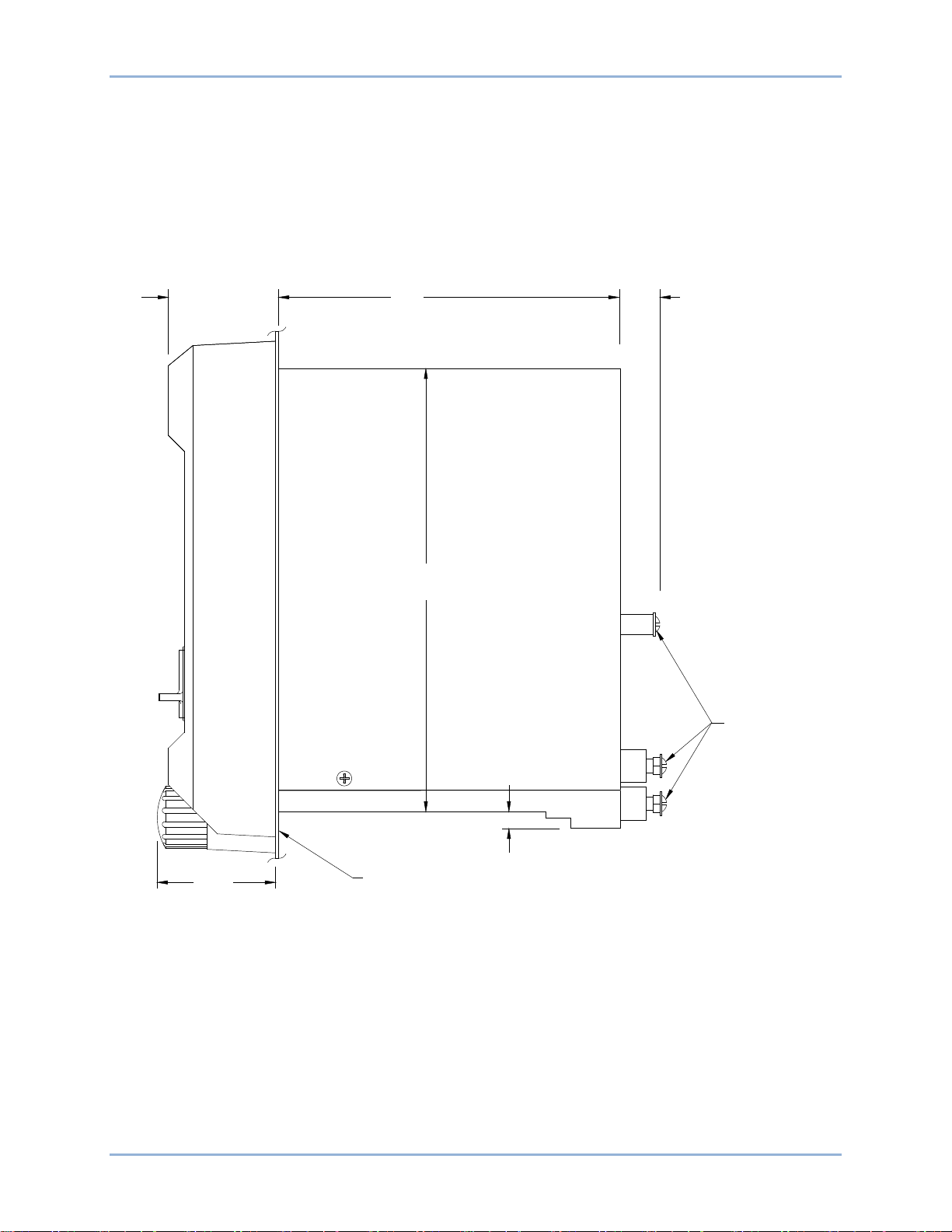
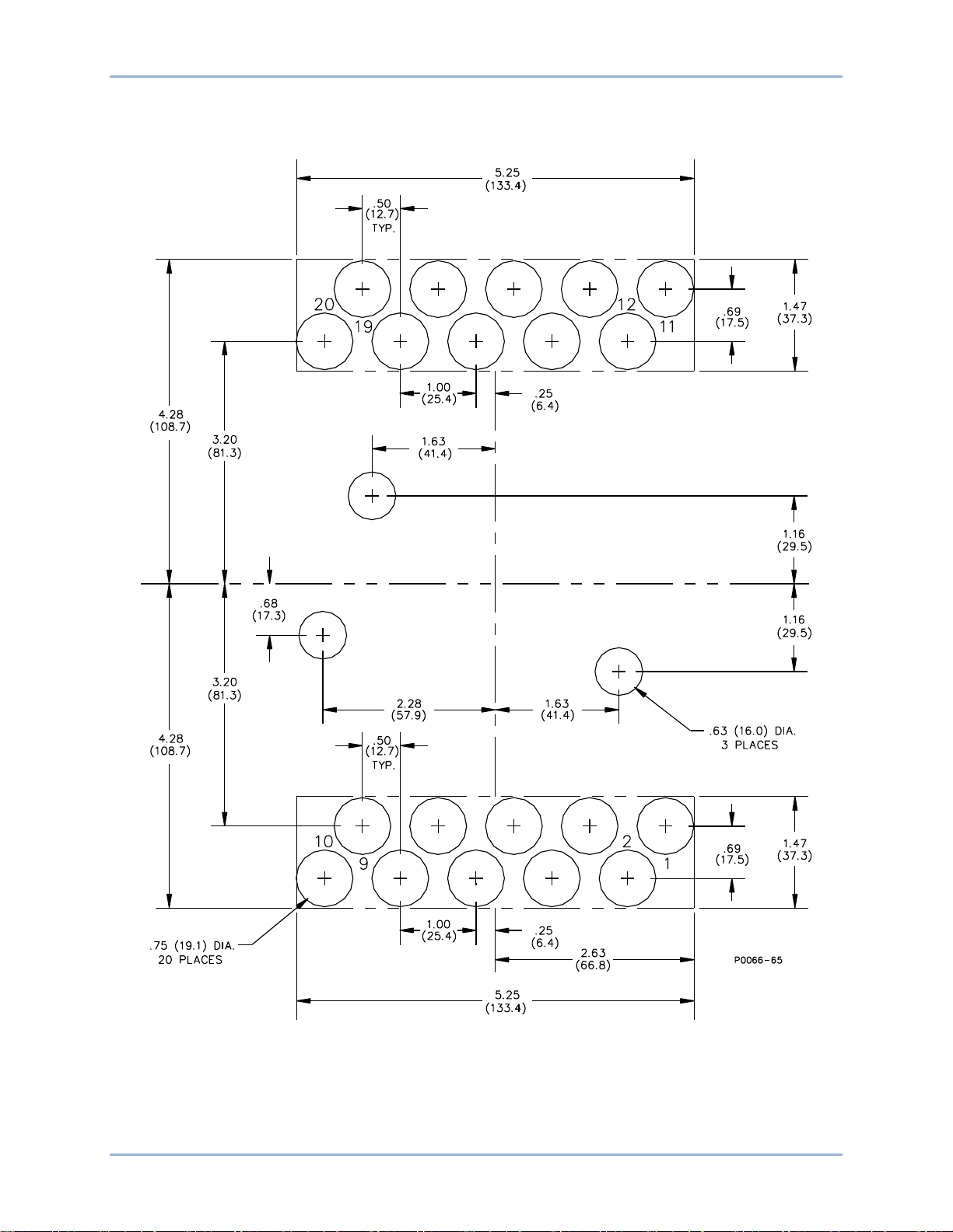
Because the relay is of solid-state design, it does not have to be mounted vertically. Any convenient
mounting angle may be chosen. Refer to the following figures for relay outline dimensions and panel
drilling diagrams.
BE1-51/27R Installation
Page 24
18 9137200999 Rev F
Figure 4. Panel Cutting/Drilling, Semi-Flush, S1 Case
Installation BE1-51/27R
Page 25
9137200999 Rev F 19
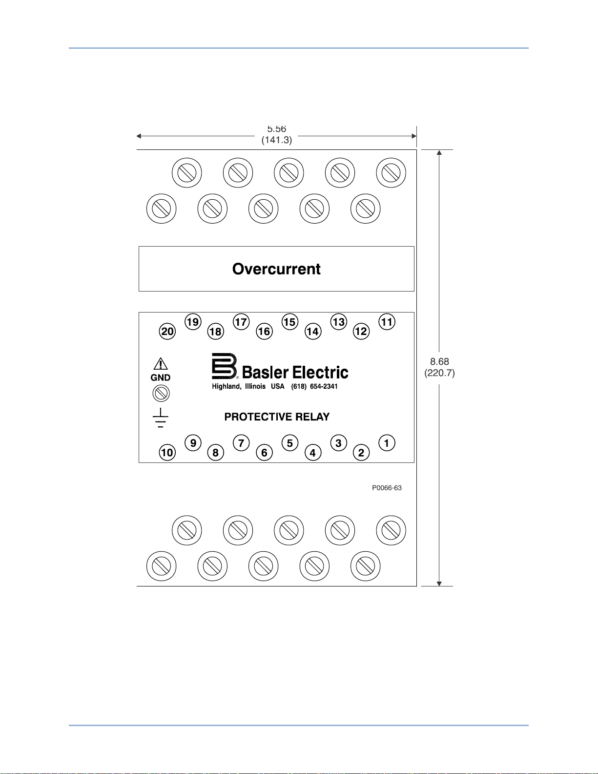
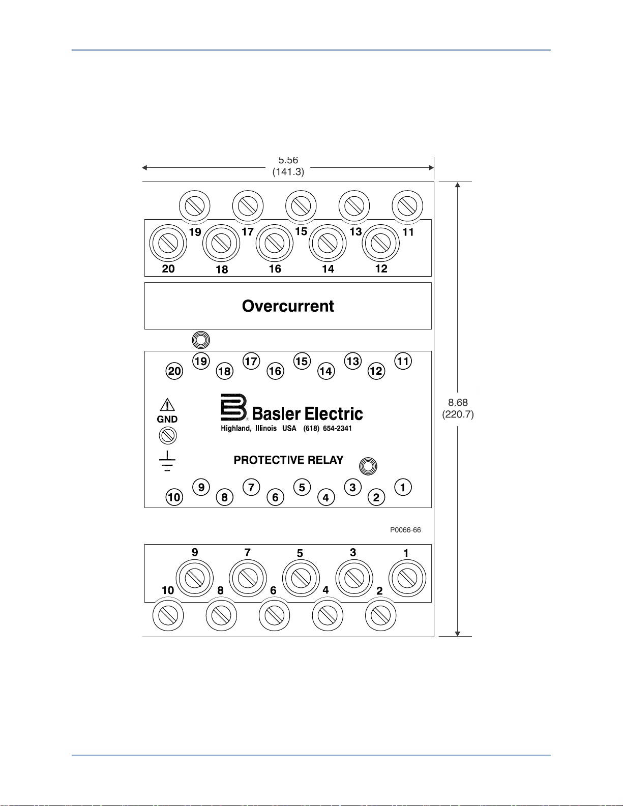
Figure 5. S1 Case Dimensions, Rear View, Double Ended, Semi-Flush Mount
BE1-51/27R Installation
Page 26
20 9137200999 Rev F
.75
(19.1)(157.2)
6.19
(49.53)
1.95
10-32 SCREWS
(7.9)
.31
10-32 SCREWS
(102.4)
4.03
4.03
(102.4)
(
7.9)
.31
MOUNTING PANEL
(55.75
)
2.195
P0066-64
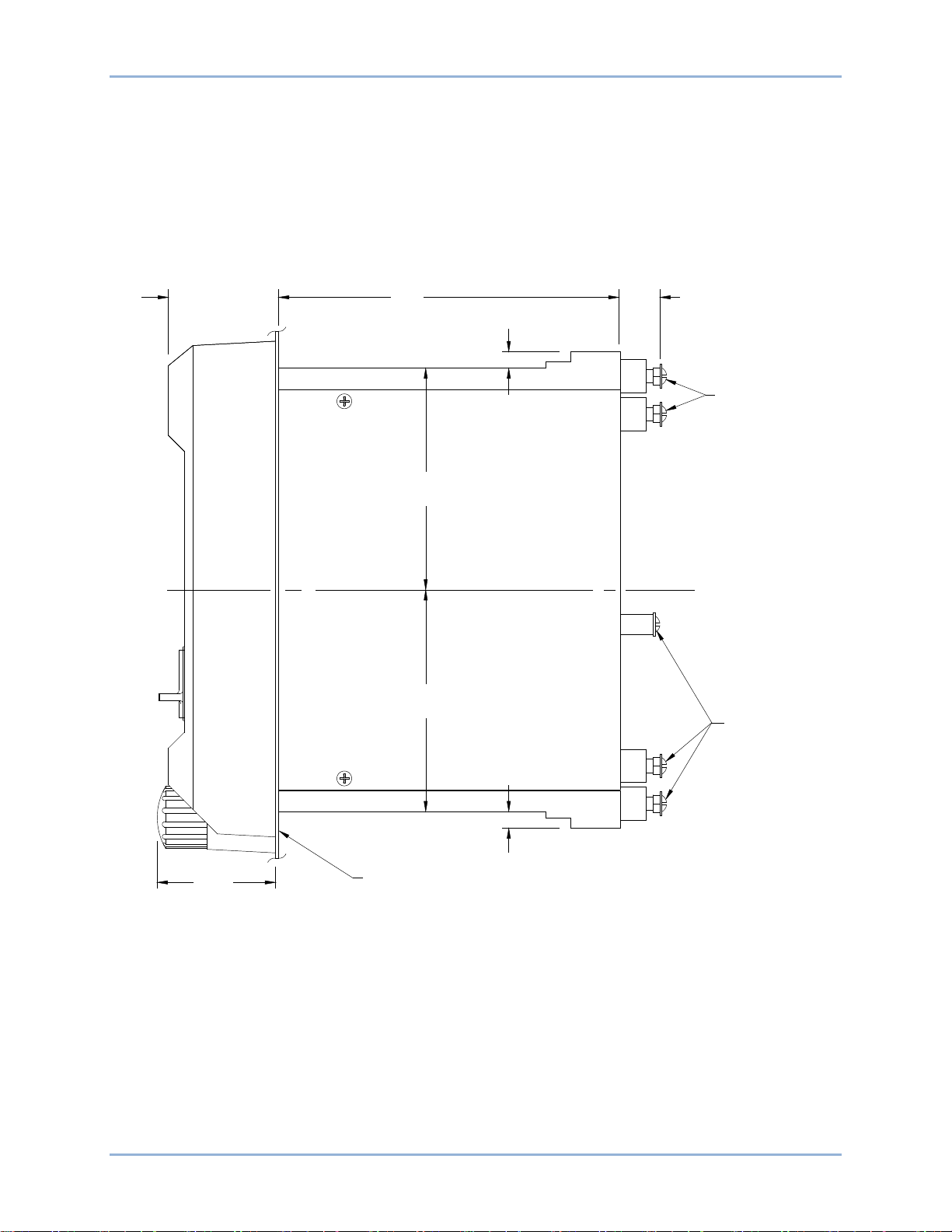
Figure 6. S1 Case Dimensions, Side View, Double Ended, Semi-Flush Mount
Installation BE1-51/27R
Page 27
9137200999 Rev F 21
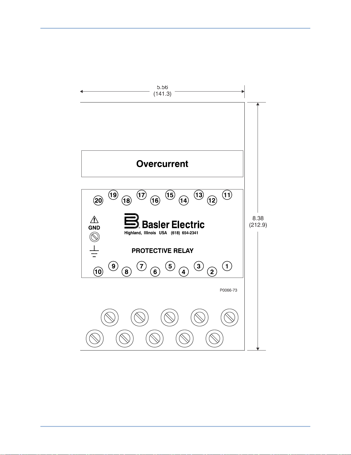
Figure 7. S1 Case Dimensions, Rear View, Single Ended, Semi-Flush Mount
BE1-51/27R Installation
Page 28
22 9137200999 Rev F
.75
(19.1)(157.2)
6.19
(49.53)
1.95
10-32 SCREWS
MOUNTING PANEL
(55.75)
2.195
P0066-69
8.06
(204.72)
(7.9)
.31
Figure 8. S1 Case Dimensions, Side View, Single Ended, Semi-Flush Mount
Installation BE1-51/27R
Page 29
9137200999 Rev F 23
Figure 9. Panel Cutting/Drilling, Double Ended, Projection Mount, S1 Case
BE1-51/27R Installation
Page 30
24 9137200999 Rev F
Figure 10. S1 Case Dimensions, Rear View, Double Ended, Projection Mount
Installation BE1-51/27R
Page 31

9137200999 Rev F 25
.
75
(
19
.1
)
(
157.
2)
6.
19
(
49
.53
)
1
.
95
10-
32 SCREWS
(
7.
9
)
.
31
10
-32 SCREWS
(
102.4)
4.
03
4.03
(102.
4)
(7.
9)
.
31
(55
.75
)
2.
195
P0066-
67
TERMINAL EXTENSION
(TYP.)
FOR DETAILED INSTRUCITONS,
SEE THE TERMINAL PROJECTION
MOUNTING KIT SUPPLIED.
.25
(6.
4)
5
/16-
18
STUD
2
PLACES
MOUNTING PANEL
Figure 11. S1 Case Dimensions, Side View, Double Ended, Projection Mount
BE1-51/27R Installation
Page 32

26 9137200999 Rev F
Figure 12. Panel Cutting/Drilling, Single Ended, Projection Mount, S1 Case
Installation BE1-51/27R
Page 33

9137200999 Rev F 27
Figure 13. S1 Case Dimensions, Rear View, Single Ended, Projection Mount
BE1-51/27R Installation
Page 34

28 9137200999 Rev F
(157.2)
6.19
(49.53)
1.95
10-32 SCREWS
MOUNTING PANEL
(55.75)
2.195
P0066-71
TERMINAL EXTENSION (TYP.)
FOR DETAILED INSTRUCITONS,
SEE THE TERMINAL PROJECTION
MOUNTING KIT SUPPLIED.
.25
(6.4)
5/16-18 STUD
2 PLACES
MOUNTING PANEL
8.06
(204.72)
(7.9)
.31
.75
(19.1)
Figure 14. S1 Case Dimensions, Side View, Single Ended, Projection Mount
Installation BE1-51/27R
Page 35

9137200999 Rev F 29
P
0066-68
Figure 15. S1 Case Cover Dimensions, Front View
BE1-51/27R Installation
Page 36

30 9137200999 Rev F
P
0050-03
Connections
Be sure to check the model and style number of a relay before connecting and energizing the relay.
Incorrect wiring may result in damage to the relay. Except where noted, connections should be made with
wire no smaller than 14 AWG.
Typical external and internal connections are shown in the following figures.
To prevent an inductive overload of the relay contacts, it is necessary to break the trip circ uit ex t er nally
through the 52a contacts.
Relay circuitry is connected to the case terminals by removable connection plugs (1 plug for 10-terminal
cases and 2 plugs for 20-terminal cases). Removal of the connection plug(s) opens the normally open trip
contact circuits and shorts the normally closed trip circuits before opening the power and sensing circuits.
Figure 16. Typical External Connections, Current Operated Targets, DC Powered
Installation BE1-51/27R
Page 37

9137200999 Rev F 31
P
0050-0
4
P0050-05
Figure 17. Typical Sensing External Connections, Sensing Input Type M or N
Figure 18. Typical Sensing External Connections, Sensing Input Type R or S
BE1-51/27R Installation
Page 38

32 9137200999 Rev F
P005
0-06
P0050-07
Figure 19. Typical Sensing External Connections, Sensing Input Type U or W
Figure 20. Typical External Connections, Sensing Input Type B or C
Installation BE1-51/27R
Page 39

9137200999 Rev F 33
P005
0-08
P0050-09
Figure 21. Typical Sensing External Connections, Sensing Input Type E or F
Figure 22. Typical Sensing External Connections, Sensing Input Type Y or Z
BE1-51/27R Installation
Page 40

34 9137200999 Rev F
Figure 23. Typical Internal Diagram, Sensing Input Type M or N
Installation BE1-51/27R
Page 41

9137200999 Rev F 35
Figure 24. Typical Internal Diagram, Sensing Input Type Y or Z
BE1-51/27R Installation
Page 42

36 9137200999 Rev F
Figure 25. Typical Internal Diagram, Sensing Input Type B or C
Installation BE1-51/27R
Page 43

9137200999 Rev F 37
Figure 26. Typical Internal Diagram, Sensing Input Type R or S
BE1-51/27R Installation
Page 44

38 9137200999 Rev F
Figure 27. Typical Internal Diagram, Sensing Input Type E or F
Installation BE1-51/27R
Page 45

9137200999 Rev F 39
Figure 28. Typical Internal Diagram, Sensing Input Type U or W
BE1-51/27R Installation
Page 46

40 9137200999 Rev F
Maintenance
BE1-51/27R relays require no preventative maintenance other than a periodic operational check. If the
relay fails to function properly, contact Technical Sales Support at Basler Electric to coordinate repairs.
Storage
This device contains long-life aluminum electrolytic capacitors. For devices that are not in service (spares
in storage), the life of these capacitors can be maximized by energizing the device for 30 minutes once
per year.
Installation BE1-51/27R
Page 47

9137200999 Rev F 41
Note
Note
Tests and Adjustments
Procedures in this section are for use in testing and adjusting a relay for the desired operation in a
protective scheme. If a relay fails an operational test, or if an adjustment discloses a faulty relay, contact
Basler Electric.
Required Test Equipment
Minimum test equipment required for relay testing and adjustment is listed below. Refer to the following
figures for test setups.
• Appropriate ac or dc power source for relay operation
• Appropriate ac source (50- or 60-hertz as appro pr iat e) for volta ge and current testing
• Dc external power source for output relay(s) test setup and timer input
• Relay test set capable of delivering 40 amperes. A higher capability is needed for instantaneous
settings above 40 amperes
• Timer
• One shunt resistor for providing minimum target load
Operational Test
Preliminary Instructions
Perform the following steps before going on to any testing.
Step 1. Connect the relay test setup in accordance with Figures 29 through 34, depending upon the
sensing input type for your relay (see the style chart in the General Information chapter).
(a) Sensing Input Type M or N (Single-Phase Sensing). Refer to Figure 29
For relays having the above sensing, only the from panel LOW range
current sense terminal(s) should be connected for a complete check of
the relay.
Ensure that timed output termina ls 1 and 10 are conn e cted.
(b) Sensing Input Type R or S (Three-Phase Sensing). Refer to Figure 30
For relays having the above sensing, only the from panel LOW range
current sense terminal(s) should be connected for a complete check of
the relay.
.
.
For all three-phase relays, the test signals must connect to both the
current and voltage terminals for the same phase.
BE1-51/27R Tests and Adjustments
Ensure that timed output termina ls 1 and 10 are conne c ted.
Page 48

42 9137200999 Rev F
(c) Sensing Input Type U or W (Three-Phase with Neutral Sensing). Refer to Figure 31.
Ensure that the timed output terminals 1 and 10 are connected. Also, verify that either A,
B, or C current sense terminals are connected initially (N terminals will be connected later
in the test).
(d) Sensing Input Type B or C (Three-Phase Sensing). Refer to Figure 32
.
Ensure that the timed output terminals 1 and 10 are connected. Also, verify that either A,
B, or C current sense terminals are connected initially (N terminals will be connected later
in the test). Ensure that the voltage sense terminals and the current sense terminals are
connected to the same phase.
(e) Sensing Input Type E or F (Three-Phase with Neutral Sensing). Refer to Figure 33
.
Ensure that the timed output terminals 1 and 10 are connected. Also, verify that either A,
B, or C current sense terminals are connected initially (N terminals will be connected later
in the test).
(f) Sensing Input Type Y or Z (Two-Phase with Neutral Sensing). Refer to Figure 34
.
Ensure that the timed output terminals 1 and 10 are connected. Also, verify that either A,
B, or C current sense terminals are connected initially (N terminals will be connected later
in the test).
Step 2. Remove the relay front cover.
Step 3. Set the front panel TIME DIAL selector and, if present, the front panel TIME DIAL (NEUTRAL)
selector to 99.
Step 4. Adjust the front panel INST 1 and INST 2 controls, if present, fully clockwise (CW).
Step 5. Adjust the front panel TAP CAL control, and if present, the front panel TAP (NEUTRAL) control
fully CW.
Step 6. Ensure that the relay front panel TARGETS, if present, are reset.
Step 7. Apply 100% of nominal voltage based on the sensing input type for your relay.
Figure 29. Test Setup for Sensing Input Type M or N (Single-Phase Sensing)
Tests and Adjustments BE1-51/27R
Page 49

9137200999 Rev F 43
Figure 30. Test Setup for Sensing Input Type R or S (Three-Phase Sensing)
Figure 31. Test Setup for Sensing Input Type U or W (Three-Phase with Neutral Sensing)
BE1-51/27R Tests and Adjustments
Page 50

44 9137200999 Rev F
Figure 32. Test Setup for Sensing Input Type B or C (Three-Phase, Delta Configuration)
Figure 33. Test Setup for Sensing Input Type E or F (Three-Phase with Neutral Sensing)
Tests and Adjustments BE1-51/27R
Page 51

9137200999 Rev F 45
Note
Figure 34. Test Setup for Sensing Input Type Y or Z (Two-Phase with Neutral Sensing)
Time Overcurrent Pickup Test
This test checks the minimum and maximum overcurrent pickup points of the time overcurrent element.
During this test, disregard any indication on the test setup timer.
Step 1. Perform the preliminary instructions.
Step 2. Set the front panel TAP selector to A.
Step 3. Adjust the test set, for an overcurrent threshold having one of the following values:
(a) 0.5 for relays with Sensing Input Range 1, 2, or 4.
(b) 1.5 A for relays with Sensing Input Range 3 or 5.
Step 4. Slowly adjust the front panel TAP CAL control CCW until the front panel TIMING indicator
illuminates.
RESULT: For the phase minimum overcurrent pickup point of 0.5 A (Step 3a, above) or 1.5 A
(Step 3b, above) the front panel TAP CAL control should be near its maximum CCW limit.
Step 5. Adjust the front panel TAP CAL control fully CW to allow measurement of the actual
overcurrent pickup point at the A setting of the front panel TAP selector. Note that the front
panel TIMING indicator wil l exting uis h. Do not disturb t his sett ing.
Step 6. Slowly increase the current toward the value of the front panel TAP selector A setting until the
front panel TIMING indicator illuminates. Do not disturb this setting.
Step 7. Record the current reading and remove input current.
RESULT: The recorded value should be within ±5% of the front panel TAP selector A setting
for the phase minimum overcurrent pickup point for the time overcurrent.
BE1-51/27R Tests and Adjustments
Page 52

46 9137200999 Rev F
Note
Step 8. Set the front panel TAP selector to J.
Step 9. Slowly adjust the test set, increasing the overcurrent threshold toward the value of the front
panel TAP selector J setting until the front panel TIMING indicator just illuminates. Do not
disturb this setting.
Step 10. Record the current reading and remove input current.
RESULT: The recorded value should be within ±5% of the front panel TAP selector J setting for
the phase maximum overcurrent pickup point for the time overcurrent element.
Step 11. Perform the following steps as appropriate for the correct sensing input types.
Ensure that the voltage sense terminals and current sense terminals
are connected to the same phase.
(a) Sensing Input Type M or N (Single-Phase Sensing). This concludes the time overcurrent
test. Proceed to the timed output test.
(b) Sensing Input Type Y or Z (Two-Phase and Neutral Sensing). Remove the power and
reconnect the input sensing to the remaining phases as shown in Figure 34, eac h time
repeating Steps 1 through 10. For neutral testing, continue with Step 12.
(c) Sensing Input Type B, C, R, or S (Three-Phase Sensing). Remove the power and
reconnect the input sensing to each of the remaining phases as shown in Figures 32 and
34, each time repeating Steps 1 through 10.
(d) Sensing Input Type E, F, U, or W (Three-Phase with Neutral Sensing). Remove the
power and reconnect the input sensing to each of the remaining phases as shown in
Figures
with Step 12.
Step 12. Perform the preliminary instructions.
For the neutral sensing (terminals 17 and 18), connect the relay as shown in Figures 31 and 33,
then perform the following steps (Steps 13 through 21).
Step 13. Set the front panel TAP (NEUTRAL) selector to A.
Step 14. Adjust the test set for an overcurrent threshold having one of the following values:
(a) 0.5 A for relays with Sensing Input Range 2 or 3.
(b) 1.5 A for relays with Sensing Input Range 4 or 5.
Step 15. Slowly adjust the front panel CAL (NEUTRAL) control CCW until the front pan el TIMING
indicator illuminates.
RESULT: For the neutral minimum overcurrent pickup point of 0.5 A (Step 16a, above) or 1.5 A
(Step 16b, above) the front panel CAL (NEUTRAL) control should be near its maximum CCW
limit.
Step 16. Adjust the front panel CAL (NEUTRAL) control fully CW to allow measurement of the actual
overcurrent pickup point at the A setting of the front panel TAP (NEUTRAL) selector. Note that
the front panel TIMING (NEUTRAL) indicator will extinguish. Do not disturb this set ti ng.
31 and 33, each time repeating Steps 1 through 10. For neutral testing, continue
Step 17. Slowly increase the current toward the value of the front panel TAP (NEUTRAL) selector A
setting until the front panel TIMING (NEUTRAL) indicator illuminates. Do not disturb this
setting.
Step 18. Record the current reading and remove input current.
Tests and Adjustments BE1-51/27R
Page 53

9137200999 Rev F 47
Note
Note
RESULT: The recorded value should be within ±5% of the front panel TAP (NEUTRAL)
selector A setting for the neutral minimum overcurrent pickup point for the time overcurrent.
Step 19. Set the front panel TAP (NEUTRAL) selector to J.
Step 20. Slowly adjust the test set, increasing the overcurrent threshold toward the value of the front
panel TAP (NEUTRAL) selector J setting until the front panel TIMING (NEUTRAL) indicator
just illuminates. Do not disturb this setting.
Step 21. Record the current reading and remove input current.
RESULT: The recorded value should be within ±5% of the front panel TAP (NEUTRAL)
selector J setting for the neutral maximum overcurrent pickup point for the time overcurrent
element.
Timed Output Test
This test checks the accuracy of the time overcurrent characteristic delay.
For relays having three-phase sensing (Sensing Input Type B, C, R, or
S) only a single input phase needs to be connected, since this is
sufficient for a complete test of the Time Delay. For relays that include
neutral sensing (Sensing Input Type E, F, U, N, Y, or Z), this test
includes reconnecting the Test Output to the Neutral Sensin g
terminals for testing the Timed Output during neutral sensing.
Step 1. Verify that the preliminary instructions have been performed.
Step 2. (Timing type Z1, Z2, or Z3 only.) Select the desired time current characteristic curve.
Step 3. Set the front panel TAP selector to B.
Step 4. Adjust the front panel TIME DIAL to 20.
Step 5. Adjust the test set for an overcurrent threshold of precisely 5 times the front panel TAP selector
B setting.
Step 6. Apply input current to the relay and initiate the test setup timer.
Step 7. Observe that the appropriate front panel TIMING indicator illuminates and when the time delay
ends that the timed output relay is energized.
RESULTS: (1) The appropriate front panel TIMING indicator extinguis hes.
(2) The test setup timer stops. (Record count for use in Step 9.)
(3) If target type A or B is present:
(a) The front panel FUNCTION-TIME target (if present) trips.
(b) The appropriate front panel ELEMENT target A, B, or C (if present)
trips.
Step 8. Remove input current and (if present) reset the relay front panel targets.
Due to delays inherent in the test equipment, the time delay for the
following test may appear to exceed these limits.
BE1-51/27R Tests and Adjustments
Page 54

48 9137200999 Rev F
Note
Step 9. On the appropriate time overcurrent curve chart (in the Time Overcurrent Characteristic Curves
chapter), locate the line representing 5 times the tap value (from Step 5) where it intersects the
particular curve representing the front panel TIME DIAL setting of 20 (from Step 4). The
resulting time delay value in seconds should be within ±5% of the timer reading [from Step
7(2)].
Step 10. Adjust the front panel TIME DIAL to 40, 60, and 99, each time repeating Steps 6 through 9.
For relays having two-phase-and-neutral, three-phase, or three-phaseand-neutral sensing (Sensing Input Types B, C, E, F, R, S, U, W, Y, or
Z) it is not necessary to repeat this test for the remaining phases.
For relays having two-phase-and-neutral, or three-phase-and-neutral
sensing (Sensing Input Types E, F, U, W, Y, or Z) perform Steps 11
through 20.
For relays having single-phase or three-phase sensing (Sensing Input
Types B, C, M, N, R, or S) with insta nta neous overcurrent option 1-1
or 1-2, proceed to the instantaneous overcurrent test.
Step 11. Remove the power and reconnect the test output to the neutral current sensing input of the
relay as shown in Figures 31 and 33 (terminals 17 and 18).
Step 12. Set the front panel TAP (NEUTRAL) selector to B.
Step 13. Rotate the front panel CAL (NEUTRAL) control fully CW.
Step 14. Rotate the front panel TIME DIAL (NEUTRAL) to 20.
Step 15. Ensure that all relay targets have been reset.
Step 16. Adjust the test set for an overcurrent threshold of precisely 5 times the front panel TAP
(NEUTRAL) selector B setting as meas ur ed by the ammet er.
Step 17. Apply input current to the relay and initiate the test setup timer.
RESULTS: Observe that the appropriate front panel TIMING (NEUTRAL) indicator illuminates.
Step 18. When the time delay ends, the timed output relay is energized.
RESULTS: (1) The front panel TIMING (NEUTRAL) indicator extinguishes.
(2) The test setup timer stops. (Record count for use in Step 20.)
(3) If target Type A or B is present:
(a) Front panel FUNCTION-TIME target (if present) trips.
(b) Appropriate front panel ELEMENT target A, B, or C (if present) trips.
Step 19. Remove input current and (if present) reset the relay front panel targets.
Step 20. On the appropriate time overcurrent curve chart (in the Time Overcurrent Characteristic Curves
chapter), locate the line representing 5 times the tap value (from Step 5) where it intersects the
particular curve representing the front panel TIME DIAL (NEUTRAL) setting of 20 (from Step
14). The resulting time delay value in seconds should be within ±5% of the timer reading [from
step 18(2)].
Tests and Adjustments BE1-51/27R
Page 55

9137200999 Rev F 49
Note
Note
Due to delays inherent in the test equipment, the time delay may
appear to exceed these limits. This concludes the timed output test.
Relays having instantaneous overcurrent option 1-1 or 1-2 only
proceed to the Instantaneous Overcurrent Pickup Test.
Instantaneous Overcurrent Pickup Test
This test checks the minimum overcurrent pickup points for Instantaneous 1 and (if present)
Instantaneous 2 outputs.
For relays having three-phase sensing (Sensing Input Types B, C, R,
or S), only a single input phase is connected since this is sufficient for
a complete test of the instantaneous overcurrent sensing and output.
For relays that include neutral sensing (Sensing Input Types E, F, U,
W, Y, or Z), this test includes reconnecting the test output to the
neutral sensing terminals for testing the instantaneous 1 output during
neutral sensing.
Step 1. Perform the preliminary instructions.
Step 2. Reconnect the test setup to the INST 1 output terminals 2 and 10 as shown in Figures 29
through 34. Note that the timer may be removed from the test setup at this time.
Step 3. Set the TAP selector to A.
Step 4. Turn the front panel INST 1 control fully CCW to establish a pickup point of 1 times the TAP
selector A setting.
Step 5. Slowly adjust the test set, increasing the overcurrent threshold toward the value of the front
panel TAP selector A setting until the Instantaneous 1 output relay energizes.
RESULT: If target Type A or B is present:
(a) The front panel FUNCTION-INST 1 target (if present) will trip.
(b) The appropriate front panel ELEMENT target A, B, or C (if present) will trip.
Step 6. Remove input current. Record the test set current setting.
RESULT: The recorded value should be equal to or less than the front panel TAP selector A
setting for the minimum overcurrent pickup point for the instantaneous 1 overcurrent element.
Step 7. Reset the relay front panel targets (if present).
Step 8. Turn the front panel INST 1 control fully CW to establish a pickup point of 40 times the front
panel TAP selector A setting.
Step 9. Adjust the test set to approximately 35 times the front panel TAP selector A setting.
Step 10. Slowly adjust the test set further toward an overcurrent threshold of 40 times the front panel
TAP selector A setting until the instantaneous 1 output relay energizes. Do not disturb this
setting.
RESULT: If target Type A or B is present:
(a) The front panel FUNCTION-INST 1 target (if present) will trip.
(b) The appropriate front panel ELEMENT target A, B, or C (if present) will trip.
BE1-51/27R Tests and Adjustments
Page 56

50 9137200999 Rev F
Note
Note
Step 11. Record the current reading. Remove input current (the front panel TIMING indicator should
extinguish).
RESULT: The recorded value should be greater than 40 times the front panel TAP selector A
setting for the maximum overcurrent pickup point for the instantaneous 1 overcurrent element.
For relays having neutral sensing (Sensing Input Types E, F, U, W, Y,
or Z) perform Step 12. Otherwise, proceed to Step 13.
Step 12. For the neutral sensing, connect the relay as shown in Figures 31 and 33, then repeat Steps 2
through 11, substituting the following:
(a) The front panel TAP (NEUTRAL) selector instead of the front panel TAP selector (Step 3).
(b) The front panel INST 1 (NEUTRAL) control instead of the front panel INST 1 control
(Step 4)
For relays with Option 1-2 (Inst. 2 elements), perform Step 13.
Otherwise, the test ends here.
Step 13. Reconnect the test setup to the INST 2 output terminals (11 and 12) as shown in Figure 29,
then repeat Steps 4 through 11, substituting the following:
(a) Front panel INST 2 control instead of the front panel INST 1 control (Step 3).
(b) Front panel FUNCTION-INST 2 target instead of the front panel INST 1 target (Step 4).
(c) Instantaneous 2 output relay instead of the instantaneous 1 output relay (Step 2).
Voltage Restraint Test
This test checks the overcurrent pickup points at 50 and 100 percent of nominal voltage levels.
Step 1. Perform the Preliminary Instructions.
Step 2. Set the front panel TAP selector to A.
Step 3. Verify that test voltage is 100% of nominal voltage based on the sensing input type for your
relay.
Step 4. Slowly increase the input current from 0 until the appropriate phase timing indicator just
illuminates.
RESULT: The overcurrent pickup point should be 100 ±5% of the front panel setting.
Step 5. Apply 50% of nominal voltage based on the sensing input type for your relay.
Step 6. Slowly increase the input current from 0 until the appropriate phase timing indicator just
illuminates.
RESULT: The overcurrent pickup point should be whichever is greater: 50 ±10% of the front
panel setting or 50 mA (Sensing Input Ranges 1, 2, 3, 4, and 5) or 10 mA (Sensing Input
Ranges 6, 7, 8, and 9).
Tests and Adjustments BE1-51/27R
Page 57

9137200999 Rev F 51
Note
Note
Adjustments of Controls f or Rel a y Operation
The following procedures set up the relay for use in a protective scheme. The procedures are arranged in
a logical sequence that prevents upsetting previous control settings. For relays not having certain options,
skip the corresponding adjustment paragraph. These paragraphs are identified by their headings.
TAP and TAP (NEUTRAL) Selector Setting
Selection of one of the specific overcurrent pickup points provided by
the front panel TAP selector (and with the front panel TAP CAL
control fully CW) will permit a pickup point within ±5% of the selector
value without having to connect the relay to a test setup to verify the
setting. If present, the front panel TAP (NEUTRAL) selector and the
front panel CAL (NEUTRAL) control provide this function for the
neutral overcurrent pickup point.
However, if the desired pickup point falls between these front panel
TAP selector settings, or if the instantaneous overcurrent option 1-1 or
1-2 is present, the relay should be connected to a test setup for a
precise setting, then the following steps should be performed.
Step 1. Connect the test setup to the relay according to the sensing input type present in the relay as
follows:
(a) Sensing Input Type M or N: Refer to Figure 29
indicator provides the needed pickup indication, do not connect the test setup to the output
terminals. The current sense terminals for the desired range (HIGH or LOW), however,
should be connected to the relay.
(b) Sensing Input Type Y or Z: Refer to Figure 34. Because the relay front panel TIMING
indicator provides the needed pickup indication, do not connect the test setup to the output
terminals. The front panel TAP selector is ganged and the adjustment of one input phase
automatically aligns the other, thus, only one set of current sense terminals need be
connected. For adjustment of the front panel TAP (NEUTRAL) selector , the re lay is
reconnected for neutral sensing by this procedure.
(c) Sensing Input Types B, C, R, or S: Refer to Figures 30 and 32. Because the relay front
panel TIMING indicator provides the needed pickup indication, do not connect the test
setup to the output terminals. The desired range terminals (HIGH or LOW), however,
should be connected to the relay. The front panel TAP selector is ganged and the
adjustment of one input phase automatically aligns the others, thus, only one set of current
sense terminals need be connected.
(d) Sensing Input Types E, F, U, or W: Refer to Figures 31 and 33. Because the relay front
panel TIMING indicator provides the needed pickup indication, do not connect the test
setup to the output terminals. The front panel TAP selector is ganged and the adjustment of
one input phase automatically aligns the others, thus, only one set of current sense
terminals need be connected. For adjustment of the front panel TAP (NEUTRAL) selector,
the relay is reconnected for neutral sensing by this procedure.
. Because the relay front panel TIMING
For three-phase relays, ensure that the test signals are connected to
both the current and voltage terminals for the same phase.
BE1-51/27R Tests and Adjustments
Page 58

52 9137200999 Rev F
Note
Note
Step 2. Remove the relay front cover.
Step 3. Sensing Input Types B, C, M, N, R, or S. Verify that the front panel TAP RANGE plate is
installed and the correct range (HIGH or LOW) is visible.
Step 4. Adjust the test voltage to 100 percent of nominal voltage for your relay and current to the
desired time overcurrent pickup point for the relay.
Step 5. Set the front panel TAP selector to the closest setting above the desired pickup point.
Step 6. Adjust the front panel TAP CAL control fully CW.
Step 7. Apply current to the relay.
Step 8. Slowly adjust the front panel TAP CAL control CCW until the front panel TIMING indicator just
illuminates which indicates the desired time overcurrent pickup point for phase sensing. For
relays with two-phase-and-neutral, three-phase, or three-phase-and-neutral sensing, this
pickup point will be the same for all the phases.
Step 9. Remove input current.
For relays with two-phase-and-neutral or three-phase-and-neutral
sensing (Sensing Input Types E, F, U, W, Y, or Z), perform Steps 10
through 15. Otherwise, the time overcurrent pickup point calibration
ends here (unless instantaneous 1 or 2 overcurrent calibration is to be
performed later in these procedures).
Step 10. Reconnect the test set output to the neutral sense terminals. See Figures 31, 33, or 34.
Step 11. Adjust the current to the desired time overcurrent pickup point for the relay.
Step 12. Set the front panel TAP (NEUTRAL) selector to the closest setting above the desired pickup
point.
Step 13. Rotate the front panel CAL (NEUTRAL) control fully CW.
Step 14. Slowly adjust the front panel CAL (NEUTRAL) control CCW until the front panel TIMING
(NEUTRAL) indicator just illuminates to establish the desired time overcurrent pickup point for
neutral sensing.
Step 15. Remove input current.
Pickup point calibration ends here.
Time Overcurrent Curve Selection (Timing Type Z1, Z2, and Z3 Only)
Step 1. Remove the relay cradle front cover to gain access to the logic board time overcurrent
characteristic curve selector.
Step 2. Remove the Phillips scr ews from both sides of the unit and remove the front panel. See the
Controls and Indicators chapter for the location of the logic board and curve selector.
Step 3. Select the desired curve. See the Time Overcurrent Characteristic Curves chapter for the
desired curve and selector position.
Step 4. Re-insta ll the front pan el an d the front cover .
Tests and Adjustments BE1-51/27R
Page 59

9137200999 Rev F 53
Note
Time Delay Selection
If Timing Type Z1, Z2, or Z3 is installed, refer to time overcurrent
curve selection to obtain the desired set of time overcurrent curves
(see the Time Overcurrent Characteristic Curves chapter). Then
proceed to Step 1, following.
If Timing Type Z1, Z2, or Z3 is not installed, determine the timing type
from the model and style number for a specific relay. Then select the
appropriate timing curve (see the Time Overcurrent Characteristic
Curves chapter). Proceed to the following, Step 1.
Step 1. Referring to the appropriate time overcurrent characteristic curve, select the desired time delay
on the front panel TIME DIAL for the anticipated input overcurrent difference (multiples-of-
pickup current) from the selected time overcurrent pickup point as follows:
(Selected Pick up Po int) - (Anticipated Input Overcurrent) = Overcurrent Difference from Pickup
Step 2. Set the front panel TIME DIAL as follows:
(a) On the appropriate curve, plot upward from the multiples-of-pickup-current value until the
horizontal line opposite the desired ti me delay (time-in-seconds) is reached. The setting
curve nearest the plot point should then be entered on the front panel TIME DIAL.
(b) Using the timing type B3, Definite Time Curve in the Time Overcurrent Characteristic
Curves chapter as an example, if the overcurrent is expected to be 4 times the pickup point
value and time delay of 4 seconds is desired, plot upward from the point 4 on the
multiples-of-pickup-current axis until the point 4 from the time-in-seconds axis is
crossed. The curve for a setting of 52 crosses the plot point and should be entered on the
front panel TIME DIAL.
(c) For a lesser overcurrent difference from the pickup point, the time delay will be greater, so
that for a multiple of 3 times the pickup current, the time delay for the previous front panel
setting of 52 will be 5.8 seconds.
Neutral Time Delay Selection
Step 1. Use the same characteristic curve used in the previous paragraph (Time Delay Selection).
However, the multiples-of-pickup current, time-in-seconds, and the resulting front panel
NEUTRAL TIME DIAL setting can differ.
Step 2. Set the front panel NEUTRAL TIME DELAY as follows:
(a) On the appropriate curve, plot upward from the multiples-of-pickup-current value until the
horizontal line opposite the desired ti me delay (time-in-seconds) is reached. The setting
curve nearest the plot point should then be entered on the front panel NEUTRAL TIME
DELAY.
(b) Using the timing type B3, Definite Time Curve in the Time Overcurrent Characteristic
Curves chapter as an example, if the overcurrent is expected to be 4 times the pickup point
value and time delay of 4 seconds is desired, plot upward from the point 4 on the
multiples-of-pickup-current axis until the point 4 from the time-in-seconds axis is
crossed. The curve for a setting of 52 crosses the plot point and should be entered on the
front panel NEUTRAL TIME DIAL.
(c) For a lesser overcurrent difference from the pickup point, the time delay will be greater, so
that for a multiple of 3 times the pickup current, the time delay for the previous front panel
setting of 52 will be 5.8 seconds.
BE1-51/27R Tests and Adjustments
Page 60

54 9137200999 Rev F
Caution
Note
INST 1 Control Setting
Step 1. Verify that the test setup is as described in TAP and TAP (NEUTRAL) Selector Setting, Steps 1
through 6.
Step 2. Connect the test setup to the instantaneous 1 element output terminals (2 and 10) as shown in
Figures 29 through 34. The timer should not be connected.
Steps 3 through 8 provide the application of overcurrent for short
periods to allow adjustment while avoiding overheating of the input
sensing transformers. To avoid damaging the relay, do not attempt to
apply a constant high level of input current for adjustment of the front
panel INST 1, INST 1 (NEUTRAL), or INST 2 controls.
Step 3. Set the front panel INST 1 control to a position approximating the desired instantaneous 1
overcurrent pickup point for the relay.
Step 4. Apply current to the relay.
Step 5. Rapidly increase the overcurrent input to the relay until the instantaneous output relay just
energizes. Note the overcurrent threshold reading on the ammeter.
Step 6. Remove input current.
Step 7. Reset the INST TARGET (if present).
Step 8. If the overcurrent threshold reading from Step 5 was too high or low, adjust the front panel INST
1 control CCW to lower (or CW to raise) the instantaneous 1 overcurrent pickup point. Repeat
Steps 4 through 8. If the overcurrent threshold reading from Step 5 was NOT too high or low,
proceed to Step 9.
For relays with two-phase-and-neutral or three-phase-and-neutral
sensing (Sensing Input Types E, F, U, W, Y, or Z), perform Steps 9
through 14.
Step 9. Reconnect the output to the neutral current sense terminals. See Figures 31, 33, or 34.
Step 10. Set the front panel INST 1 (NEUTRAL) control to a position approximating the desired neutral
instantaneous 1 overcurrent pickup point for the relay.
Step 11. Apply current to the relay.
Step 12. Rapidly increase the overcurrent input to the relay until the instantaneous output relay just
energizes. Note the test set overcurrent threshold reading on the ammeter.
Step 13. Remove the input current.
Step 14. Reset the INST TARGET (if present).
Step 15. If the overcurrent threshold reading from Step 13 was too high or low, adjust the front panel
INST 1 (NEUTRAL) control CCW to lower (or CW to raise) the Neutral Instantaneous 1
Overcurrent Pickup Point. Repeat Steps 9 through 14. If NOT, proceed to the next test.
Tests and Adjustments BE1-51/27R
Page 61

9137200999 Rev F 55
INST 2 Control Setting
For this adjustment, repeat INST 1 Control Setting, but substitute instantaneous 2 output terminals (11
and 12) and the front panel INST 2 controls. Because neutral sensing does not apply to this pickup point,
ignore Steps 9 through 15.
Setting the Relay
General
Phase time overcurrent elements (BE1-51/27R relays) can be coordinated with external protection in a
conventional manner by assuming that the pickup current is 25 percent of nominal. This is the case when
the restraint voltage is 25 percent or less. When the restraint voltage exceeds 25 percent, pickup current
exceeds 25 percent of nominal and the relay is slower than if pickup current was fixed at 25 percent.
Assuming a fixed 25 percent pickup simplifies calculations and provides an added safety margin because
the BE1-51/27R relay is the last step in the coordination for an external fault.
Neutral (ground) time overcurrent and all instantaneous overcurrent functions operate independently of
the voltage control circuits. Therefore, these elements (overcurrent functions) can be set in the normal
manner. They are set independently of each other except that the instantaneous setting is 1 to 40 times
the associated time overcurrent element pickup. The instantaneous element pickup should be set for at
least 120 percent of the maximum current that can be seen by the relay for an external fault where
operation is not desired.
Neutral time overcurrent pickup must be set above the maximum expected normal unbalance. In addition,
for residually connected elements, added relay current can result from dissimilar errors in the three
current transformers. These errors are greater for the lower accuracy class current transformers. A
neutral element pickup of ten percent of the circuit rating will ordinarily be above non-fault unbalances for
a solidly grounded system. Lower settings are appropriate and safe for impedance grounded systems or
for ungrounded protected equipment connections.
When choosing the time delay setting in a generator back-up application, for a motor starting application,
or during acceleration after a fault is cleared, the limiting condition may be the percentage of generator
rating that is motor load and not coordination for an external fault. The percentage of generator rating that
is motor load needs to be considered when setting the relay.
A nominal phase time overcurrent pickup (with rated restraint voltage) of 200 percent of generator rating
can prevent undesirable tripping during a severe recoverable swing. This pickup is still low enough to
provide sufficient sensitivity for faults.
Relay Setting Concepts
Figure 35 plots fault current in multiples of generator rating (assuming no voltage regulator boosting) and
relay pickup as a percent of nominal. The relay tap must be selected so that pickup in multiples of
generator rating is less than the fault current shown in the Figure 35 example.
Restraint voltage (V) is proportional to the drop across external reactance (X
fault current (I) that is developed by the generator. Initial voltage is 40 percent of rated, so the phase time
overcurrent pickup is also 40 percent of nominal. At about 0.04 seconds after fault inception, restraint
voltage drops below 25 percent and the pickup current flattens to 25 percent. During the shaded por ti on
of the graph, the relay operates slower than it would if the pickup current was constant at 25 percent of
nominal. This occurs for a minor interval compared to the total relay operating time, so the increased
pickup has a negligible effect on operating time.
), and decays along with the
E
BE1-51/27R Tests and Adjustments
Page 62

56 9137200999 Rev F
Figure 35. Relay Signals and Current Pickup Example for 3-Phase Fault (XE=0.65 X”D)
Figure 36 shows an example similar to Figure 35, but the higher external reactance (XE = 2X"D) to the fault
develops a higher restraint voltage. In Figure 36, the shaded area of the graph where pickup exceeds 25
percent of nominal is much larger than the shaded area in Figure 35. (This is the area where the relay
operates slower.) If we assume a fixed 25 percent of nominal pickup current, a significant margin in the
time coordination with external protection is added, although the log scale tends to exaggerate this effect.
Figure 36. Relay Signals and Current Pickup Example for 3-Phase Fault (XE=2 X”D)
Tests and Adjustments BE1-51/27R
Page 63

9137200999 Rev F 57
Setting Example
Error! Reference source not found. illustrates generator relay elements that are to be set in this
example. Plant 11 kV feeders are supplied by a 115 kV system that is supplemented by two local 3,700
kVA generators. Line 1 is illustrated completely; line 2 is the same as line 1 and only shows major
components. Settings are provided for the BE1-51/27R Time Overcurrent Relay with voltage restraint,
BE1-51 Time Overcurrent Relay, and BE1-67 Phase Directional Overcurrent Relay.
Generator Backup (Breaker A)
• BE1-51/27R (51/27), relay style number: U3E B6S B2C0F
• Three-phase-and-neutral overcurrent
• 1.5 to 12 A phase (instantaneous trip is out of service)
• 0.5 to 4 A neutral (instantaneous is in service)
• Very inverse timing (B6)
• 300/5 CTs
Feeder (Breaker F)
• BE1-51 (51)
• 0.5 to 12 A
• Very inverse timing (B6)
• 800/5 CTs
• No instantaneous
• Pickup set to 6 A
• Time Dial set to 08
Phase Directional (Breaker L)
• BE1-67 (67)
• 0.5 to 12 A
• Definite timing (B3)
• 3,000/5 CTs
• Pickup set to 0.5 A
• Time Dial set to 02
Generator Reactance (Per Unit)
Sub transient ........... 0.18
Transient ................. 0.25
Steady State ........... 1.5
BE1-51/27R Tests and Adjustments
Page 64

58 9137200999 Rev F
Fault Current - A @ 11 kV
Downstream
Generator
Transient
T2
1
7256
776
Steady State
T2
1
5961
129
Transient
―
2
7256
776
Transient
T2
2
1552
776
Steady State
T2
2
258
129
Transient
―
3
713
713
Steady State
―
3
127
127
( )
7.6
960
7256
6800/5
7256
==
Figure 37. System Example
Downstream current in Error! Reference source not found. is the current in the downstream relay with
which the BE1-51/27R elements must coordinate. The currents are the changes resulting from the fault
assuming a driving point voltage of 11 kV. Actual currents will be the sum of the table values plus the prefault load currents. Transient level currents are based on use of the generator transient reactance.
Steady-state level currents are based on use of generator steady-state reactance and assuming no
generator regulator boost. Note that the table values apply for 3-phase faults. Transient level currents in
generators for a phase-to-phase fault will be about equal to the 3-phase current values. Steady-state level
currents in the generators will be higher for a phase-to-phase fault.
Table 7. Three-Phase Fault Currents
Level Out of Service Fault Loc.
Coordination with Feeder 51 Relay for Fault 1
(1) Multiples of pickup in 51 relay at transient level:
Tests and Adjustments BE1-51/27R
Page 65

9137200999 Rev F 59
( )
( )
Primary A 340
1.73 11
3700 1.75
=
(
)
Secondary A
7
.5
300/5
340
=
A776 @ s 0.61 0.3 31.0 =+
2.9
5
300
1.4
776
=
×
( )
2.6
6 800/5
5961
=
5.1
5
300
1.4
129
=
×
( )
24
3000/5 5.0
7256
=
3
300
1552
=
(2) Relay 51 time at 7.6 multiples (from B6 curves) @ 08 time dial: 0.31 s.
(3) Set 51/27 pickup:
(4) Set the 51/27 time to provide 0.3 s coordinating interval:
(5) 51/27 voltage equals 0, so pickup = 0.25 x 5.7 = 1.4 A (84 A Primary)
(6) 51/27 multiples:
(7) 51/27 TIME DIAL (from B6 curve, @ 9.2 multiple and 0.61 s): 23.
(8) Multiples of pickup in 51 relay at steady-state level:
(9) 51/27 time at 6.2 multiples: 0.36 s.
(10) 51/27 multiples at 129 A:
(11) 51/27 time at 1.5 multiples: 9.0 s.
(12) Relay 51/27 coordinates with relay 51 over the fu ll ran ge of fau lt currents with tr ansformer T2 out of
service. With both T1 and T2 in service, re lay 51 sees more current and oper ates faster than the
above times. If the fault is not interrupted by the feeder breaker, the ge nerators will be tripped at
time falling between 0.61 s and 9.0 s.
Checking Coordination with Relay 67 for Fault 2
(1) 67 multiples at transient level with T2 in service:
(2) 67 time at 24 multiples (B3 curve, TIME DIAL 02): 0.15 s.
(3) 67 multiples at transient level with T2 out of service:
(4) 67 time at 3 multiples: 0.23 s.
(5) Note that a failure of the differ ential protection (87T) for fault 2 with T2 out of s ervice is a double
contingency. Coordinati on of 51/27 relays with 6 7 relays does occur at the transient level (0.61 vs.
0.35 s). As the current decay s, the times converge and cross becaus e the 67 relay pickup is 300
amperes vs. 97 amperes fo r 51/27 re lay s (s ee c alcul ati on be low f or steady-state multiple o f 0.8 6 for
the 67 relays). So c oordina tion may not be ac hieved f or this do uble con tingency with the generat or
regulators out of service. Boosting by the regulators will partially arrest the decay of current. In
addition, the decay will be less for a phase-phase fault.
BE1-51/27R Tests and Adjustments
Page 66

60 9137200999 Rev F
86.0
300
258
=
4.2
300
713
=
4.7
97
713
=
(6) 67 multiples at steady-state level with T2 out:
(7) For a failure of Breaker L to open, the 51 relays on transformer T2 will operate as well as the
generator relays to c lear fault 2. For a failure of the T1 differential relays (87T ), the T2 51 relays
should coordinate with the 67 relays so T2 and the generators will remain in service.
Checking Coordination with Relay 67 for Fault 3
(1) 67 multiples at transient level with T2 in service:
(2) 67 time at 2.4 multiples: 0.26 s.
(3) 51/27 transient level voltage (reactor and transformer T1 drop): 8%.
(4) 51/27 multiples at transient level:
(5) 51/27 transient level time at 7.4 multiples and TIME DIAL setting of 22: 0.72 s.
(6) 51/27 relays coordinate with 67 relays for a high-side fault at the transient level. However, it
appears that the current may drop below the 67 relay pickup (300 amperes) bef ore this relay can
operate. Should the 67 relays fail to operate, the 51/27 relays will trip the generators. Figure 38
plots these two re lay char ac teristics . If the gener ator i s fully loaded at 194 a mperes with a 0.85 PF,
the superposition of t his current an d the fault curre nt at −90° yields a total curre nt of 831 amperes
at the transient level and 282 amperes at the steady-state level with no regulator boosting. The
relays are selective down to about 350 amperes.
(7) Assuming that th e 67 relay s will not oper ate for fau lt 3, the generat ors will be unneces sarily tripp ed
if the line re laying f ails to o perate or if break er R fails to interrupt the fault. Redundan t line relaying
will minimize the need for generator tripping. Use of a breaker-failure timer set to about 0.25
seconds would avoid generator tripping for a failure of breaker R to interrupt.
Tests and Adjustments BE1-51/27R
Page 67

9137200999 Rev F 61
A9704852 =×
DIALTIME 08 and
multiples 20
0.860
970
=
×
7.6
0.8
5
=
pickupRelay the times 2.3
300
970
=
Figure 38. Relay 51/27 Coordination with Relay 67 for Fault 3 Example
Neutral Element Backup Settings
(1) The 51N element has no relays to coordinate with because the generators are ungrounded. An
instantaneous element, if us ed, must be set abov e the maximum false residua l current th at can be
developed due to dissimilar current transformer saturation during an external three-phase fault.
Similarly, the time sett ing of the time overc urrent element mus t ride through this t ransient resulting
from current transformer saturation.
(2) Ground current contribution from each transformer is 485 amperes. Normal total current level is:
(3) Set the time element for 0.8-ampere pickup.
(4) Set the time element (51N) at 0.2 s for 970 amperes primary (see B3 curve):
(5) Set the instantaneous (50N) pickup at 5 amperes:
The maximum ground fault current is:
BE1-51/27R Tests and Adjustments
Page 68

62 9137200999 Rev F
Tests and Adjustments BE1-51/27R
Page 69

9137200999 Rev F 63
V
V
I
I
M
N
t
×=
Specifications
BE1-51/27R Time Overcurrent Relays electrical and physical specifications are described below.
Operational Specifi c a ti ons
Time Overcurrent Pickup Selection Range
Continuously adjustable over the current sensing input ranges specified in the style chart.
Time Overcurrent Pickup Accuracy
Voltages ≥ Nominal
±5% of front panel tap selector setting with TAP CAL control fully CW or ±7% of minimum tap, whichever
is greater.
Voltages < Nominal
±10% of calculated pickup value or ±7% of the minimum tap, whichever is greater.
To find the effective multiple of pickup current use the formula:
Where: M = Multiple of tap value current
I = Applied current level
I
V
V = Applied voltage level
= Tap value
T
= Nominal voltage
N
Time Overcurrent Dropout Ratio
Better than 92% of pickup level.
Instantaneous Overcurrent Pickup Range
Continuously adjustable over the range of 1 to 40 times the time overcurrent pickup setting.
Instantaneous Overcurrent Measuring Accuracy
±2% of pickup setting.
Instantaneous Overcurrent Dropout Ratio
Better than 98% of pickup level.
Instantaneous Response
Figure 39 shows the typical response for the instantaneous pickup element.
BE1-51/27R Specifications
Page 70

64 9137200999 Rev F
Figure 39. Typical Instantaneous Response Time
Time Delay Accuracy
±5% of the characteristic curve for any combination of the front panel TIME DIAL setting and the front
panel TAP/TAP CAL overcurrent pickup setting. Refer to the Time Overcurrent Characteristic Curves
chapter for more information.
Repeatability is within ±2% of setting at 25°C.
General Specifications
Voltage Sensing Inputs
Rated for 160 Vac continuous at 40 to 70 Hz (nominal frequency 50 or 60 Hz) with a maximum burden of
1 VA.
Sensing Input Burden
Less than 0.1 ohms per phase or neutral.
Sensing Input Rating
The maximum continuous rating is 20 A, 1 second current rating is 50X (times) the maximum tap current
selected, or 500 A, whichever is less. For ratings other than those specified by the time curves, the rating
is calculated as follows:
50 × 𝑡𝑎𝑝 𝑜𝑟 500 𝐴 (𝑤ℎ𝑖𝑐ℎ𝑒𝑣𝑒𝑟 𝑖𝑠 𝑙𝑒𝑠𝑠
𝐼 =
I = Maximum current
T = Time that current flows (in seconds)
𝑇
√
)
Output Circuits
Resistive Ratings
120 Vac ............ Make, break, and carry 7 Aac continuously
250 Vdc ............ Make and carry 30 Adc for 0.2 s, carry 7 Adc continuously, and break 0.3 Adc
500 Vdc ............ Make and carry 15 Adc for 0.2 s, carry 7 Adc continuously, and break 0.3 Adc
Specifications BE1-51/27R
Page 71

9137200999 Rev F 65
Input Voltage
Nominal
Range
O (mid-range)
48 Vdc
24 to 150 Vdc
1.6 W
125 Vdc
120 Vac
24 to 150 Vdc
90 to 132 Vac
1.9 W
8.9 VA
R (low-range)
24 Vdc
12 to 32 Vdc *
1.7 W
48 Vdc
125 Vdc
24 to 150 Vdc
24 to 150 Vdc
1.6 W
1.9 W
250 Vdc
240 Vac
68 to 280 Vdc
90 to 270 Vac
2.1 W
14.2 VA
Inductive Ratings
120 Vac, 125 Vdc, 250 Vdc........ Break 0.3 A (L/R = 0.04)
Target Indicators
Function targets may be specified as either internally operated or current operated by a minimum of 0.2
amperes through the output trip circuit. When current operated, the output circuit must be limited to 30
amperes for 0.2 seconds, 7 amperes for 2 minutes, and 3 amperes continuously.
Power Supply
Power for the internal circuitry may be derived from a variety of ac or dc external power sources as
indicated in Table 8.
Table 8. Power Supply Specifications
Type
P (mid-range)
S (mid-range)
T (high-range)
* Type R power supply may require 14 Vdc to begin operation. Once operating, the voltage may be
reduced to 12 Vdc.
Burden at Nominal
Radio Frequency Interference (RFI)
Field-tested using a five-watt, hand-held transceiver operating at random frequencies centered around
144 MHz and 440 MHz, with the antenna located six inches from the relay in both horizontal and vertical
planes.
Isolation
In accordance with IEC 255-5 and ANSI/IEEE C37.90, one-minute dielectric (high potential) tests as
follows:
All circuits to ground ........................ 2,121 Vdc
Input to output circuits ..................... 1,500 Vac or 2,121 Vdc
Surge Withstand Capability
Qualified to ANSI/IEEE C37.90.1-1989, Standard Surge Withstand Capability (SWC) Tests for Protective
Relays and Relay Systems.
UL Recognized
UL recognized per Standard 508, UL File No. E97033. Note: Output contacts are not UL recognized for
voltages greater than 250 volts and input power supply voltages greater than 150 volts.
GOST-R
GOST-R certified per the relevant standards of Gosstandart of Russia.
Operating Temperature
The operating temperat ure r ange is from −40°C (−40°F) to +70°C (+158°F).
BE1-51/27R Specifications
Page 72

66 9137200999 Rev F
Storage Temperature
The storage temperature range is from −65°C (−85°F) to +100°C (+212°F).
Shock
In standard tests, the relay has withstood 15 g in each of three mutually perpendicular planes without
structural damage or degradation of performance.
Vibration
In standard tests, the relay has withstood 2 g in each of three mutually perpendicular planes, swept over
the range of 10 to 500 Hz for six sweeps, 15 minutes each sweep without structural damage or
degradation of performance.
Weight
Single-Phase ................................... 13.0 lbs. (5.90 kg)
Two-Phase and Neutral .................. 14.0 lbs. (6.35 kg)
Three-Phase ................................... 14.0 lbs. (6.35 kg)
Three-Phase and Neutral ................ 14.4 lbs. (6.53 kg)
Case Size
S1 (Refer to the Installation chapter for case dimensions.)
Specifications BE1-51/27R
Page 73

9137200999 Rev F 67
Timing Choices
Z1
Z2
Z3 (Integrating)
Short Inverse
Short Inverse
Short Inverse
Long Inverse
Long Inverse
Long Inverse
Definite Time
Definite Time
Definite Time
Moderately Inverse
Moderately Inverse
Moderately Inverse
Inverse Time
Inverse Time
Inverse Time
Very Inverse
Very Inverse
Very Inverse
Extremely Inverse
Extremely Inverse
Extremely Inverse
I2t
BS 142 Long Inverse
I2t
I2t with Limit 1
BS142 Inverse
I2t with Limit 1
I2t with Limit 2
BS142 Inverse
I2t with Limit 2
I2t with Limit 3
BS142 Very Inverse
I2t with Limit 3
I2t with Limit 4
BS142 Extremely Inverse
I2t with Limit 4
I2t with Limit 5
N/A
I2t with Limit 5
I2t with Limit 6
N/A
I2t with Limit 6
I2t with Limit 7
N/A
I2t with Limit 7
I2t with Limit 8
N/A
I2t with Limit 8
Time Overcurrent Characteristic Curves
Graphs on the following pages illustrate sample characteristic curves for all of the time overcurrent
functions individually as options, or selectable by switch (if the Z1, Z2, or Z3 timing option is specified). Z1
option can select any of the timing types designated as B1 through B8, and C1 through C8. Z2 option can
select any of the timing types designated as B1 through B8, and the British Standard timing types: E2,
E4, E5, E6, and E7. Z3 option can select the integrating algorithm for any of the timing types designated
as B1 through B8, and C1 through C8.
Note that there are two versions of each timing type: standard and extended timing. Both types are
located on the same page. The exception to this is the British Standard curves, which do not have an
extended timing version. For any given relay, either the standard or the extended range version will apply,
never both.
Table 9 lists timing choices with available curves. Table 10 lists the positions of the timing curve selector
switch. (See the Controls and Indicators chapter for switch location).
Table 9. Timing Choices with Available Curves
Available Curves
BE1-51/27R Time Overcurrent Characteristic Curves
Page 74

68 9137200999 Rev F
Standard
Fig. No.
Extended
Fig. No.
Standard
Fig. No.
Extended
Fig. No.
B1 - Short Inverse
3 3 A-1
A-2
A-38
A-39
B2 - Long Inverse
1 1 A-3
A-4
A-40
A-41
B3 - Definite Time
5 5 A-5
A-6
A-42
A-43
B4 - Moderately Inverse
2 2 A-7
A-8
A-44
A-45
B5 - Inverse
4 4 A-9
A-10
A-46
A-47
B6 - Very Inverse
6 6 A-11
A-12
A-48
A-49
B7 - Extremely Inverse
7 7 A-13
A-14
A-50
A-51
B8 - I2t 0 0
A-15
A-16
A-52
A-53
C1 - I2t with Limit #1
8 — A-17
A-18
A-54
A-55
C2 - I2t with Limit #2
9 — A-19
A-20
A-56
A-57
C3 - I2t with Limit #3
A — A-21
A-22
A-58
A-59
C4 - I2t with Limit #4
B — A-23
A-24
A-60
A-61
C5 - I2t with Limit #5
C — A-25
A-26
A-62
A-63
C6 - I2t with Limit #6
D — A-27
A-28
A-64
A-65
C7 - I2t with Limit #7
E — A-29
A-30
A-66
A-67
C8 - I2t with Limit #8
F — A-31
A-32
A-68
A-69
E2 - Long Inverse
— 8 A-33 — —
—
E4 - Inverse
— 9 A-34 — —
—
E5 - Inverse
— A A-35 — —
—
E6 - Very Inverse
— B A-36 — —
—
E7 - Extremely Inverse
—
C,D,E,F
A-37 — —
—
Table 10. Timing Curve Selection Table
Timing Type
Selector
Position
Z1, Z3
Selector
Position
Z2
Curves
Z1, Z2
Curves
Z1, Z2
Curves
Z3
Curves
Z3
Time Overcurrent Characteristic Curves BE1-51/27R
Page 75

9137200999 Rev F 69
P0049-02
1.5
P0049-03
1.5
Figure 40. Timing Type B1, Short Inverse
Figure 41. Timing Type B1, Short Inverse with
Extended Timing Range
BE1-51/27R Time Overcurrent Characteristic Curves
Page 76

70 9137200999 Rev F
P
004
9-04
P0049-05
Figure 42. Timing Type B2, Long Inverse
Time Overcurrent Characteristic Curves BE1-51/27R
Figure 43. Timing Type B2, Long Inverse
with Extended Timing Range
Page 77

9137200999 Rev F 71
P0049-06
P0049-07
Figure 44. Timing Type B3, Definite Time
Figure 45. Timing Type B3, Definite Time with
Extended Timing Range
BE1-51/27R Time Overcurrent Characteristic Curves
Page 78

72 9137200999 Rev F
P0049-08
P
00
49-09
Figure 46. Timing Type B4, Moderately Inverse
Figure 47. Timing Type B4, Moderately Inverse
with Extended Timing Range
Time Overcurrent Characteristic Curves BE1-51/27R
Page 79

9137200999 Rev F 73
P0049-10
P0049-10
Figure 48. Timing Type B5, Inverse
Figure 49. Timing Type B5, Inverse
with Extended Timing Range
BE1-51/27R Time Overcurrent Characteristic Curves
Page 80

74 9137200999 Rev F
P0049-12
P0049-13
Figure 50. Timing Type B6, Very Inverse
Figure 51. Timing Type B6, Very Inverse with
Extended Timing Range
Time Overcurrent Characteristic Curves BE1-51/27R
Page 81

9137200999 Rev F 75
P0049-14
P0049-15
Figure 52. Timing Type B7, Extremely Inverse
Figure 53. Timing Type B7, Extremely Inverse with
Extended Timing Range
BE1-51/27R Time Overcurrent Characteristic Curves
Page 82

76 9137200999 Rev F
P0049-16
P0049-17
Figure 54. Timing Type B8, I2t
Figure 55. Timing Type B8, I2t
with Extended Timing Range
Time Overcurrent Characteristic Curves BE1-51/27R
Page 83

9137200999 Rev F 77
P0049-18
P0
04
9
-1
9
Figure 56. Timing Type C1, I2t with Limit #1
Figure 57. Timing Type C1, I2t with Limit #1 and
Extended Timing Range
BE1-51/27R Time Overcurrent Characteristic Curves
Page 84

78 9137200999 Rev F
P0049-20
P0049-21
Figure 58. Timing Type C2, I2t with Limit #2
Figure 59. Timing Type C2, I2t with Limit #2 and
Extended Timing Range
Time Overcurrent Characteristic Curves BE1-51/27R
Page 85

9137200999 Rev F 79
P0049-22
P0049-23
Figure 60. Timing Type C3, I2t with Limit #3
Figure 61. Timing Type C3, I2t with Limit #3 and
Extended Timing Range
BE1-51/27R Time Overcurrent Characteristic Curves
Page 86

80 9137200999 Rev F
P00
49
-
24
P0049-25
Figure 62. Timing Type C4, I2t with Limit #4
Figure 63. Timing Type C4, I2t with Limit #4 and
Extended Timing Range
Time Overcurrent Characteristic Curves BE1-51/27R
Page 87

9137200999 Rev F 81
P0049-26
P
0
04
9-
2
7
Figure 64. Timing Type C5, I2t with Limit #5
Figure 65. Timing Type C5, I2t with Limit #5 and
Extended Timing Range
BE1-51/27R Time Overcurrent Characteristic Curves
Page 88

82 9137200999 Rev F
P0049-28
P0049-29
Figure 66. Timing Type C6, I2t with Limit #6
Figure 67. Timing Type C6, I2t with Limit #6 and
Extended Timing Range
Time Overcurrent Characteristic Curves BE1-51/27R
Page 89

9137200999 Rev F 83
P
004
9-3
0
P0049-31
Figure 68. Timing Type C7, I2t with Limit #7
Figure 69. Timing Type C7, I2t with Limit #7 and
Extended Timing Range
BE1-51/27R Time Overcurrent Characteristic Curves
Page 90

84 9137200999 Rev F
P00
49-3
2
P
0
04
9-
3
3
Figure 70. Timing Type C8, I2t with Limit #8
Figure 71. Timing Type C8, I2t with Limit #8 and
Extended Timing Range
Time Overcurrent Characteristic Curves BE1-51/27R
Page 91

9137200999 Rev F 85
P0049-34
P0049-35
Figure 72. Timing Type E2,
BS 142 Long Inverse
Figure 73. Timing Type E4,
BS 142 Inverse
BE1-51/27R Time Overcurrent Characteristic Curves
Page 92

86 9137200999 Rev F
P0049-36
P0049-37
Figure 74. Timing Type E5,
BS 142 Inverse
Figure 75. Timing Type E6,
BS 142 Very Inverse
Time Overcurrent Characteristic Curves BE1-51/27R
Page 93

9137200999 Rev F 87
P0049-38
P0049-39
Figure 77. Timing Type B1, Short Inverse
with Integrated Algorithm
Figure 76. Timing Type E7,
BS 142 Extremely Inverse
BE1-51/27R Time Overcurrent Characteristic Curves
Page 94

88 9137200999 Rev F
P0
049-
40
P0049-41
Figure 78. Timing Type B1, Short Inverse with
Integrated Algorithm and Extended Timing
Figure 79. Timing Type B2, Long Inverse
with Integrated Algorithm
Time Overcurrent Characteristic Curves BE1-51/27R
Page 95

9137200999 Rev F 89
P
004
9-42
P0049-43
Figure 80. Timing Type B2, Long Inverse with
Integrated Algorithm and Extended Timing
BE1-51/27R Time Overcurrent Characteristic Curves
Figure 81. Timing Type B3, Definite Time
with Integrated Algorithm
Page 96

90 9137200999 Rev F
P
0
04
9-
4
4
P0049-45
Figure 82. Timing Type B3, Definite Time with
Integrated Algorithm and Extended Timing
Figure 83. Timing Type B4, Moderately Inverse
with Integrated Algorithm
Time Overcurrent Characteristic Curves BE1-51/27R
Page 97

9137200999 Rev F 91
P0049-46
P0049-47
Figure 84. Timing Type B4, Moderately Inverse
with Integrated Algorithm
and Extended Timing
Figure 85. Timing Type B5, Inverse with Integrated
Algorithm
BE1-51/27R Time Overcurrent Characteristic Curves
Page 98

92 9137200999 Rev F
P00
49-
48
P0049-49
Figure 86. Timing Type B5, Inverse with Integrated
Algorithm and Extended Timing
Figure 87. Timing Type B6, Very Inverse
with Integrated Algorithm
Time Overcurrent Characteristic Curves BE1-51/27R
Page 99

9137200999 Rev F 93
P
0049
-50
P0049-51
Figure 88. Timing Type B6, Very Inverse with
Integrated Algorithm and Extended Timing
Figure 89. Timing Type B7, Extremely Inverse with
Integrated Algorithm
BE1-51/27R Time Overcurrent Characteristic Curves
Page 100

94 9137200999 Rev F
P0049-52
P0049-53
Figure 90. Timing Type B7, Extremely Inverse with
Integrated Algorithm
and Extended Timing
Figure 91. Timing Type B8, I2t
with Integrated Algorithm
Time Overcurrent Characteristic Curves BE1-51/27R
 Loading...