

Page 1
INSTRUCTION MANUAL
FOR
OVERCURRENT RELAY
BE1-50/51M
Publication: 9252000990
Revision: R 09/11
Page 2

Page 3

INTRODUCTION
This instruction manual provides information about the operation and installation of the BE1-50/51M
Overcurrent Relay. To accomplish this, the following information is provided:
General Information and Specifications
Controls and Indicators
Functional Description
Installation and Maintenance
Testing
WARNING!
To avoid personal injury or equipment damage, only qualified personnel should
perform the procedures in this manual.
NOTE
Be sure that the relay is hard-wired to earth ground with no smaller than 12
AWG copper wire attached to the ground terminal on the rear of the unit case.
When the relay is configured in a system with other devices, it is
recommended to use a separate lead to the ground bus from each unit.
9252000990 Rev R BE1-50/51M Introduction i
Page 4

First Printing: April 1992
Printed in USA
© 1992-2011 Basler Electric, Highland Illinois 62249 USA
All Rights Reserved
September 2011
CONFIDENTIAL INFORMATION
of Basler Electric, Highland Illinois, USA. It is loaned for confidential use,
subject to return on request, and with the mutual understanding that it will not
be used in any manner detrimental to the interest of Basler Electric.
It is not the intention of this manual to cover all details and variations in equipment, nor does this manual
provide data for every possible contingency regarding installation or operation. The availability and design
of all features and options are subject to modification without notice. Should further information be
required, contact Basler Electric.
BASLER ELECTRIC
12570 STATE ROUTE 143
HIGHLAND IL 62249 USA
http://www.basler.com, info@basler.com
PHONE +1 618.654.2341 FAX +1 618.654.2351
ii BE1-50/51M Introduction 9252000990 Rev R
Page 5

REVISION HISTORY
The following information provides a historical summary of the changes made to this instruction manual
(9252000990). Revisions are listed in reverse chronological order.
Manual
Revision and Date
R, 09/11
P, 12/08
N, 03/08
M, 11/00
L, 12/99
K, 02/99
J, 05/98
I, 07/97
H, 02/96
Change
Updated year of IEEE C37.90 specifications in Section 1.
Improved description of Locator H (Active/Pickup LED) in Table 2-1.
Updated Storage statement in Section 4.
Improved Figure 5-2, Target Operational Test Setup.
Corrected sensing input terminal number references listed in
Section 3.
Updated front panel drawings to show new target reset button.
Added GOST-R to Section 1.
Moved content of Section 7, Manual Change Information, to manual
Introduction.
Moved Characteristic Curve graphs from Section 1 to new
Appendix A.
Moved content of Section 6, Maintenance, into Section 4,
Installation.
Updated drawings in Section 2 to reflect changes to the PC board.
Updated the manual to reflect the change in switch call out from
SW8 to SW3.
Added new functionality to the PICKUP LED. It is now the
ACTIVE/PICKUP LED and will be green when active and red when
picked up.
Changed all references to the current for testing the targets to an ac
only type of current.
Page 2-2: added description to Locator K for 100 series relays, unit
revision Q and previous.
Deleted Figure 2-2 from Section 2 and added it to new Section 8.
Page 3-2: added description to Auxiliary Output Contacts for 100
series relays, unit revision R and subsequent.
Added new Section 8, Relay Differences.
Added Patent Number to Specifications and changed the manual
format to reflect current manual styles.
Corrected Tables 1-3 and 1-4, Figure Number.
Changed “pickup setting” to “pickup” on pages 1-7, Time
Characteristics equation, page 1-10, Time Reset, and Figures 1-7
through 1-15.
Added Oscillatory to Surge Withstand Capability on page 1-12.
Corrected Figure 1-18 to reflect the correct Time Dial range: 0.5 to
9.9.
Changed Table 7-1 to add ECA and date data.
Incorporated changed in series 200 relays that added five
characteristic curves and changed switch SW8-3 functionality.
Changed Section 5, Testing, to incorporate setting all sections of
switch SW8.
9252000990 Rev R BE1-50/51M Introduction iii
Page 6

Manual
Revision and Date
G, 10/95
F, 02/95
E, 09/94
D, 05/94
C, 06/93
B, 09/92
A, 05/92
―, 04/92
Change
Corrected minor typographical errors in Section 1 and 2.
Corrected Table 2-1, locator item K, Function.
Changed Figure 5-2 and all testing target current source references
from 0.2 ampere to 1.0 ampere.
Changed Table 7-1 to add ECA and date data.
Changed all sections to reflect 200 series relay additions and relay
modifications that deleted P2 and P3 jumpers and added switch
SW8.
Changed Specifications, TIME and ISNT PICKUP accuracy; Output
Circuits, and Isolation (Dielectric Test).
Added new Figure 4-1 and bumped all following figures.
Corrected old Figure 4-3, new Figure 4-4.
Changed continuous current sensing input rating and clarified TIME
PICKUP and INST PICKUP specification ranges, page 1-4.
Changed Figure 1-3 to also show one ampere unit burden data.
Changed time characteristics accuracy statement, page 1-7.
Added (repeated) equation for the characteristic curve time
functions, page 1-9.
Changed Figure 1-5 to show one ampere unit starting data.
Separated Section 4, Installation, into Section 4, Installation, and
Section 5, Testing, and bumped all subsequent sections.
Added column for CT secondary to Table 1-1 and UL Recognition
and CSA Certification to specifications.
Page 3-2: Deleted “or reset” from last sentence in paragraph
Outputs. Changed from “The targets will not operate or reset…” to
“The targets will not operate…”
Page 4-1: Corrected dielectric test leakage current per terminal and
changed rack mounting plate part number from “9252000024” to
“9252012001”.
Page 4-3: Added BE1-50/51M, vertical model rear view to Figure 4-
3.
Page 1-1: Application, deleted reference to dust tight cover.
Page 1-4: Specifications, TIME Dropout to not less than 95% of
pickup value.
Page 1-7: Specifications, Time Reset, added statement to insure
sufficient power to power-up relay when using decaying
characteristic.
Page 1-8: Specifications, corrected Storage Range Temperature
degrees F.
Page 1-9: Defined British Standard curve types.
Page 2-1: INST and TIME PICKUP selectors, added statement that
changing selectors while relay is in service may cause tripping.
Page 4-7: Time Pickup Test, Step 1, changed 0.45 A to 0.485 A.
Page 4-9: Time Pickup Test, Step 1, changed 0.09 A to 0.096 A.
Page 4-11: Added paragraph SETTING THE RELAY.
Added Section 6.
Changed manual title to BE1-50/51M and incorporated engineering
changes accordingly.
Initial release.
iv BE1-50/51M Introduction 9252000990 Rev R
Page 7

CONTENTS
SECTION 1 • GENERAL INFORMATION ................................................................................................ 1-1
SECTION 2 • CONTROLS AND INDICATORS ........................................................................................ 2-1
SECTION 3 • FUNCTIONAL DESCRIPTION ........................................................................................... 3-1
SECTION 4 • INSTALLATION .................................................................................................................. 4-1
SECTION 5 • TESTING ............................................................................................................................ 5-1
SECTION 6 • RELAY DIFFERENCES...................................................................................................... 6-1
APPENDIX A • TIME CHARACTERISTIC CURVES ................................................................................ A-1
9252000990 Rev R BE1-50/51M Introduction v
Page 8

vi BE1-50/51M Introduction 9252000990 Rev R
Page 9

SECTION 1 • GENERAL INFORMATION
TABLE OF CONTENTS
SECTION 1 • GENERAL INFORMATION ................................................................................................ 1-1
Introduction ............................................................................................................................................ 1-1
Features ................................................................................................................................................. 1-1
Advantages ........................................................................................................................................ 1-1
Model Numbers ...................................................................................................................................... 1-3
Specifications ......................................................................................................................................... 1-4
Current Sensing Input ........................................................................................................................ 1-4
Time Overcurrent (51) Element .......................................................................................................... 1-4
Instantaneous Overcurrent (50) Element ........................................................................................... 1-6
Burden ................................................................................................................................................ 1-8
Frequency Response ......................................................................................................................... 1-8
Transient Response ........................................................................................................................... 1-8
Harmonic Response ........................................................................................................................... 1-9
Target Indicators ................................................................................................................................ 1-9
Output Contacts ................................................................................................................................. 1-9
AUX Output Contact ........................................................................................................................... 1-9
Type Tests ........................................................................................................................................ 1-10
Environment ..................................................................................................................................... 1-10
Agency Recognition ......................................................................................................................... 1-10
Physical ............................................................................................................................................ 1-10
Patent ............................................................................................................................................... 1-10
Figures
Figure 1-1. BE1-50/51M, C1 Horizontal Mount Case ................................................................................ 1-2
Figure 1-2. BE1-50/51M, C1 Vertical Mount Case
Figure 1-3. Integrating Reset Characteristic Curve
Figure 1-4. Instantaneous Characteristic Curves ...................................................................................... 1-7
Figure 1-6. Burden Characteristics
Figure 1-5. Harmonic Rejection
Tables
Table 1-1. BE1-50/51M Overcurrent Relays, One Ampere CT Secondary, 50/60 Hz .............................. 1-3
Table 1-2. BE1-50/51M Overcurrent Relays, Five Ampere CT Secondary, 50/60 Hz
Table 1-3. Time Characteristic Curve Constants with SW3-3 Open (Off) (Series 100 or 200 Relays)
Table 1-4. Time Characteristic Curve Constants with SW3-3 Closed (On) (Series 200 Relays)
.................................................................................... 1-2
................................................................................... 1-6
............................................................................................................ 1-8
................................................................................................................. 1-9
.............................. 1-3
.... 1-5
............ 1-5
9252000990 Rev R BE1-50/51M General Information i
Page 10

ii BE1-50/51M General Information 9252000990 Rev R
Page 11

SECTION 1 • GENERAL INFORMATION
Introduction
BE1-50/51M overcurrent relays are microprocessor based, non-directional phase or ground relays that
monitor the magnitude of a single-phase ac current to provide accurate instantaneous and time
overcurrent protection for 50 or 60 Hz power systems. Models are available with fifteen popular time
characteristics and a wide range of pickup settings.
Features
A wide range of pickup settings and front panel selectable time characteristics permit applications
involving coordination with fuses, reclosers, cold load pickup, motor starting, and fixed time requirements.
Also, an integrating reset function is available to simulate the disk reset of electromechanical relays.
BE1-50/51M overcurrent relays have the following standard features.
• Independent time and instantaneous elements
• A secure method to manually trip the breaker at the relay front panel
• Direct reading front panel controls
• Minimum pickup setting for safety during installation
• Time characteristics extend to a pickup multiple of 40
• Rugged draw-out construction with steel case
• Gravity latching targets retain indication without power
• Built-in accuracy eliminates internal adjustments
• Minimum transient overreach
• Field selectable characteristic curve selection
• Field selectable instantaneous or integrating reset
• Field selectable 50 or 60 Hz operation
• Field selectable fixed instantaneous delay (0.0, 0.1, 0.2, or 0.3 second on 100 series relays and
0.0 or 0.1 second on 200 series relays.).
Individual models are available for 1 ampere and 5 amperes sensing input currents. BE1-50/51M
overcurrent relays (both horizontal and vertical mounts) must be removed from the case and installed on
a test bench for testing. Shorting contacts are provided for all current inputs when the relay chassis is
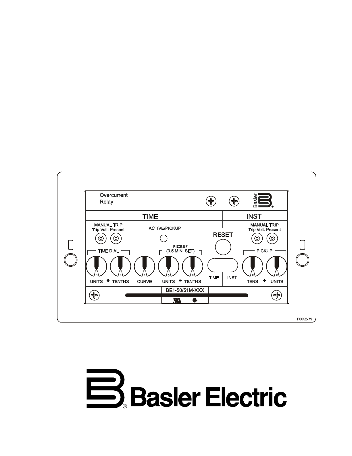
removed from the relay case. Figure 1-1 shows the front panel of the BE1-50/51M overcurrent relay, in a
C1, horizontal mount case. Figure 1-2 shows the front panel of the BE1-50/51M overcurrent relay, in a
C1, vertical mount case. Internally (circuit wise), all relay models are the same and use the same circuit
assemblies.
Advantages
BE1-50/51M overcurrent relays have many advantages over other overcurrent relays. The primary
advantages are:
• Time characteristics are defined by equations and graphs
• Field selectable time characteristics
• Very low burden extends the linear range of the CTs
• Self powered from the sensed current
• Continuous automatic calibration
9252000990 Rev R BE1-50/51M General Information 1-1
Page 12
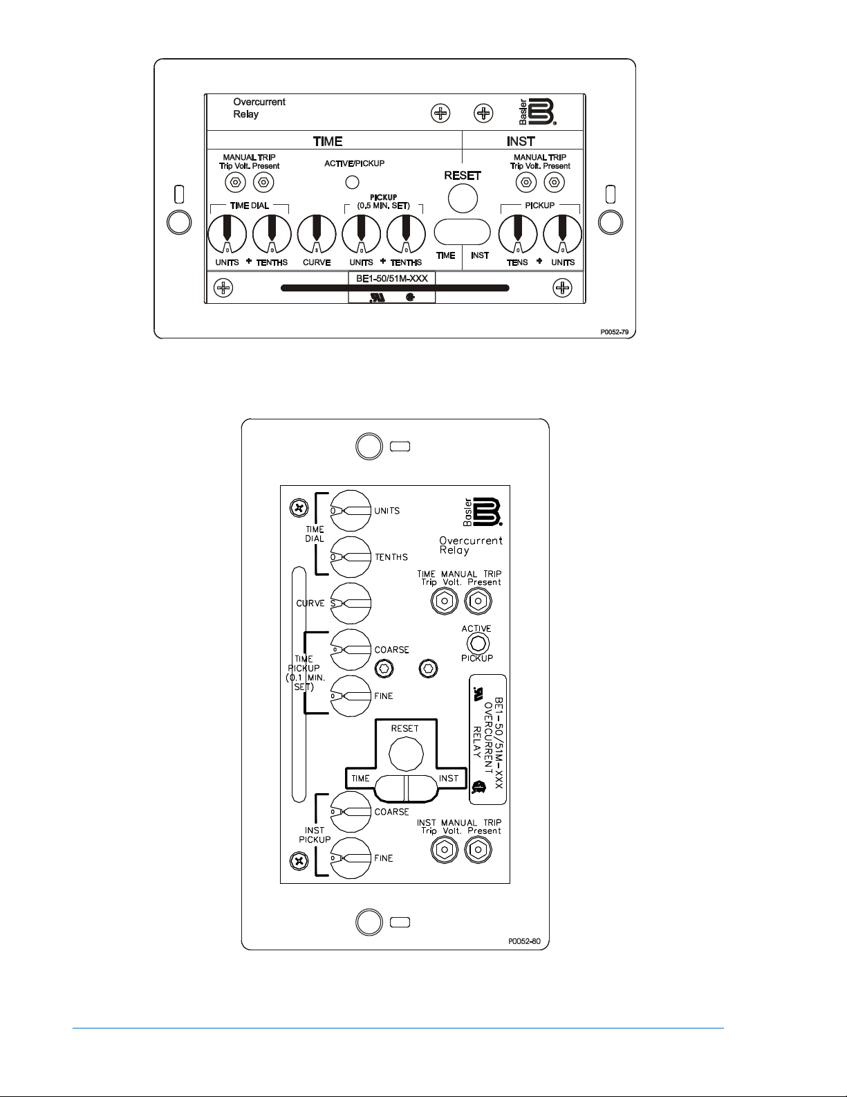
Figure 1-1. BE1-50/51M, C1 Horizontal Mount Case
Figure 1-2. BE1-50/51M, C1 Vertical Mount Case
1-2 BE1-50/51M General Information 9252000990 Rev R
Page 13

Model Numbers
Model number variations in the BE1-50/51M overcurrent relays are specified by a three digit extension to
the model number. Tables 1-1 and 1-2 provide model number, case style, switch SW3-3 selections, and
sensing current input ranges. Internal switches provide for selecting system operating frequencies of 50
or 60 Hz, instantaneous element delays, curve sets, and instantaneous or integrating reset
characteristics. The location and description of these switches is provided in Section 2. Integrating reset is
available in 100 series relays (e.g. - BE1-50/51M-100) when there is adequate input current to power the
relay. Integrating reset is available in 200 series relays (e.g. - BE1-50/51M-200) even when the input
current falls to zero. Two-hundred series relays also have additional characteristic curves available
through curve set selection.
Table 1-1. BE1-50/51M Overcurrent Relays, One Ampere CT Secondary, 50/60 Hz
Model Number Case Style SW3-3 Selects
BE1-50/51M-100
BE1-50/51M-200
BE1-50/51M-108
BE1-50/51M-208
Table 1-2. BE1-50/51M Overcurrent Relays, Five Ampere CT Secondary, 50/60 Hz
Model Number Case Style SW3-3 Selects
BE1-50/51M-104 C1 (Horizontal Mount) 0.2 Second Delay 0.5 - 15.9 1.0 - 99.0
BE1-50/51M-204 C1 (Horizontal Mount) Curve Set 0.5 - 15.9 1.0 - 99.0
BE1-50/51M-109 C1 (Vertical Mount) 0.2 Second Delay 0.5 - 15.9 1.0 - 99.0
BE1-50/51M-209 C1 (Vertical Mount) Curve Set 0.5 - 15.9 1.0 - 99.0
NOTE: 100 series relays (e.g. - BE1-50/51M-104) have the integrating reset function when there is
adequate input current to power the relay. 200 series relays (e.g. - BE1-50/51M-204) have the integrating
reset function even when the input current falls to zero.
C1 (Horizontal Mount)
C1 (Horizontal Mount)
C1 (Vertical Mount)
C1 (Vertical Mount)
0.2 Second Delay 0.1 - 3.18 0.2 - 19.8
Curve Set 0.1 - 3.18 0.2 - 19.8
0.2 Second Delay 0.1 - 3.18 0.2 - 19.8
Curve Set 0.1 - 3.18 0.2 - 19.8
Sensing Input Range (Amps)
TIME INST
Sensing Input Range (Amps)
TIME INST
9252000990 Rev R BE1-50/51M General Information 1-3
Page 14

Specifications
KBD
CM
AD
T
N
T
++=
-
BE1-50/51M overcurrent relays have the following features and capabilities.
Current Sensing Input
1 Ampere Unit
Continuous Current.................... 2.8 Aac
One Second Rating ................... 80 Aac
5 Ampere Unit
Continuous Current.................... 14 Aac
One Second Rating ................... 400 Aac
Time Overcurrent (51) Element
Setting the TIME PICKUP control at the minimum pickup setting (0.1 on the 1 ampere unit and 0.5 on the
5 ampere unit), places the relay in the most sensitive state and may be used as a safety setting.
1 Ampere Unit Pickup
Setting Range ............................ 0.1 to 3.18 Aac
Setting Increment ....................... 0.02 Aac
Accuracy .................................... ±2%, ±5 milliamperes at or above 0.1 ampere setting
5 Ampere Unit Pickup
Setting Range ............................ 0.5 to 15.9 Aac
Setting Increment ....................... 0.1 Aac
Accuracy .................................... ±2%, ±25 milliamperes at or above 0.5 ampere setting
Dropout
Dropout occurs at 95% of pickup value.
Timing Range
0.0 to 9.9 seconds in 0.1 second steps
Timing Accuracy
The timing accuracy is the sum of ±1 cycle, ±2%. This accuracy applies to the range of 1.3 to 40 times
tap and is for a given measured multiple of tap. The measurement of the multiple of tap has an accuracy
that is the sum of ±2%, ±25 milliamperes for 5 ampere units, and ±2%, ±5 milliamperes for 1 ampere
units.
Timing Accuracy Example (5 Ampere Unit)
PU setting .................................. 5 amperes
Current Applied .......................... 6.5 amperes
+ Multiple Tolerance .................. 6.655 amperes
– Multiple Tolerance .................. 6.345 amperes
Time Curve ................................ E
Time Dial .................................... 5.0
Minimum time dial
using 6.655 amperes ............... 46.5470 seconds
Maximum time dial
using 6.345 amperes ............... 61.3968 seconds
Curve time using 6.5 amperes ... 53.1800 seconds
Curve Characteristics
Nine inverse time functions and one fixed time function can be selected by the front-panel Curve switch.
Characteristic curves for the inverse and definite time functions are defined by the following equation.
Where: TT = time to trip in seconds
D = time dial setting
M = multiple of pickup setting
A, B, C, N, K = constants for the particular curve
1-4 BE1-50/51M General Information 9252000990 Rev R
Page 15

Time characteristic curve constants are listed in Tables 1-3 and 1-4. Constants have been selected to
conform to the characteristics of electromechanical relays over a range of pickup multiples from 1.3 to 40.
Values of the constants are provided for use in computer relay setting software. Timing accuracy is ±1
cycle, ±2 percent of time to trip.
Table 1-3. Time Characteristic Curve Constants with SW3-3 Open (Off)
(Series 100 or 200 Relays)
Curve Type ∗
BE1 Similar To A B C N K R
S ABB CO-2 A-1 0.2663 0.03393 1.000 1.2969 0.028 0.500
L ABB CO-5 A-2 5.6143 2.18592 1.000 1.000 0.028 15.750
D ABB CO-6 A-3 0.4797 0.21359 1.000 1.5625 0.028 0.875
M ABB CO-7 A-4 0.3022 0.12840 1.000 0.5000 0.028 1.750
I ABB CO-8 A-5 8.9341 0.17966 1.000 2.0938 0.028 9.000
V ABB CO-9 A-6 5.4678 0.10814 1.000 2.0469 0.028 5.500
E ABB CO-11 A-7 7.7624 0.02758 1.000 2.0938 0.028 7.750
B BS142-B ‡ A-8 1.4638 0.00000 1.000 1.0469 0.028 3.250
C BS142-C ‡ A-9 8.2506 0.00000 1.000 2.0469 0.028 8.000
F None § N/A 0.0000 1.00000 0.000 0.0000 0.000 1.000
Table 1-4. Time Characteristic Curve Constants with SW3-3 Closed (On)
Curve Type ∗
BE1 Similar To A B C N K R
S GE IAC 55 A-10 0.0286 0.0208 1.000 0.9844 0.028 0.0940
L GE IAC 66 A-11 2.3955 0.00002 1.000 0.3125 0.028 7.8001
D ABB CO-6 A-3 0.4797 0.21359 1.000 1.5625 0.028 0.8750
M ABB CO-7 A-4 0.3022 0.12840 1.000 0.5000 0.028 1.7500
I GE IAC 51 A-12 0.2747 0.1042 1.000 0.4375 0.028 0.8868
V GE IAC 53 A-13 4.4309 0.0991 1.000 1.9531 0.028 5.8231
E GE IAC 77 A-14 4.9883 0.0129 1.000 2.0469 0.028 4.7742
B BS142-B ‡ A-8 1.4636 0.00000 1.000 1.0469 0.028 3.2500
C BS142-C ‡ A-9 8.2506 0.00000 1.000 2.0469 0.028 8.0000
F None § N/A 0.0000 1.00000 0.000 0.0000 0.000 1.0000
Figure
Number †
(Series 200 Relays)
Figure
Number †
Constants
Constants
Notes for Tables 1-3 and 1-4
∗ BE1 Curve Types: S: Short Inverse V: Very Inverse
L: Long Inverse E: Extremely Inverse
D: Definite Time B: BS142 Very Inverse
M: Moderately Inverse C: BS142 Extremely Inverse
I: Inverse F: Fixed Time Delay
† Figure numbers refer to the characteristic curves located in Appendix A, Time Characteristic Curves.
‡ Curves B and C are defined in British Standard BS142 and IEC Standard IEC 255-4.
§ Fixed time delay, adjustable from 0.1 to 9.9 seconds.
9252000990 Rev R BE1-50/51M General Information 1-5
Page 16

Integrating Reset
1−
=
2
R
M
RD
T
Where:
M = Current in multiples of PICKUP setting during reset
1.0
10.0
100.0
0.000 0.200 0.400 0.600 0.800 1.000 1.200
Multiple of Pickup
xRD (Seconds)
P0046-11
Vertical axis xRD (Seconds) is applicable for all curves and is derived from
multiplying the constant R for the curve selected times D (the Time Dial setting).
Reset begins when the current drops below 95% of pickup and the relay has not timed out. Switch SW3-4
provides selection of either an instantaneous or integrating reset characteristic. Opening SW3-4 forces
the instantaneous reset timer to zero when timed dropout occurs. This fast reset characteristic prevents
the ratcheting effect that may occur with repeating system faults. Closing SW3-4 selects the integrating
reset characteristic. The integrating reset characteristic simulates the disk reset of electromechanical
relays. When the integrating reset characteristic is selected on 100 series relays, insure that sufficient
input power is available to power up the relay. This is not required on Series 200 relays. Series 200 relays
provide the integrating reset function even when input current falls to zero.
Integrating reset characteristics are defined by the following equation and shown in Figure 1-3. Equation
constants are provided in Tables 1-3 or 1-4.
Integrating Reset Equation:
TR = Time to reset in seconds
R = Constant for the particular curve
D = TIME DIAL setting
Figure 1-3. Integrating Reset Characteristic Curve
Instantaneous Overcurrent (50) Element
Setting the INST PICKUP to the minimum pickup (0.2 on the 1 ampere unit and 1.0 on the 5 ampere unit),
places the relay in the most sensitive state and may be used as a safety setting.
1 Ampere Unit Pickup
Setting Range ............................ 0.2 to 19.8 Aac
Setting Increment ....................... 0.2 Aac
Accuracy .................................... ±2%, ±5 milliamperes at or above 0.2 ampere setting
5 Ampere Unit Pickup
Setting Range ............................ 1 to 99 Aac
Setting Increment ....................... 1 Aac
Accuracy .................................... ±2%, ±25 milliamperes at or above 1.0 ampere setting
1-6 BE1-50/51M General Information 9252000990 Rev R
Page 17
Dropout
Dropout occurs at 95% of pickup value.
Curve Characteristics
BE1-50/51M instantaneous characteristic curves are similar to standard electromechanical instantaneous
units. However, the time to trip for ground applications is slightly longer than that for phase applications to
allow time to power up the relay. Longer trip time for ground applications is beneficial because it helps to
avoid nuisance trips.
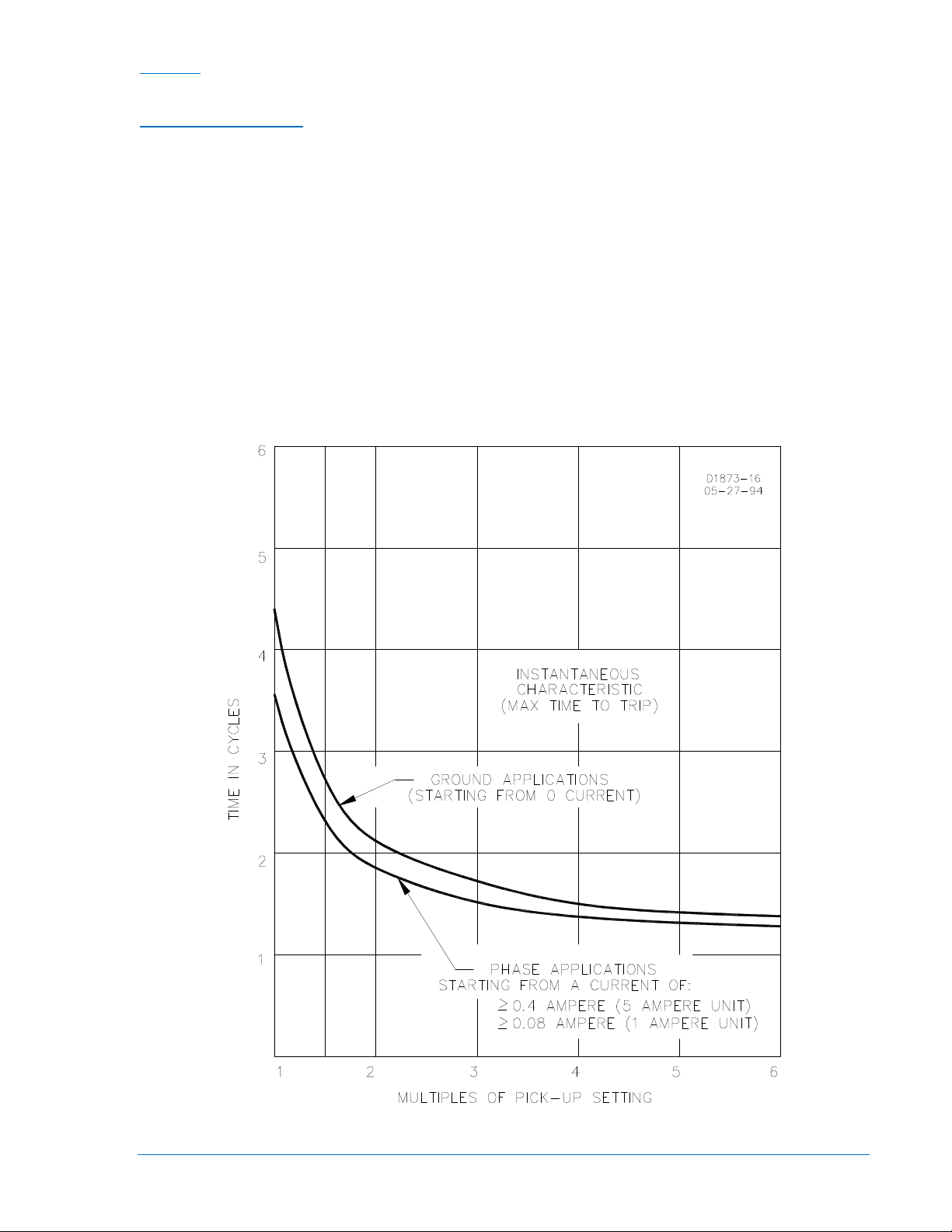
For phase applications, the maximum time to trip is 3.5 cycles at a pickup multiple of 1.0, and 1.5 cycles
at a pickup multiple of 3.0. The corresponding times for ground applications are 4.5 and 1.75 cycles.
Figure 1-4 shows the instantaneous characteristic curves for maximum time to trip.
On 100 series relays, additional delays of 0.1, 0.2, or 0.3 seconds may be added with internal switches
SW3-2 and SW3-3. These delays apply to both phase and ground applications. Closing switch SW3-2
provides an additional delay of 0.1 second. Closing switch SW3-3 provides an additional delay of 0.2
second. Closing both switches SW3-2 and SW3-3 provides an additional delay of 0.3 second. Section 2
illustrates the location of SW3.
On 200 series relays, an additional delay of 0.1 second may be added with internal switch SW3-2. This
delay applies to both phase and ground applications. Closing switch SW3-2 provides the additional delay
of 0.1 second.
Figure 1-4. Instantaneous Characteristic Curves
9252000990 Rev R BE1-50/51M General Information 1-7
Page 18
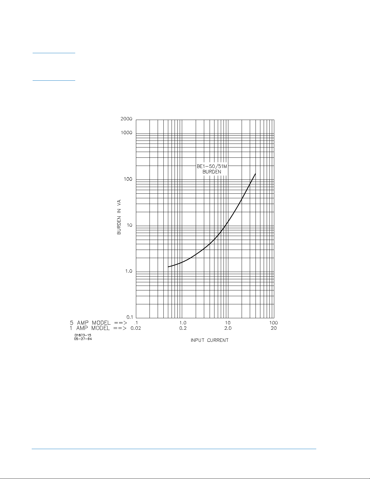
Burden
Burden is non-linear. Figure 1-5 illustrates the device burden.
1 Ampere Unit
0.1 amperes ............................... 120 Ω
1.0 ampere ................................. 5 Ω
5 Ampere Unit
0.5 amperes ............................... 4.8 Ω
5.0 amperes ............................... 0.2 Ω
Figure 1-5. Burden Characteristics
Frequency Response
A change of ±5 Hz from the nominal 50/60 Hz current causes <0.5% change in the current required for
pickup.
Transient Response
<10% overreach with system time constants up to 40 ms.
1-8 BE1-50/51M General Information 9252000990 Rev R
Page 19
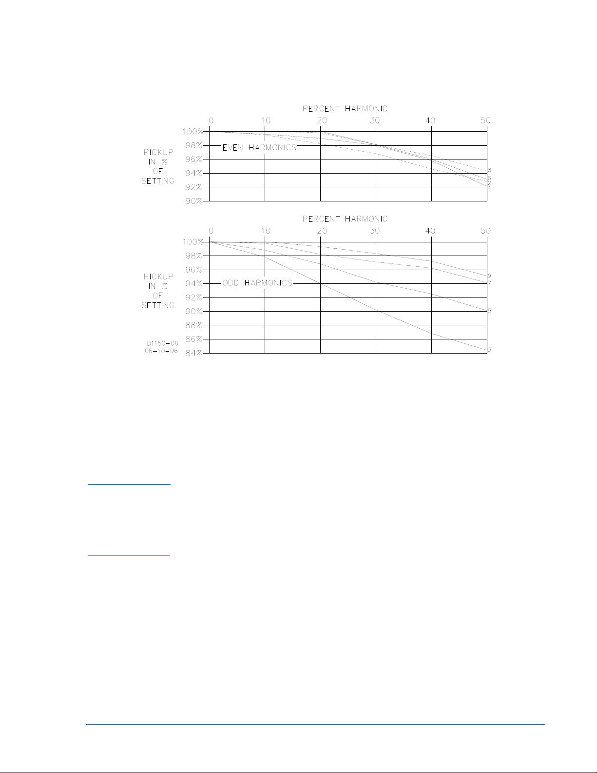
Harmonic Response
Figure 1-6 shows that a relay set for 1 ampere pickup would pick up at 0.96 amperes with a current
containing 40% seventh harmonic. This corresponds to a 10:1 rejection ratio. Other conditions may be
evaluated in the same manner.
Figure 1-6. Harmonic Rejection
Target Indicators
Gravity latched, manually reset targets indicate that current of 0.2 amperes or greater was present in the
trip circuit. Target coil resistance is less than 0.1 ohms and operate time is less than one millisecond. See
Output Contacts specifications for maximum current rating.
Output Contacts
Output contacts are surge protected and rated as follows.
Resistive Ratings
120/240 Vac ............................... Make 30 amperes for 0.2 seconds, carry 7 amperes for 2 minutes, 3
amperes continuously, and break 5 amperes.
125/250 Vdc ............................... Make 30 amperes for 0.2 seconds, carry 7 amperes for 2 minutes, 3
amperes continuously, and break 0.3 ampere.
Inductive Ratings
120/240 Vac, 125/250 Vdc ........ Make and carry 30 amperes for 0.2 seconds, carry 7 amperes for 2
minutes, 3 amperes continuously, and break 0.3 ampere. (L/R = 0.04).
AUX Output Contact
The AUX Output contact can be configured in the field using jumpers to select closing on either timed or
instantaneous trip. The AUX output contact is surge protected and has the same ratings as the output
contacts above.
9252000990 Rev R BE1-50/51M General Information 1-9
Page 20

Type Tests
Isolation ..................................... IEEE C37.90-2005
Transient Surge ......................... IEEE C37.90.1-2004
Radiated Interference ................ IEEE C37.90.2-2004
Electrostatic Discharge .............. IEEE C37.90.3-2006
Vibration ..................................... IEC 255-21-1
Shock and Bump ....................... IEC 255-21-2
Environment
Operating Temperature ............. –40°C to 70°C (–40°F to158°F)
Storage Temperature................. –50°C to 70°C (–58°F to 158°F).
Agency Recognition
UL Recognized/CSA Certified
UL Recognized per Standard 508, UL File No. E97033. CSA Certified per Standard CAN/CSA-C22.2 No.
14-M91, CSA File No. LR 23131.
Note: Output contacts are not UL Recognized/CSA Certified for voltages greater than 250 volts.
GOST-R Certification
GOST-R certified per the relevant standards of Gosstandart of Russia.
Physical
Weight ........................................ 5.2 lb (2.36 kg)
Patent
Patented in U.S., 1998, U.S. Patent No. 5751532.
1-10 BE1-50/51M General Information 9252000990 Rev R
Page 21

SECTION 2 • CONTROLS AND INDICATORS
TABLE OF CONTENTS
SECTION 2 • CONTROLS AND INDICATORS ........................................................................................ 2-1
Introduction ............................................................................................................................................ 2-1
Figures
Figure 2-1. Location of Controls and Indicators ........................................................................................ 2-1
Figure 2-2. Location of SW3 and Auxiliary Output Jumper Terminations
Tables
Table 2-1. BE1-50/51M Controls and Indicators (Refer to Figures 2-1 and 2-2) ...................................... 2-3
................................................. 2-2
9252000990 Rev R BE1-50/51M Controls and Indicators i
Page 22

ii BE1-50/51M Controls and Indicators 9252000990 Rev R
Page 23
SECTION 2 • CONTROLS AND INDICATORS
Introduction
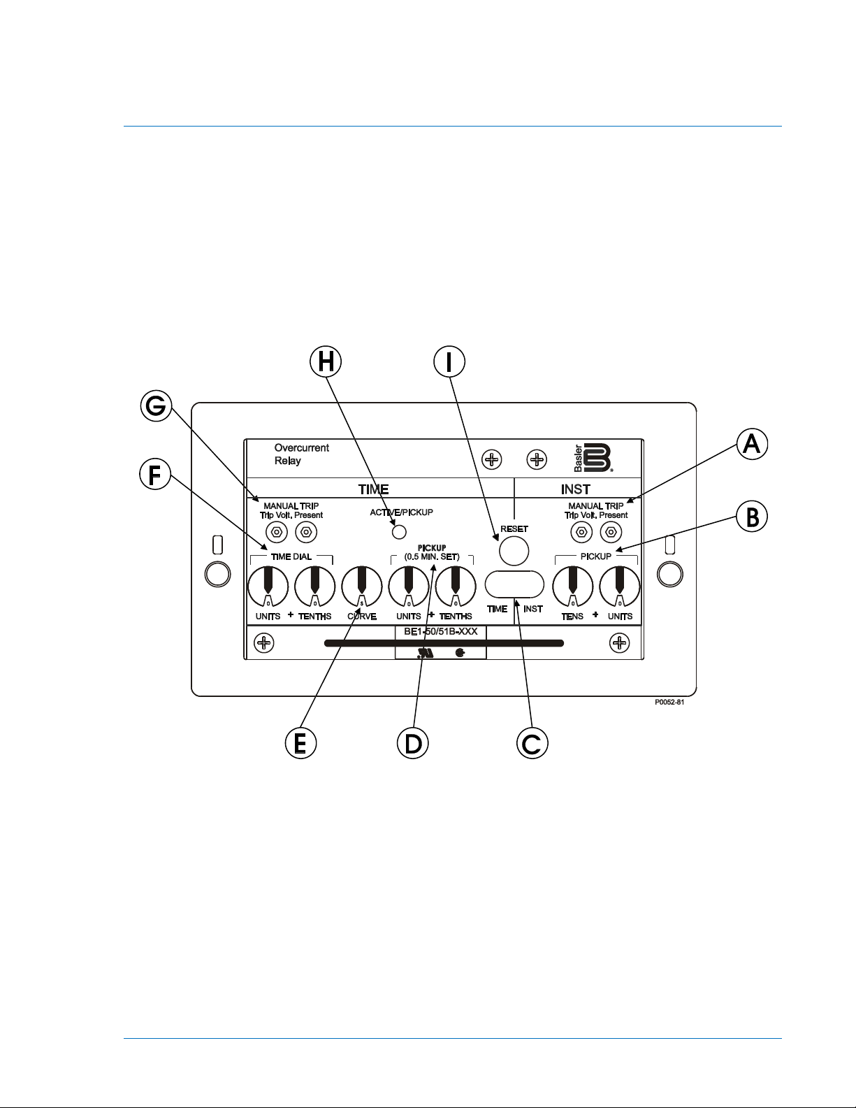
Figure 2-1 illustrates the front panel controls and indicators of the BE1-50/51M. Figure 2-2 illustrates the
location of switch SW3. Both illustrations have lettered call-outs that correspond to the control and
indicator descriptions provided in Table 2-1.
Figure 2-1. Location of Controls and Indicators
9252000990 Rev R BE1-50/51M Controls and Indicators 2-1
Page 24

P0053-49
J
K
Figure 2-2. Location of SW3 and Auxiliary Output Jumper Terminations
2-2 BE1-50/51M Controls and Indicators 9252000990 Rev R
Page 25

Table 2-1. BE1-50/51M Controls and Indicators (Refer to Figures 2-1 and 2-2)
Locator Control or Indicator Function
A INST MANUAL TRIP
Test Points
B INST PICKUP
Selectors
C Targets
D TIME PICKUP
Selectors
E CURVE Selector
F TIME DIAL Selectors
G TIME MANUAL TRIP
Test Points
When shorted, the test points (jacks) provide a secure means to
manually trip the controlled breaker. Jacks accept a standard 0.08
inch diameter phone tip plug.
Two switches (TENS and UNITS on five ampere models,
COARSE and FINE on one ampere models) to select pickup
current in amperes. Changing switch selectors while the relay is in
service may cause tripping.
Red target indicators latch when the trip circuit current is greater
than 0.2 amperes. One target each for TIME and INST.
Two switches (TENS and UNITS on five ampere models,
COARSE and FINE on one ampere models) to select pickup
current in amperes. Changing switch selectors while the relay is in
service may cause tripping.
Ten position selector switch to select one of nine inverse functions
or one fixed time function.
Two selector switches (UNITS and TENTHS) to select the desired
characteristic curve. A setting of 0.0 results in instantaneous
operation without any intentional delay. A setting of 9.9
corresponds to the typical time provided by an electromechanical
relay at its maximum dial setting.
When shorted, the test points provide a secure means to manually
trip the controlled breaker. Jacks accept a standard 0.08 inch
diameter phone tip plug.
H ACTIVE/PICKUP LED
I Target RESET Button
This bicolor LED indicates the level of current sensed by the relay.
A green LED indicates that the relay is active but not picked up.
The LED changes to red when the sensed current exceeds the
time overcurrent pickup setting and back to green when the
sensed current decreases below 95% of the time overcurrent
pickup setting.
Note: A minimum of 0.5 A (5A units) or 0.1 A (1A units) is required
to light the LED. The LED may not turn green (active) before
turning red (picked up) at the 0.5 A pickup setting on 5A units or
0.1 A pickup setting on 1A units.
Linkage extends through back of front cover to reset both gravity
latched target indicators.
9252000990 Rev R BE1-50/51M Controls and Indicators 2-3
Page 26

Locator Control or Indicator Function
J SW3-1
SW3-2
SW3-3
SW3-4
K
Auxiliary Output
Jumper Terminations
SW3-1 selects the system operating frequency. Opening SW3-1
(OFF) selects 60 hertz operation. Closing SW3-1 (ON) selects 50
hertz operation.
SW3-2 selects additional delay for the instantaneous element.
Closing SW3-2 (ON) provides an additional instantaneous delay of
0.1 seconds.
100 Series Relays
Closing SW3-3 (ON) provides an additional instantaneous delay of
0.2 seconds. Closing both SW3-2 (ON) and SW3-3 (ON) provides
an additional instantaneous delay of 0.3 seconds.
200 Series Relays
Opening SW3-3 (OFF) selects ABB type curves (refer to Table 1-
3.) Closing SW3-3 (ON) selects GE IAC type curves (refer to
Table 1-4).
SW3-4 provides selection of either instantaneous or integrating
reset characteristics. Closing SW3-4 (ON) selects integrating reset
characteristics. Opening SW3-4 (OFF) selects instantaneous reset
characteristics. See Section 1, General Information,
Specifications, for details on time reset.
Configures the auxiliary output contacts to close with either the
instantaneous (50) trip and/or the timed (51) trip.
Jumper E2 to E1A to close the auxiliary contact with the timed (51)
trip. This jumper is yellow and factory installed to close the
auxiliary output contacts with the timed trip.
Jumper E3 to E1B to close the auxiliary contact with the
instantaneous (50) trip. This jumper is blue and factory installed to
close the auxiliary output contacts with the instantaneous trip.
Users with BE1-50/51B unit revisions Q, R, and S in 100 series
relays and unit revisions H and previous in 200 series relays, refer
to Section 6 for the location of the auxiliary output jumper
terminations and the location of SW3. (Note: In all previous
revisions, the reference designator for SW3 was SW8.)
2-4 BE1-50/51M Controls and Indicators 9252000990 Rev R
Page 27

SECTION 3 • FUNCTIONAL DESCRIPTION
TABLE OF CONTENTS
SECTION 3 • FUNCTIONAL DESCRIPTION ........................................................................................... 3-1
General .................................................................................................................................................. 3-1
Functional Description ........................................................................................................................... 3-1
Sensing Input ..................................................................................................................................... 3-1
Power Supply ..................................................................................................................................... 3-1
Instantaneous Signal .......................................................................................................................... 3-1
Time Signal ........................................................................................................................................ 3-1
Microprocessor ................................................................................................................................... 3-1
Power-Off Sensing ............................................................................................................................. 3-1
Outputs ............................................................................................................................................... 3-1
Figures
Figure 3-1. Functional Block Diagram ....................................................................................................... 3-2
9252000990 Rev R BE1-50/51M Functional Description i
Page 28

ii BE1-50/51M Functional Description 9252000990 Rev R
Page 29

SECTION 3 • FUNCTIONAL DESCRIPTION
General
BE1-50/51M Overcurrent Relays are microprocessor based non-directional relays that measure ac
current to provide secure and reliable instantaneous and time overcurrent protection for power systems.
Functional Description
Sensing Input
Single phase ac current from system current transformers (CT) is brought into the overcurrent relay at
terminals 8 and 9. Refer to Figure 3-1 to follow the functional description. The input current is applied to
internal power and signal CTs.
Power Supply
Current from the power CT is rectified, filtered, and supplied to all relay internal circuitry for operating
power. A precision +5 Vdc supply also serves as a reference for automatic calibration.
Instantaneous Signal
Current from the signal CT is rectified and applied to the instantaneous scaling resistors controlled by the
INST PICKUP selector switches. The analog voltage of the instantaneous input signal developed across
the scaling resistors is filtered and applied to the multiplexor (MUX).
Time Signal
Current from the signal CT is also rectified and applied to the time scaling resistors controlled by the TIME
PICKUP selector switches. The analog voltage of the time input signal is also filtered and applied to the
multiplexor.
Microprocessor
Operating power from the power supply is applied to the microprocessor supervisor circuit. When the
microprocessor is active and executing code, the ACTIVE/PICKUP LED is green. When the input current
falls below an acceptable level, the supervisor circuit interrupts the microprocessor, halts further
operation, and turns OFF the ACTIVE/PICKUP LED. A microprocessor watchdog feature resets the
microprocessor program when the program flow is interrupted.
Information from the TIME DIAL selector switches, the TIME CURVE selector switch, INST DELAY
switches, and RESET CHAR switch is also applied to the microprocessor. The microprocessor uses
these inputs to set the operating parameters.
When the microprocessor is ready for analog information from the multiplexor, microprocessor control
signals cause the multiplexor to route the desired input through to the output. The output is converted
from an analog value to a digital value and applied to the microprocessor.
The microprocessor performs the program operations based on the inputs and the internal software
program. When the sensed current exceeds the TIME PICKUP setting, the ACTIVE/PICKUP LED turns
from green to red. The TIME (51) contact is closed in accordance with the TIME characteristic equation. If
the sensed current exceeds the INST PICKUP setting, the INST contact (50) is closed.
Power-Off Sensing
In 200 series relays, power-off sensing circuits measure the decaying voltage to determine the length of
time that power is removed (zero current). This provides information for the integrating reset function even
when power has been entirely removed.
Outputs
Instantaneous and Timed
System circuit breakers controlled by the output contacts can be manually tripped by applying a short
across the TIME or INST MANUAL TRIP front panel test points. Current flow in the trip circuit is indicated
by the operation of the target. The targets will not operate without adequate operating power for the relay.
9252000990 Rev R BE1-50/51M Functional Description 3-1
Page 30

CAUTION
POWER
CT SUPPLY
POWER
BRIDGE
CT
SIGNAL
TIME
SCALE
INST
SCALE
MUX
SW SW SW SW
TIME
PICKUP
INST
PICKUP
SWSW
SW
DOG
WATCH
SUPERVISOR
MICRO
51
50
TIME
DIAL
TIME
CURVE
50/60 Hz
INST DELAY
TP
TP
AUX
ISOLATION
TARGETS
MAGNETIC
ACTIVE/PICKUP
51
50
INPUT
GND
D1181-09
2
3
6
5
4
7
8
9
AND
A/D
CONVERTER
POWER-OFF
SENSING
SERIES 200 RELAYS ONLY
SW
RESET CHAR.
51
50
Trip circuit voltage is present at the front panel test points. When shorting the
test points, use insulated jumpers to avoid contact with these voltages.
Auxiliary
The auxiliary output contacts can be configured by the user to close when the timed and/or instantaneous
trip occurs. With both jumpers installed (this is the factory setting) either the timed or instantaneous trip
closes the auxiliary contacts. Effective with unit revision R, in units 9252000100 through 9252000109, the
printed circuit board was changed. Now, the PCB for 100 and 200 series relays are similar. Users with
units before revision R may see Section 6, Relay Differences, for installing auxiliary output contact
jumpers.
Figure 3-1. Functional Block Diagram
3-2 BE1-50/51M Functional Description 9252000990 Rev R
Page 31

SECTION 4 • INSTALLATION
TABLE OF CONTENTS
SECTION 4 • INSTALLATION .................................................................................................................. 4-1
General .................................................................................................................................................. 4-1
Mounting ................................................................................................................................................ 4-1
Connections ........................................................................................................................................... 4-3
Maintenance........................................................................................................................................... 4-7
Storage ................................................................................................................................................... 4-7
Figures
Figure 4-1. Rack Mounting Plate, Part Number 9252012001 ................................................................... 4-1
Figure 4-2. Outline Dimensions
Figure 4-3. Panel Drilling Diagram, C1 Case
Figure 4-4. AC Input Connections
Figure 4-5. DC Control Connections
Figure 4-6. BE1-50/51M Terminal Connections, Rear View
................................................................................................................. 4-2
............................................................................................ 4-3
............................................................................................................. 4-4
......................................................................................................... 4-5
..................................................................... 4-6
9252000990 Rev R BE1-50/51M Installation i
Page 32

ii BE1-50/51M Installation 9252000990 Rev R
Page 33

SECTION 4 • INSTALLATION
General
When not shipped as part of a control or switchgear panel, the relays are shipped in sturdy cartons to
prevent damage during transit. Immediately upon receipt of a relay, check the model and part number
against the requisition and packing list to see that they agree. Visually inspect the relay for damage that
may have occurred during shipment. If there is evidence of damage, immediately file a claim with the
carrier and notify the Regional Sales Office, or contact the Sales Representative at Basler Electric,
Highland, Illinois.
Proper operation of the relay may be confirmed by performing the operational test procedure of Section 5.
If the relay won't be installed immediately, store the relay in its original shipping carton in a moisture and
dust-free environment.
Mounting
A rack mounting plate (part number 9252012001) can be purchased to mount four BE1-50/51M (vertical
mount) relays side-by-side in a standard 19 inch wide rack. The rack mounting plate is four rack units
(seven inches) high and is shown in Figure 4-1. A cover (part number 9252012101) is also available that
covers one mounting location. Relay outline dimensions and panel drilling diagrams are shown in Figures
4-2 and 4-3.
Figure 4-1. Rack Mounting Plate, Part Number 9252012001
9252000990 Rev R BE1-50/51M Installation 4-1
Page 34

BS142 EXTREMELY INVERSEC
BS142 VERY INVERSE
B
F
FIXED TIME
E
EXTREMELY INVERSEDEFINITE TIME
D
MODERATELY INVERSE
M
I
INVERSE
V
VERY INVERSELONG INVERSEL
SHORT INVERSE
S
CURVE DEFINITIONS
OVERCURRENT
9 8 7 6
5
4
3
2
CT
AUX
GND
51
50
.850
5.950
7.000
4.000
6.875
5.625
6.250
.312
.315
.550
2.900
3.395
.500
(TYP)
(TYP)
.420
D1047-04
000S00
0
RESET
ACTIVE/PICKUP
PICKUP
(0.5 MIN. SET)
TIME DIAL
TENTHSUNITS
++
TENTHSUNITS CURVE
+
UNITSTENS
INSTTIME
PICKU
P
MANUAL TRIP
Trip Volt. Present
INST
Trip Volt. Present
TIM
E
MANUAL TRIP
R
Overcurrent
Relay
BE1-50/51B-XXX
Basler
Figure 4-2. Outline Dimensions
4-2 BE1-50/51M Installation 9252000990 Rev R
Page 35

Figure 4-3. Panel Drilling Diagram, C1 Case
When the relay is configured in a system with other devices, it is
Connections
Incorrect wiring may result in damage to the relay. Be sure to check model and part number before
connecting and energizing a particular relay.
NOTE
Be sure that the relay is hard-wired to earth ground with no smaller than 12
AWG copper wire attached to the ground terminal on the rear of the unit case.
recommended to use a separate lead to the ground bus from each unit.
9252000990 Rev R BE1-50/51M Installation 4-3
Page 36

Connections should be made with minimum wire size of 14 AWG except as noted for the ground wire.
Typical ac input and dc control connections are shown in Figures 4-4 and 4-5. The auxiliary output jumper
configuration schematic diagram is also shown in Figure 4-5. Relay internal connections are shown on the
back of the relay. Figure 4-6 shows a rear view of the relay and the connections.
Figure 4-4. AC Input Connections
4-4 BE1-50/51M Installation 9252000990 Rev R
Page 37

Figure 4-5. DC Control Connections
9252000990 Rev R BE1-50/51M Installation 4-5
Page 38

Figure 4-6. BE1-50/51M Terminal Connections, Rear View
4-6 BE1-50/51M Installation 9252000990 Rev R
Page 39

Maintenance
BE1-50/51M overcurrent relays require no preventive maintenance. However, periodic checks should be
performed according to scheduled practices. A recommended periodic test is provided in Section 5. If the
relay fails to function properly, contact the Technical Sales Support Department of Basler Electric.
Storage
This device contains long-life aluminum electrolytic capacitors. For devices that are not in service (spares
in storage), the life of these capacitors can be maximized by energizing the device for 30 minutes once
per year.
9252000990 Rev R BE1-50/51M Installation 4-7
Page 40

4-8 BE1-50/51M Installation 9252000990 Rev R
Page 41

SECTION 5 • TESTING
TABLE OF CONTENTS
SECTION 5 • TESTING ............................................................................................................................ 5-1
General .................................................................................................................................................. 5-1
Dielectric Test ........................................................................................................................................ 5-1
Operational Test Procedure ................................................................................................................... 5-1
Test Equipment Required................................................................................................................... 5-1
Test Procedure for Five Ampere Units ............................................................................................... 5-3
TIME Pickup Test ........................................................................................................................... 5-3
INST Pickup Test ............................................................................................................................ 5-3
Time Dial Test ................................................................................................................................. 5-3
Integrating Reset Test (Applicable Only to 200 Series Relays) ..................................................... 5-4
Target Test ..................................................................................................................................... 5-4
Manual Trip Test ............................................................................................................................. 5-4
Test Procedure for One Ampere Units ............................................................................................... 5-5
TIME Pickup Test ........................................................................................................................... 5-5
INST Pickup Test ............................................................................................................................ 5-5
Time Dial Test ................................................................................................................................. 5-6
Integrating Reset Test (Applicable Only to 200 Series Relays) ..................................................... 5-6
Target Test ..................................................................................................................................... 5-6
Manual Trip Test ............................................................................................................................. 5-7
Setting The Relay .................................................................................................................................. 5-7
Periodic Tests ........................................................................................................................................ 5-7
General ............................................................................................................................................... 5-7
Periodic Test ...................................................................................................................................... 5-7
Figures
Figure 5-1. Pickup and Timing Test Setup ................................................................................................ 5-2
Figure 5-2. Target Operational Test Setup
................................................................................................ 5-2
9252000990 Rev R BE1-50/51M Testing i
Page 42

ii BE1-50/51M Testing 9252000990 Rev R
Page 43

SECTION 5 • TESTING
General
Dielectric testing, operational testing, and periodic testing are described in the following paragraphs.
Dielectric Test
In accordance with IEC 255-5 and IEEE C37.90-2005, one-minute dielectric (high potential) tests may be
performed as follows:
All circuits to ground: 2,828 Vdc or 2,000 Vac.
Input to output circuits: 2,828 Vdc or 2,000 Vac.
Output contacts are surge protected.
Operational Test Procedure
The following procedures verify operation of BE1-50/51M relays. The test setups of Figures 5-1 and
5-2 are intended primarily as an illustration of the principles involved. Other test setups known to be
capable of testing with the stated and implied tolerances (including equipment specifically designed for
testing relays) may be used.
Test Equipment Required
• Current source with a range from 0 to 20 Aac (sensing input current)
• AC or DC voltage source (target operation)
• Timer or counter
CAUTION
When testing units with integrating reset characteristics selected, timing may
be affected by the integrating reset.
9252000990 Rev R BE1-50/51M Testing 5-1
Page 44

BE1-50/51M
9 8 7 6 5 4 2
TIME INST
3
CURRENT
SOURCE
INPUT
STOP
TIMER
START
AMPS
TEST SET
D2750-21
R
AC or DC
Voltage
Source
(V)
1 A Target Current
R = V/1
Rwatts = 1*V
Figure 5-1. Pickup and Timing Test Setup
5-2 BE1-50/51M Testing 9252000990 Rev R
Figure 5-2. Target Operational Test Setup
Page 45

NOTE
When testing TIME overcurrent functions, INST PICKUP settings of 00 will
affect the calibration of the TIME functions. TIME PICKUP settings of 00 also
affect INST functions.
Test Procedure for Five Ampere Units
TIME Pickup Test
Perform preliminary setup:
• Connect test setup as shown in Figure 5-1.
• Ensure that SW3 switches are set correctly: SW3-1 for operating frequency, SW3-2 to OFF (no
instantaneous delay), SW3-3 to OFF (no instantaneous delay (100 series relays) or ABB type
curves selected (200 series relays)), and SW3-4 to OFF (selects instantaneous reset).
• Set TIME DIAL to 0.0.
• Set CURVE to S
• Set TIME PICKUP to 0.5.
• Set INST PICKUP to 90.
Step 1. Slowly increase current to terminals 8 and 9. ACTIVE/PICKUP LED should turn RED at a
maximum input current of 0.550 ampere.
Step 2. Decrease input current until ACTIVE/PICKUP LED turns GREEN then OFF.
Step 3. Set TIME PICKUP to 2.2.
Step 4. Slowly increase current to terminals 8 and 9. ACTIVE/PICKUP LED should change from GREEN
to RED at an input current of 2.131 to 2.269 amperes.
Step 5. Decrease input current until ACTIVE/PICKUP LED turns GREEN then OFF.
INST Pickup Test
Perform preliminary setup:
• Connect test setup as shown in Figure 5-1.
• Ensure that SW3 switches are set correctly: SW3-1 for operating frequency, SW3-2 to OFF (no
instantaneous delay), SW3-3 to OFF (no instantaneous delay (100 series relays) or ABB type
curves selected (200 series relays)), and SW3-4 to OFF (selects instantaneous reset).
• Set TIME DIAL to 0.0.
• Set CURVE to S
• Set TIME PICKUP to 15.1.
• Set INST PICKUP to 01.
Step 1. Slowly increase current to terminals 8 and 9. INST contacts should close at an input current of
0.955 to 1.045 amperes.
Step 2. Decrease input current until INST output contacts open.
Step 3. Set INST PICKUP to 08.
Step 4. Slowly increase current to terminals 8 and 9. INST contacts should close at an input current of
7.815 to 8.185 amperes.
Step 5. Decrease input current until INST output contacts open.
Time Dial Test
Perform preliminary setup:
• Connect test setup as shown in Figure 5-1.
• Ensure that SW3 switches are set correctly: SW3-1 for operating frequency, SW3-2 to OFF (no
instantaneous delay), SW3-3 to OFF (no instantaneous delay (100 series relays) or ABB type
curves selected (200 series relays)), and SW3-4 to OFF (selects instantaneous reset).
• Set TIME DIAL to 4.5.
• Set CURVE to S
9252000990 Rev R BE1-50/51M Testing 5-3
Page 46

• Set TIME PICKUP to 1.0.
• Set INST PICKUP to 90.
Step 1. Prepare to apply 1.5 amperes input current to terminals 8 and 9 and record the elapsed time from
when current is applied until TIME output contacts close.
Step 2. Apply the current (step from 0 to 1.5 amperes) and record the elapsed time. Elapsed time should
be 1.754 to 2.084 seconds. (This tolerance is greater than ±2 % because it is the accumulation of
both pickup and timing tolerances.)
Step 3. Remove input current.
Integrating Reset Test (Applicable Only to 200 Series Relays)
Perform preliminary setup:
• Connect test setup as shown in Figure 5-1.
• Ensure that SW3 switches are set correctly: SW3-1 for operating frequency, SW3-2 to OFF (no
instantaneous delay), SW3-3 to OFF (no instantaneous delay (100 series relays) or ABB type
curves selected (200 series relays)), and SW3-4 to ON (selects integrating reset).
• Set TIME DIAL to 4.5.
• Set CURVE to I.
• Set TIME PICKUP to 1.0.
• Set INST PICKUP to 90.
Step 1. Set voltage source to provide a target current of 1.0 ampere.
Step 2. Read all of Step 3 before beginning Step 3.
Step 3. Apply 4.0 amperes input current to terminals 8 and 9. After the unit trips, remove the input current
for 20 ±0.25 seconds, then reapply the 4.0 amperes input current. Record the elapsed time from
the re-application of input current to the output retrip.
Result: Elapsed time should be 1.55 ±0.3 seconds.
Target Test
Perform preliminary setup:
• Connect test setup as shown in Figure 5-2.
• Ensure that SW3 switches are set correctly: SW3-1 for operating frequency, SW3-2 to OFF (no
instantaneous delay), SW3-3 to OFF (no instantaneous delay (100 series relays) or ABB type
curves selected (200 series relays)), and SW3-4 to OFF (selects instantaneous reset).
• Set TIME DIAL to 4.5.
• Set CURVE to S
• Set TIME PICKUP to 1.0.
• Set INST PICKUP to 01.
Step 1. Set voltage source to provide a target current of 1.0 ampere.
Step 2. Apply 5 amperes input current to terminals 8 and 9. Check that both TIME and INST targets
operate.
Step 3. Remove input current and reset targets.
Manual Trip Test
Perform preliminary setup:
• Connect test setup as shown in Figure 5-2.
• Ensure that SW3 switches are set correctly: SW3-1 for operating frequency, SW3-2 to OFF (no
instantaneous delay), SW3-3 to OFF (no instantaneous delay (100 series relays) or ABB type
curves selected (200 series relays)), and SW3-4 to OFF (selects instantaneous reset).
• Set TIME DIAL to 4.5.
• Set CURVE to S
• Set TIME PICKUP to 1.0.
• Set INST PICKUP to 01.
5-4 BE1-50/51M Testing 9252000990 Rev R
Page 47

WARNING!
Trip circuit voltage is present at the front panel test points. When shorting the
test points, use insulated jumpers to avoid contact with these voltages.
Step 1. Set voltage source to provide a target current of 1.0 ampere.
Step 2. Apply 0.9 ampere input current to terminals 8 and 9.
Step 3. Connect a jumper between TIME MANUAL TRIP test points. Check that TIME target operates.
Step 4. Connect a jumper between INST MANUAL TRIP test points. Check that INST target operates.
Step 5. Reset targets.
Test Procedure for One Ampere Units
TIME Pickup Test
Perform preliminary setup:
• Connect test setup as shown in Figure 5-1.
• Ensure that SW3 switches are set correctly: SW3-1 for operating frequency, SW3-2 to OFF (no
instantaneous delay), SW3-3 to OFF (no instantaneous delay (100 series relays) or ABB type
curves selected (200 series relays)), and SW3-4 to OFF (selects instantaneous reset).
• Set TIME DIAL to 0.0.
• Set CURVE to S
• Set TIME PICKUP to 0.1.
• Set INST PICKUP to 18.0.
Step 1. Slowly increase current to terminals 8 and 9. ACTIVE/PICKUP LED should turn RED at a
maximum input current of 0.11 ampere.
Step 2. Decrease input current until ACTIVE/PICKUP LED turns GREEN then OFF.
Step 3. Set TIME PICKUP to 0.44.
Step 4. Slowly increase current to terminals 8 and 9. ACTIVE/PICKUP LED should change from GREEN
to RED at an input current of 0.426 to 0.454 amperes.
Step 5. Decrease input current until ACTIVE/PICKUP LED turns Green then OFF.
INST Pickup Test
Perform preliminary setup:
• Connect test setup as shown in Figure 5-1.
• Ensure that SW3 switches are set correctly: SW3-1 for operating frequency, SW3-2 to OFF (no
instantaneous delay), SW3-3 to OFF (no instantaneous delay (100 series relays) or ABB type
curves selected (200 series relays)), and SW3-4 to OFF (selects instantaneous reset).
• Set TIME DIAL to 0.0.
• Set CURVE to S
• Set TIME PICKUP to 3.02.
• Set INST PICKUP to 0.2.
Step 1. Slowly increase current to terminals 8 and 9. INST contacts should close at an input current of
0.191 to 0.209 amperes.
Step 2. Decrease input current until INST output contacts open.
Step 3. Set INST PICKUP to 1.6.
Step 4. Slowly increase current to terminals 8 and 9. INST contacts should close at an input current of
1.563 to 1.637 amperes.
Step 5. Decrease input current until INST output contacts open.
9252000990 Rev R BE1-50/51M Testing 5-5
Page 48

Time Dial Test
Perform preliminary setup:
• Connect test setup as shown in Figure 5-1.
• Ensure that SW3 switches are set correctly: SW3-1 for operating frequency, SW3-2 to OFF (no
instantaneous delay), SW3-3 to OFF (no instantaneous delay (100 series relays) or ABB type
curves selected (200 series relays)), and SW3-4 to OFF (selects instantaneous reset).
• Set TIME DIAL to 4.5.
• Set CURVE to S
• Set TIME PICKUP to 0.2.
• Set INST PICKUP to 18.0.
Step 1. Prepare to apply 0.3 amperes input current to terminals 8 and 9 and record the elapsed time from
when current is applied until TIME output contacts close.
Step 2. Apply the current (step from 0 to 0.3 amperes) and record the elapsed time. Elapsed time should
be 1.754 to 2.084 seconds. (This tolerance is greater than ±2 % because it is the accumulation of
both pickup and timing tolerances.)
Step 3. Remove input current.
Integrating Reset Test (Applicable Only to 200 Series Relays)
Perform preliminary setup:
• Connect test setup as shown in Figure 5-1.
• Ensure that SW3 switches are set correctly: SW3-1 for operating frequency, SW3-2 to OFF (no
instantaneous delay), SW3-3 to OFF (no instantaneous delay (100 series relays) or ABB type
curves selected (200 series relays)), and SW3-4 to ON (selects integrating reset).
• Set TIME DIAL to 4.5.
• Set CURVE to I.
• Set TIME PICKUP to 0.2.
• Set INST PICKUP to 18.0.
Step 1. Set voltage source to provide a target current of 1.0 ampere.
Step 2. Read all of Step 3 before beginning Step 3.
Step 3. Apply 0.8 ampere input current to terminals 8 and 9. After the unit trips, remove the input current
for 20 ±0.25 seconds, then reapply the 0.8 ampere input current. Record the elapsed time from
the re-application of input current to the output retrip.
Result: Elapsed time should be 1.55 ±0.3 seconds.
Target Test
Perform preliminary setup:
• Connect test setup as shown in Figure 5-2.
• Ensure that SW3 switches are set correctly: SW3-1 for operating frequency, SW3-2 to OFF (no
instantaneous delay), SW3-3 to OFF (no instantaneous delay (100 series relays) or ABB type
curves selected (200 series relays)), and SW3-4 to OFF (selects instantaneous reset).
• Set TIME DIAL to 4.5.
• Set CURVE to S
• Set TIME PICKUP to 0.2.
• Set INST PICKUP to 0.2.
Step 1. Set voltage source to provide a target current of 1.0 ampere.
Step 2. Apply 1 ampere input current to terminals 8 and 9. Check that both TIME and INST targets
operate.
Step 3. Remove input current and reset targets.
5-6 BE1-50/51M Testing 9252000990 Rev R
Page 49

Manual Trip Test
Perform preliminary setup:
• Connect test setup as shown in Figure 5-2.
• Ensure that SW3 switches are set correctly: SW3-1 for operating frequency, SW3-2 to OFF (no
instantaneous delay), SW3-3 to OFF (no instantaneous delay (100 series relays) or ABB type
curves selected (200 series relays)), and SW3-4 to OFF (selects instantaneous reset).
• Set TIME DIAL to 4.5.
• Set CURVE to S
• Set TIME PICKUP to 0.2.
• Set INST PICKUP to 0.2.
WARNING!
Trip circuit voltage is present at the front panel test points. When shorting the
test points, use insulated jumpers to avoid contact with these voltages.
Step 1. Set voltage source to provide a target current of 1.0 ampere.
Step 2. Apply 0.15 ampere input current to terminals 8 and 9.
Step 3. Connect a jumper between TIME MANUAL TRIP test points. Check that TIME target operates.
Step 4. Connect a jumper between INST MANUAL TRIP test points. Check that INST target operates.
Step 5. Reset targets.
Setting The Relay
Select the desired relay settings before putting the relay into service. Changing pickup current settings
while the relay is in service may cause tripping.
Periodic Tests
General
All relays should be tested periodically to identify and correct any problems that are found.
Single phase relays such as the BE1-50/51M are normally used in groups of four (three phase and
ground) on the protected circuit. This relay scheme allows each unit to be withdrawn one at a time for
testing purposes without losing protection. Only three are required at any one time to sense all types of
faults on a grounded wye system. Refer to Figures 5-1 and 5-2 for recommended test setups.
Periodic Test
Periodic testing should consist of the following procedures.
Step 1. Verify that the instantaneous pickup is within ±2% of the value set on the dials. Pickup occurs
when the INST output contacts close.
Step 2. Verify that the time pickup is within ±2% of the value set on the dials. Pickup occurs when the
LED turns GREEN then RED.
Step 3. Verify that the time to trip for the curve and time dial settings at a multiple of six is the same as
the time given on the characteristic curve. Refer to Appendix A for the characteristics curves.
Step 4. Verify that the time to trip for the instantaneous element at a pickup multiple of 2 is not greater
than the time given on the instantaneous characteristic curve. Refer to Section 1 for the
instantaneous characteristic curve.
Step 5. Verify that the targets operate with one ac ampere of trip current in the trip circuits and that they
can be reset using the RESET BUTTON.
9252000990 Rev R BE1-50/51M Testing 5-7
Page 50

5-8 BE1-50/51M Testing 9252000990 Rev R
Page 51

SECTION 6 • RELAY DIFFERENCES
TABLE OF CONTENTS
SECTION 6 • RELAY DIFFERENCES ...................................................................................................... 6-1
General .................................................................................................................................................. 6-1
Differences ............................................................................................................................................. 6-1
Figures
Figure 6-1. Location of Controls and Indicators for unit revision Q and Previous, 100 Series Relays ..... 6-2
Figure 6-2. Location of Controls and Indicators for Unit Revisions R and S, 100 Series Relays and Unit
Revisions H and Previous, 200 Series Relays
.......................................................................................... 6-3
9252000990 Rev R BE1-50/51M Relay Differences i
Page 52

ii BE1-50/51M Relay Differences 9252000990 Rev R
Page 53

SECTION 6 • RELAY DIFFERENCES
General
This section provides the information necessary to support BE1-50/51M 100 series relays, revision S and
previous. In all unit revisions S and previous SW3 is the same as SW8.
Differences
BE1-50/51M 100 series relay boards revision Q and previous have the locations for controls and
indicators shown in Figure 6-1. BE1-50/51M 100 series relays, unit revisions R and S and 200 series
relays, unit revisions H and previous have the locations for controls and indicators shown in Figure 6-2.
Table 6-1 lists and briefly describes the operator controls of these relays. Reference the callout letters to
Figures 6-1 and 6-2.
Table 6-1. BE1-50/51M Controls and Indicators for 100 Series Relays Revision Q and Previous
Locator
J SW8-1
K
Control or
Auxiliary Output
Terminations
Indicator
SW8-2
SW8-3
SW8-4
Jumper
Function
SW8-1 selects the system operating frequency. SW8-1 open (OFF)
selects 60 hertz operation. SW8-1 closed (ON) selects 50 hertz
operation.
In 100 and 200 series relays,
instantaneous element. Switch SW8-2 closed (ON) provides an
additional instantaneous delay of 0.1 seconds.
In 100 series relays, switch SW8-3 closed (ON) provides an
additional instantaneous delay of 0.2 seconds. Closing both switches
SW8-2 and SW8-3 provides an additional instantaneous delay of 0.3
seconds.
In 200 series relays,
(refer to Table 1-3). SW8-3 closed (ON) selects GE IAC type curves
(refer to Table 1-4).
Provides selection of either instantaneous or integrating reset
characteristic. SW8-4 closed (ON) provides integrating reset. SW8-4
open (OFF) provides instantaneous reset.
Configures the auxiliary output contacts to close with either the
instantaneous (50) trip and/or the timed (51) trip.
Jumper E2 to E1A to close the auxiliary contact with the timed (51)
trip. This jumper is yellow and factory installed to close the auxiliary
output contacts with the timed trip.
Jumper E3 to E1B to close the auxiliary contact with the
instantaneous (50) trip. This jumper is blue and factory installed to
close the auxiliary output contacts with the instantaneous trip.
SW8-3 open (OFF) selects ABB type curves
SW8-2 selects additional delay for the
9252000990 Rev R BE1-50/51M Relay Differences 6-1
Page 54

Figure 6-1. Location of Controls and Indicators for unit revision Q and Previous, 100 Series Relays
6-2 BE1-50/51M Relay Differences 9252000990 Rev R
Page 55

J
D1181-08
K
1
ON
432
+
+
+
+
+
CR17
U7
Q2
W2
1 A
1
1
1
1 1
1
6
5
1
4
K3
C10
CR1CR4
C26
C27 C28
C29
C30
SW2
SW1
SW4SW3SW5SW6SW7
AR4 AR3
AR5
AR6
AR2
TPG
TP3
TP2
TP1
T2
P1
K1
K2
C12
C11
C14
R16
W3
AR1
C51
C3
E2E3
E1A
R17
E1B
C13
DS3DS2
T1
W4 W5
W6
W7
W8
CR19/C39
CR18/C38
4
1
4
1
ON
KA
R19
C9
C8
C5
C4
C52
C45
R33
R18
R5
R3
R6
R38
R14
Q1
R34
CR12
VR3
CR11
CR13
VR4
CR16
CR15
CR14
VR1
VR2
CR3
CR5
CR2
U9
CR10
U3
U8
R13
U15
SW8
U10
U12
U11
U13
U6
U4
U1
U2
CR9
U5
R15
U5
SW8
ON
AR3
2 3 4
ON
1
Y1
1
CR20/C40
W7
T1
E1B
E1A
E3 E2
K3
K4
Figure 6-2. Location of Controls and Indicators for Unit Revisions R and S, 100 Series Relays and Unit
Revisions H and Previous, 200 Series Relays
9252000990 Rev R BE1-50/51M Relay Differences 6-3
Page 56

6-4 BE1-50/51M Relay Differences 9252000990 Rev R
Page 57

APPENDIX A • TIME CHARACTERISTIC CURVES
TABLE OF CONTENTS
APPENDIX A • TIME CHARACTERISTIC CURVES ................................................................................ A-1
Time Characteristic Curves .................................................................................................................... A-1
Figures
Figure A-1. Time Characteristic Curve, S-Short Inverse (SW3-3 OFF, Similar to ABB CO-2) ................. A-1
Figure A-2. Time Characteristic Curve, L-Long Inverse (SW3-3 OFF, Similar to ABB CO-5)
Figure A-3. Time Characteristic Curve, D-Definite Time (Similar to ABB CO-6)
Figure A-4. Time Characteristic Curve, M-Moderately Inverse (Similar to ABB CO-7)
Figure A-5. Time Characteristic Curve, I-Inverse (SW3-3 OFF, Similar to ABB CO-8)
Figure A-6. Time Characteristic Curve, V-Very Inverse (SW3-3 OFF, Similar to ABB CO-9)
Figure A-7. Time Characteristic Curve, E-Extremely Inverse (SW3-3 OFF, Similar to ABB CO-11)
Figure A-8. Time Characteristic Curve, BS142-B (BS142 Very Inverse)
Figure A-9. Time Characteristic Curve, BS142-C (BS142 Extremely Inverse)
Figure A-10. Time Characteristic Curve, S2-Short Inverse (SW3-3 ON, Similar to GE IAC 55)
Figure A-11. Time Characteristic Curve, L2-Long Inverse (SW3-3 ON, Similar to GE IAC 66)
Figure A-12. Time Characteristic Curve, I2-Inverse (SW3-3 ON, Similar to GE IAC 51)
Figure A-13. Time Characteristic Curve, V2-Very Inverse (SW3-3 ON, Similar to GE IAC 53)
Figure A-14. Time Characteristic Curve, E2-Extremely Inverse (SW3-3 ON, Similar to GE IAC 77)
.................. A-2
...................................... A-3
............................. A-4
........................... A-5
................. A-6
........ A-7
.................................................. A-8
......................................... A-9
............. A-10
.............. A-11
........................ A-12
.............. A-13
..... A-14
9252000990 Rev R BE1-50/51M Time Characteristic Curves i
Page 58

ii BE1-50/51M Time Characteristic Curves 9252000990 Rev R
Page 59

APPENDIX A • TIME CHARACTERISTIC CURVES
Time Characteristic Curves
Figures A-1 through A-9 illustrate the time characteristic curves that are programmed into the nonvolatile
memory of series 100 relays. Figures A-1 through A-14 illustrate the characteristic curves that are
programmed into the nonvolatile memory of series 200 relays.
Figure A-1. Time Characteristic Curve, S-Short Inverse
(SW3-3 OFF, Similar to ABB CO-2)
9252000990 Rev R BE1-50/51M Time Characteristic Curves A-1
Page 60

Figure A-2. Time Characteristic Curve, L-Long Inverse
(SW3-3 OFF, Similar to ABB CO-5)
A-2 BE1-50/51M Time Characteristic Curves 9252000990 Rev R
Page 61

Figure A-3. Time Characteristic Curve, D-Definite Time
(Similar to ABB CO-6)
9252000990 Rev R BE1-50/51M Time Characteristic Curves A-3
Page 62

Figure A-4. Time Characteristic Curve, M-Moderately Inverse
(Similar to ABB CO-7)
A-4 BE1-50/51M Time Characteristic Curves 9252000990 Rev R
Page 63

Figure A-5. Time Characteristic Curve, I-Inverse
(SW3-3 OFF, Similar to ABB CO-8)
9252000990 Rev R BE1-50/51M Time Characteristic Curves A-5
Page 64

Figure A-6. Time Characteristic Curve, V-Very Inverse
(SW3-3 OFF, Similar to ABB CO-9)
A-6 BE1-50/51M Time Characteristic Curves 9252000990 Rev R
Page 65

Figure A-7. Time Characteristic Curve, E-Extremely Inverse
(SW3-3 OFF, Similar to ABB CO-11)
9252000990 Rev R BE1-50/51M Time Characteristic Curves A-7
Page 66

Figure A-8. Time Characteristic Curve, BS142-B
(BS142 Very Inverse)
A-8 BE1-50/51M Time Characteristic Curves 9252000990 Rev R
Page 67

Figure A-9. Time Characteristic Curve, BS142-C
(BS142 Extremely Inverse)
9252000990 Rev R BE1-50/51M Time Characteristic Curves A-9
Page 68

Figure A-10. Time Characteristic Curve, S2-Short Inverse
(SW3-3 ON, Similar to GE IAC 55)
A-10 BE1-50/51M Time Characteristic Curves 9252000990 Rev R
Page 69

Figure A-11. Time Characteristic Curve, L2-Long Inverse
(SW3-3 ON, Similar to GE IAC 66)
9252000990 Rev R BE1-50/51M Time Characteristic Curves A-11
Page 70

Figure A-12. Time Characteristic Curve, I2-Inverse
(SW3-3 ON, Similar to GE IAC 51)
A-12 BE1-50/51M Time Characteristic Curves 9252000990 Rev R
Page 71

Figure A-13. Time Characteristic Curve, V2-Very Inverse
(SW3-3 ON, Similar to GE IAC 53)
9252000990 Rev R BE1-50/51M Time Characteristic Curves A-13
Page 72

Figure A-14. Time Characteristic Curve, E2-Extremely Inverse
(SW3-3 ON, Similar to GE IAC 77)
A-14 BE1-50/51M Time Characteristic Curves 9252000990 Rev R
Page 73

Page 74

®
12570 State Route 143
Highland IL 62249-1074 USA
www.basler.com, info@basler.com
Phone +1 618.654.2341 Fax +1 618.654.2351
 Loading...