


PRESENTS YOUR
BALDOR GENERATORS
3815 OREGON STREET OSHKOSH WI 54902 PHONE: 920–236–4200 FAX: 920–236–4219
REVISED/EFFECTIVE MAY 1, 2003 |
C:\ISO9001\FORMS\SPSG–002–48msw |
FORM#: S–PSG–002–48 |
|
TOWABLES
OPERATOR’S MANUAL
Table of Contents
ACCESSORIES AND EQUIPMENT WITH THIS GENERATOR SET INCLUDES: |
|
ITEM |
PAGE |
SAFETY RECOMMENDATIONS: These recommendations must be read and followed |
1 |
to safely operate your generator set. |
|
VOLTAGE RATINGS: This informational page describes features and specifications for |
7 |
all Towable Units. |
|
ELECTRICAL CONNECTION INFORMATION: This information explains how to interface |
9 |
your generator with the AC loads and other standard and optional accessories. |
|
CONTROL PANEL: This includes a drawing of the control panel and a description of |
11 |
the components associated with it. |
|
PRE–START PROCEDURE: This described a pre–start check that should be performed |
14 |
prior to initial start–up. |
|
OPERATION GUIDE: Information on how to start, stop, and operate the generator set |
15 |
is included here. Included also is information in regards to the operation of the |
|
genset/ engine control device and the different fault shutdown circuits designed to |
|
protect the generator set from potential engine operational problems. |
|
TROUBLESHOOTING GUIDE: Included in this guide are basic instructions to help |
18 |
troubleshoot most problems with your generator set. For more troubleshooting |
|
help please contact the service department at Baldor Generators |
|
HIGHWAY TRAILER: This includes information in regards to safe operation, proper |
23 |
utilization, and recommended guidelines for using and operating the trailer. |
|
BALDOR GENERATORS WARRANTIES: this details the warranty provided by Baldor |
27 |
Generators for coverage for electrical generator end of the generator set. |
|
OTHER MANUALS AND ACCESSORIES THAT SHOULD ACCOMPANY YOUR TOWABLE
GENERATOR:
ENGINE OPERATOR’S MANUAL: This operator’s manual includes information in regards to the operation and maintenance of the engine utilized in this generator set.
AC GENERATOR, ACCESSORIES, AND LOAD CONNECTION DIAGRAMS / ENGINE
CONTROLS, ACCESSORIES, AND REMOTE CONNECTION DIAGRAMS: These diagrams contain information in regards to the internal wiring of the generator set, specifically the AC and Engine Control circuits. These diagrams will also include information for any optional AC or DC powered accessories that are included.
PARTS LIST: This is a listing of all parts used by Baldor Generators to build this specific generator set.

SAFETY WARNINGS
zPlace protective covers and guards over the rotating parts, if rotating parts such as the drive shaft, pulley, belt, etc. are left exposed, they are potentially hazardous.
zWhen cleaning, repairing or inspecting, make sure all moving parts have stopped.
zPrior to working on the generator set, disconnect the spark plug and battery to prevent accidental starting.
zUse only original equipment or authorized replacement parts. Use of correct parts will assure the operator of the safety integrity that was designed into the unit.
zUnauthorized modifications to the generator set may impair the function and/or safety of the unit.
zDo not operate the generator set without a muffler. Inspect periodically and replace if necessary.
zDo not touch the hot exhaust components or the high voltage spark plug and coil terminals. While Spark Plug Voltages are not normally lethal, an involuntary jerk of the hand caused by a hot surface or by
an electrical shock can result in injury.
zRepair of electrical generating equipment requires specialized skills. Repair personnel must have a thorough understanding of generator and small engine repair procedures.
zNever inhale exhaust gases. They contain carbon monoxide; a colorless, odorless and extremely dangerous gas that can cause unconsciousness or death. Symptoms of carbon monoxide poisoning can include: dizziness, nausea, headaches, sleepiness, vomiting or incoherency. If you or anyone else experiences any of these symptoms, get out into the fresh air immediately. Shut the unit down and
do not operate it until it has been inspected and, if necessary, repaired.
zNever Operate the generator set indoors or in a poorly ventilated area such as a tunnel or cave.
zCALIFORNIA PROPOSITION 65 WARNING: engine exhaust from this product contains chemicals known to the state of California to cause cancer, birth defects or other reproductive harm.
z Know how to stop the engine quickly and understand the operation of all controls.
Revised: 8/13/02 |
Page 1 of 4 |
FORM#: S–PSG–001–3 |
Effective: 2/27/98 |
|
C:\ISO9001\FORMS\SPSG0013.msw.bbk |
1
SAFETY WARNINGS
zNever permit anyone to operate the generator set without proper instructions.
zNever allow children to operate the generator set.
zChildren and pets must be kept away from the area of operation due to the possibility of burns from hot engine components or injury from any equipment the generator set is powering.
zAlways wear eye protection and Hearing protection when working near the generator set.
zOperate the generator set only with the guards, shields and other safety items in place and working properly.
zDo not put hands, feet, tools or other objects near rotating parts.
zUse reasonable care when moving or lifting the unit. The generator set may move around inside the wrap frame creating ”Pinch Points”.
zDo not run the generator set while it is being moved.
zDo not support the generator set from the top of the wrap frame.
zDo not operate the generator set while under the influence of alcohol, drugs or medication.
zWhen transporting or using a generator set with the wheel option, secure the unit to prevent it from moving around.
zDo not tamper with or change the engine speed as it has been preset at the factory for proper operation.
zKeep hands and face away from the carburetor when the air cleaner is being moved. A sudden backfire can cause serious burns.
zBe careful of hot parts. The muffler and other generator parts become very hot while the engine is running.
zDo not ”jump start” the generator set.
zSulfuric acid can cause severe injury and can give off gases, which are corrosive and potentially explosive. Avoid contact with skin, eyes, and clothing. In case of contact, flush area immediately with water.
zWhen transporting a generator set, secure it to prevent it from moving or shifting.
zKnow how to stop the engine quickly and understand the operation of all controls.
zDo not operate electrical equipment while standing in water, on wet ground or with wet hands or shoes.
zUse extreme caution when working on electrical components. Potentially dangerous voltage is present when the engine is running.
Revised: 8/13/02 |
Page 2 of 4 |
FORM#: S–PSG–001–3 |
Effective: 2/27/98 |
|
C:\ISO9001\FORMS\SPSG0013.msw.bbk |
2
SAFETY WARNINGS
zAlways treat the electrical circuits as if they were energized.
zDisconnect all leads plugged into the unit Prior to working on it.
zHave the electrical circuits serviced only by qualified technicians.
zInspect wiring frequently and replace frayed, broken or poor leads.
zDo not connect this unit to any building’s electrical system unless you utilize an approved transfer switch or the main service entrance switch has been disconnected and locked open.
zCircuit overload protection must be provided in accordance with national electrical codes and local regulations.
zCheck GFCI Receptacles monthly by using the ”Test” and ”Reset” buttons designed into them.
zDepending on your application it may be mandatory to ground or not ground this unit to earth ground. Comply with local electrical codes.
````FOR GASOLINE OR DIESEL POWERED GENERATOR SETS ````
zOperate the generator set on a level surface. If the generator set is tilted, fuel spillage may result.
zHandle fuel with care. It is highly flammable. Use only clean, properly marked and approved safety containers for refueling and storing fuel.
zStop the engine and allow it to cool before refueling.
zDo not overfill the fuel tank. Only fill the tank to within 1/2” of the top of the tank to allow space for fuel expansion.
zIf fuel is spilled, wipe it up carefully and wait until the fuel has dried before starting the engine.
zMake sure the fuel cap is properly closed after refueling.
zNever operate the generator set while smoking.
zNever operate the generator set near an open flame.
zNever store the generator set with fuel in the tank indoors or in an enclosed, poorly ventilated enclosure where fuel fumes may reach an open flame, electrical spark or pilot light as on a furnace, water heater, clothes dryer, etc.
zWhen transporting over long distances or rough roads, drain the fuel tank to prevent leakage and spillage.
Revised: 8/13/02 |
Page 3 of 4 |
FORM#: S–PSG–001–3 |
Effective: 2/27/98 |
|
C:\ISO9001\FORMS\SPSG0013.msw.bbk |
3
SAFETY WARNINGS
```` FOR GASOLINE OR DIESEL POWERED GENERATOR SETS ````
zCheck all fuel supply piping and their connections on a monthly basis for fuel leaks.
zUse only approved piping and componentry in your fuel supply system.
zA professional, experienced technician should only install the fuel supply system.
zDo not run the fuel line up against any sharp objects.
zComply with NFPA regulations and your local codes in regard to shut–off valves, regulators, etc. and any other recommendations or requirements they may have.
zKeep the generator set at least three feet away from buildings or other structures.
zKeep the generator set away from flammable and other hazardous materials (trash, rags, lubricants, explosives, paints, etc.)
zKeep the generator set free of grass, leaves and excessive grease and oils.
zAllow the generator set to cool before transporting it or storing it indoors.
zHave fire extinguisher accessible and nearby while operating the generator set.
zThis generator set must not be used on or near any forest covered brush covered or grass covered land unless the engine’s exhaust system is equipped with a spark arrester and it must be maintained
in effective working order by the operator.
zOperation inside an enclosed compartment or building is a potential fire hazard and should not be done unless approval is obtained from Baldor Generators. Engine/Generator overheating can cause severe damage due to restricted, obstructed or improper air–flow that is necessary for the proper cooling of the unit.
zHot exhaust gases being discharged by the engine must never be directed toward anything that could catch fire or explode.
Revised: 8/13/02 |
Page 4 of 4 |
FORM#: S–PSG–001–3 |
Effective: 2/27/98 |
|
C:\ISO9001\FORMS\SPSG0013.msw.bbk |
4
FORWARD
This manual contains the information you need to safely and efficiently operate your generator set. During the preparation of this manual every effort was made to ensure the accuracy of its contents.
Never operate this generator set without first carefully reading this manual and observing all the safety warnings it presents. While safety is built into every Baldor Pow’R Gard generator set, careless or improper operation could possibly result in mechanical failure, property damage, severe injury or death.
Note that this manual covers only very basic information in regards to the engine. A separate owner’s manual for the engine is supplied with this unit for your use. Please refer to this manual for information relative to engine operation, maintenance, recommendations and additional safety warnings.
As soon as you receive your generator set, inspect it closely for shipping damage. If you find some damage, notify the transportation company immediately and file a freight damage claim.
Think of this manual as a tool to help you get the most out of your generator set. We strongly suggest that you keep this manual with your generator set and refer to it when questions arise in regards to its operation.
Baldor Generators, formerly Pow’R Gard Generator Corporation has been in business since 1965. The generator sets we manufacture have earned the reputation of being of high quality and a dependable product. We take pride in this fact and continue to keep our quality standards high on our list of priorities. We are also constantly researching new technological ideas to determine if they could be used to make our generator sets even better.
Thank you for purchasing your Baldor Pow’R Gard Generator Set.
Effective: February 26, 1998 |
|
Revised 2/01/02 |
|
Form#: S–CSD–003–7 |
C:\ISO9001\FORMS\SCSD0037.MSW |
5
Effective: February 26, 1998 |
|
Revised 2/01/02 |
|
Form#: S–CSD–003–7 |
C:\ISO9001\FORMS\SCSD0037.MSW |
6
Features & Specifications
|
Model |
|
TS25 |
TS45 |
TS80 |
TS130 |
TS175 |
|
|
Standby output– |
1500C Rise |
|
|
|
|
|
|
|
(KVA/KW): |
|
|
|
|
|
|
|
|
3 PH @ 480 Volt |
|
|
|
|
|
|
|
|
25/20 |
48/38 |
81/65 |
|
134/107 |
175/140 |
||
|
3 PH @ 208/240 Volt |
25/20 |
46/37 |
72/58 |
|
131/105 |
169/135 |
|
|
1 PH @ 240 Volt |
18/18 |
27/27 |
45/45 |
|
70/70 |
80/80 |
|
|
Continuous Output– |
|
|
|
|
|
|
|
|
1250C Rise (KVA/KW): |
|
|
|
|
|
|
|
|
3 PH @ 480 Volt |
|
|
|
|
|
|
|
|
23/18 |
44/35 |
75/60 |
|
121/97 |
169/135 |
||
|
3 PH @ 208/240 Volt |
23/18 |
44/35 |
69/55 |
|
119/95 |
156/125 |
|
|
1 PH @ 240 Volt |
|
|
|
|
|
|
|
G |
18/18 |
25/25 |
43/43 |
|
66/66 |
75/75 |
||
E |
Voltage – 3 PH Adjustable |
208/220/240/ |
208/220/240/ |
208/220/240/ |
|
208/220/240/ |
208/220/240/ |
|
N |
|
|
416/440/460/480 |
416/440/460/480 |
416/440/460/480 |
|
416/440/460/480 |
416/440/460/480 |
|
|
|
|
|
|
|
|
|
E |
Voltage – 1 PH Adjustable |
120/127/139/ |
120/127/139/ |
120/127/139/ |
|
120/127/139/ |
120/127/139/ |
|
R |
|
|
240/254/277 |
240/254/277 |
240/254/277 |
|
240/254/277 |
240/254/277 |
A |
Amperage (Continuous): |
|
|
|
|
|
|
|
|
|
|
|
|
|
|||
T |
3 PH 480 Volt |
|
|
|
|
|
|
|
|
27.1 |
52.6 |
90.2 |
|
145.8 |
203.0 |
||
O |
3 PH 208 Volt |
|
|
|
|
|
|
|
|
62.5 |
121.4 |
190.8 |
|
329.6 |
433.7 |
||
R |
3 PH 240 Volt |
|
|
|
|
|
|
|
|
54.1 |
105.3 |
165.4 |
|
285.7 |
375.9 |
||
|
1 PH 240 Volt/120 Volt |
|
|
|
|
|
|
|
|
75.0/150.0 |
104.2/208.3 |
179.2/358.3 |
|
275/550 |
312.5/625.0 |
||
|
Receptacles: |
|
|
|
|
|
|
|
|
|
|
|
|
|
|
|
|
|
120 Volt, 15 Amp GFCI |
4 |
6 |
6 |
|
6 |
6 |
|
|
120/240 Volt, 50 Amp, |
2 |
3 |
3 |
|
3 |
3 |
|
|
CS6369 Twistlock |
|
|
|
|
|
|
|
|
Voltage Regulation 1/2% |
1/2% |
1/2% |
1/2% |
|
1/2% |
1/2% |
|
|
Power Factor – 3 Phase |
|
|
|
|
|
|
|
|
0.8 |
0.8 |
0.8 |
|
.08 |
.08 |
||
|
Frequency |
|
|
|
|
|
|
|
|
|
50 or 60 Hertz |
50 or 60 Hertz |
50 or 60 Hertz |
50 or 60 Hertz |
50 or 60 Hertz |
||
|
Total Harmonic Distortion |
|
|
|
|
|
|
|
|
<5% |
<5% |
<5% |
|
<5% |
<5% |
||
|
Insulation |
|
|
|
|
|
|
|
|
|
Class F |
Class F |
Class F |
Class F |
Class F |
||
|
|
|
|
|
|
|
|
|
|
Engine Make/Model |
Isuzu |
Isuzu |
John Deere |
John Deere |
John Deere |
||
|
|
|
4LE |
4BG1 |
TO4045T |
TO6068 |
RG6081T |
|
|
Design |
|
|
|
|
|
|
|
|
|
Water Cooled |
Water Cooled |
Water Cooled |
Water Cooled |
Water Cooled |
||
|
|
|
4 Cycle Diesel |
4 Cycle Diesel |
4 Cycle Diesel |
|
4 Cycle Diesel |
4 Cycle Diesel |
|
Starting System |
|
|
|
|
|
|
|
|
12 VDC |
12 VDC |
12 VDC |
12 VDC |
12 VDC |
|||
|
Displacement (cid) |
|
|
|
|
|
|
|
|
133.0 |
264.2 |
276.0 |
|
414.0 |
498.0 |
||
|
Cylinders |
|
|
|
|
|
|
|
|
|
4 |
4 |
4 |
|
6 |
6 |
|
|
HP @ Rated Speed |
|
|
|
|
|
|
|
|
34.5 |
64.0 |
100.0 |
|
166.0 |
211.0 |
||
|
RPM |
|
|
|
|
|
|
|
E |
|
1800 |
1800 |
1800 |
|
1800 |
1800 |
|
Safety Shutdowns: |
|
|
|
|
|
|
||
|
|
|
|
|
|
|||
N |
|
|
|
|
|
|
||
High Temperature |
Std. |
Std. |
Std. |
|
Std. |
Std. |
||
G |
|
|||||||
Low Oil |
|
Std. |
Std. |
Std. |
|
Std. |
Std. |
|
I |
|
|
||||||
Overspeed |
|
Std. |
Std. |
Std. |
|
Std. |
Std. |
|
N |
Overcrank |
|
Std. |
Std. |
Std. |
|
Std. |
Std. |
E |
Fuel Capacity |
|
|
|
|
|
|
|
|
50 |
80 |
80 |
|
160 |
160 |
||
|
Fuel Consumption (GPH): |
|
|
|
|
|
|
|
|
|
|
|
|
|
|
||
|
1/2 Load |
|
1.3 |
2.0 |
2.7 |
|
4.2 |
5.6 |
|
Full Load |
|
2.0 |
3.4 |
4.9 |
|
8.1 |
10.5 |
|
Approx. Run Time (Hrs.): |
|
|
|
|
|
|
|
|
|
|
|
|
|
|
||
|
1/2 Load |
|
38 |
40 |
30 |
|
38 |
29 |
|
Full Load |
|
25 |
24 |
16 |
|
20 |
15 |
|
Battery Recommendation Min. Cold |
|
|
|
|
|
|
|
|
750 |
900 |
900 |
|
(2) 750 |
(2) 750 |
||
|
Cranking Amps |
|
|
|
|
|
|
|
|
(Battery not included) |
|
|
|
|
|
|
|
|
|
|
|
|
|
|
|
|
|
Dimensions (L x W x H): |
|
|
|
|
|
|
|
|
With Trailer |
|
123” x 62” x 70” |
139” x 60” x 81” |
139” x 60” x 81” |
163” x 66” x 94” |
163” x 66” x 94” |
|
|
Without Trailer |
74” x 38” x 52” |
84” x 38” x 61” |
84” x 38” x 61” |
108” x 42” x 74” |
108” x 42” x 74” |
||
|
Weight (Lbs.): |
|
|
|
|
|
|
|
|
|
|
|
|
|
|
|
|
|
Without Fuel |
|
2265 |
3540 |
3848 |
|
5600 |
6200 |
|
Without Fuel & Trailer |
1790 |
2829 |
3053 |
|
4610 |
5205 |
|
|
|
|
|
|
|
|
|
|
7
8

SWITCHABLE
ELECTRICAL CONNECTION INFORMATION
WARNING: High voltage may be present at receptacles and load studs while engine is operating – DANGER of electrical shock is present. Use extreme care.
LOAD RECEPTACLES
1.Voltage is present in 120/240 volt switch position only.
2.Load wires may be brought into receptacle compartment through access door at control station.
HARD WIRE LOAD TERMINAL BLOCK
1.Voltage available at load block is outlined in chart below.
2.Cables must be brought into load block compartment through access hole in base of trailer.
3.Opening load block door will cause load disconnect to trip.
4.Do not start engine with load turned “on”. Allow engine to come up to speed and warm up (1).
5.If left unattended, lock all doors to prevent tampering or injury.
AVAILABLE VOLTAGE: |
|
SWITCH POSITION |
STUD |
277/480 |
1–2–3 = 480 VAC, 3 Phase |
|
1–N, 2–N, 3–N = 277 VAC, 1 Phase |
120/240 |
1–2–3 = 240 VAC, 3 Phase |
|
2–3 = 240 VAC, 1 Phase |
|
2–N, 3–N = 120 VAC, 1 Phase |
|
1–N = 180 – 200 VAC, Wild Leg |
120/208 |
1–2–3 = 208 VAC, 3 Phase |
|
2–3 = 208 VAC, 1 Phase |
|
1–N, 2–N, 3–N = 120 VAC, 1 Phase |
|
|
NOTE: To prevent damage to loads and generator, select voltage switch position prior to starting engine.
NOTE: Upon switching voltage selector switch, adjust voltage and adjust rheostat (located on engine control panel) for proper voltage.
Revised: October 3, 2002 |
D:\ISO9001\FORMS\MSW’98bbk |
Effective: April 23, 1999 |
|
Form#: S–PSG–001–15 |
|
9

CONNECTION INFORMATION
Your new Baldor Generator has all interconnecting wiring terminated at a junction box. All wiring will be clearly labeled as being load; remote start contacts and AC input terminals and are to be connected as described below.
Load – These connections are rated and sized according to the KW of the generator. Proper lead wire from these points to the automatic transfer switch (or load switching device) is mandatory. See enclosed transfer switch information for corresponding generator input terminals.
Remote Start Contacts – This two–wire connection, once connected to an appropriate switch, will start the generator and perform as described in the remote start/stop literature. These contacts are connected to the “Engine Start Contacts” of the automatic transfer switch.
A Two Pole normally open, closed to operate switch may also be used to start the generator.
AC Input – These connections are for units with float type battery chargers or engine block heater combinations. A Constant supply of 120 volts AC (or as specified) is needed at these terminals to power these devices.
NOTE: Power is not required when the unit is in operation. Internal battery charging and radiant heat during operation eliminate the need for these devices.
NOTE: It is recommended that units utilizing an automatic transfer switch with adjustable time delays have the initial adjustments made prior to start–up.
Factory recommendations are; allow a 2 second delay on start–up, 15–second delay on emergency to normal.
Revised: March 20,2001 |
D:\ISO9001\FORMS\MSW’98bbk |
Effective: April 23, 1999 |
|
Form#: S–PSG–001–19 |
|
10

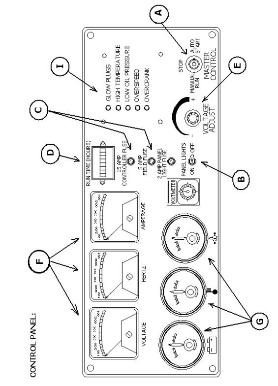
CONTROL PANEL OPERATION
AND FUNCTION
A.MASTER CONTROL SWITCH – This switch controls the starting and stopping of the engine via the engine control logic circuitry.
With this switch in the “Manual” mode, the engine will start and run immediately after a 10 – 20 second time delay.
CAUTION: Please note that once the engine has been told to start, the gen set should be treated as though it is operational, even though the start delay has not yet allowed the engine to crank.
With this switch in the “Automatic” mode, the engine can be started and stopped from a remote contact. (Standard switch, transfer switch, etc.) There is a time delay, to cool down, of 60–90 seconds when the unit is shut down from the remote contacts while the Master Control Switch is in the “Automatic Mode.
With this switch in the “Off” position, the engine will immediately stop. The position must also be utilized to clear fault shut–down conditions.
B.PANEL LIGHTS – By turning on the panel light switch, the panel lights will be energized and will illuminate the control panel. The fuse next to the switch is to protect this circuit from damage due to excessive current.
C.FIELD AND CONTROLLER FUSES – These fuses protect the internal workings of the generator set.
D.GAUGES – These gauges monitor some of the more critical operating parameters of the engine as well as the run time of the generator set.
The Voltmeter displays the charging rate that is currently being produced by the engine’s alternator to facilitate the charging of the battery. This gauge should normally be above 12.5V whenever the unit is running. If you ever notice the gauge is reading below 12V while the engine is running please contact the service department at Baldor Generators.
The Temperature Gauge monitors and displays the operating temperature of the engines coolant. The point at which a fault shut–down will occur is approximately 230° F.
The Oil Pressure Gauge displays and monitors the current operating pressure of the engine’s oil
system. The trip point at which a fault shutdown will occur is approximately 15 PSI or below.
Fuel level is checked by the owner or is usually a separately supplied fuel tank.
The Hour Meter accumulates and displays the total running time of the generator set.
11
E.VOLTAGE ADJUST – The rheostat allows the user to “fine tune” the generator set’s voltage output. It is normally used to adjust output voltage after switching the output of the generator set to a different voltage.
F.METERS – These meters monitor and display the current operating parameters of the generator set. The Voltmeter monitors and displays the current operating AC output of the generator set.
The Hertz Meter monitors and displays the current operating frequency of the generator set.
The ammeter monitors and displays the amount of current that is being delivered by the generator set. This meter works in conjunction with the Voltmeter Switch (Item G) in determining which output leg to monitor.
G.AMMETER SWITCH – The switch allows the user to switch between L1, L2 and L3 to monitor the current in each output leg of the generator.
H.PANEL LIGHT – By turning on the panel light switch, the panel lights (Not pictured on diagram) will be energized and will illuminate the control panel.
I – SYSTEM FAULT INDICATORS – These lights will come on when a fault condition or a warning condition develops.
The “Low Oil Pressure” light will come on when the engine’s oil pressure drops below 15 PSI. This condition will trigger a fault shut–down and the unit will stop.
The “Over–crank” light will come on when the engine has failed to start after four attempted crank cycles. Each crank cycle consists of a 12 second time period followed by a 12 second rest time period.
The “Over–speed” light will come on when the engine’s operating speed rises above it’s normal operating parameters. This condition will trigger a fault shut–down and the engine will stop.
High Temperature light will come on when the engine’s operating temperature exceeds the safety set–point.
12
13
OPERATION – PRE–START PROCEDURE
1.Fill system fuel tank with clean, fresh diesel fuel. CAUTION: Wipe up any and all fuel spillage.
2.Fill engine crankcase to full mark with clean, fresh lubricating oil per attached engine operating guide.
3.Radiator coolant should be checked at the beginning of each day and filled in compliance with the engine manufacturer’s guidelines.
4.Secure the generator for operation.
Skid mounted – the power generating system should be mounted to a smooth, hard surface suitable for supporting the system under all stress conditions.
Trailer mounted – block wheels to prevent accidental movement.
Adequate clearance must be provided for access doors to fully open.
NOTE: The generating system exhaust also exits radiator end. When positioning a generator system ensure position does not cause a concentration of toxic emissions.
14
 Loading...